EP3087625B1 - System zur lösbaren befestigung einer batterie oder eines batteriepacks an einem fahrzeug - Google Patents
System zur lösbaren befestigung einer batterie oder eines batteriepacks an einem fahrzeug Download PDFInfo
- Publication number
- EP3087625B1 EP3087625B1 EP14824002.1A EP14824002A EP3087625B1 EP 3087625 B1 EP3087625 B1 EP 3087625B1 EP 14824002 A EP14824002 A EP 14824002A EP 3087625 B1 EP3087625 B1 EP 3087625B1
- Authority
- EP
- European Patent Office
- Prior art keywords
- finger
- battery
- vehicle
- accessory
- equipment item
- Prior art date
- Legal status (The legal status is an assumption and is not a legal conclusion. Google has not performed a legal analysis and makes no representation as to the accuracy of the status listed.)
- Not-in-force
Links
- 239000012530 fluid Substances 0.000 claims description 17
- 238000013519 translation Methods 0.000 description 12
- 230000008901 benefit Effects 0.000 description 8
- 230000007246 mechanism Effects 0.000 description 6
- 239000000243 solution Substances 0.000 description 6
- 238000010616 electrical installation Methods 0.000 description 2
- BASFCYQUMIYNBI-UHFFFAOYSA-N platinum Chemical compound [Pt] BASFCYQUMIYNBI-UHFFFAOYSA-N 0.000 description 2
- 230000035939 shock Effects 0.000 description 2
- 230000001960 triggered effect Effects 0.000 description 2
- 230000009471 action Effects 0.000 description 1
- 230000008859 change Effects 0.000 description 1
- 239000002131 composite material Substances 0.000 description 1
- 238000011161 development Methods 0.000 description 1
- 239000012535 impurity Substances 0.000 description 1
- 238000002347 injection Methods 0.000 description 1
- 239000007924 injection Substances 0.000 description 1
- 238000012423 maintenance Methods 0.000 description 1
- 239000000463 material Substances 0.000 description 1
- 229910052751 metal Inorganic materials 0.000 description 1
- 239000002184 metal Substances 0.000 description 1
- 238000000034 method Methods 0.000 description 1
- 238000012986 modification Methods 0.000 description 1
- 230000004048 modification Effects 0.000 description 1
- 229910052697 platinum Inorganic materials 0.000 description 1
- 238000007789 sealing Methods 0.000 description 1
Images


Classifications
-
- B—PERFORMING OPERATIONS; TRANSPORTING
- B60—VEHICLES IN GENERAL
- B60K—ARRANGEMENT OR MOUNTING OF PROPULSION UNITS OR OF TRANSMISSIONS IN VEHICLES; ARRANGEMENT OR MOUNTING OF PLURAL DIVERSE PRIME-MOVERS IN VEHICLES; AUXILIARY DRIVES FOR VEHICLES; INSTRUMENTATION OR DASHBOARDS FOR VEHICLES; ARRANGEMENTS IN CONNECTION WITH COOLING, AIR INTAKE, GAS EXHAUST OR FUEL SUPPLY OF PROPULSION UNITS IN VEHICLES
- B60K1/00—Arrangement or mounting of electrical propulsion units
- B60K1/04—Arrangement or mounting of electrical propulsion units of the electric storage means for propulsion
-
- H—ELECTRICITY
- H01—ELECTRIC ELEMENTS
- H01M—PROCESSES OR MEANS, e.g. BATTERIES, FOR THE DIRECT CONVERSION OF CHEMICAL ENERGY INTO ELECTRICAL ENERGY
- H01M50/00—Constructional details or processes of manufacture of the non-active parts of electrochemical cells other than fuel cells, e.g. hybrid cells
- H01M50/20—Mountings; Secondary casings or frames; Racks, modules or packs; Suspension devices; Shock absorbers; Transport or carrying devices; Holders
- H01M50/262—Mountings; Secondary casings or frames; Racks, modules or packs; Suspension devices; Shock absorbers; Transport or carrying devices; Holders with fastening means, e.g. locks
- H01M50/264—Mountings; Secondary casings or frames; Racks, modules or packs; Suspension devices; Shock absorbers; Transport or carrying devices; Holders with fastening means, e.g. locks for cells or batteries, e.g. straps, tie rods or peripheral frames
-
- B—PERFORMING OPERATIONS; TRANSPORTING
- B60—VEHICLES IN GENERAL
- B60K—ARRANGEMENT OR MOUNTING OF PROPULSION UNITS OR OF TRANSMISSIONS IN VEHICLES; ARRANGEMENT OR MOUNTING OF PLURAL DIVERSE PRIME-MOVERS IN VEHICLES; AUXILIARY DRIVES FOR VEHICLES; INSTRUMENTATION OR DASHBOARDS FOR VEHICLES; ARRANGEMENTS IN CONNECTION WITH COOLING, AIR INTAKE, GAS EXHAUST OR FUEL SUPPLY OF PROPULSION UNITS IN VEHICLES
- B60K1/00—Arrangement or mounting of electrical propulsion units
- B60K1/04—Arrangement or mounting of electrical propulsion units of the electric storage means for propulsion
- B60K2001/0405—Arrangement or mounting of electrical propulsion units of the electric storage means for propulsion characterised by their position
- B60K2001/0438—Arrangement under the floor
-
- B—PERFORMING OPERATIONS; TRANSPORTING
- B60—VEHICLES IN GENERAL
- B60K—ARRANGEMENT OR MOUNTING OF PROPULSION UNITS OR OF TRANSMISSIONS IN VEHICLES; ARRANGEMENT OR MOUNTING OF PLURAL DIVERSE PRIME-MOVERS IN VEHICLES; AUXILIARY DRIVES FOR VEHICLES; INSTRUMENTATION OR DASHBOARDS FOR VEHICLES; ARRANGEMENTS IN CONNECTION WITH COOLING, AIR INTAKE, GAS EXHAUST OR FUEL SUPPLY OF PROPULSION UNITS IN VEHICLES
- B60K1/00—Arrangement or mounting of electrical propulsion units
- B60K1/04—Arrangement or mounting of electrical propulsion units of the electric storage means for propulsion
- B60K2001/0455—Removal or replacement of the energy storages
- B60K2001/0472—Removal or replacement of the energy storages from below
-
- H—ELECTRICITY
- H01—ELECTRIC ELEMENTS
- H01M—PROCESSES OR MEANS, e.g. BATTERIES, FOR THE DIRECT CONVERSION OF CHEMICAL ENERGY INTO ELECTRICAL ENERGY
- H01M2220/00—Batteries for particular applications
- H01M2220/20—Batteries in motive systems, e.g. vehicle, ship, plane
-
- Y—GENERAL TAGGING OF NEW TECHNOLOGICAL DEVELOPMENTS; GENERAL TAGGING OF CROSS-SECTIONAL TECHNOLOGIES SPANNING OVER SEVERAL SECTIONS OF THE IPC; TECHNICAL SUBJECTS COVERED BY FORMER USPC CROSS-REFERENCE ART COLLECTIONS [XRACs] AND DIGESTS
- Y02—TECHNOLOGIES OR APPLICATIONS FOR MITIGATION OR ADAPTATION AGAINST CLIMATE CHANGE
- Y02E—REDUCTION OF GREENHOUSE GAS [GHG] EMISSIONS, RELATED TO ENERGY GENERATION, TRANSMISSION OR DISTRIBUTION
- Y02E60/00—Enabling technologies; Technologies with a potential or indirect contribution to GHG emissions mitigation
- Y02E60/10—Energy storage using batteries
Definitions
- the present description generally relates to fastening systems for accessories to a motor vehicle and, more particularly, the attachment of a battery in a motor vehicle.
- connection of the batteries is now generally made using a connector of which a male or female part is carried by a battery box and whose opposite part, female or male, is carried by the vehicle.
- the battery cases are larger and must be firmly attached while remaining removable. They are therefore usually screwed.
- the batteries need to be changed, whether during maintenance operations to be replaced, or simply to be recharged.
- Using a screwing system requires preserving access for a tool when setting up the battery. These screwing areas are often difficult to access.
- the document FR-A-2,197,353 describes a device for mounting the storage battery of an electric vehicle, comprising a self-supporting removable pallet made in the form of a container belonging to the carrier assembly of the assembly constituting the floor of the electric vehicle of which it can be removed from below.
- the document FR-A-2 954 594 discloses a device for removably attaching a battery of a motor vehicle comprising an upper part comprising a fixing means on a motor vehicle and a lower part comprising a means of connection with the battery, and a lock connected to an axis of rotation and connected to a piston on which an elastic means acts to lock and unlock the two upper and lower parts between them by a translation and a rotation of the lock.
- WO-2011/124700 discloses a device for removably attaching a battery.
- the document FR-A-2 940 638 describes a method of fixing a battery under the body of a motor vehicle.
- An object of an embodiment of the present description is to provide a mechanism for removably attaching a battery that overcomes all or part of the disadvantages of the usual mechanisms.
- Another object of an embodiment is to provide a solution requiring no access space at the battery for a tool during assembly or disassembly of the battery.
- Another object of an embodiment is to propose a solution facilitating the assembly and disassembly of a battery.
- Another object of an embodiment is to propose a solution compatible with the addition of an anti-theft system to the battery.
- each actuating device comprises an elastic return element to a locked position of the fixing device, which can be pneumatically constrained to an unlocked position.
- the accessory is a battery or a set of batteries.
- the accessory is a wheel.
- the same fluid access point is shared by several fixing devices.
- said finger is of circular cross section.
- the locking element is on the female side.
- said locking element comprises a rod moved in said housing, in translation perpendicular to the longitudinal direction of said finger.
- the locking element comprises a stirrup whose ends of legs are intended to be engaged in the groove in the locked position.
- the locking element is on the male part side and comprises at least three coplanar balls held in the groove of the finger, movable between an unlocked position where the balls are contained in the groove and a locked position where they exit partially throat.
- the first equipment is the vehicle, the second equipment being the accessory.
- Equipment is also provided from an accessory and a vehicle having male parts of removable fasteners of a system as above, with the fluid distribution circuit being contained in said equipment. Provision is also made of equipment among an accessory and a vehicle comprising female parts of removable fasteners of a system as above, with the fluid distribution circuit being contained in said equipment.
- the figure 1 is a schematic representation in perspective of a motor vehicle, equipped with a battery or a set of batteries 2, for example placed under the floor of the vehicle and accessible from below the vehicle, from the outside.
- the batteries thus equipping the vehicles are bolted to it and a connector 22 connects the battery to the electrical installation of the vehicle (not shown).
- the figure 2 is a schematic sectional view of an embodiment of a removable attachment system of a battery 2 to a support 1, for example the chassis of a vehicle.
- a battery pack that is to say to a housing containing one or more batteries.
- the fixing system comprises several devices 3 or fixing mechanisms, each consisting of a male part 4, in the example shown on the battery side, and a female part 5, in the example shown on the battery support side 1 (here the vehicle) . It is possible to envisage a single battery device, but for reasons of weight and resistance, it will be preferable to use several devices.
- the male part 4 consists of a finger 40 protruding from the surface of the battery 2 (in practice of its housing).
- the battery is intended to be, at least partially, in contact with a wall of the support 1.
- the finger 40 has an annular groove 42 intended to participate in locking.
- the male part 4 is fixed permanently to the battery case, for example by being glued, welded or screwed to it by means of a platinum of 44. It may also be provided that, in some embodiments, the finger 40 is directly molded or machined with the housing, if the mechanical strength thereof permits.
- each female part 5 comprises a housing 52 for receiving a finger 40 of a male part and, in this example, a locking member 62, intended to cooperate with the groove 42 of the finger 40 to lock in translation the finger in the dwelling 52.
- the locking element is formed of a rod 62 moved in translation perpendicular to the longitudinal direction of the finger 40 (moved horizontally in the orientation of the figure).
- the rest position of the rod 62 is a locked position in which it leaves in the housing 52 to engage in the groove 42 (function symbolized by a spring 65 between the base of the rod 62 and the bottom of the a duct 63).
- a mechanism for actuating the rod 62 makes it possible to cause a retraction in the duct 63, out of the housing 52, to release the finger 40.
- all the actuating mechanisms of the rods 62 are centrally controllable from a central unit 7 ( figure 1 ) of control, connected (links 72) to each of the fixing devices 3 of the battery.
- a central unit 7 figure 1
- links 72 links 72
- a battery 2 fixed with four devices 3. This number may vary depending in particular on the weight and volume of the battery.
- the connector 22 equipping the battery is intended to be electrically connected to a corresponding portion 24 of the vehicle chassis, connected to equipment exploiting the battery power.
- the male parts are battery side and the female parts are support side.
- this has the advantage, especially for a battery placed under the vehicle, that the housing 52 are not likely to fill with impurities.
- the equipment handled being the battery, it facilitated its implementation.
- this facilitates a centralized control on the vehicle side.
- it may also provide a lateral fixation on a support, the fixing fingers then being horizontal.
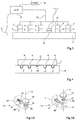
- the figure 3 is a schematic representation in the form of blocks of a removable fixing system of a battery illustrating its operation.
- the different locking elements ( figure 2 ) associated with the female parts 5 are preferably controlled simultaneously by a common actuator 75 (ACT) itself triggered by a control circuit 76 (CTRL).
- ACT common actuator 75
- CTRL control circuit 76
- the actuation of the locking elements is pneumatic. Pneumatic actuation is preferred for its simplicity and the absence of fluid other than air.
- a pneumatic embodiment has the advantage that air compressors are generally present in automobile garages or near the charging stations and that it is then enough for the user to connect a compressed air supply to an outlet 77 provided then at the vehicle (for example at its chassis) to provide the energy required to actuate the fastening system.
- Pneumatic lines 78 then distribute the compressed air from the actuator 75 to the fasteners.
- a pneumatic actuation has the advantage of being particularly adapted to the forces required to unlock the device.
- an electrical system would require to embark, near each fixing device, an electric motor, a gear, etc. In addition to clutter and complexity, these elements may clash.
- the fluid supply pipes can be compact.
- a such a solution is compatible with a centralized control, whether it is for example by equipping the vehicle with a compressor or by providing, for each device or for several devices at a time, a pneumatic plug 77 or access point, accessible from the outside the vehicle, for example to connect the air outlet of a compressor when it is desired to disassemble the battery.
- the need to ship a compressor can indeed be seen as inconvenient.
- the solution described is particularly suitable.
- a simple hand pump or foot connected to this socket can suffice.
- a common control element 76 makes it possible, according to a preferred embodiment, to link the release of the battery 2 to an anti-theft mechanism.
- the actuator 75 can be triggered only if the key (electronic or mechanical) of the vehicle is present to trigger the control circuit 76.
- the actuation itself participates in the antitheft function insofar as the unlocking requires a fluid injection element or air.
- the figure 4 illustrates, very schematically, an embodiment of a recharging station 8 of a battery 2.
- the charging station 8 is also equipped with female parts 5 'of fixing devices, 2.
- the charging station 8 comprises somehow a battery holder of the same type as that fitted to the vehicle.
- the battery is then reported at its station 8 and its connector 22 is connected to an element power supply 84 of the charging station so that the battery is recharged.
- the devices on the vehicle side and charging station side may be different from each other, whether in their structures or in their actuation systems, provided that they are compatible with the fingers equipping, for example, the battery .
- the devices on different vehicles may be different from each other provided they are compatible with the part carried by the batteries.
- fastening devices 3 are, when the battery is locked on the support, inaccessible. Not only does this protect them mechanically against shocks, but it also contributes to theft protection.
- the mechanical part ensuring the unlocking is not accessible from the outside, only the pressurized fluid makes it possible to operate the unlocking.
- one or more "leakage” valves are added to the fluid circuits, that is to say valves which, in their state of rest, open the fluid circuit so that it is impossible to raise the pressure to unlock the fasteners. These valves are closed during an authorized pressurization by means of an electric or mechanical key. Alternatively, relays / valves shut off at rest the line between the plug 77 and the one or more fasteners.
- an electrical connector 22 separate from the fastening devices is preferred, it may alternatively be provided that the electrical connection passes through one or more fasteners.
- the Figures 5A and 5B illustrate a first embodiment of a fixing device 3a.
- the Figure 5A represents the device in the locked (closed) position.
- the Figure 5B represents the device in unlocked (open) mode. It should be noted that the orientation of the device to Figures 3A and 3B is reversed compared to that of the figure 2 that is to say that the male part 4 is in the upper part while the female part 5 is in the lower part. It does not change the operation.
- a rod 62 is capable of being moved in translation in a conduit 63 fitted to the female part so as to engage in the groove 42 of the finger in a direction intersecting the axis A of the finger 40.
- the rod 62 acts in the manner of the rod of a jack and the supply of air in a pneumatic embodiment is located in the front part of the rod 62 so as to constrain it against for example the action of a spring 65 provided between the bottom of the duct 63 and a head of the rod 62.
- Other embodiments are possible for actuation.
- FIGS 6A and 6B are perspective views, respectively in the locked position and in the unlocked position, of another embodiment of a fixing device 3b.
- the difference is that the rod 62 of the locking member is moved in a tangential direction to the finger 4. This improves the strength and in particular reduces the risk of shifting the electrical connector of the battery following vibrations.
- the rest is similar to the embodiment of the Figures 5A and 5B .
- FIGS. 7A and 7B show, schematically, by perspective views, respectively in the closed position and in the open position, yet another embodiment of a fixing device 3c comprising a stirrup 69 whose ends of legs 692 are likely to be engaged in the groove 42 of the finger 4.
- the actuator is coaxial with the housing 5 and consists of a sheath 61 mu in translation to fold the tabs of the stirrup 69 towards the finger 4 (FIG. Figure 7A ).
- the Figures 8A and 8B are sectional views, respectively in the locked position and in the unlocked position, of yet another embodiment of a fixing device 3d.
- the locking elements are on the male side and not on the female side.
- balls 62 ' are housed in the groove 42 of the finger 40 and are actuated by an axial piston 67 integrated in the finger 4 between a position ( figure 8A ) where they partially leave the throat and a position ( Figure 8B where they do not protrude from the throat.
- the finger 4 can be engaged in the housing 5 which, in this embodiment, comprises an enlargement 54 in which the balls 62 ', in the extended position, lock the finger in translation in the housing.
- This embodiment is for example intended for the case where the fingers are carried by the battery holder. Indeed, this allows the locking control elements (pneumatic or electrical) are support side and not battery side.
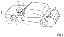
- the figure 9 represents very schematically another embodiment in which the accessory is a wheel of the vehicle.
- Fixing devices 3 then equip each wheel 8 of the vehicle, for example, by providing four devices by wheel. Alternatively, or may provide a single wheel lock at the center of the hub.
- FIG 9 schematically shows a socket 77 connected to the central 7.
- the central 7 is in fact an air distributor from the socket 77 in the various devices 3.
- An advantage of the embodiments that have been described is that it is now possible to simplify the removable attachment of a battery to a motor vehicle.
- Another advantage is that these embodiments can easily be supplemented by an anti-theft system.
- Another advantage is that the same removable mounting system can be used at the battery charging station.
Landscapes
- Chemical & Material Sciences (AREA)
- Engineering & Computer Science (AREA)
- Chemical Kinetics & Catalysis (AREA)
- Electrochemistry (AREA)
- General Chemical & Material Sciences (AREA)
- Combustion & Propulsion (AREA)
- Transportation (AREA)
- Mechanical Engineering (AREA)
- Arrangement Or Mounting Of Propulsion Units For Vehicles (AREA)
- Battery Mounting, Suspending (AREA)
Claims (13)
- Ein System zum entfernbaren Anbringen eines Zusatzteils (2) an ein Fahrzeug, das Folgendes aufweist:ein oder mehr entfernbare Anbringungsvorrichtungen (3), wobei jede Folgendes aufweist: ein Aufnahmeteil (5), das mit einem ersten Ausstattungsteil aus dem Zusatzteil und dem Fahrzeug assoziiert ist; ein Steckteil (4), das mit einem zweiten Ausstattungsteil aus dem Zusatzteil und dem Fahrzeug assoziiert ist, wobei der Steckteil einen vorstehenden Finger (40) aufweist, der zum Eingriff in eine Ausnehmung (52) des Aufnahmeteils vorgesehen ist; und ein Element (62, 62', 69) zum translatorischen Verriegeln des Fingers in der Ausnehmung, wobei der Finger eine ringförmige Nut (42) aufweist und das Verriegelungselement (62, 69) mit der Nut kooperiert, um den Finger translatorisch in der Ausnehmung (52) zu verriegeln;eine pneumatische Vorrichtung zum Betätigen jedes Verriegelungselements (62, 62', 69) zwischen einer entriegelten Position, in der der Finger (40) aus der Ausnehmung (52) herauskommen kann, und einer verriegelten Position, in der der Finger in der Ausnehmung translatorisch verriegelt ist, wobei ein Entriegeln die Gegenwart eines mechanischen oder elektronischen Schlüssels erfordert; undeine Schaltung zum Verteilen eines Fluides zwischen wenigstens einem Zugangspunkt (77), zugänglich von der Außenseite des Ausstattungsteils, das die Schaltung enthält, und dem Aufnahmeteil oder dem Steckteil, der in diesem Ausstattungsteil enthalten ist, von wenigstens einer Anbringungsvorrichtung, wobei Leckage- oder Schließventile in der Fluidverteilschaltung zwischen dem bzw. den Zugangspunkt/en und der bzw. den Anbringungsvorrichtung/en eingeführt sind,wobei die Leckage- oder Schließventile während einer Druckerzeugung, die von dem elektronischen oder mechanischen Schlüssel autorisiert sind, betätigt werden.
- System nach Anspruch 1, wobei ein gleicher Fluidzugangspunkt (77) von einer Vielzahl von Anbringungsvorrichtungen geteilt wird.
- System nach Anspruch 1 oder 2, wobei jede Betätigungsvorrichtung ein Element zur elastischen Rückkehr hin zu einer verriegelten Position der Anbringungsvorrichtung aufweist, die geeignet ist, pneumatisch in eine entriegelte Position vorgespannt zu werden.
- System nach einem der Ansprüche 1 bis 3, wobei das Zusatzteil eine Batterie oder eine Batterieanordnung ist.
- System nach einem der Ansprüche 1 bis 3, wobei das Zusatzteil ein Rad ist.
- System nach einem der Ansprüche 1 bis 5, wobei der Finger (40) einen Kreisquerschnitt besitzt.
- System nach einem der Ansprüche 1 bis 6, wobei das Verriegelungselement (62, 69) an der Aufnahmeteilseite angeordnet ist.
- System nach Anspruch 7, wobei das Verriegelungselement eine Stange (62) aufweist, die translatorisch senkrecht zu der Längsrichtung des Fingers (40) in der Ausnehmung (52) bewegt wird.
- System nach Anspruch 7, wobei das Verriegelungselement eine Klammer (69) aufweist, welche Arm-Enden besitzt, die vorgesehen sind, um in der verriegelten Position mit der Nut (42) in Eingriff zu kommen.
- System nach einem der Ansprüche 1 bis 6, wobei das Verriegelungselement (62, 69) an der Seite des Steckteils (4) angeordnet ist und wenigstens drei koplanare Bälle enthält, welche in der Nut des Fingers (40) gehalten werden, und zwar beweglich zwischen einer entriegelten Position, in der die Bälle in der Nut enthalten sind, und einer verriegelten Position, in der sie teilweise aus der Nut herauskommen.
- System nach einem der Ansprüche 1 bis 10, wobei das erste Ausstattungsteil das Fahrzeug ist und das zweite Ausstattungsteil das Zusatzteil (2) ist.
- Ein Ausstattungsteil aus einem Zusatzteil (2) und einem Fahrzeug, das Steckteile (4) aufweist, von Vorrichtungen zum entfernbaren Anbringen des Systems nach einem der Ansprüche 1 bis 11, im Wissen, dass die Fluidverteilschaltung des Systems in dem Ausstattungsteil enthalten ist.
- Ein Ausstattungsteil aus einem Zusatzteil (2) und einem Fahrzeug, das Aufnahmeteile (5) aufweist, von Vorrichtungen zum entfernbaren Anbringen des Systems nach einem der Ansprüche 1 bis 11, im Wissen, dass die Fluidverteilschaltung des Systems in dem Ausstattungsteil enthalten ist.
Applications Claiming Priority (2)
| Application Number | Priority Date | Filing Date | Title |
|---|---|---|---|
| FR1363555A FR3015774A1 (fr) | 2013-12-24 | 2013-12-24 | Systeme de fixation amovible d'une batterie a un support |
| PCT/EP2014/079222 WO2015097238A1 (fr) | 2013-12-24 | 2014-12-23 | Systeme de fixation amovible d'une batterie ou un ensemble de batteries a un vehicule |
Publications (2)
| Publication Number | Publication Date |
|---|---|
| EP3087625A1 EP3087625A1 (de) | 2016-11-02 |
| EP3087625B1 true EP3087625B1 (de) | 2018-09-05 |
Family
ID=50290066
Family Applications (1)
| Application Number | Title | Priority Date | Filing Date |
|---|---|---|---|
| EP14824002.1A Not-in-force EP3087625B1 (de) | 2013-12-24 | 2014-12-23 | System zur lösbaren befestigung einer batterie oder eines batteriepacks an einem fahrzeug |
Country Status (3)
| Country | Link |
|---|---|
| EP (1) | EP3087625B1 (de) |
| FR (1) | FR3015774A1 (de) |
| WO (1) | WO2015097238A1 (de) |
Cited By (3)
| Publication number | Priority date | Publication date | Assignee | Title |
|---|---|---|---|---|
| CN109533148A (zh) * | 2018-09-29 | 2019-03-29 | 江苏汇鑫新能源汽车科技有限公司 | 一种具有减震功能的电动车控制器安装架 |
| US20200343500A1 (en) * | 2019-04-23 | 2020-10-29 | Xing Power Inc. | Battery cartridge for vehicle |
| US11600880B2 (en) | 2020-09-01 | 2023-03-07 | Beta Air, Llc | System and method for securing battery in aircraft |
Families Citing this family (12)
| Publication number | Priority date | Publication date | Assignee | Title |
|---|---|---|---|---|
| GB2555826B (en) * | 2016-11-11 | 2019-11-20 | Jaguar Land Rover Ltd | Battery support arrangement |
| CN106427513B (zh) * | 2016-11-14 | 2019-03-26 | 合力叉车有限公司 | 一种抽屉式电动汽车的电池快速更换系统 |
| WO2018086132A1 (zh) * | 2016-11-14 | 2018-05-17 | 深圳市大疆创新科技有限公司 | 检测装置及无人机 |
| CN106979192B (zh) | 2016-12-12 | 2019-03-26 | 上海蔚来汽车有限公司 | 周向锁止机构、电池锁定装置、动力电池包及车辆 |
| WO2019016578A1 (en) * | 2017-07-18 | 2019-01-24 | Parandin Ehsan | INTERCHANGEABLE BATTERY FOR ELECTRIC VEHICLES (IBEV) AND IBEV STATION |
| CN108202589A (zh) * | 2017-11-21 | 2018-06-26 | 广州昌源环保科技有限公司 | 一种新型新能源汽车蓄电池装置 |
| SG11202006166VA (en) * | 2017-12-29 | 2020-07-29 | Shanghai Dianba New Energy Technology Co Ltd | Lock mechanism, lock system, quick exchange bracket assembly and electronic vehicle |
| DE102019202156A1 (de) | 2019-02-18 | 2020-08-20 | Audi Ag | Befestigungsanordnung, Toleranzausgleichsanordnung für eine Befestigungseinrichtung und Montageverfahren zum Befestigen eines Batteriemoduls an einer Kühlvorrichtung |
| CN110676404B (zh) * | 2019-09-06 | 2020-11-03 | 苏州科腾软件开发有限公司 | 一种新能源汽车用电池便捷锁紧装置及其工作方法 |
| CN114643849B (zh) * | 2020-12-17 | 2025-07-01 | 上海汽车集团股份有限公司 | 电动汽车电池包锁紧装置及电动汽车 |
| FR3141897A1 (fr) * | 2022-11-16 | 2024-05-17 | Psa Automobiles Sa | Vehicule automobile comprenant une batterie amovible et son controle mecanique de positionnement, et procede sur la base d’un tel vehicule |
| US12603376B2 (en) * | 2023-10-23 | 2026-04-14 | Alfred S. Fairbanks | Modular shareable battery system |
Family Cites Families (9)
| Publication number | Priority date | Publication date | Assignee | Title |
|---|---|---|---|---|
| FR1363555A (fr) | 1963-06-21 | 1964-06-12 | Chaudière de chauffage central | |
| DE2241548B1 (de) * | 1972-08-24 | 1973-10-31 | Messerschmitt-Boelkow-Blohm Gmbh, 8000 Muenchen | Einbauanordnung für die auswechselbaren Batterien eines Elektrofahrzeugs |
| GB2257673B (en) * | 1991-07-13 | 1995-07-05 | Lyndon Ketchen | Battery clamp |
| FR2933656B1 (fr) * | 2008-07-08 | 2010-12-03 | Renault Sas | Dispositif de verrouillage et deverouillage automatiques d'un bac batterie de vehicule automobile electrique, vehicule et station d'echange de batteries equipes d'un tel dispositif |
| FR2940638A3 (fr) * | 2008-12-30 | 2010-07-02 | Renault Sas | Vehicule automobile a moteur electrique alimente par une batterie amovible et procede de fixation d'une batterie sous la caisse d'un tel vehicule. |
| FR2954592B1 (fr) * | 2009-12-21 | 2012-01-06 | Renault Sa | Procede et syteme de montage ou demontage d'une batterie d'un vehicule automobile. |
| FR2954594B1 (fr) * | 2009-12-21 | 2012-01-13 | Renault Sa | Dispositif de fixation amovible d'une batterie d'un vehicule automobile |
| FR2958237B1 (fr) * | 2010-04-06 | 2016-02-05 | Akka Ingenierie Produit | Systeme de verrouillage pour rack batteries de vehicule electrique |
| US8936124B2 (en) * | 2010-04-08 | 2015-01-20 | Magna Steyr Fahrzeugtechnik Ag & Co Kg | Fastening device |
-
2013
- 2013-12-24 FR FR1363555A patent/FR3015774A1/fr not_active Withdrawn
-
2014
- 2014-12-23 WO PCT/EP2014/079222 patent/WO2015097238A1/fr not_active Ceased
- 2014-12-23 EP EP14824002.1A patent/EP3087625B1/de not_active Not-in-force
Cited By (5)
| Publication number | Priority date | Publication date | Assignee | Title |
|---|---|---|---|---|
| CN109533148A (zh) * | 2018-09-29 | 2019-03-29 | 江苏汇鑫新能源汽车科技有限公司 | 一种具有减震功能的电动车控制器安装架 |
| CN109533148B (zh) * | 2018-09-29 | 2020-10-16 | 江苏汇鑫新能源汽车科技有限公司 | 一种具有减震功能的电动车控制器安装架 |
| US20200343500A1 (en) * | 2019-04-23 | 2020-10-29 | Xing Power Inc. | Battery cartridge for vehicle |
| US11056746B2 (en) * | 2019-04-23 | 2021-07-06 | Xing Power Inc. | Battery cartridge for vehicle and locking mechanism |
| US11600880B2 (en) | 2020-09-01 | 2023-03-07 | Beta Air, Llc | System and method for securing battery in aircraft |
Also Published As
| Publication number | Publication date |
|---|---|
| FR3015774A1 (fr) | 2015-06-26 |
| WO2015097238A1 (fr) | 2015-07-02 |
| EP3087625A1 (de) | 2016-11-02 |
| WO2015097238A9 (fr) | 2015-08-13 |
Similar Documents
| Publication | Publication Date | Title |
|---|---|---|
| EP3087625B1 (de) | System zur lösbaren befestigung einer batterie oder eines batteriepacks an einem fahrzeug | |
| CA2523581C (fr) | Vehicule autonome a traction electrique | |
| FR2826626A1 (fr) | Module d'equipement d'un vehicule automobile | |
| BE1026121B1 (fr) | Bicyclette electrique | |
| FR3043596A1 (fr) | Vehicule terrestre de transport en commun a capotage superieur fonctionnel. | |
| FR2909952A1 (fr) | Antivol de vehicule comprenant un boitier equipe et procede de realisation dudit boitier. | |
| FR3120835A1 (fr) | Structure d'ancrage | |
| EP2532547B1 (de) | Fahrgestellstruktur zur Aufnahme eines Fahrzeuginnenraums eines Kraftfahrzeugs mit Elektroantrieb, und mit einer solchen Fahrgestellstruktur ausgestattetes Kraftfahrzeug | |
| FR3043622B1 (fr) | Dispositif de verrouillage d'un module de stockage d'energie electrique rechargeable et vehicule electrique muni d'un tel dispositif. | |
| FR3067298B1 (fr) | Ensemble pour chassis de vehicule hybride facilitant l'acces a un reservoir | |
| FR2856959A1 (fr) | Vehicule autonome a traction electrique | |
| FR3074452B1 (fr) | Ensemble pour chassis de vehicule hybride facilitant l'acces a un reservoir | |
| FR2949722A1 (fr) | Dispositif de support rabattable pour une face avant d'une porte d'un espace de rangement d'un tableau de bord de vehicule | |
| FR3049922B1 (fr) | Vehicule terrestre destine a un usage en libre service | |
| FR2984245A1 (fr) | Planche de bord pour un vehicule | |
| EP3233586B1 (de) | Diebstahlsicherung für eine lenksäule | |
| EP4649542A1 (de) | Batterievorrichtung, insbesondere für ein fahrzeug | |
| EP3046810B1 (de) | Vorderbau eines kraftfahzeugs mit elektrischer leitung | |
| FR3128438A1 (fr) | Plancher pour véhicule et coffre de véhicule comprenant un tel plancher | |
| FR2921316A1 (fr) | Systeme de rangement d'un boitier electronique dans une partie d'habitacle de vehicule automobile. | |
| FR2909944A1 (fr) | Agencement d'au moins un adaptateur comprenant un element de connexion a un appareil electronique | |
| FR2849125A1 (fr) | Ensemble a liaison rotulante, maitre-cylindre muni d'un tel ensemble, et procede de montage d'un tel ensemble | |
| EP2165888A1 (de) | Staufachmodul für C-Säule eines Kraftfahrzeugs | |
| FR2945894A1 (fr) | Dispositif de connexion d'une batterie | |
| FR2921318A1 (fr) | Systeme de rangement d'un boitier electronique orientable dans une partie d'habitacle de vehicule automobile. |
Legal Events
| Date | Code | Title | Description |
|---|---|---|---|
| PUAI | Public reference made under article 153(3) epc to a published international application that has entered the european phase |
Free format text: ORIGINAL CODE: 0009012 |
|
| 17P | Request for examination filed |
Effective date: 20160621 |
|
| AK | Designated contracting states |
Kind code of ref document: A1 Designated state(s): AL AT BE BG CH CY CZ DE DK EE ES FI FR GB GR HR HU IE IS IT LI LT LU LV MC MK MT NL NO PL PT RO RS SE SI SK SM TR |
|
| AX | Request for extension of the european patent |
Extension state: BA ME |
|
| DAX | Request for extension of the european patent (deleted) | ||
| STAA | Information on the status of an ep patent application or granted ep patent |
Free format text: STATUS: EXAMINATION IS IN PROGRESS |
|
| 17Q | First examination report despatched |
Effective date: 20170907 |
|
| GRAP | Despatch of communication of intention to grant a patent |
Free format text: ORIGINAL CODE: EPIDOSNIGR1 |
|
| STAA | Information on the status of an ep patent application or granted ep patent |
Free format text: STATUS: GRANT OF PATENT IS INTENDED |
|
| INTG | Intention to grant announced |
Effective date: 20180125 |
|
| GRAS | Grant fee paid |
Free format text: ORIGINAL CODE: EPIDOSNIGR3 |
|
| GRAJ | Information related to disapproval of communication of intention to grant by the applicant or resumption of examination proceedings by the epo deleted |
Free format text: ORIGINAL CODE: EPIDOSDIGR1 |
|
| GRAL | Information related to payment of fee for publishing/printing deleted |
Free format text: ORIGINAL CODE: EPIDOSDIGR3 |
|
| STAA | Information on the status of an ep patent application or granted ep patent |
Free format text: STATUS: EXAMINATION IS IN PROGRESS |
|
| INTC | Intention to grant announced (deleted) | ||
| GRAR | Information related to intention to grant a patent recorded |
Free format text: ORIGINAL CODE: EPIDOSNIGR71 |
|
| STAA | Information on the status of an ep patent application or granted ep patent |
Free format text: STATUS: GRANT OF PATENT IS INTENDED |
|
| GRAA | (expected) grant |
Free format text: ORIGINAL CODE: 0009210 |
|
| STAA | Information on the status of an ep patent application or granted ep patent |
Free format text: STATUS: THE PATENT HAS BEEN GRANTED |
|
| INTG | Intention to grant announced |
Effective date: 20180726 |
|
| AK | Designated contracting states |
Kind code of ref document: B1 Designated state(s): AL AT BE BG CH CY CZ DE DK EE ES FI FR GB GR HR HU IE IS IT LI LT LU LV MC MK MT NL NO PL PT RO RS SE SI SK SM TR |
|
| REG | Reference to a national code |
Ref country code: GB Ref legal event code: FG4D Free format text: NOT ENGLISH |
|
| REG | Reference to a national code |
Ref country code: CH Ref legal event code: EP |
|
| REG | Reference to a national code |
Ref country code: AT Ref legal event code: REF Ref document number: 1038886 Country of ref document: AT Kind code of ref document: T Effective date: 20180915 |
|
| REG | Reference to a national code |
Ref country code: IE Ref legal event code: FG4D Free format text: LANGUAGE OF EP DOCUMENT: FRENCH |
|
| REG | Reference to a national code |
Ref country code: DE Ref legal event code: R096 Ref document number: 602014031961 Country of ref document: DE |
|
| REG | Reference to a national code |
Ref country code: NL Ref legal event code: MP Effective date: 20180905 |
|
| REG | Reference to a national code |
Ref country code: LT Ref legal event code: MG4D |
|
| PG25 | Lapsed in a contracting state [announced via postgrant information from national office to epo] |
Ref country code: LT Free format text: LAPSE BECAUSE OF FAILURE TO SUBMIT A TRANSLATION OF THE DESCRIPTION OR TO PAY THE FEE WITHIN THE PRESCRIBED TIME-LIMIT Effective date: 20180905 Ref country code: BG Free format text: LAPSE BECAUSE OF FAILURE TO SUBMIT A TRANSLATION OF THE DESCRIPTION OR TO PAY THE FEE WITHIN THE PRESCRIBED TIME-LIMIT Effective date: 20181205 Ref country code: SE Free format text: LAPSE BECAUSE OF FAILURE TO SUBMIT A TRANSLATION OF THE DESCRIPTION OR TO PAY THE FEE WITHIN THE PRESCRIBED TIME-LIMIT Effective date: 20180905 Ref country code: FI Free format text: LAPSE BECAUSE OF FAILURE TO SUBMIT A TRANSLATION OF THE DESCRIPTION OR TO PAY THE FEE WITHIN THE PRESCRIBED TIME-LIMIT Effective date: 20180905 Ref country code: NO Free format text: LAPSE BECAUSE OF FAILURE TO SUBMIT A TRANSLATION OF THE DESCRIPTION OR TO PAY THE FEE WITHIN THE PRESCRIBED TIME-LIMIT Effective date: 20181205 Ref country code: RS Free format text: LAPSE BECAUSE OF FAILURE TO SUBMIT A TRANSLATION OF THE DESCRIPTION OR TO PAY THE FEE WITHIN THE PRESCRIBED TIME-LIMIT Effective date: 20180905 Ref country code: GR Free format text: LAPSE BECAUSE OF FAILURE TO SUBMIT A TRANSLATION OF THE DESCRIPTION OR TO PAY THE FEE WITHIN THE PRESCRIBED TIME-LIMIT Effective date: 20181206 |
|
| REG | Reference to a national code |
Ref country code: AT Ref legal event code: MK05 Ref document number: 1038886 Country of ref document: AT Kind code of ref document: T Effective date: 20180905 |
|
| PG25 | Lapsed in a contracting state [announced via postgrant information from national office to epo] |
Ref country code: LV Free format text: LAPSE BECAUSE OF FAILURE TO SUBMIT A TRANSLATION OF THE DESCRIPTION OR TO PAY THE FEE WITHIN THE PRESCRIBED TIME-LIMIT Effective date: 20180905 Ref country code: HR Free format text: LAPSE BECAUSE OF FAILURE TO SUBMIT A TRANSLATION OF THE DESCRIPTION OR TO PAY THE FEE WITHIN THE PRESCRIBED TIME-LIMIT Effective date: 20180905 Ref country code: AL Free format text: LAPSE BECAUSE OF FAILURE TO SUBMIT A TRANSLATION OF THE DESCRIPTION OR TO PAY THE FEE WITHIN THE PRESCRIBED TIME-LIMIT Effective date: 20180905 |
|
| PGFP | Annual fee paid to national office [announced via postgrant information from national office to epo] |
Ref country code: FR Payment date: 20181231 Year of fee payment: 5 |
|
| PG25 | Lapsed in a contracting state [announced via postgrant information from national office to epo] |
Ref country code: IS Free format text: LAPSE BECAUSE OF FAILURE TO SUBMIT A TRANSLATION OF THE DESCRIPTION OR TO PAY THE FEE WITHIN THE PRESCRIBED TIME-LIMIT Effective date: 20190105 Ref country code: ES Free format text: LAPSE BECAUSE OF FAILURE TO SUBMIT A TRANSLATION OF THE DESCRIPTION OR TO PAY THE FEE WITHIN THE PRESCRIBED TIME-LIMIT Effective date: 20180905 Ref country code: NL Free format text: LAPSE BECAUSE OF FAILURE TO SUBMIT A TRANSLATION OF THE DESCRIPTION OR TO PAY THE FEE WITHIN THE PRESCRIBED TIME-LIMIT Effective date: 20180905 Ref country code: EE Free format text: LAPSE BECAUSE OF FAILURE TO SUBMIT A TRANSLATION OF THE DESCRIPTION OR TO PAY THE FEE WITHIN THE PRESCRIBED TIME-LIMIT Effective date: 20180905 Ref country code: AT Free format text: LAPSE BECAUSE OF FAILURE TO SUBMIT A TRANSLATION OF THE DESCRIPTION OR TO PAY THE FEE WITHIN THE PRESCRIBED TIME-LIMIT Effective date: 20180905 Ref country code: IT Free format text: LAPSE BECAUSE OF FAILURE TO SUBMIT A TRANSLATION OF THE DESCRIPTION OR TO PAY THE FEE WITHIN THE PRESCRIBED TIME-LIMIT Effective date: 20180905 Ref country code: CZ Free format text: LAPSE BECAUSE OF FAILURE TO SUBMIT A TRANSLATION OF THE DESCRIPTION OR TO PAY THE FEE WITHIN THE PRESCRIBED TIME-LIMIT Effective date: 20180905 Ref country code: RO Free format text: LAPSE BECAUSE OF FAILURE TO SUBMIT A TRANSLATION OF THE DESCRIPTION OR TO PAY THE FEE WITHIN THE PRESCRIBED TIME-LIMIT Effective date: 20180905 Ref country code: PL Free format text: LAPSE BECAUSE OF FAILURE TO SUBMIT A TRANSLATION OF THE DESCRIPTION OR TO PAY THE FEE WITHIN THE PRESCRIBED TIME-LIMIT Effective date: 20180905 |
|
| PG25 | Lapsed in a contracting state [announced via postgrant information from national office to epo] |
Ref country code: SK Free format text: LAPSE BECAUSE OF FAILURE TO SUBMIT A TRANSLATION OF THE DESCRIPTION OR TO PAY THE FEE WITHIN THE PRESCRIBED TIME-LIMIT Effective date: 20180905 Ref country code: PT Free format text: LAPSE BECAUSE OF FAILURE TO SUBMIT A TRANSLATION OF THE DESCRIPTION OR TO PAY THE FEE WITHIN THE PRESCRIBED TIME-LIMIT Effective date: 20190105 Ref country code: SM Free format text: LAPSE BECAUSE OF FAILURE TO SUBMIT A TRANSLATION OF THE DESCRIPTION OR TO PAY THE FEE WITHIN THE PRESCRIBED TIME-LIMIT Effective date: 20180905 |
|
| REG | Reference to a national code |
Ref country code: DE Ref legal event code: R097 Ref document number: 602014031961 Country of ref document: DE |
|
| REG | Reference to a national code |
Ref country code: DE Ref legal event code: R119 Ref document number: 602014031961 Country of ref document: DE |
|
| PLBE | No opposition filed within time limit |
Free format text: ORIGINAL CODE: 0009261 |
|
| STAA | Information on the status of an ep patent application or granted ep patent |
Free format text: STATUS: NO OPPOSITION FILED WITHIN TIME LIMIT |
|
| PG25 | Lapsed in a contracting state [announced via postgrant information from national office to epo] |
Ref country code: DK Free format text: LAPSE BECAUSE OF FAILURE TO SUBMIT A TRANSLATION OF THE DESCRIPTION OR TO PAY THE FEE WITHIN THE PRESCRIBED TIME-LIMIT Effective date: 20180905 |
|
| REG | Reference to a national code |
Ref country code: CH Ref legal event code: PL |
|
| 26N | No opposition filed |
Effective date: 20190606 |
|
| GBPC | Gb: european patent ceased through non-payment of renewal fee |
Effective date: 20181223 |
|
| PG25 | Lapsed in a contracting state [announced via postgrant information from national office to epo] |
Ref country code: SI Free format text: LAPSE BECAUSE OF FAILURE TO SUBMIT A TRANSLATION OF THE DESCRIPTION OR TO PAY THE FEE WITHIN THE PRESCRIBED TIME-LIMIT Effective date: 20180905 Ref country code: LU Free format text: LAPSE BECAUSE OF NON-PAYMENT OF DUE FEES Effective date: 20181223 Ref country code: MC Free format text: LAPSE BECAUSE OF FAILURE TO SUBMIT A TRANSLATION OF THE DESCRIPTION OR TO PAY THE FEE WITHIN THE PRESCRIBED TIME-LIMIT Effective date: 20180905 |
|
| REG | Reference to a national code |
Ref country code: IE Ref legal event code: MM4A |
|
| REG | Reference to a national code |
Ref country code: BE Ref legal event code: MM Effective date: 20181231 |
|
| PG25 | Lapsed in a contracting state [announced via postgrant information from national office to epo] |
Ref country code: DE Free format text: LAPSE BECAUSE OF NON-PAYMENT OF DUE FEES Effective date: 20190702 Ref country code: IE Free format text: LAPSE BECAUSE OF NON-PAYMENT OF DUE FEES Effective date: 20181223 |
|
| PG25 | Lapsed in a contracting state [announced via postgrant information from national office to epo] |
Ref country code: BE Free format text: LAPSE BECAUSE OF NON-PAYMENT OF DUE FEES Effective date: 20181231 |
|
| PG25 | Lapsed in a contracting state [announced via postgrant information from national office to epo] |
Ref country code: CH Free format text: LAPSE BECAUSE OF NON-PAYMENT OF DUE FEES Effective date: 20181231 Ref country code: LI Free format text: LAPSE BECAUSE OF NON-PAYMENT OF DUE FEES Effective date: 20181231 Ref country code: GB Free format text: LAPSE BECAUSE OF NON-PAYMENT OF DUE FEES Effective date: 20181223 |
|
| PG25 | Lapsed in a contracting state [announced via postgrant information from national office to epo] |
Ref country code: MT Free format text: LAPSE BECAUSE OF FAILURE TO SUBMIT A TRANSLATION OF THE DESCRIPTION OR TO PAY THE FEE WITHIN THE PRESCRIBED TIME-LIMIT Effective date: 20180905 |
|
| PG25 | Lapsed in a contracting state [announced via postgrant information from national office to epo] |
Ref country code: TR Free format text: LAPSE BECAUSE OF FAILURE TO SUBMIT A TRANSLATION OF THE DESCRIPTION OR TO PAY THE FEE WITHIN THE PRESCRIBED TIME-LIMIT Effective date: 20180905 |
|
| PG25 | Lapsed in a contracting state [announced via postgrant information from national office to epo] |
Ref country code: HU Free format text: LAPSE BECAUSE OF FAILURE TO SUBMIT A TRANSLATION OF THE DESCRIPTION OR TO PAY THE FEE WITHIN THE PRESCRIBED TIME-LIMIT; INVALID AB INITIO Effective date: 20141223 Ref country code: CY Free format text: LAPSE BECAUSE OF FAILURE TO SUBMIT A TRANSLATION OF THE DESCRIPTION OR TO PAY THE FEE WITHIN THE PRESCRIBED TIME-LIMIT Effective date: 20180905 Ref country code: MK Free format text: LAPSE BECAUSE OF NON-PAYMENT OF DUE FEES Effective date: 20180905 |
|
| PG25 | Lapsed in a contracting state [announced via postgrant information from national office to epo] |
Ref country code: FR Free format text: LAPSE BECAUSE OF NON-PAYMENT OF DUE FEES Effective date: 20191231 |