EP3087793B1 - Netzwerksteuerungsvorrichtungen und verfahren zur durchführung einer drahtlosen kommunikation zwischen zwei kommunikationsvorrichtungen über mehrstufige signalisierungseinheiten - Google Patents
Netzwerksteuerungsvorrichtungen und verfahren zur durchführung einer drahtlosen kommunikation zwischen zwei kommunikationsvorrichtungen über mehrstufige signalisierungseinheiten Download PDFInfo
- Publication number
- EP3087793B1 EP3087793B1 EP15874738.6A EP15874738A EP3087793B1 EP 3087793 B1 EP3087793 B1 EP 3087793B1 EP 15874738 A EP15874738 A EP 15874738A EP 3087793 B1 EP3087793 B1 EP 3087793B1
- Authority
- EP
- European Patent Office
- Prior art keywords
- signaling
- entities
- entity
- communications
- communications apparatus
- Prior art date
- Legal status (The legal status is an assumption and is not a legal conclusion. Google has not performed a legal analysis and makes no representation as to the accuracy of the status listed.)
- Not-in-force
Links
- 230000011664 signaling Effects 0.000 title claims description 307
- 238000004891 communication Methods 0.000 title claims description 181
- 238000000034 method Methods 0.000 title claims description 34
- 230000005540 biological transmission Effects 0.000 claims description 30
- 238000012544 monitoring process Methods 0.000 claims description 11
- 230000008569 process Effects 0.000 claims description 6
- 238000012545 processing Methods 0.000 description 19
- 238000010586 diagram Methods 0.000 description 10
- 230000006870 function Effects 0.000 description 7
- 238000006243 chemical reaction Methods 0.000 description 6
- 238000005516 engineering process Methods 0.000 description 6
- 230000009131 signaling function Effects 0.000 description 5
- 230000001413 cellular effect Effects 0.000 description 4
- 238000010295 mobile communication Methods 0.000 description 4
- 230000007704 transition Effects 0.000 description 3
- 230000003213 activating effect Effects 0.000 description 2
- 230000009977 dual effect Effects 0.000 description 2
- 238000012546 transfer Methods 0.000 description 2
- 230000032258 transport Effects 0.000 description 2
- 230000002776 aggregation Effects 0.000 description 1
- 238000004220 aggregation Methods 0.000 description 1
- 230000004075 alteration Effects 0.000 description 1
- 230000010267 cellular communication Effects 0.000 description 1
- 239000004020 conductor Substances 0.000 description 1
- 238000013461 design Methods 0.000 description 1
- 230000010354 integration Effects 0.000 description 1
- 230000007774 longterm Effects 0.000 description 1
- 238000005259 measurement Methods 0.000 description 1
- 238000012986 modification Methods 0.000 description 1
- 230000004048 modification Effects 0.000 description 1
- 230000001360 synchronised effect Effects 0.000 description 1
Images


Classifications
-
- H—ELECTRICITY
- H04—ELECTRIC COMMUNICATION TECHNIQUE
- H04W—WIRELESS COMMUNICATION NETWORKS
- H04W56/00—Synchronisation arrangements
-
- H—ELECTRICITY
- H04—ELECTRIC COMMUNICATION TECHNIQUE
- H04L—TRANSMISSION OF DIGITAL INFORMATION, e.g. TELEGRAPHIC COMMUNICATION
- H04L5/00—Arrangements affording multiple use of the transmission path
- H04L5/003—Arrangements for allocating sub-channels of the transmission path
- H04L5/0053—Allocation of signalling, i.e. of overhead other than pilot signals
Definitions
- the invention relates to methods of performing wireless communications, and more particularly to methods of performing wireless communications between two communications apparatuses via multi-level signaling entities.
- wireless normally refers to an electrical or electronic operation that is accomplished without the use of a “hard wired” connection.
- Wireless communications is the transfer of information over a distance without the use of electrical conductors or wires. The distances involved may be short (a few meters for television remote controls) or very long (thousands or even millions of kilometers for radio communications).
- the best known example of wireless communications is the cellular telephone. Cellular telephones use radio waves to enable an operator to make phone calls to another party, from many locations worldwide. They can be used anywhere, as long as there is a cellular telephone site to house equipment that can transmit and receive signals, which are processed to transfer both voice and data to and from the cellular telephones.
- GSM Global System for Mobile communications
- TDMA time division multiple access
- CDMA2000 is a hybrid mobile communications 2.5G / 3G (generation) technology standard that uses code division multiple access (CDMA) technology.
- UMTS Universal Mobile Telecommunications System
- 3G mobile communications system which provides an enhanced range of multimedia services over the GSM system.
- Wireless Fidelity is a technology defined by the 802.11 engineering standard and can be used for home networks, mobile phones, and video games, to provide a high-frequency wireless local area network.
- the LTE (Long Term Evolution) and the LTE-Advanced evolved from the LTE are the 4G mobile communications systems, which provide high-speed data transmission over 2G and 3G systems.
- the invention suggests both a network control device having the features of claim 1 and a method of performing wireless communications between two communications apparatuses in a service network having the features of claim.
- An exemplary embodiment of a network control device comprises a controller and a wireless communications module.
- the controller provides a plurality of signaling entities each belonging to one of a plurality of signaling levels to form multi-level signaling entities, and configures one or more signaling entities of the multi-level signaling entities to a communications apparatus to communicate with the communications apparatus based on the one or more configured signaling entities.
- the wireless communications module transmits a plurality of radio frequency signals via the one or more configured signaling entities.
- An exemplary embodiment of a method of performing wireless communications between two communications apparatuses in a service network via a plurality of signaling entities comprises: providing, by a first communications apparatus, multi-level signaling entities comprising a plurality of signaling entities each belonging to one of a plurality of signaling levels; configuring, by the first communications apparatus, one or more signaling entities of the multi-level signaling entities to a second communications apparatus; and communicating, by the first communications apparatus, with the second communications apparatus via the one or more configured signaling entities.
- FIG. 1 is a block diagram illustrating a wireless communications system according to an embodiment of the invention.
- a communications apparatus 110 is wirelessly connected to a service network, such as the service network 120 shown in FIG. 1 , for obtaining wireless communications services.
- Operations of the service network 120 are in compliance with a predetermined communications protocol.
- the service network 120 may comprise one or more network control devices, such as the network control device 130, interfacing between one or more communications apparatuses and the core network, for providing wireless communications services to the communications apparatus 110.
- the service network 120 may also comprise one or more intermediate control nodes, such as the network control entity 150 shown in FIG. 1 , for controlling the operation of the one or more network control devices.
- the network control entity may be a Base Station Controller (BSC), or may be realized in a distributed manner without a centralized controller, or may be a part of a base station's functionality, or the likes, and may be responsible of activating/deactivating and configuring signaling entities (which will be further discussed in the following paragraphs) under its control.
- BSC Base Station Controller
- the network control device may be an evolved Node B (eNB), a Base Station (BS), a Base Station Controller (BSC), a Radio Network Controller (RNC), or the like.
- eNB evolved Node B
- BS Base Station
- BSC Base Station Controller
- RNC Radio Network Controller
- the network control device when the network control device is an eNB or a BS, the network control entity in the service network may be a BSC which can configure the network control devices.
- the communications apparatus 110 may be a terminal node wirelessly connected to the service network, such as User Equipment (UE).
- the communications apparatus 110 may comprise at least a wireless communications module 111 for performing the functionality of wireless transmission and reception to and from the service network 120.
- the wireless communications module 111 may comprise at least a baseband signal processing device (not shown) and a Radio Frequency (RF) signal processing device (not shown).
- the baseband signal processing device may contain multiple hardware devices to perform baseband signal processing, including Analog to Digital Conversion (ADC)/Digital to Analog Conversion (DAC), gain adjusting, modulation/demodulation, encoding/decoding, and so on.
- ADC Analog to Digital Conversion
- DAC Digital to Analog Conversion
- the RF signal processing device may receive RF wireless signals, process the RF wireless signal, and convert the RF wireless signals to baseband signals, which are to be processed by the baseband signal processing device, or receive baseband signals from the baseband signal processing device, convert the received baseband signals to RF wireless signals, which are later transmitted, and process RF wireless signals.
- the RF signal processing device may also contain multiple hardware devices to perform radio frequency conversion and RF signal processing.
- the RF signal processing device may comprise a mixer to multiply the baseband signals with a carrier oscillated in the radio frequency of the wireless communications system, where the radio frequency depends on the RAT in use.
- the communications apparatus 110 may comprise a controller 112 for controlling the operation of the wireless communications module 111 and functional components (not shown) such as a display unit and/or keypad serving as the MMI (man-machine interface), a storage unit storing data and program codes of applications or communications protocols, and other functional components.
- a controller 112 for controlling the operation of the wireless communications module 111 and functional components (not shown) such as a display unit and/or keypad serving as the MMI (man-machine interface), a storage unit storing data and program codes of applications or communications protocols, and other functional components.
- FIG. 2 shows a simplified block diagram of a network control device in the service network according to an embodiment of the invention.
- the network control device may be an evolved Node B (eNB), a Base Station (BS), a Base Station Controller (BSC), a Radio Network Controller (RNC), or the like, and may also be regarded as a communications apparatus for providing wireless communications services in the service network.
- eNB evolved Node B
- BS Base Station
- BSC Base Station Controller
- RNC Radio Network Controller
- the network control device 230 may also comprise at least a wireless communications module 231 for performing the functionality of wireless transmission and reception between one or more peer devices, such as the communications apparatus 110 shown in FIG. 1 , and the core network.
- the wireless communications module 231 may comprise a baseband signal processing device (not shown) and a Radio Frequency (RF) signal processing device (not shown).
- the baseband signal processing device may contain multiple hardware devices to perform baseband signal processing, including Analog to Digital Conversion (ADC)/Digital to Analog Conversion (DAC), gain adjusting, modulation/demodulation, encoding/decoding, and so on.
- the RF signal processing device may receive RF wireless signals, process the RF wireless signals, and convert the RF wireless signals to baseband signals, which are to be processed by the baseband signal processing device, or receive baseband signals from the baseband signal processing device, convert the received baseband signals to RF wireless signals, which are later transmitted, and process RF wireless signals.
- the RF signal processing device may also contain multiple hardware devices to perform radio frequency conversion.
- the RF signal processing device may comprise a mixer to multiply the baseband signals with a carrier oscillated in the radio frequency of the wireless communications system, where the radio frequency depends on the RAT in use.
- the network control device 230 may comprise a controller 232 for controlling the operation of the wireless communications module 231 and other functional components (not shown), such as a storage unit storing data and program codes of applications or communications protocols, or others.
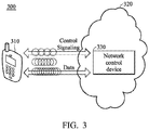
- FIG. 3 is a schematic diagram illustrating the concept of performing wireless communications in a wireless communications system via a plurality of signaling entities according to an embodiment of the invention.
- a communications apparatus such as a UE 310
- a service network such as the service network 320
- the service network 320 may comprise one or more network control devices, such as the network control device 330, interfacing between one or more communications apparatuses and the core network, for providing wireless communications services to the UE 310.
- a controller (such as the controller 232 shown in FIG. 2 ) of the network control device 330 is capable of providing a plurality of signaling entities, which are represented by the circles shown in FIG. 3 .
- the signaling entities are utilized as transmission mediums in the wireless communications system.
- the signaling entities provided by the network control device 330 may be regarded as "associated with" the network control device 330.
- each signaling entity may belong to one of a plurality of signaling levels to form multi-level signaling entities.
- the signaling levels may be hierarchical signaling levels.
- the controller of the network control device 330 may further configure one or more signaling entities of the multi-level signaling entities to a communications apparatus, such as the UE 310 shown in FIG. 3 , to communicate with the communications apparatus based on the one or more configured signaling entities by transmitting a plurality of radio frequency signals via the one or more configured signaling entities by the wireless communications module (such as the wireless communications module 231 shown in FIG. 2 ) of the network control device 330. As shown in FIG. 3 , the control signaling and data are transmitted via the signaling entities configured to the UE 310.
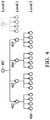
- FIG. 4 is a schematic diagram illustrating a tree-like structure of the proposed multi-level signaling entities according to an embodiment of the invention.
- each circle represents a signaling entity.
- There are three signaling levels shown in FIG. 4 including Level 0, Level 1 and Level 2.
- an ancestor (lineal ancestor) signaling entity in one signaling level may comprise one or more descendant signaling entities in a subsequent signaling level.
- the signaling entity 401 in Level 0 may comprise descendant signaling entities 402, 403, 404 and 405 in Level 1.
- the signaling level Level 0 may also be regarded as the ancestor signaling level of the signaling level Level 1, and the signaling level Level 1 may also be regarded as the descendant signaling level of the signaling level Level 0.
- a signaling entity is a child to at most one parent signaling entity.
- the signaling entity 402 is a child to at most one parent signaling entity 401
- the signaling entity 406 is a child to at most one parent signaling entity 402.
- the multi-level signaling entities may be characterized by one or more of a plurality of physical layer attributes comprising a carrier frequency for communications, a time interval for communications, a frequency band for communications, and a resolution and/or a radio coverage area for communications and transmission power for communications.
- the time interval and the frequency band may be the resources provided for the communications to take place.
- the signaling entities in different signaling levels may have different resolutions. Each signaling level may have a corresponding resolution. At least one signaling entity is formed within one signaling level.
- the radio coverage area may be defined by, for example, the 3dB beamwidth and the orientation of a beam when each signaling entity is a beam and may result from beamforming originating from the same location or transmission from a different location.
- the physical layer attributes of the signaling entities at different signaling levels may be further characterized by a radio coverage area of an ancestor signaling entity encompassing radio coverage area(s) of its descendant signaling entity ⁇ entities.
- the physical layer attributes of the signaling entities at different signaling levels may be further characterized by the transmission gain of one signaling entity being greater than the transmission gain of its ancestor signaling entity.
- the physical layer attributes of the signaling entities at different signaling levels may be further characterized by a radio coverage area of one signaling entity being more focused than a radio coverage area of its ancestor signaling entity.
- the hierarchical signaling levels may further be characterized by a transmission utilizing one or more signaling entities in one signaling level being more robust than a transmission utilizing one or more signaling entities at its descendant signaling level.
- the hierarchical signaling levels may further be characterized in that transmission utilizing one or more signaling entities in one signaling level may be more efficient than utilizing one or more signaling entities in its ancestor signaling level. Therefore, in some embodiments of the invention, when one signaling entity is configured to transmit control signaling, its descendant signaling entity ⁇ entities may be further configured to transmit data.
- FIG. 5 shows a flow chart of a method of performing wireless communications between two communications apparatuses in a service network via a plurality of signaling entities according to an embodiment of the invention.
- a first communications apparatus such as the network control device 130, 230 and/or 330
- the multi-level signaling entities may comprise a plurality of signaling entities each belonging to one of a plurality of signaling levels.
- the first communications apparatus may configure one or more signaling entities of the multi-level signaling entities to a second communications apparatus (such as the communications apparatus 110 and/or the UE 310) (Step S504).
- the configured signaling entities may belong to the same or different signaling levels.
- the first communications apparatus may communicate with the second communications apparatus via the one or more configured signaling entities (Step S506).
- each signaling entity may provide at least one of the following functions through the resources available to the signaling entity, the functionalities may comprise: 1). A synchronization service to facilitate a communications apparatus to affix to one or more signaling entity so as to utilize the services provided by the signaling entity, 2). Measurement signaling allowing a communications apparatus to determine the quality of service provided by the signaling entity, 3). A data channel that transports data to and from a communications apparatus, and 4). Control signaling between two communications apparatuses facilitating the data transport and the transition of the communications apparatus from currently affixed signaling entities to another set of affixed signaling entities.
- a communications apparatus may communicate with another communications apparatus in the service network through services and functions provided by one or more signaling entities.
- the resources available to the signaling entity may comprise at least the time interval in the time domain, the frequency band in the frequency domain, orientation of a beam in the spatial domain, power, and the code utilized for communications. Allocation of these resources to the various services may be pre-determined and understood by the communicating apparatuses, blindly detected by the communicating apparatuses, dynamically configured by a network control device and signaled by control signaling of the current signaling entity or one or more ancestor signaling entities of the current signaling entity, or a semi-static configuration signaled by higher-layer protocol (for example, Radio Resource Control (RRC) in LTE).
- RRC Radio Resource Control
- the physical layer resources may be utilized by the various services in a contention manner.
- a communications apparatus (such as the communications apparatus 110 and/or the UE 310) may operate in one of the following states with respect to a signaling entity, comprising a synchronized state, a monitoring state, an affixed state and a dissociated state.
- FIG. 6 is a schematic diagram showing the states of a communications apparatus and the corresponding state transition according to an embodiment of the invention.
- the communications apparatus may receive one or more radio frequency signals transmitted by the network control device (such as the network control device 130, 230 and/or 330) via at least one signaling entity to synchronize time and frequency with the network control device. After synchronizing time and frequency with the network control device, the communications apparatus is able to extract the radio resources and read the contents carried by the resources.
- the network control device such as the network control device 130, 230 and/or 330
- the communications apparatus may further monitor certain radio characteristics, such as channel quality, of one or more radio frequency signals transmitted by the network control device via at least one signaling entity to measure quality of service provided by the signaling entity.
- certain radio characteristics such as channel quality
- the communications apparatus in the affixed state, may affix to at least one signaling entity provided by the network control device so as to utilize one or more service(s) provided by the signaling entity. After affixing to the at least one signaling entity, two-way control signaling is established between the communications apparatus and the network control device. In other words, the communications apparatus has the ability to establish a two-way communications with the network control device after affixing to the at least one signaling entity.
- the communications apparatus may experience loss of synchronization or the cessation of an attempt to synchronize to a previously affixed signaling entity.
- the communications apparatus is able to directly utilize one or more descendant signaling entity ⁇ entities of the affixed signaling entity for communications without affixing to the one or more descendant signaling entity ⁇ entities.
- the communications apparatus can utilize the data channel provided by a signaling entity without being affixed to it. Only synchronization is required to establish the data channel and the control signaling for the data transmission can come from a different signaling entity, such as an ancestor signaling entity of that signaling entity.
- the communications apparatus may further monitor signal quality of an ancestor, a descendant or a sibling signaling entity of the currently affixed signaling entity. Furthermore, the communications apparatus may further continuously monitor signal quality of the currently affixed signaling entity and signal quality of relevant detectable signaling entities, such as an ancestor, a descendant or a sibling signaling entity of the affixed signaling entity, or a signaling entity within proximal radio coverage area of a currently affixed signaling entity during a process of communicating with the network control device.
- the monitoring of relevant detectable signaling entities may comprise measuring the quality of service and synchronization of the monitored signaling entities and/or the establishment of the ability to read control channels in the monitored signaling entities.
- the communications apparatus may enter the wireless communications protocol by first affixing to one or more of the signaling entities in an entry signaling level.
- the communications apparatus may select the preferred entry signaling level based on the previous entry experience of the communications apparatus.
- the communications apparatus may camp on or attach to the network control devices associated with the affixed one or more signaling entities and thereby establishes the entry into the service network.
- FIG. 7 shows a flow chart of a procedure for performing wireless communications in a service network according to an embodiment of the invention.
- the communications apparatus may enter the protocol of the wireless communications by affixing to at least one signaling entity in at least one entry signaling level (Step S702). After entering the protocol by affixing to at least one signaling entity in at least one entry signaling level, the communications apparatus may then establish at least one data channel in the affixed signaling entity or one of its descendant signaling entities. The establishment of a data channel is facilitated by the control signaling of the currently affixed signaling entity.
- the communicating device may continuously monitor relevant detectable signaling entities and determine, in conjunction with the network control device, whether reconfiguring one or more signal entities is needed based on the monitoring results (Step S704). That is, the communications apparatus may determine, in conjunction with the network control device, whether to synchronize to, monitor, affix to or dissociate from a signaling entity. When reconfiguring one or more signal entities is needed, the network control device may reconfigure one or more signal entities and the communications apparatus may then synchronize to, monitor and affix to the one or more reconfigured signal entities.
- the communications apparatus may determine whether data transmission is required (Step S706). For example, whether there is any data packet that needs to be transmitted. When data transmission is not required, the procedure returns to step S704 to keep monitoring relevant detectable signaling entities.
- the network control device may configure or reconfigure one or more signaling entities for data channels (Step S708), and the data transmission may begin (Step S710).
- the communications apparatus may further determine whether there is more data to be transmitted (Step S712). When there is no more data to be transmitted, the procedure returns to step S704 to keep monitoring relevant detectable signaling entities. When there is still some data to be transmitted, the communications apparatus may keep monitoring the currently utilized signaling entity (Step S714) to report the monitoring results to the network control device, and the procedure returns to step S708 for configuration or reconfiguration.
- the multi-level signal entities may be the transmission beams generated by the network control device and utilized for beamforming.
- An exemplary scenario of wireless communications utilizing multi-level beams will be illustrated in the following paragraphs.
- FIG. 8 shows exemplary multi-level beams generated by network control devices in the service network according to an embodiment of the invention.
- there may be two network control devices in the service network one is a macro cell 830 and the other one is a small cell 835.
- the macro cell 830 accompanied with the small cell 835 may generate several beams with different beam widths in different signaling levels.
- the hexagon 801 may represent a radio coverage area of the beam(s) generated by the macro cell 830, the beams 802-1 ⁇ 802-3 and 803-1 ⁇ 803-7 are the beams generated by the small cell 835.
- the radio coverage areas of the beams generated by the macro cell 830 and the small cell 835 may be different, where the radio coverage area may be defined by, for example, the 3dB beam width and the orientation of the beam.
- the beam(s) generated by the macro cell 830 may belong to the first signaling level Level 0.
- the beams 802-1 ⁇ 802-3 generated by the small cell 835 may belong to the second signaling level Level 1
- the beams 803-1 ⁇ 803-7 generated by the small cell 835 may belong to the third signaling level Level 2. Therefore, each level of beam has different beam widths.
- the focus areas of higher level beams lie within the focus area of a lower level beam (that is, the beam belonging to the signaling level with a relatively smaller number).
- the network control device(s) are responsible for activating/deactivating and configuring signaling entities under its control.
- the lower level beams provide certain control signaling functions to facilitate more efficient data communications over higher level beams. For example, when the first signaling level Level 0 is an entry signaling level, the beams in the first signaling level Level 0 may provide certain control signaling functions and the beams in the second signaling level Level 1 and/or the beams in the third signaling level Level 2 may provide data channel(s) for data transmission.
- the beams in the second signaling level Level 1 may provide certain control signaling functions and the beams in the third signaling level Level 2 may provide data channel(s) for data transmission.
- the signaling level providing control signaling functions may comprises multiple control beams as its child signaling entities.
- an entry signaling level may function without its ancestor signaling level.
- the second signaling level Level 1 when the second signaling level Level 1 is an entry signaling level, the second signaling level Level 1 may function without the first signaling level Level 0.
- a communications apparatus (such as the communications apparatus 110 and/or the UE 310) may further affix to the signal entity in an ancestor signaling level of an entry signaling level after affixing to the signal entity in the entry signaling level, or may determine not to affix to the signal entity in an ancestor signaling level of an entry signaling level.
- multi-level signaling entities by utilizing the multi-level signaling entities, generalization and combination of dual connectivity (for example, for a communications apparatus camping on both a macro cell and a small cell for communications as shown in FIG. 8 ) and carrier aggregation may be achieved.
- integration of dual connectivity with multi-level signaling entities into a single framework may also be achieved.
- the number of hierarchical signaling levels is not limited to any specific number.
- level skipping is workable. For example, in the embodiment shown in FIG.
- the beams in the first signaling level Level 0 may provide certain control signaling functions and the beams in the third signaling level Level 2 may provide data channel(s) for data transmission.
- there may be more than one signaling entity providing data channels multiple signaling entities configured for one communications apparatus with only one ancestor signaling entity providing control signaling or with more than one signaling entity (in the same level or an ancestral level to the data channel) providing control signaling.
- different physical layer attributes can be artificially generated based on the same physical channel.
- the signaling entities with different beam-widths may have the same ancestor signaling entity.
- the signaling entities in the same or different wireless communications framework may be integrated and wireless communications can be performed more robustly and more efficiently than before.
- any component or collection of components that perform the functions described above can be generically considered as one or more processors that control the discussed above function.
- the one or more processors can be implemented in numerous ways, such as with dedicated hardware, or with general purpose hardware that is programmed using microcode or software to perform the functions recited above.
Landscapes
- Engineering & Computer Science (AREA)
- Signal Processing (AREA)
- Computer Networks & Wireless Communication (AREA)
- Mobile Radio Communication Systems (AREA)
Claims (18)
- Netzwerksteuerungsvorrichtung (130;230;330;830;830;835), aufweisend:eine Steuerung (112;232), die eine Vielzahl von Signalisierungseinheiten bereitstellt, die jeweils zu einer aus einer Vielzahl von Signalisierungsebenen gehören, um mehrstufige Signalisierungseinheiten zu bilden, und um eine oder mehrere Signalisierungseinheiten der mehrstufigen Signalisierungseinheiten in Bezug auf eine Kommunikationsvorrichtung (110;310) zu konfigurieren (708), um mit der Kommunikationsvorrichtung (110;310) basierend auf der einen oder mehreren konfigurierten Signalisierungseinheiten zu kommunizieren; undein drahtloses Kommunikationsmodul (231), das eine Vielzahl von Hochfrequenzfunksignalen über die einen oder mehreren konfigurierten Signalisierungseinheiten sendet (710),wobei die Signalisierungseinheiten die zur Strahlformung verwendeten Übertragungsstrahlen (802-1∼802-3;803-1∼803-7) sind, und wobei die Signalisierungseinheiten in verschiedenen Signalisierungsebenen die Übertragungsstrahlen (802-1∼802-3;803-1∼803-7) mit unterschiedlichen Strahlbreiten sind,dadurch gekennzeichnet, dassdie Kommunikationsvorrichtung (110;310) angepasst ist, um in ein drahtloses Kommunikationsprotokoll einzutreten, indem sie zuerst an mindestens einer Signalisierungseinheit angebracht (702) wird, die von der Netzwerksteuerungsvorrichtung (130;230;330;830;835) in einem Eingangssignalisierungspegel bereitgestellt wird, um einen oder mehrere Dienste zu nutzen, die von der mindestens einen Signalisierungseinheit bereitgestellt werden; unddie Signalisierungseinheiten (401;402∼405;406) in verschiedenen Signalisierungsebenen eine hierarchische, baumartige Struktur bilden, bei der eine erste Signalisierungseinheit (401), die eine erste Strahlbreite in einer Signalisierungsebene aufweist, eine oder mehrere zweite Signalisierungseinheiten (402~405) in einer nachfolgenden Signalisierungsebene aufweist, die eine zweite Strahlbreite aufweisen, die schmaler ist als die erste Strahlbreite, wobei jeweils die erste Signalisierungseinheit ein Vorgänger der zweiten Signalisierungseinheit ist und die eine oder mehreren zweiten Signalisierungseinheiten (402~405) Nachfolger der ersten Signalisierungseinheit in der hierarchischen Struktur sind, unddie Signalisierungseinheiten in verschiedenen Signalisierungsebenen der Kommunikationsvorrichtung (110;310) bereitgestellt werden, damit diese in die Lage versetzt wird, auf der Netzwerksteuerungsvorrichtung (130;230;330;830;835) zu lagern oder sich an diese anzuschließen, indem sie an den Signalisierungseinheiten in verschiedenen Signalisierungsebenen befestigt wird.
- Netzwerksteuerungsvorrichtung (130;230;330;830;835) nach Anspruch 1, bei der die Signalisierungseinheiten durch ein oder mehrere von mehreren physikalischen Schichtattributen gekennzeichnet sind, die eine Trägerfrequenz für Kommunikationen, ein Zeitintervall für Kommunikationen, ein Frequenzband für Kommunikationen, einen Funkdeckungsbereich für Kommunikationen und eine Sendeleistung für Kommunikationen umfassen.
- Netzwerksteuerungsvorrichtung (130;230;330;830;835) nach Anspruch 1, bei der ein Funkabdeckungsbereich einer ersten Signalisierungseinheit mit einer ersten Strahlbreite die Funkabdeckungsfläche(n) der zweiten Signalisierungseinheit(en) umfasst, die von der ersten Signalisierungseinheit abstammt/abstammen, wobei die zweiten Signalisierungseinheit(en) eine zweite Strahlbreite aufweist/aufweisen, die schmaler als die erste Strahlbreite ist.
- Netzwerksteuerungsvorrichtung (130;230;330;830;835) nach Anspruch 1, bei der eine Übertragungsverstärkung der zweiten Signalisierungseinheit größer als eine Übertragungsverstärkung der ersten Signalisierungseinheit ist.
- Netzwerksteuerungsvorrichtung (130;230;330;830;835) nach Anspruch 1, bei der, wenn die erste Signalisierungseinheit konfiguriert ist, um Steuersignale an die Kommunikationsvorrichtung (110;310) zu übertragen, die eine oder die mehreren zweiten Signalisierungseinheiten (402∼405) des Weiteren konfiguriert ist/sind, um Daten an die Kommunikationsvorrichtung (110;310) zu übertragen.
- Verfahren zum Durchführen einer drahtlosen Kommunikation zwischen zwei Kommunikationsvorrichtungen (110;310;130;230;330;830;835) in einem Dienstnetzwerk (120;320) über eine Vielzahl von Signalisierungselementen, aufweisend:Bereitstellen von mehrstufigen Signalisierungseinheiten, die eine Vielzahl von Signalisierungseinheiten umfassen, die jeweils zu einer von mehreren Signalisierungsebenen gehören, durch eine erste Kommunikationsvorrichtung (130;230;330;830;835);Konfigurieren (708) einer oder mehrerer Signalisierungseinheiten der mehrstufigen Signalisierungseinheiten in Bezug auf eine zweite Kommunikationsvorrichtung (110;310) durch die erste Kommunikationsvorrichtung (130;230;330;830;835); undKommunizieren (710) durch die erste Kommunikationsvorrichtung (130;230;330;830;835) mit der zweiten Kommunikationsvorrichtung (110;310) über die eine oder die mehreren konfigurierten Signalisierungseinheiten,wobei die Signalisierungseinheiten die Übertragungsstrahlen (802-1∼802-3;803-1∼803-7) sind, die zur Strahlformung verwendet werden, und wobei die Signalisierungseinheiten in verschiedenen Signalisierungsebenen die Übertragungsstrahlen (802-1∼802-3;803-1∼803-7) mit unterschiedlichen Strahlbreiten sind,dadurch gekennzeichnet, dassdas Verfahren des Weiteren aufweist:Eintreten in ein drahtloses Kommunikationsprotokoll durch erstes Anbringen (702), durch die zweite Kommunikationsvorrichtung (110;310), an mindestens eine Signalisierungseinheit, die von der ersten Kommunikationsvorrichtung (130;230;330;830;835) in einem Eingangssignalpegel bereitgestellt wird, um einen oder mehrere Dienste zu nutzen, der/die von der mindestens einen Signalisierungseinheit bereitgestellt wird/werden; unddie Signalisierungseinheiten (401;402∼405;406) in verschiedenen Signalisierungsebenen, die eine hierarchische, baumartige Struktur bilden, wobei eine erste Signalisierungseinheit (401) eine erste Strahlbreite in einer Signalisierungsebene aufweist, eine oder mehrere zweite Signalisierungseinheiten (402∼405) in einer nachfolgenden Signalisierungsebene mit einer zweiten Strahlbreite aufweist/aufweisen, die schmaler als die erste Strahlbreite ist, wobei jeweils die erste Signalisierungseinheit ein Vorgänger der zweiten Signalisierungseinheit und die zweite Signalisierungseinheit ein Nachfolger der ersten Signalisierungseinheit in der hierarchischen Struktur ist, unddie Signalisierungseinheiten in verschiedenen Signalisierungsebenen der zweiten Kommunikationsvorrichtung (110;310) bereitgestellt werden, damit sie in die Lage versetzt wird, auf der ersten Kommunikationsvorrichtung (130;230;330;830;835) zu lagern oder sich an diese anzuschließen, indem sie an den Signalisierungseinheiten in verschiedenen Signalisierungsebenen befestigt wird.
- Verfahren nach Anspruch 6, bei dem die Signalisierungseinheiten durch eine oder mehrere aus einer Vielzahl von physikalischen Schichtattributen gekennzeichnet sind, die eine Trägerfrequenz für die Kommunikation, ein Zeitintervall für die Kommunikation, ein Frequenzband für die Kommunikation, einen Funkdeckungsbereich für die Kommunikation und eine Sendeleistung für die Kommunikation aufweisen.
- Verfahren nach Anspruch 6, bei dem ein Funkdeckungsbereich einer ersten Signalisierungseinheit mit einer ersten Strahlbreite die Funkdeckungsfläche(n) der zweiten Signalisierungseinheit(en) umfasst, die von der ersten Signalisierungseinheit abstammt/abstammen, wobei die zweiten Signalisierungseinheit(en) eine zweiten Strahlbreite aufweist/aufweisen, die schmaler als die erste Strahlbreite ist.
- Verfahren nach Anspruch 6, bei dem eine Übertragungsverstärkung der zweiten Signalisierungseinheit größer als eine Übertragungsverstärkung der ersten Signalisierungseinheit ist.
- Verfahren nach Anspruch 6, bei dem, wenn die erste Signalisierungseinheit konfiguriert ist, um Steuersignale an die zweite Kommunikationsvorrichtung (110;310) zu übertragen, die zweite(n) Signalisierungseinheit(en) des Weiteren konfiguriert ist/sind, um Daten an die zweite Kommunikationsvorrichtung (110;310) zu übertragen.
- Verfahren nach Anspruch 6, des Weiteren aufweisend:
Empfangen von einem oder mehreren Hochfrequenzsignalen, die von der ersten Kommunikationsvorrichtung (130;230;330;830;835) über mindestens eine Signalisierungseinheit übertragen werden, durch die zweite Kommunikationsvorrichtung (110;310), um Zeit und Frequenz mit der ersten Kommunikationsvorrichtung (130;230;330;830;835) zu synchronisieren. - Verfahren nach Anspruch 6, des Weiteren aufweisend:
Überwachen der Qualität eines oder mehrerer Hochfrequenzsignale, die von der ersten Kommunikationsvorrichtung (130;230;330;830;835) über mindestens eine Signalisierungseinheit übertragen werden, durch die zweite Kommunikationsvorrichtung (110;310), um eine von der Signalisierungseinheit bereitgestellte Dienstqualität zu messen. - Verfahren nach Anspruch 6, bei dem die zweite Kommunikationsvorrichtung (110;310) in der Lage ist, eine oder mehrere Signalisierungseinheiten, die in der befestigten Signalisierungseinheit enthalten sind, direkt für Kommunikationen zu verwenden, ohne an der einen oder mehreren Signalisierungseinheiten befestigt zu sein.
- Verfahren nach Anspruch 6, bei dem nach dem Anbringen an der mindestens einen Signalisierungseinheit eine Zwei-Wege-Steuersignalisierung zwischen der ersten Kommunikationsvorrichtung (130;230;330;830;835) und der zweiten Kommunikationsvorrichtung (110;310) hergestellt wird.
- Verfahren nach Anspruch 6, des Weiteren aufweisend:
Überwachen der Signalqualität mindestens einer Signalisierungseinheit, die sich von der angebrachten Signalisierungseinheit unterscheidet, durch die zweite Kommunikationsvorrichtung (110;310). - Verfahren nach Anspruch 6, des Weiteren aufweisend:
kontinuierliches Überwachen der Signalqualität der angebrachten Signalisierungseinheit und der Signalqualität mindestens einer Signalisierungseinheit, die sich von der angebrachten Signalisierungseinheit unterscheidet, durch die zweite Kommunikationsvorrichtung (110;310) während eines Kommunikationsprozesses mit der ersten Kommunikationsvorrichtung (130;230;330;830;835). - Verfahren nach Anspruch 6, des Weiteren aufweisend:
Auswählen eines bevorzugten Eingangssignalpegels durch die zweite Kommunikationsvorrichtung (110;310) aus einer Vielzahl von vordefinierten Eingangssignalpegeln vor dem ersten Anbringen an einer Signalisierungseinheit. - Verfahren nach Anspruch 17, bei dem der bevorzugte Eingangssignalpegel durch die zweite Kommunikationsvorrichtung (110;310) basierend auf früheren Eingangserfahrungen der zweiten Kommunikationsvorrichtung (110;310) ausgewählt wird.
Applications Claiming Priority (3)
| Application Number | Priority Date | Filing Date | Title |
|---|---|---|---|
| US201462097370P | 2014-12-29 | 2014-12-29 | |
| US14/623,117 US20160192365A1 (en) | 2014-12-29 | 2015-02-16 | Network control devices and methods of performing wireless communications between two communications apparatuses via multi-level signaling entities |
| PCT/CN2015/078765 WO2016107045A1 (en) | 2014-12-29 | 2015-05-12 | Network control devices and methods of performing wireless communications between two communications apparatuses via multi-level signaling entities |
Publications (3)
| Publication Number | Publication Date |
|---|---|
| EP3087793A1 EP3087793A1 (de) | 2016-11-02 |
| EP3087793A4 EP3087793A4 (de) | 2017-08-09 |
| EP3087793B1 true EP3087793B1 (de) | 2018-12-12 |
Family
ID=56166013
Family Applications (1)
| Application Number | Title | Priority Date | Filing Date |
|---|---|---|---|
| EP15874738.6A Not-in-force EP3087793B1 (de) | 2014-12-29 | 2015-05-12 | Netzwerksteuerungsvorrichtungen und verfahren zur durchführung einer drahtlosen kommunikation zwischen zwei kommunikationsvorrichtungen über mehrstufige signalisierungseinheiten |
Country Status (5)
| Country | Link |
|---|---|
| US (1) | US20160192365A1 (de) |
| EP (1) | EP3087793B1 (de) |
| CN (1) | CN107079484A (de) |
| BR (1) | BR112016017338A2 (de) |
| WO (1) | WO2016107045A1 (de) |
Family Cites Families (28)
| Publication number | Priority date | Publication date | Assignee | Title |
|---|---|---|---|---|
| US6741868B1 (en) * | 1999-07-30 | 2004-05-25 | Curitell Communications Inc. | Method and apparatus for interfacing among mobile terminal, base station and core network in mobile telecommunications system |
| US7529525B1 (en) * | 2002-04-16 | 2009-05-05 | Faulkner Interstices Llc | Method and apparatus for collecting information for use in a smart antenna system |
| US7433368B2 (en) * | 2003-12-11 | 2008-10-07 | Nokia Corporation | Signaling transport converter |
| US7379446B2 (en) * | 2004-10-14 | 2008-05-27 | Qualcomm Incorporated | Enhanced beacon signaling method and apparatus |
| US7756548B2 (en) * | 2005-09-19 | 2010-07-13 | Qualcomm Incorporated | Methods and apparatus for use in a wireless communications system that uses a multi-mode base station |
| CN101401382B (zh) * | 2006-01-10 | 2012-03-21 | 艾利森电话股份有限公司 | 用于在传输中过滤数据分组的方法和装置 |
| US7760751B2 (en) * | 2006-05-19 | 2010-07-20 | Futurewei Technologies, Inc. | System for supporting consecutive and distributed subcarrier channels in OFDMA networks |
| DE602006010606D1 (de) * | 2006-06-02 | 2009-12-31 | Ericsson Telefon Ab L M | Einrichtungen und verfahren zum garantieren einer dienstgüte pro dienstdatenfluss durch die trägerschicht |
| CN101485215B (zh) * | 2006-07-07 | 2012-01-11 | 艾利森电话股份有限公司 | 使用波束成形的无线通信系统中的资源调度 |
| US8732658B2 (en) * | 2006-09-29 | 2014-05-20 | Rockwell Automation Technologies, Inc. | Layered interface in an industrial environment |
| US8199725B2 (en) * | 2008-03-28 | 2012-06-12 | Research In Motion Limited | Rank indicator transmission during discontinuous reception |
| EP2420007B1 (de) * | 2009-04-17 | 2013-09-25 | Marvell World Trade Ltd. | Segmentierte strahlformung |
| EP2484050A1 (de) * | 2009-10-02 | 2012-08-08 | Telefonaktiebolaget LM Ericsson (publ) | Verrechungskorrelation für dedizierte träger |
| RU2577333C2 (ru) * | 2011-01-13 | 2016-03-20 | Телефонактиеболагет Л М Эрикссон (Пабл) | Поддержка множества однонаправленных каналов при ситуациях перегрузки |
| US9525992B2 (en) * | 2011-06-03 | 2016-12-20 | Apple Inc. | Wireless system selection based on data connectivity |
| US9179363B2 (en) * | 2011-08-12 | 2015-11-03 | Telefonaktiebolaget Lm Ericsson (Publ) | Systems and methods for determining a coupling characteristic in a radio communications network |
| US9094977B2 (en) * | 2011-11-11 | 2015-07-28 | Samsung Electronics Co., Ltd. | Apparatus and method for supporting mobility management in communication systems with large number of antennas |
| EP2654361A1 (de) * | 2012-04-20 | 2013-10-23 | Fujitsu Limited | Interferenzmessung in heterogenen Netzwerken |
| US9900218B2 (en) * | 2012-05-31 | 2018-02-20 | Telefonaktiebolaget L M Ericsson (Publ) | Method, user terminal, and policy and charging network entity for classifying packets |
| US9867194B2 (en) * | 2012-06-12 | 2018-01-09 | Qualcomm Incorporated | Dynamic UE scheduling with shared antenna and carrier aggregation |
| WO2014012594A1 (en) * | 2012-07-19 | 2014-01-23 | Telefonaktiebolaget L M Ericsson (Publ) | Methods and apparatus for implementing policy and charging control |
| CN103780357B (zh) * | 2012-10-23 | 2017-08-11 | 华为技术有限公司 | 一种权重矩阵的反馈方法和相关装置和系统 |
| RU2608755C1 (ru) * | 2013-04-25 | 2017-01-24 | Интел Корпорейшн | Устройство связи миллиметрового диапазона длин волн и способ интеллектуального управления мощностью передачи и плотностью потока мощности |
| KR102082415B1 (ko) * | 2013-05-27 | 2020-02-27 | 엘지전자 주식회사 | 무선 전력 전송 장치 및 그 방법 |
| US10182445B2 (en) * | 2013-06-26 | 2019-01-15 | Telefonaktiebolaget Lm Ericsson (Publ) | Methods and devices for controlling resource usage |
| US9432867B2 (en) * | 2013-09-17 | 2016-08-30 | Cellos Software Ltd. | Method and network monitoring probe for tracking identifiers corresponding to a user device in wireless communication network |
| US20160057717A1 (en) * | 2014-08-21 | 2016-02-25 | Telefonaktiebolaget L M Ericsson (Publ) | Network node and method for indicating to wireless device that system information (si) has changed for purposes of a system access procedure |
| US10075248B2 (en) * | 2015-09-30 | 2018-09-11 | Intel IP Corporation | Preamble-based transmission power detection |
-
2015
- 2015-02-16 US US14/623,117 patent/US20160192365A1/en not_active Abandoned
- 2015-05-12 CN CN201580055846.8A patent/CN107079484A/zh active Pending
- 2015-05-12 WO PCT/CN2015/078765 patent/WO2016107045A1/en not_active Ceased
- 2015-05-12 BR BR112016017338A patent/BR112016017338A2/pt not_active IP Right Cessation
- 2015-05-12 EP EP15874738.6A patent/EP3087793B1/de not_active Not-in-force
Non-Patent Citations (1)
| Title |
|---|
| None * |
Also Published As
| Publication number | Publication date |
|---|---|
| EP3087793A4 (de) | 2017-08-09 |
| CN107079484A (zh) | 2017-08-18 |
| EP3087793A1 (de) | 2016-11-02 |
| BR112016017338A2 (pt) | 2018-06-12 |
| WO2016107045A1 (en) | 2016-07-07 |
| US20160192365A1 (en) | 2016-06-30 |
Similar Documents
| Publication | Publication Date | Title |
|---|---|---|
| AU2020233749B2 (en) | Sub-frame configuration | |
| KR102319800B1 (ko) | Eps와 5gs 간의 시스템 정보의 해결 | |
| US9386505B2 (en) | Systems and methods for secondary cell ID selection | |
| TW202008847A (zh) | 用於選擇回載節點以連接到存取與回載一體化網路的技術 | |
| KR20180001491A (ko) | 무선 통신 시스템에서의 ue 빔 포밍 및 빔 스위핑을 위한 방법 및 장치 | |
| CN107820728A (zh) | 随机接入的方法和装置 | |
| AU2017237329B2 (en) | Base station and cell setting method | |
| WO2021224884A1 (en) | Generating a measurement report from positioning reference signals | |
| JP2023514228A (ja) | Pucch、pusch、及びsrs用のul空間関係スイッチ | |
| WO2023011078A1 (zh) | 去注册的方法和通信装置 | |
| WO2019192451A1 (zh) | 通信方法和通信装置 | |
| KR20250002442A (ko) | 통신 방법 및 관련 장치 | |
| US20090303912A1 (en) | Device and method for controlling access of user device(s) to mbms services provided by a mobile network | |
| US20250056622A1 (en) | Systems and methods for performing initial clustering in cell-free networks | |
| US20250056253A1 (en) | Systems and methods for performing clustering updates in cell-free networks | |
| US20150257065A1 (en) | Method and Apparatus for Enabling a User Equipment to Use Cells Having Different Frequencies | |
| GB2506886A (en) | A cellular communications system supporting local area cells and device-to-device communications | |
| EP3087793B1 (de) | Netzwerksteuerungsvorrichtungen und verfahren zur durchführung einer drahtlosen kommunikation zwischen zwei kommunikationsvorrichtungen über mehrstufige signalisierungseinheiten | |
| KR20160048651A (ko) | 캠핑 셀에 따른 무선랜 망 연동 방법 및 장치 | |
| CN117412387A (zh) | 通信方法与通信装置 | |
| CN116746217A (zh) | 终端及通信方法 | |
| CN116602002A (zh) | 在转变到双订户身份模块双待用户装备的不同订阅之后拆除分组数据会话 | |
| EP4432739A1 (de) | Modifizierte paketdatennetzwerkvorrichtungshandhabung für ressourceneingeschränkte netzwerke | |
| KR20250010841A (ko) | 무선 이동 통신 시스템에서 상향링크 위치측정을 수행하는 방법 및 장치 | |
| WO2025234391A1 (ja) | 基地局装置、端末装置及び通信方法 |
Legal Events
| Date | Code | Title | Description |
|---|---|---|---|
| PUAI | Public reference made under article 153(3) epc to a published international application that has entered the european phase |
Free format text: ORIGINAL CODE: 0009012 |
|
| 17P | Request for examination filed |
Effective date: 20160729 |
|
| AK | Designated contracting states |
Kind code of ref document: A1 Designated state(s): AL AT BE BG CH CY CZ DE DK EE ES FI FR GB GR HR HU IE IS IT LI LT LU LV MC MK MT NL NO PL PT RO RS SE SI SK SM TR |
|
| AX | Request for extension of the european patent |
Extension state: BA ME |
|
| A4 | Supplementary search report drawn up and despatched |
Effective date: 20170706 |
|
| RIC1 | Information provided on ipc code assigned before grant |
Ipc: H04L 5/00 20060101ALI20170630BHEP Ipc: H04W 56/00 20090101ALI20170630BHEP Ipc: H04W 74/02 20090101AFI20170630BHEP |
|
| STAA | Information on the status of an ep patent application or granted ep patent |
Free format text: STATUS: EXAMINATION IS IN PROGRESS |
|
| DAV | Request for validation of the european patent (deleted) | ||
| DAX | Request for extension of the european patent (deleted) | ||
| 17Q | First examination report despatched |
Effective date: 20180314 |
|
| GRAP | Despatch of communication of intention to grant a patent |
Free format text: ORIGINAL CODE: EPIDOSNIGR1 |
|
| STAA | Information on the status of an ep patent application or granted ep patent |
Free format text: STATUS: GRANT OF PATENT IS INTENDED |
|
| INTG | Intention to grant announced |
Effective date: 20180706 |
|
| RAP1 | Party data changed (applicant data changed or rights of an application transferred) |
Owner name: MEDIATEK INC. |
|
| GRAS | Grant fee paid |
Free format text: ORIGINAL CODE: EPIDOSNIGR3 |
|
| GRAA | (expected) grant |
Free format text: ORIGINAL CODE: 0009210 |
|
| STAA | Information on the status of an ep patent application or granted ep patent |
Free format text: STATUS: THE PATENT HAS BEEN GRANTED |
|
| AK | Designated contracting states |
Kind code of ref document: B1 Designated state(s): AL AT BE BG CH CY CZ DE DK EE ES FI FR GB GR HR HU IE IS IT LI LT LU LV MC MK MT NL NO PL PT RO RS SE SI SK SM TR |
|
| REG | Reference to a national code |
Ref country code: GB Ref legal event code: FG4D |
|
| REG | Reference to a national code |
Ref country code: CH Ref legal event code: EP |
|
| REG | Reference to a national code |
Ref country code: AT Ref legal event code: REF Ref document number: 1077646 Country of ref document: AT Kind code of ref document: T Effective date: 20181215 |
|
| REG | Reference to a national code |
Ref country code: DE Ref legal event code: R096 Ref document number: 602015021712 Country of ref document: DE |
|
| REG | Reference to a national code |
Ref country code: IE Ref legal event code: FG4D |
|
| REG | Reference to a national code |
Ref country code: NL Ref legal event code: MP Effective date: 20181212 |
|
| REG | Reference to a national code |
Ref country code: LT Ref legal event code: MG4D |
|
| PG25 | Lapsed in a contracting state [announced via postgrant information from national office to epo] |
Ref country code: ES Free format text: LAPSE BECAUSE OF FAILURE TO SUBMIT A TRANSLATION OF THE DESCRIPTION OR TO PAY THE FEE WITHIN THE PRESCRIBED TIME-LIMIT Effective date: 20181212 Ref country code: LT Free format text: LAPSE BECAUSE OF FAILURE TO SUBMIT A TRANSLATION OF THE DESCRIPTION OR TO PAY THE FEE WITHIN THE PRESCRIBED TIME-LIMIT Effective date: 20181212 Ref country code: NO Free format text: LAPSE BECAUSE OF FAILURE TO SUBMIT A TRANSLATION OF THE DESCRIPTION OR TO PAY THE FEE WITHIN THE PRESCRIBED TIME-LIMIT Effective date: 20190312 Ref country code: BG Free format text: LAPSE BECAUSE OF FAILURE TO SUBMIT A TRANSLATION OF THE DESCRIPTION OR TO PAY THE FEE WITHIN THE PRESCRIBED TIME-LIMIT Effective date: 20190312 Ref country code: HR Free format text: LAPSE BECAUSE OF FAILURE TO SUBMIT A TRANSLATION OF THE DESCRIPTION OR TO PAY THE FEE WITHIN THE PRESCRIBED TIME-LIMIT Effective date: 20181212 Ref country code: FI Free format text: LAPSE BECAUSE OF FAILURE TO SUBMIT A TRANSLATION OF THE DESCRIPTION OR TO PAY THE FEE WITHIN THE PRESCRIBED TIME-LIMIT Effective date: 20181212 Ref country code: LV Free format text: LAPSE BECAUSE OF FAILURE TO SUBMIT A TRANSLATION OF THE DESCRIPTION OR TO PAY THE FEE WITHIN THE PRESCRIBED TIME-LIMIT Effective date: 20181212 |
|
| REG | Reference to a national code |
Ref country code: AT Ref legal event code: MK05 Ref document number: 1077646 Country of ref document: AT Kind code of ref document: T Effective date: 20181212 |
|
| PG25 | Lapsed in a contracting state [announced via postgrant information from national office to epo] |
Ref country code: RS Free format text: LAPSE BECAUSE OF FAILURE TO SUBMIT A TRANSLATION OF THE DESCRIPTION OR TO PAY THE FEE WITHIN THE PRESCRIBED TIME-LIMIT Effective date: 20181212 Ref country code: SE Free format text: LAPSE BECAUSE OF FAILURE TO SUBMIT A TRANSLATION OF THE DESCRIPTION OR TO PAY THE FEE WITHIN THE PRESCRIBED TIME-LIMIT Effective date: 20181212 Ref country code: AL Free format text: LAPSE BECAUSE OF FAILURE TO SUBMIT A TRANSLATION OF THE DESCRIPTION OR TO PAY THE FEE WITHIN THE PRESCRIBED TIME-LIMIT Effective date: 20181212 Ref country code: GR Free format text: LAPSE BECAUSE OF FAILURE TO SUBMIT A TRANSLATION OF THE DESCRIPTION OR TO PAY THE FEE WITHIN THE PRESCRIBED TIME-LIMIT Effective date: 20190313 |
|
| PG25 | Lapsed in a contracting state [announced via postgrant information from national office to epo] |
Ref country code: NL Free format text: LAPSE BECAUSE OF FAILURE TO SUBMIT A TRANSLATION OF THE DESCRIPTION OR TO PAY THE FEE WITHIN THE PRESCRIBED TIME-LIMIT Effective date: 20181212 |
|
| PG25 | Lapsed in a contracting state [announced via postgrant information from national office to epo] |
Ref country code: PT Free format text: LAPSE BECAUSE OF FAILURE TO SUBMIT A TRANSLATION OF THE DESCRIPTION OR TO PAY THE FEE WITHIN THE PRESCRIBED TIME-LIMIT Effective date: 20190412 Ref country code: IT Free format text: LAPSE BECAUSE OF FAILURE TO SUBMIT A TRANSLATION OF THE DESCRIPTION OR TO PAY THE FEE WITHIN THE PRESCRIBED TIME-LIMIT Effective date: 20181212 Ref country code: PL Free format text: LAPSE BECAUSE OF FAILURE TO SUBMIT A TRANSLATION OF THE DESCRIPTION OR TO PAY THE FEE WITHIN THE PRESCRIBED TIME-LIMIT Effective date: 20181212 Ref country code: CZ Free format text: LAPSE BECAUSE OF FAILURE TO SUBMIT A TRANSLATION OF THE DESCRIPTION OR TO PAY THE FEE WITHIN THE PRESCRIBED TIME-LIMIT Effective date: 20181212 |
|
| PG25 | Lapsed in a contracting state [announced via postgrant information from national office to epo] |
Ref country code: SM Free format text: LAPSE BECAUSE OF FAILURE TO SUBMIT A TRANSLATION OF THE DESCRIPTION OR TO PAY THE FEE WITHIN THE PRESCRIBED TIME-LIMIT Effective date: 20181212 Ref country code: EE Free format text: LAPSE BECAUSE OF FAILURE TO SUBMIT A TRANSLATION OF THE DESCRIPTION OR TO PAY THE FEE WITHIN THE PRESCRIBED TIME-LIMIT Effective date: 20181212 Ref country code: RO Free format text: LAPSE BECAUSE OF FAILURE TO SUBMIT A TRANSLATION OF THE DESCRIPTION OR TO PAY THE FEE WITHIN THE PRESCRIBED TIME-LIMIT Effective date: 20181212 Ref country code: IS Free format text: LAPSE BECAUSE OF FAILURE TO SUBMIT A TRANSLATION OF THE DESCRIPTION OR TO PAY THE FEE WITHIN THE PRESCRIBED TIME-LIMIT Effective date: 20190412 Ref country code: SK Free format text: LAPSE BECAUSE OF FAILURE TO SUBMIT A TRANSLATION OF THE DESCRIPTION OR TO PAY THE FEE WITHIN THE PRESCRIBED TIME-LIMIT Effective date: 20181212 |
|
| REG | Reference to a national code |
Ref country code: DE Ref legal event code: R097 Ref document number: 602015021712 Country of ref document: DE |
|
| PLBE | No opposition filed within time limit |
Free format text: ORIGINAL CODE: 0009261 |
|
| STAA | Information on the status of an ep patent application or granted ep patent |
Free format text: STATUS: NO OPPOSITION FILED WITHIN TIME LIMIT |
|
| PG25 | Lapsed in a contracting state [announced via postgrant information from national office to epo] |
Ref country code: DK Free format text: LAPSE BECAUSE OF FAILURE TO SUBMIT A TRANSLATION OF THE DESCRIPTION OR TO PAY THE FEE WITHIN THE PRESCRIBED TIME-LIMIT Effective date: 20181212 Ref country code: AT Free format text: LAPSE BECAUSE OF FAILURE TO SUBMIT A TRANSLATION OF THE DESCRIPTION OR TO PAY THE FEE WITHIN THE PRESCRIBED TIME-LIMIT Effective date: 20181212 Ref country code: SI Free format text: LAPSE BECAUSE OF FAILURE TO SUBMIT A TRANSLATION OF THE DESCRIPTION OR TO PAY THE FEE WITHIN THE PRESCRIBED TIME-LIMIT Effective date: 20181212 |
|
| 26N | No opposition filed |
Effective date: 20190913 |
|
| REG | Reference to a national code |
Ref country code: CH Ref legal event code: PL |
|
| PG25 | Lapsed in a contracting state [announced via postgrant information from national office to epo] |
Ref country code: LI Free format text: LAPSE BECAUSE OF NON-PAYMENT OF DUE FEES Effective date: 20190531 Ref country code: CH Free format text: LAPSE BECAUSE OF NON-PAYMENT OF DUE FEES Effective date: 20190531 Ref country code: MC Free format text: LAPSE BECAUSE OF FAILURE TO SUBMIT A TRANSLATION OF THE DESCRIPTION OR TO PAY THE FEE WITHIN THE PRESCRIBED TIME-LIMIT Effective date: 20181212 |
|
| REG | Reference to a national code |
Ref country code: BE Ref legal event code: MM Effective date: 20190531 |
|
| PG25 | Lapsed in a contracting state [announced via postgrant information from national office to epo] |
Ref country code: LU Free format text: LAPSE BECAUSE OF NON-PAYMENT OF DUE FEES Effective date: 20190512 |
|
| PG25 | Lapsed in a contracting state [announced via postgrant information from national office to epo] |
Ref country code: TR Free format text: LAPSE BECAUSE OF FAILURE TO SUBMIT A TRANSLATION OF THE DESCRIPTION OR TO PAY THE FEE WITHIN THE PRESCRIBED TIME-LIMIT Effective date: 20181212 |
|
| PG25 | Lapsed in a contracting state [announced via postgrant information from national office to epo] |
Ref country code: IE Free format text: LAPSE BECAUSE OF NON-PAYMENT OF DUE FEES Effective date: 20190512 |
|
| PG25 | Lapsed in a contracting state [announced via postgrant information from national office to epo] |
Ref country code: BE Free format text: LAPSE BECAUSE OF NON-PAYMENT OF DUE FEES Effective date: 20190531 |
|
| PG25 | Lapsed in a contracting state [announced via postgrant information from national office to epo] |
Ref country code: CY Free format text: LAPSE BECAUSE OF FAILURE TO SUBMIT A TRANSLATION OF THE DESCRIPTION OR TO PAY THE FEE WITHIN THE PRESCRIBED TIME-LIMIT Effective date: 20181212 |
|
| PG25 | Lapsed in a contracting state [announced via postgrant information from national office to epo] |
Ref country code: HU Free format text: LAPSE BECAUSE OF FAILURE TO SUBMIT A TRANSLATION OF THE DESCRIPTION OR TO PAY THE FEE WITHIN THE PRESCRIBED TIME-LIMIT; INVALID AB INITIO Effective date: 20150512 Ref country code: MT Free format text: LAPSE BECAUSE OF FAILURE TO SUBMIT A TRANSLATION OF THE DESCRIPTION OR TO PAY THE FEE WITHIN THE PRESCRIBED TIME-LIMIT Effective date: 20181212 |
|
| PGFP | Annual fee paid to national office [announced via postgrant information from national office to epo] |
Ref country code: DE Payment date: 20210527 Year of fee payment: 7 Ref country code: FR Payment date: 20210525 Year of fee payment: 7 |
|
| PGFP | Annual fee paid to national office [announced via postgrant information from national office to epo] |
Ref country code: GB Payment date: 20210527 Year of fee payment: 7 |
|
| PG25 | Lapsed in a contracting state [announced via postgrant information from national office to epo] |
Ref country code: MK Free format text: LAPSE BECAUSE OF FAILURE TO SUBMIT A TRANSLATION OF THE DESCRIPTION OR TO PAY THE FEE WITHIN THE PRESCRIBED TIME-LIMIT Effective date: 20181212 |
|
| REG | Reference to a national code |
Ref country code: DE Ref legal event code: R119 Ref document number: 602015021712 Country of ref document: DE |
|
| GBPC | Gb: european patent ceased through non-payment of renewal fee |
Effective date: 20220512 |
|
| PG25 | Lapsed in a contracting state [announced via postgrant information from national office to epo] |
Ref country code: FR Free format text: LAPSE BECAUSE OF NON-PAYMENT OF DUE FEES Effective date: 20220531 |
|
| PG25 | Lapsed in a contracting state [announced via postgrant information from national office to epo] |
Ref country code: GB Free format text: LAPSE BECAUSE OF NON-PAYMENT OF DUE FEES Effective date: 20220512 Ref country code: DE Free format text: LAPSE BECAUSE OF NON-PAYMENT OF DUE FEES Effective date: 20221201 |