EP3087877B1 - Agencement de système de caisses doté d'une détection de barre de séparation pour marchandise - Google Patents
Agencement de système de caisses doté d'une détection de barre de séparation pour marchandise Download PDFInfo
- Publication number
- EP3087877B1 EP3087877B1 EP15165711.1A EP15165711A EP3087877B1 EP 3087877 B1 EP3087877 B1 EP 3087877B1 EP 15165711 A EP15165711 A EP 15165711A EP 3087877 B1 EP3087877 B1 EP 3087877B1
- Authority
- EP
- European Patent Office
- Prior art keywords
- goods
- belt
- belt section
- sensor
- capturing
- Prior art date
- Legal status (The legal status is an assumption and is not a legal conclusion. Google has not performed a legal analysis and makes no representation as to the accuracy of the status listed.)
- Active
Links
Images


Classifications
-
- G—PHYSICS
- G07—CHECKING-DEVICES
- G07G—REGISTERING THE RECEIPT OF CASH, VALUABLES, OR TOKENS
- G07G1/00—Cash registers
- G07G1/0036—Checkout procedures
- G07G1/0045—Checkout procedures with a code reader for reading of an identifying code of the article to be registered, e.g. barcode reader or radio-frequency identity [RFID] reader
- G07G1/009—Checkout procedures with a code reader for reading of an identifying code of the article to be registered, e.g. barcode reader or radio-frequency identity [RFID] reader the reader being an RFID reader
-
- A—HUMAN NECESSITIES
- A47—FURNITURE; DOMESTIC ARTICLES OR APPLIANCES; COFFEE MILLS; SPICE MILLS; SUCTION CLEANERS IN GENERAL
- A47F—SPECIAL FURNITURE, FITTINGS, OR ACCESSORIES FOR SHOPS, STOREHOUSES, BARS, RESTAURANTS OR THE LIKE; PAYING COUNTERS
- A47F9/00—Shop, bar, bank or like counters
- A47F9/02—Paying counters
- A47F9/04—Check-out counters, e.g. for self-service stores
- A47F9/046—Arrangement of recording means in or on check-out counters
- A47F9/047—Arrangement of recording means in or on check-out counters for recording self-service articles without cashier or assistant
- A47F9/048—Arrangement of recording means in or on check-out counters for recording self-service articles without cashier or assistant automatically
-
- G—PHYSICS
- G06—COMPUTING OR CALCULATING; COUNTING
- G06K—GRAPHICAL DATA READING; PRESENTATION OF DATA; RECORD CARRIERS; HANDLING RECORD CARRIERS
- G06K19/00—Record carriers for use with machines and with at least a part designed to carry digital markings
- G06K19/06—Record carriers for use with machines and with at least a part designed to carry digital markings characterised by the kind of the digital marking, e.g. shape, nature, code
- G06K19/06009—Record carriers for use with machines and with at least a part designed to carry digital markings characterised by the kind of the digital marking, e.g. shape, nature, code with optically detectable marking
- G06K19/06018—Record carriers for use with machines and with at least a part designed to carry digital markings characterised by the kind of the digital marking, e.g. shape, nature, code with optically detectable marking one-dimensional coding
- G06K19/06028—Record carriers for use with machines and with at least a part designed to carry digital markings characterised by the kind of the digital marking, e.g. shape, nature, code with optically detectable marking one-dimensional coding using bar codes
-
- G—PHYSICS
- G06—COMPUTING OR CALCULATING; COUNTING
- G06K—GRAPHICAL DATA READING; PRESENTATION OF DATA; RECORD CARRIERS; HANDLING RECORD CARRIERS
- G06K19/00—Record carriers for use with machines and with at least a part designed to carry digital markings
- G06K19/06—Record carriers for use with machines and with at least a part designed to carry digital markings characterised by the kind of the digital marking, e.g. shape, nature, code
- G06K19/06009—Record carriers for use with machines and with at least a part designed to carry digital markings characterised by the kind of the digital marking, e.g. shape, nature, code with optically detectable marking
- G06K19/06037—Record carriers for use with machines and with at least a part designed to carry digital markings characterised by the kind of the digital marking, e.g. shape, nature, code with optically detectable marking multi-dimensional coding
-
- G—PHYSICS
- G06—COMPUTING OR CALCULATING; COUNTING
- G06K—GRAPHICAL DATA READING; PRESENTATION OF DATA; RECORD CARRIERS; HANDLING RECORD CARRIERS
- G06K19/00—Record carriers for use with machines and with at least a part designed to carry digital markings
- G06K19/06—Record carriers for use with machines and with at least a part designed to carry digital markings characterised by the kind of the digital marking, e.g. shape, nature, code
- G06K19/067—Record carriers with conductive marks, printed circuits or semiconductor circuit elements, e.g. credit or identity cards also with resonating or responding marks without active components
- G06K19/07—Record carriers with conductive marks, printed circuits or semiconductor circuit elements, e.g. credit or identity cards also with resonating or responding marks without active components with integrated circuit chips
- G06K19/077—Constructional details, e.g. mounting of circuits in the carrier
- G06K19/07749—Constructional details, e.g. mounting of circuits in the carrier the record carrier being capable of non-contact communication, e.g. constructional details of the antenna of a non-contact smart card
- G06K19/07758—Constructional details, e.g. mounting of circuits in the carrier the record carrier being capable of non-contact communication, e.g. constructional details of the antenna of a non-contact smart card arrangements for adhering the record carrier to further objects or living beings, functioning as an identification tag
-
- G—PHYSICS
- G06—COMPUTING OR CALCULATING; COUNTING
- G06K—GRAPHICAL DATA READING; PRESENTATION OF DATA; RECORD CARRIERS; HANDLING RECORD CARRIERS
- G06K7/00—Methods or arrangements for sensing record carriers, e.g. for reading patterns
- G06K7/10—Methods or arrangements for sensing record carriers, e.g. for reading patterns by electromagnetic radiation, e.g. optical sensing; by corpuscular radiation
- G06K7/14—Methods or arrangements for sensing record carriers, e.g. for reading patterns by electromagnetic radiation, e.g. optical sensing; by corpuscular radiation using light without selection of wavelength, e.g. sensing reflected white light
- G06K7/1404—Methods for optical code recognition
- G06K7/1408—Methods for optical code recognition the method being specifically adapted for the type of code
-
- G—PHYSICS
- G07—CHECKING-DEVICES
- G07D—HANDLING OF COINS OR VALUABLE PAPERS, e.g. TESTING, SORTING BY DENOMINATIONS, COUNTING, DISPENSING, CHANGING OR DEPOSITING
- G07D7/00—Testing specially adapted to determine the identity or genuineness of valuable papers or for segregating those which are unacceptable, e.g. banknotes that are alien to a currency
- G07D7/003—Testing specially adapted to determine the identity or genuineness of valuable papers or for segregating those which are unacceptable, e.g. banknotes that are alien to a currency using security elements
- G07D7/0034—Testing specially adapted to determine the identity or genuineness of valuable papers or for segregating those which are unacceptable, e.g. banknotes that are alien to a currency using security elements using watermarks
-
- G—PHYSICS
- G07—CHECKING-DEVICES
- G07G—REGISTERING THE RECEIPT OF CASH, VALUABLES, OR TOKENS
- G07G1/00—Cash registers
- G07G1/0036—Checkout procedures
-
- G—PHYSICS
- G07—CHECKING-DEVICES
- G07G—REGISTERING THE RECEIPT OF CASH, VALUABLES, OR TOKENS
- G07G1/00—Cash registers
- G07G1/0036—Checkout procedures
- G07G1/0045—Checkout procedures with a code reader for reading of an identifying code of the article to be registered, e.g. barcode reader or radio-frequency identity [RFID] reader
-
- A—HUMAN NECESSITIES
- A47—FURNITURE; DOMESTIC ARTICLES OR APPLIANCES; COFFEE MILLS; SPICE MILLS; SUCTION CLEANERS IN GENERAL
- A47F—SPECIAL FURNITURE, FITTINGS, OR ACCESSORIES FOR SHOPS, STOREHOUSES, BARS, RESTAURANTS OR THE LIKE; PAYING COUNTERS
- A47F9/00—Shop, bar, bank or like counters
- A47F9/02—Paying counters
- A47F9/04—Check-out counters, e.g. for self-service stores
- A47F2009/041—Accessories for check-out counters, e.g. dividers
Definitions
- the invention relates to a checkout system arrangement according to the preamble of claim 1 and a method for operating a checkout system arrangement according to the preamble of claim 8.
- Such a cash register system arrangement has a conveyor belt device and a goods detection device.
- the conveyor belt device comprises at least one belt section which can be set in a feed movement for the transport of goods located thereon along a goods feed path, the goods being separable from one another by at least one goods divider along the goods feed path.
- the goods detection device is designed and provided to detect goods which are transported by the conveyor belt device.
- a checkout system arrangement of the aforementioned type is from DE 10 2008 010 642 A1 known.
- a goods divider bar with an elongated body and a machine-readable marking is used to separate goods placed on a goods conveyor belt.
- a scanning device serving as a goods detection device for the optical detection of a machine-readable marking on the goods can thus add up the prices of between a first and a second goods dividing rod on the goods conveyor belt.
- the machine-readable markings both on the goods and on the dividing bars are detected by the scanning device.
- the machine-readable marking can be designed as an optical bar code or as an RFID chip.
- a disadvantage of the known cash register system arrangement is that goods placed close to one another on the conveyor belt may not be affected by the scanning device can be clearly recognized, for example because a first item of goods conceals an optical line of sight between the scanning device and a machine-readable marking in the form of an optical code on a second item of goods.
- One possible consequence is an unreliable goods recognition of the known cash register system arrangement.
- customers of the POS system arrangement are often not used to or experienced in placing goods on the conveyor belt at a sufficient distance from one another, so that reliable detection of all goods by the scanning device is ensured. In order to ensure the greatest possible comfort for the customer, it is therefore desirable to ensure reliable goods recognition, even if a customer places his goods on the conveyor belt at close spacing from one another.
- the object of the present invention is to improve the known cash register system arrangement, in particular to improve the reliability of the goods recognition.
- At least one sensor device and a control device are provided, the at least one sensor device being arranged along the goods feed path at a distance from the goods detection device and comprising a sensor and a detection area.
- the sensor device is designed and provided to detect whether a goods divider is in the detection area or not.
- the control device is designed and provided to control the feed movement of the belt section of the conveyor belt device as a function of the detection of the goods separator in the detection area of the sensor device.
- the sensor device Due to the spaced arrangement of the sensor device (in particular the detection area) from the goods detection device, it is possible, by detecting the goods divider, to feed the goods on one of the goods detection device (along the goods feed path) to monitor spaced-apart place.
- the information as to whether or not the goods divider is in the detection range of the sensor device can be used to improve the efficiency and / or the reliability of the goods recognition of the checkout system arrangement.
- the POS system arrangement can generally be used as a checkout point in the wholesale or retail trade, for example in commodity markets such as hardware stores, supermarkets, etc.
- the goods detection device of the cash register system arrangement can be designed as a portal scanner, e.g. as a 360 ° portal scanner with optical detection of the type and number of goods.
- a portal scanner provides a portal through which goods can be transported. During the transport through the portal, the type and number of goods are automatically recognized. This enables a particularly efficient checkout process.
- the cash register system arrangement can also be used with a detection device operated (manually) by personnel.
- the sensor device is arranged upstream of the goods detection device (along the goods feed path).
- the goods separator is placed on the conveyor belt device by a customer in such a way that it is located along the goods feed path between the goods of the customer and the goods of a preceding or following other customer. This means that the divider can display the end of the goods for one customer and the beginning of the goods for the next customer at the same time.
- the control device can determine how long the at least one belt section of the conveyor belt device has to carry out a feed movement at a certain speed so that all of the goods of one customer cover the distance between the detection area of the sensor device and the goods detection device has traveled.
- the sensor device can also be arranged downstream of the goods detection device (along the goods feed path). For example, it could be determined whether the goods separator is being transported by means of the conveyor belt device as expected or whether, for example, there is a backlog of goods.
- the sensor device can be designed to detect by means of the sensor, by reading out a machine-readable code provided on the goods divider, whether the goods divider is in the detection area. This makes it possible to detect a divider particularly clearly.
- the machine-readable code can in particular be read out with the aid of electromagnetic fields.
- An electromagnetic field can be generated by the sensor of the sensor device.
- the machine-readable code provided on the divider can be provided in various ways.
- the machine-readable code is preferably provided by an RFID tag.
- the sensor of the sensor device is preferably designed as an RFID antenna for reading out the RFID tag of the divider. In this way, the sensor device can recognize a goods divider without the need for an optical line of sight between the sensor and the goods divider.
- the RFID antenna and the RFID tag can be designed in particular for RFID communication in a frequency band of 13.56 MHz.
- the divider should be made of a non-metallic material in order to avoid dampening or shadowing of the antenna field.
- the RFID tag can be located inside the separating rod (ideally in the middle of the inner core) in order to ensure that the tag can be detected equally in every position and rotation of the rod.
- RFID tags equipped with plastic insulation (for example in the form of a thin plastic film), can be applied to any metallic surface of the separating rod (from the outside).
- the divider can be elongated.
- the RFID tag can be arranged centrally along the longitudinal extension of the goods divider.
- the RFID tag can, for example, extend essentially over the entire length of the divider.
- an RFID tag available under the designation TW-R16-B128 can be used.
- a curved RFID tag can also be provided for optimized detection.
- the machine-readable code can also be designed as a bar code or as a so-called QR code, for example.
- the sensor device then preferably comprises one or more sensors designed as optical detection means for reading out the bar code or QR code, in which case reading means reading a bar code or QR code.
- the cash register system arrangement can comprise a plurality, in particular a plurality of goods dividers, on each of which a machine-readable code is provided.
- a machine-readable code preferably differ from one another.
- the sensor device can thus distinguish the multiple goods dividers from one another and clearly identify them.
- the sensor device can be designed to detect (and, if necessary, also to identify them unambiguously) several goods dividers that are located in the detection area at the same time.
- the machine-readable codes can include, for example, a UID (unique identifier). By reading out the UID, the control device can distinguish goods dividers from goods, which can also include RFID tags.
- control device can store a list of UIDs (which can optionally be expanded at a later date) in a suitable manner or be connected to an external storage device. By comparing the read UID with the stored UIDs, the control device can determine whether the UID is assigned to a (or a specific) divider. Depending on this, it can control the feed movement of the belt section of the conveyor belt device.
- the goods detection device can comprise a sensor and a detection area assigned to the sensor.
- the sensor of the goods detection device is designed to detect the machine-readable code provided on the goods separator when the goods separator is in the detection area of the goods detection device.
- the detection area of the goods detection device is formed on or adjacent to the goods detection device. In particular, the detection area of the goods detection device is arranged at a distance from the detection area of the sensor device.
- the goods detection device (or the control device possibly connected to it) can recognize whether a (or a specific) goods divider is located in the detection area of the goods detection device or not.
- the control device can be designed to move at least one belt section of the conveyor belt device from a standstill into a feed movement (or, alternatively, to change the speed of the feed movement from a first speed to a different second speed) when it receives a control signal when it recognizes that a predetermined or predeterminable idle time has expired and / or when a user inputs a corresponding command to the control device.
- an actuation means such as a button can be provided which a user (e.g. a customer) can actuate, wherein the control device sets the belt section of the conveyor belt device in a feed movement when the actuating means is actuated.
- a control signal can be provided, for example, by a packing tray sensor of the checkout system arrangement, which recognizes whether a packing tray (a goods removal area of the checkout system arrangement) is occupied with goods or is free.
- the packing tray sensor provides a control signal when the packing tray (or, if several packing trays are provided, one or a specific packing tray) is free.
- control device is designed to move at least one belt section of the conveyor belt device from a standstill into a feed movement when the sensor of the goods detection device detects a goods separator in the detection area of the goods detection device.
- the control device is designed to control the feed movement of at least one belt section of the conveyor belt device which is arranged upstream of the goods detection device along the goods feed path as a function of the detection of the goods separator in the detection area of the sensor device (or alternatively or additionally in the detection area of the goods detection device).
- the control device can control the conveyor belt device so that the speed of the goods feed to the goods detection device is increased or decreased, or that the goods feed to the goods detection device is started or stopped, depending on whether a goods divider (or a certain goods divider) is on the upstream Sensor device is detected or not.
- the conveyor belt device comprises at least a first belt section and a second belt section.
- the first belt section is designed for storing goods and provides a goods storage area.
- the second belt section is designed for feeding the goods deposited on the first belt section into the detection area of the goods detection device.
- further tape sections can also be provided.
- the first belt section can be positioned in front of the second belt section along the goods feed path. If the first belt section arranged in this way is set in a feed movement, it feeds goods deposited thereon to the second belt section.
- the first and the second belt section can be operated at different feed speeds.
- the control device is designed to set the first tape section in a feed movement at a first speed and the second tape section in a feed movement at a second speed. It can be provided in particular that the second speed is greater than the first speed. Due to the higher speed of the second belt section, the distances between several goods can be increased along the goods feed path (goods can be separated). Larger distances between individual goods enable greater precision and reliability in the detection of the goods on the goods detection device.
- the speed is controlled depending on the detection of the divider in the detection area of the sensor device.
- the control device is designed to reduce a speed of the feed movement of the first strip section while the goods separator is located in the detection area of the sensor device and is detected by the sensor of the sensor device. Due to the reduced speed, a reliable assignment of goods on both sides of the goods divider to the respective customer can be achieved.
- Both the first and the second belt section can each be subdivided into a plurality of partial sections which can be set in a feed movement independently of one another.
- control device is designed to stop the first belt section as soon as the divider has left the detection area of the sensor device. In this way it can be ensured that goods that may follow the goods separator are not transported further. These are, for example, goods from the next customer.
- the first band section adjoins the second band section at a transition.
- the detection area of the sensor device is arranged at the transition between the first and the second strip section. Appropriate control of the belt sections enables goods to be separated on both sides (along the goods feed path) of the goods divider when a goods divider is detected at the detection area of the sensor device.
- the detection range of the sensor device can extend essentially over the entire width (transversely to the goods feed path at this point of the conveyor belt device) of the first belt section (e.g. about 45 cm). In this way, a high level of reliability and precision can be achieved when detecting the divider.
- the goods feed path is branched.
- the first belt section comprises a plurality of supply belts which are connected to (the same) second belt section in such a way that goods can be transported from the supply belts to and from the second belt section.
- the first belt section comprises a plurality of supply belts which are connected to (the same) second belt section in such a way that goods can be transported from the supply belts to and from the second belt section.
- the goods detection device can be recorded by the same goods detection device.
- goods are captured at a higher speed than goods are placed on by customers, so that the utilization of the goods capture device can be increased by using several first belt sections.
- the cash register system arrangement can also comprise a plurality of sensor devices. These can in particular be arranged at a distance from one another along the goods feed path.
- the object is also achieved by a method for operating a cash register system arrangement according to claim 8, which has a conveyor belt device and a goods detection device.
- the conveyor belt device comprises at least one belt section which can be set in a feed movement for the transport of goods located thereon along a goods feed path, the goods being separable from one another along the goods feed path by at least one goods divider.
- the goods detection device can detect goods transported by means of the conveyor belt device.
- the cash register system arrangement further comprises at least one sensor device arranged along the goods feed path and a control device and a control device, wherein the sensor device has a sensor and a detection area and detects by means of the sensor whether the goods divider is in the detection area or not, and wherein the control device controls the feed movement of the belt section of the conveyor belt device as a function of the detection of the goods separator in the detection area of the sensor device.
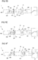
- FIG. 1A to 1F show an example of a checkout system arrangement 1.
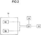
- Fig. 2 shows the connection of some components of the POS system arrangement with one another.
- the cash register system arrangement 1 comprises a goods storage area 16, a goods removal area 17 and a conveyor belt device 10.
- goods W1-W3 that have been deposited in the goods storage area 16 can be transported along a goods feed path P1 into the goods removal area 17.
- the goods removal area 17 in the present case comprises two packing troughs 172, from which goods W1-W3 located therein can be removed and which are separated from each other by a packing tray separation.
- the tray partition comprises an immovable barrier element 170 and a movable barrier element 171 attached thereto.
- the barrier element can be attached to the barrier element in a pivotably articulated manner.
- the packing tray separation can also be realized only by a movable barrier element.
- the conveyor belt device 10 comprises a first belt section 100 and a second belt section 101.
- the second belt section 101 adjoins the first belt section 100.
- Both belt sections 100, 101 can be set in a feed movement and can thus transport goods W1-W3 from the goods deposit area 16 into the goods removal area 17.
- the belt sections 100, 101 form a transition 102 between them. When goods W1-W3 are transported from the first belt section 100 to the second belt section 101, they cross the transition 102 between the belt sections.
- the goods storage area 16 is provided by the first belt section 100.
- the first belt section 100 is formed by a closed, revolving supply belt 105.
- This feed belt 105 is driven by a motor M1 (cf. Fig. 2 ).
- the goods removal area 17 adjoins the second belt section 101.
- the second belt section 101 is arranged between the first belt section 100 and the goods removal area 17.
- the cash register system arrangement 1 further comprises a goods detection device in the form of a portal scanner 13.
- the portal scanner 13 is arranged on the second belt section 101 of the conveyor belt device 10.
- the portal scanner 13 is arranged approximately centrally on the second belt section 101 (or halfway between the first belt section 100 of the conveyor belt device 10 and the goods removal area 17).
- the second belt section 101 is formed by a closed, revolving transport belt 104, by means of which goods W1-W3 can be transported away from the transition 102 and fed to the portal scanner 13.
- the discharge belt 104 is driven by a motor M2.
- the portal scanner 13 is arranged at a distance from the transition 102 between the two belt sections 100, 101.
- the portal scanner 13 comprises one or more means for detecting goods that are transported by the portal scanner 13.
- the portal scanner 13 can comprise a plurality of optical scanning means in order to recognize barcodes or similar markings on the goods W1-W3 and thus to determine the type and number of goods W1-W3.
- the individual prices of the goods W1-W3 and a sum to be paid by the customer can be determined on the basis of the type and number of the goods W1-W3 of a customer.
- the cash register system arrangement 1 comprises a control device 15. This is, as in FIG Fig. 2 shown, connected to the motors M1, M2 of the conveyor belt device 10, to the portal scanner 13 and to the sensor device 14. The connection is made via control lines, for example.
- the motors M1, M2 of the conveyor belt device 10 could also be controlled by a control unit not shown in the figures (for example a programmable logic controller which, if necessary, also controls other functions of the cash register system arrangement, not shown), which in turn is connected to the control device 15 and receives signals from it.
- a control unit not shown in the figures (for example a programmable logic controller which, if necessary, also controls other functions of the cash register system arrangement, not shown), which in turn is connected to the control device 15 and receives signals from it.
- the belt section 100 or belt section 101 can be realized by some other means than a closed, revolving transport belt, such as a roller conveyor or a roller conveyor or roller carpet.
- the control device 15 is only in Figure 1A shown schematically and connected to the conveyor belt device 10, the portal scanner 13 and the sensor device 14 in a suitable manner, for example by electrical control cables, via an RS-232 interface, an RS-485 interface and / or a CAN bus.
- the control device 15 can also be integrated, for example, in the portal scanner 13 or in the sensor device 14, which then also serves as a control device.
- the control device 15 is arranged at a distance from the rest of the cash register system arrangement 1.
- control device 15 is connected to the cash register system arrangement 1 (or its individual components controlled by the control device 15) via suitable means, eg via electrical control cables, via an RS-232 interface, an RS-485 interface and / or a CAN bus.
- suitable means eg via electrical control cables, via an RS-232 interface, an RS-485 interface and / or a CAN bus.
- the goods W1-W3 of the various customers are thereby separated from one another by means of goods dividers 11A, 11B.
- the goods dividers 11A, 11B enable certain goods to be assigned to the various customers.
- goods W1 from a first customer, goods W2 from a second customer and goods W3 from a third customer are shown schematically.
- the goods W1-W3 are separated from one another by two goods dividers 11A, 11B.
- the product dividers 11A, 11B are essentially elongated, in particular rod-shaped.
- the product dividers 11A, 11B are approximately so long that they span a large part of the width of the first and second belt section 100, 101 transversely to the goods feed deposit P1 when they are arranged essentially transversely to the goods feed path P1.
- the goods dividers 11A, 11B are, for example, essentially square, rectangular or triangular in cross section.
- the goods dividers 11A, 11B each include a machine-readable code.
- the machine-readable code can be read out by means of an electromagnetic field, which is e.g. provided by a sensor.
- the machine-readable codes are each provided by an RFID tag 110.
- the RFID tag can be formed by a known 13.56 MHz transponder.
- the already mentioned sensor device 14 is arranged at the end of the first belt section 100 of the conveyor belt device 10.
- the sensor device 14 is provided on the first belt section 100 adjacent to the transition 102 between the first and second belt sections 100, 101 of the conveyor belt device 10.
- the sensor device 14 comprises a detection area 141 (in the Figures 1A to 1F shown in dashed lines).
- the sensor device 14 further comprises a sensor in the form of an RFID antenna 140.
- the RFID antenna 140 is designed to recognize RFID tags 110 of a divider 11A, 11B (or several divider 11A, 11B) and to read out its machine-readable code if the divider 11A, 11B is located in the detection area 141 of the sensor device 14.
- the RFID antenna 140 of the In the present case, the sensor device 14 is arranged under the conveyor belt of the first belt section 100, ie the conveyor belt of the first belt section 100 is located between the goods W1-W3 placed thereon and the RFID antenna 140 of the sensor device 14 arranged below.
- the machine-readable code of the RFID tags 110 includes a UID, by means of which each goods divider 11A, 11B can be uniquely identified. If necessary, individual items of goods can also include an RFID tag.
- the control device 15 comprises a list of UIDs of the goods dividers 11A, 11B and can thus distinguish goods dividers 11A, 11B from goods with RFID tags.
- the portal scanner 13 also includes a sensor in the form of an RFID antenna 130 and an associated detection area 131.
- the design and function of the RFID antenna 130 correspond to the design and function of the RFID antenna 140 of the sensor device 14, so that reference is made to the corresponding description .
- the RFID antenna 130 of the portal scanner 13 is arranged in the area of the portal scanner 13 on the second belt section 101 of the conveyor belt device 10.
- FIG. 1A three customers have placed their goods W1-W3 in the goods storage area 16 one behind the other on the first belt section 100 of the conveyor belt device 10.
- a goods divider 11A was placed by one of the customers.
- the goods divider 11A is aligned essentially perpendicular to the goods feed path P1.
- another goods divider 11B has been placed between the goods W2, W3 of the second and third customers.
- the goods W1-W3 of the individual customers are thus separated from one another by the goods dividers 11A, 11B.
- the control device 15 controls the first belt section 100 of the conveyor belt device 10 in such a way that it executes a feed movement at a first speed V1.
- the control device 15 also controls the second Belt section 101 of the conveyor belt device 10 in such a way that it executes a feed movement at a second speed V2.
- the feed movements take place along the goods feed path P1 in the direction from the goods depositing area 16 to the goods removal area 17.
- the first speed V1 is lower than the second speed V2.
- the first speed V1 can be, for example, approximately two thirds, half or one third of the second speed V2.
- the first speed V1 is in the range from 10 cm / s to 20 cm / s.
- the second speed V2 can be 32 cm / s, for example.
- the cash register system arrangement 1 can comprise a frequency converter. It can be provided that the control unit 15 is designed to apply analog signals to the frequency converter. Specifically, the control unit 15 can be connected to the frequency converter with the following electrical lines: with a first control line, a second control line and a ground line. The control unit 15 can provide an electrical voltage of 0 V or 24 V on the first control line in order to switch a motor on or off. The control unit 15 can provide different voltages on the second control line in order to set a rotational speed of the motor. In particular, a voltage of 5 V can be provided for a low rotational speed when a product divider 11A, 11B is detected by the sensor device 14. Accordingly, a voltage of 10 V can be provided for a higher rotational speed. The speed of a feed movement of a conveyor belt results from the speed of rotation of the motor.
- control device 15 provides signals to a programmable logic controller, which controls the frequency converter as a function of these signals.
- the higher speed of the feed movement of the second belt section 101 compared to the first belt section 100 means that the goods W1-W3 on the second belt section 101 are at a greater distance from one another than on the first belt section 100.
- Figure 1B were the goods W1-W3 opposite Figure 1A already a certain distance along the goods feed path P1 in the direction of the goods removal area 17 transported. Some of the goods W1 of the first customer have already crossed the transition 102 between the first and the second belt section 100, 101 and are conveyed by the second belt section 101. Both goods dividers 11A, 11B are still outside the detection area 141 of the sensor device 14 Figure 1C were the goods W1-W3 opposite Figure 1B transported a certain further distance. All the goods W1 of the first customer have crossed the transition 102 between the first and the second belt section 100, 101 and are conveyed by the second belt section 101.
- the goods separator 11A arranged between the goods W1, W2 of the first and second customer has already been partially transported into the detection area 141 of the sensor device 14 and is now detected by the RFID antenna 140 of the sensor device 14.
- the information captured by the RFID antenna 140 is provided to the control device 15. If the control device 15 detects the UID of a goods separator 11A, 11B, it reduces the speed of the feed movement of the first belt section 100 to a speed V3 which is lower than the speed V1. In one embodiment, this could be reduced, for example, from 20 cm / s to a value for V3 between 10 cm / s and 12 cm / s, in particular 10 cm / s. In addition, it can optionally be provided that the control device 15 also reduces the speed of the feed movement of the first belt section 100 when a large number of goods dividers 11 are detected at short intervals. The evaluation of all tags could otherwise lead to too long a delay.
- Figure 1D were the goods W1-W3 opposite Figure 1C transported over a certain distance.
- the goods separator 11A is still partially in the detection area 141 of the sensor device 14 between the goods W1, W2 of the first and second customers.
- the control device 15 therefore keeps the speed of the feed movement of the first belt section 100 at the speed lower than the speed V1 V3.
- the speed of the feed movement of the second band section 101 is still V2.
- Part of the goods W1 of the first customer has in Figure 1D already crossed the portal scanner 13. The type and number of these goods were recorded by the portal scanner 13 as it passed through.
- the goods divider 11A leaves the detection area 141 of the sensor device 14 between the goods W1, W2 of the first and second customer, as in FIG Figure 1E shown.
- the RFID antenna 140 of the sensor device 14 thus detects the divider 11A no more.
- the control device 15 stops the first belt section 100.
- the control device 15 preferably brings the first belt section 100 to a standstill within 500 ms after the product separator 11A leaves the detection area 141.
- Goods W2 of the second customer following the goods separator 11A remain on the now stationary first belt section 100.
- the goods separator 11A has left the detection area 141 of the sensor device 14 arranged on the first belt section 100 and adjacent to the transition 102 and is therefore already on the second belt section 101.
- the goods W1 of the first customer and the goods separator 11A following these goods W1 are transported to the goods removal area 17 by the second belt section 101, which is still operated at speed V2. In doing so they pass the portal scanner 13.
- the goods divider 11A following the goods W1 of the first customer has in Figure 1F the detection area 131 of the portal scanner 13 has already passed. It was detected by the RFID antenna 130 of the portal scanner 13. The information captured by the RFID antenna 130 of the portal scanner 13 is provided to the control device 15. Thereupon the control device 15 has set the first band section 100 again in a feed movement at the speed V1. Thereupon, the transport of the goods W2 of the second customer begins by the portal scanner 13 in a manner analogous to the transport of the goods W1 of the first customer described above. Before the goods W2 of the second customer reach the goods removal area 17, the control device 15 controls the movable barrier element 171 in such a way that it pivots and releases the other of the two packing trays 172. The first customer thus has enough time to remove his goods W1 from the goods removal area 17.
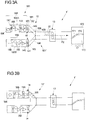
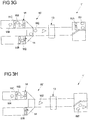
- FIGS 3A-3I show a further embodiment of a cash register system arrangement 1 'with a conveyor belt device 10'. This corresponds in some parts to the exemplary embodiment of the cash register system arrangement 1 according to FIG Figures 1A-1F , wherein like reference numerals indicate corresponding components for their description to the description of the embodiment of the cash register system arrangement 1 according to FIG Figures 1A-1F is referred.
- the POS system arrangement 1 ' accordinging to Figures 3A-3I comprises a first belt section 100 'with a first and a second feed belt 105A, 105B and thus two goods storage areas 16.
- the two feed belts 105A, 105B of the first belt section 100' are arranged essentially parallel to one another and to the discharge belt 104 of the second belt section 101 '.
- the conveyor belt device 10' of the cash register system arrangement 1 ' comprises a connecting section 103 assigned to a second belt section 101'.
- the conveyor belt device 10 ' forms a branched goods feed path P2 which connects the two parallel feed belts 105A, 105B of the first belt section 100' with the second belt section 101 '.
- a transition 102 is formed between each of the two feed belts 105A, 105B of the first belt section 100 'and the connecting section 103.
- Goods W1-W4 which cross one of the transitions 102 can be transported through the connecting section 103 to the removal belt 104.
- the connecting section 103 is formed, for example, by one or more conveyor belts and / or by at least one ramp.
- slopes 106 are arranged on the connecting section 103.
- the bevels 106 each extend between a lateral edge of a feed belt 105A, 105B to a lateral edge of the discharge belt 104.
- the bevels 106 serve to guide the goods W1-W4 to changes in direction of the goods feed path P2.
- the bevels 106 serve to arrange goods W1-W4, which are positioned next to one another on the conveyor belt device 10 '(transversely to the direction of goods advance), one behind the other along the goods advance path P2.
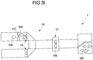
- a sensor device 14 is arranged adjacent to each of the transitions 102 on each of the feed belts 105A, 105B of the first belt section 100 ′.
- the sequence of the feed of goods W1-W4 from four different customers is as follows. First, the control device 15 displaces one of the two feed belts 105A, 105B of the first belt section 100 'in a feed movement (at the first speed V1). In the present example, the first feed belt 105A illustrated above is first set in a feed movement. As a result, the goods W1 of the first customer are transported via the connecting section 103 to the removal belt 104 of the second belt section 101 ', cf. Figures 3A-3D .
- the control device 15 slows down the feed speed of the first tape section.
- the control device 15 stops the first feed belt 105A of the first belt section 100 ', cf. Figure 3E .
- the control device 15 sets the second feed belt 105B of the first belt section 100 'into a feed movement ( with speed V1), cf. Figure 3F .
- the second customer's goods W2 are then transported by the portal scanner 13. So that the goods W1, W2 of the first and second customer do not mix in the goods removal area 17, the control device 15 controls the movable barrier element 171 so that it swivels and closes the packing tray 172 into which the goods W1 of the first customer were transported. This takes place before the goods W2 of the second customer arrive at the goods removal area 17, cf. Figure 3G . The goods W2 of the second customer are thereby transported by the movable barrier element 171 into the second packing tray 172.
- the control device 15 reduces the speed of the second feed belt 105B, cf. Figure 3H .
- control device 15 stops the second feed belt 105B, cf. Figure 3I .
- the procedure for transporting the goods W3 of the third customer is then analogous to the transport of the goods W1 of the first customer.
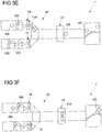
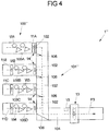
- FIG. 4 shows a further exemplary embodiment of a checkout system arrangement 1 ′′. This corresponds in some parts to the exemplary embodiments of the checkout system arrangement 1; 1 ′ according to FIG Figures 1A-1F and Figures 3A-3I , wherein like reference numerals indicate corresponding components, with respect to which reference is made to the preceding description.
- the POS system arrangement 1 "of the Fig. 4 comprises a branched goods feed path P3, which in the present case connects four feed belts 105A-105D of a first belt section 100 "with a second belt section 101".
- the second belt section comprises a connecting section 103 ′, which forms a transition 102 with each of the feed belts 105A-105D of the first belt section 100 ′′.
- a plurality of bevels 106 are provided on the connecting section 103 '.
- a bevel 106 is arranged adjacent to each of the transitions 102.
- an incline 106 extends from a corner at which each of the transitions 102 meets an edge (lateral along the feed direction) of the respective first feed belts 105A-105D of the first belt section 100 ′′.
- the inclines 106 are also located there arranged where the goods feed path P3 performs a change in direction.
- the connecting section 103 ' is designed as a conveyor belt.
- the infeed belts 105A-105D of the first belt section 100 ′′ are aligned essentially parallel to the outfeed belt 104 and perpendicular to the connecting section 103 '. Otherwise, the infeed belts 105A-105D essentially correspond to the infeed belts 105; 105A, 105B of the exemplary embodiments of the cash register system arrangements 1; 1' according to the Figures 1A-1F ; 3A-3I . Reference is also made to the description there with regard to the design and functioning of the portal scanner 13, the sensor devices 14 and the control device 15.
- a particularly large number of customers can display their goods W1-W4 at the same time.
- the goods W1-W4 are transported to the portal scanner 13 one after the other. This can be used particularly efficiently.
- Several goods dividers 11A-11D separate goods W1-W4 of the customers on the infeed belts 105A-105D from goods of preceding or following customers.
- a goods removal area 17 (not shown here) can optionally be connected to the cash register system arrangement 1 ′′.
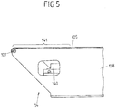
- Fig. 5 shows a side view of the end region of the feed belt 105 of the first belt section 100; 100 '; 100 ", which in the exemplary embodiments of the cash register system arrangements 1; 1 ';1" described above is attached to the respective second belt section 101; 101 '; 101 ′′ (and thus each forms a transition 102).
- the feed belt 105 is deflected on a deflection roller 107.
- the deflection roller 107 is articulated on a frame 108.
- the frame 108 is made of a metal, for example aluminum or sheet steel produced.
- the RFID antenna 140 of the sensor device 14 is arranged below the feed belt 105. It is also arranged at a distance from the feed belt 105. The distance is between 1.5 cm and 10 cm. At such a distance, an RFID tag 110 of a goods divider 11A-11D can be recognized up to approximately 2.5 cm above the infeed belt 105.
- the RFID antenna 141 is provided so that it can be adjusted in height (so that the distance from the feed belt 105 can be adjusted). This ensures that the RFID tags are recorded as precisely as possible.
- the RFID antenna 140 extends essentially over the entire width of the feed belt 105. In this case, however, the RFID antenna 140 can be somewhat narrower than the feed belt 105 (for example about 2 cm). There is preferably a distance of approximately 1 cm on both sides between the RFID antenna 140 and the frame 108. As a result, goods dividers 11A-11D can be fed back laterally on the infeed belt 105 without being detected by the RFID antenna. Thus, when a merchandise divider is returned (as is customary in cash register systems), there is no disruption of the cash register system arrangement 1; 1';1".
- the detection area 141 of the sensor arrangement 14 extends (when used as intended) above the RFID antenna 140.
- a plastic window e.g. made of Plexiglas, polycarbonate, composite material HPL, etc. is not shown here .ä.) arranged between the RFID antenna and the feed belt 105.
- the RFID antenna 141 is shielded against interference from other components of the POS system arrangement (e.g. a conveyor belt motor) by means of suitable shielding, e.g. by using shielded and / or cable connections provided with ferrite cores.
- Fig. 6 shows a flowchart according to which each feed belt of the cash register system arrangements 1, 1 ′, 1 ′′ described above can be controlled by means of the control device 15.
- step S1 the control device 15 is activated (step S1). If the controlled POS system arrangement comprises more than one infeed belt, only one of the infeed belts is active at the same time in order to transport goods to the outfeed belt.
- step S2 it is checked whether the status of the feed belt to be controlled is currently "active". If this is not the case, the speed of the feed belt is set to zero in step S3 (or kept at zero), whereupon the process continues again in step S2. The feed belt is therefore stopped or left at a standstill. If, on the other hand, the status of the feed belt is "active", a transport process begins (beginning with step S4).
- the status of the infeed belt is set to "active", e.g. manually via the control device 15 (e.g. a PLC), for example by inputting an operator.
- setting the status of the feed belt to "active” consists in setting a corresponding status indicator ("flag") of the control device 15.
- the flag is set to "active” automatically when an event occurs, for example when an event occurs (for example by means of a proximity sensor) detected approach of a customer to the POS system arrangement. The flag is only set when a purchase process is to begin.
- step S4 it is checked whether the sensor device 14 is currently detecting a divider 11A-11D.
- step S4 If a goods divider 11A-11D is currently detected by the sensor device 14 in step S4, the process continues with step S5.
- step S8 If no goods separator 11A-11D is currently detected by the sensor device 14 in step S4, then the process continues with step S8. There, by querying a memory provided for this purpose, it is checked whether the sensor device 14 has already detected a goods divider 11A-11D in the current transport process. If it has not yet detected a goods divider 11A-11D in the current transport process, the speed of the feed belt is set to V1 in step S9 and the process continues with step S4.
- the speed V1 is e.g. between 20 cm / s and 22 cm / s.
- step S8 If it is recognized in step S8 by querying the memory that a goods divider 11A-11D has already been detected by the sensor device 14 at least once in the current transport process, the control device 15 pauses in step S10, e.g. for 500 ms or for up to 500 ms. The process then continues with step S11.
- step S11 If a goods divider is detected again by the sensor device 14 in step S11, the process continues with step S5. In this way, short interruptions in the detection of the divider 11A-11D are taken into account.
- step S11 If no goods separator 11A-11D is detected by the sensor device 14 in step S11, the control device 15 sets the speed of the feed belt to zero (or keeps it at zero) and goes to step S2. In step S5, the feed belt is set at a speed V3. The speed V3 is e.g. between 10 cm / s and 12 cm / s. The process then continues with step S6. In step S6 it is checked by querying the memory whether the sensor device 14 has already detected a goods divider 11A-11D in the current transport process. If the goods divider 11A-11D has not yet been detected, the information is stored in the memory in step S7 that a goods separator 11A-11D has now been detected. The procedure then continues again with step S4.
- a checkout system arrangement can also have a number of conveyor belts of the first belt sections (not shown here), for example three, five or six.
- the conveyor belts of the first belt sections of the cash register system arrangements are arranged parallel to one another.
- the goods can include RFID tags and can be detected by means of the RFID antenna of the goods detection device.
- a classic, staff-operated registration station can also be used as the goods registration device.
- the sensor (the RFID antenna) of the sensor device does not necessarily have to be arranged below the conveyor belt, but can alternatively generally also be arranged above the conveyor belt.
- machine-readable codes can also be attached to goods dividers, which are then read out by a corresponding other type of sensor.
- the machine-readable code can be used as a barcode, QR code or other detectable (e.g. visible) marker (e.g. in the form of a graphic, a clear pattern or image) or in the form of a digital watermark (especially imperceptible to the human eye) (e.g. from DigiMarc, Portland, USA).
- An optical detection unit then serves as the sensor.
- the RFID antenna can be arranged within a ferrite cage or housing that is open on one side.
- the open side of the ferrite cage or housing points towards the detection area. If the RFID antenna is arranged below the feed belt, the open side can, for example, point upwards.
- the ferrite housing can in particular be designed in the form of a cuboid made of ferrite plates. The size of the opening of the ferrite cage or housing can be adjustable.
- the size of the detection area can depend, for example, on the specific properties of the RFID antenna. Furthermore, the size of the detection area can be adjusted, for example by adjusting the size of the opening of a ferrite cage or housing and / or by arranging a window or a boundary made of metal, in particular metal plates, between the RFID antenna and the feed belt.
Landscapes
- Physics & Mathematics (AREA)
- General Physics & Mathematics (AREA)
- Engineering & Computer Science (AREA)
- Theoretical Computer Science (AREA)
- Computer Security & Cryptography (AREA)
- Microelectronics & Electronic Packaging (AREA)
- Computer Hardware Design (AREA)
- Health & Medical Sciences (AREA)
- Electromagnetism (AREA)
- General Health & Medical Sciences (AREA)
- Toxicology (AREA)
- Artificial Intelligence (AREA)
- Computer Vision & Pattern Recognition (AREA)
- Control Of Conveyors (AREA)
- Cash Registers Or Receiving Machines (AREA)
Claims (8)
- Arrangement de système de caisse, comprenant :- un équipement de bande transporteuse (10 ; 10' ; 10") comprenant au moins une portion de bande (100, 101 ; 100', 101' ; 100", 101"), laquelle peut être mise dans un mouvement d'avance en vue de transporter des marchandises (W1-W4) qui se trouvent sur celle-ci le long d'un chemin d'avance de marchandises (P1-P3), les marchandises (W1-W4) pouvant être séparées les unes des autres le long du chemin d'avance de marchandises (P1-P3) par au moins un séparateur de marchandises (11A-11D), et- un dispositif de détection de marchandises (13) destiné à détecter des marchandises (W1-W4) transportées au moyen de l'équipement de bande transporteuse (10 ; 10'; 10"),- plusieurs dispositifs capteurs (14) espacés du dispositif de détection de marchandises (13) le long du chemin d'avance de marchandises (P1-P3) comprenant chacun un capteur (140) et une zone de détection (141), les dispositifs capteurs (14) étant respectivement configurés pour détecter, au moyen du capteur (140), si le séparateur de marchandises (11A-11D) se trouve dans la zone de détection (141), et- un dispositif de commande (15), qui est configuré pour commander le mouvement d'avance de la portion de bande (100, 101; 100', 101' ; 100", 101") de l'équipement de bande transporteuse (10 ; 10' ; 10") en fonction de la détection du séparateur de marchandises (11A-11D) dans la zone de détection (141) des dispositifs capteurs (14),- l'équipement de transport possédant au moins une première portion de bande (100 ; 100' ; 100"), qui est configurée pour déposer des marchandises (W1-W4), et une deuxième portion de bande (101 ; 101'; 101"), la première portion de bande (100 ; 100' ; 100") étant adjacente à la deuxième portion de bande (101 ; 101' ; 101") au niveau de plusieurs transitions (102),- et le dispositif de commande (15) étant configuré pour mettre la première portion de bande (100 ; 100' ; 100") dans un mouvement d'avance à une première vitesse et la deuxième portion de bande (101 ; 101' ; 101") dans un mouvement d'avance à une deuxième vitesse,caractérisé en ce que- la première portion de bande (100 ; 100' ; 100") comporte plusieurs bandes d'amenée (105A-105D), lesquelles sont reliées à la deuxième portion de bande (101 ; 101' ; 101") de telle sorte que des marchandises peuvent être transportées des bandes d'amenée (105A-105D) sur la deuxième portion de bande (101 ; 101' ; 101") et continuer d'être transportées par celle-ci,- la deuxième portion de bande (101 ; 101' ; 101") est configurée pour transporter les marchandises (W1-W4) déposées sur la première portion de bande (100 ; 100' ; 100") dans la zone de détection (130) du dispositif de détection de marchandises (13),- les bandes d'amenée (105A-105D) sont reliées par le biais d'une portion de liaison (103, 103') de la deuxième portion de bande (101 ; 101' ; 101") réalisée sous la forme d'une bande transporteuse, une transition (102) étant formée entre chacune des bandes d'amenée (105A-105D) et la portion de liaison (103, 103'),- l'un des dispositifs capteurs (14) est disposé voisin de chaque transition (102), la zone de détection (141) des dispositifs capteurs (14) étant disposée au niveau de la transition (102) respective,- le dispositif de commande (15) est configuré pour commander les vitesses de la première et de la deuxième portion de bande (100 ; 100' ; 100" ; 101 ; 101' ; 101") en fonction de la détection du séparateur de marchandises (11A-11D) dans la zone de détection du dispositif capteur (14) ;- les dispositifs capteurs (14) sont respectivement configurés pour détecter, au moyen du capteur (140), en lisant un code lisible par machine présent sur un séparateur de marchandises (11A-11D) qui se trouve sur la bande d'amenée (105A-105D) qui est associée au dispositif capteur (14), si le séparateur de marchandises (11A-11D) se trouve dans la zone de détection (141), et- le dispositif de commande (15) est configuré pour- réduire une vitesse du mouvement d'avance de la bande d'amenée (105A-105D) pendant que le séparateur de marchandises (11A-11D) se trouve dans la zone de détection (141) du dispositif capteur (14) ; et- arrêter la bande d'amenée (105A-105D) dès que le séparateur de marchandises (11A-11D) quitte la zone de détection (141) du dispositif capteur (14).
- Arrangement de système de caisse selon la revendication 1, caractérisé en ce que le dispositif de détection de marchandises (13) est réalisé sous la forme d'un lecteur à balayage à portique.
- Arrangement de système de caisse selon l'une des revendications précédentes, caractérisé en ce que le code lisible par machine présent sur le séparateur de marchandises (11A-11D) est lu à l'aide d'un champ électromagnétique généré par le capteur (140) du dispositif capteur (14).
- Arrangement de système de caisse selon l'une des revendications précédentes, caractérisé en ce que le code lisible par machine présent sur le séparateur de marchandises (11A-11D) est fourni par une étiquette RFID (110) et en ce que le capteur (140) du dispositif capteur (14) est réalisé sous la forme d'une antenne RFID destinée à lire l'étiquette RFID (110) du séparateur de marchandises (11A-11D).
- Arrangement de système de caisse selon l'une des revendications précédentes, caractérisé en ce que le code lisible par machine présent sur le séparateur de marchandises (11A-11D) est réalisé sous la forme d'un code à barres, d'un code QR, d'un graphique, d'un motif et/ou d'un filigrane numérique.
- Arrangement de système de caisse selon l'une des revendications précédentes, caractérisé par plusieurs séparateurs de marchandises (11A-11D), les séparateurs de marchandises (11A-11D) pouvant être identifiés univoquement à l'aide du code lisible par machine présent sur les séparateurs de marchandises (11A-11D).
- Arrangement de système de caisse selon l'une des revendications précédentes, caractérisé en ce que la deuxième vitesse est supérieure à la première vitesse.
- Procédé pour faire fonctionner un arrangement de système de caisse, qui comporte- un équipement de bande transporteuse (10 ; 10' ; 10") comprenant au moins une portion de bande (100, 101 ; 100', 101' ; 100", 101"), laquelle peut être mise dans un mouvement d'avance en vue de transporter des marchandises (W1-W4) qui se trouvent sur celle-ci le long d'un chemin d'avance de marchandises (P1-P3), les marchandises (W1-W4) pouvant être séparées les unes des autres le long du chemin d'avance de marchandises (P1-P3) par au moins un séparateur de marchandises (11A-11D), et- un dispositif de détection de marchandises (13) destiné à détecter des marchandises (W1-W4) transportées au moyen de l'équipement de bande transporteuse (10 ; 10'; 10"),- plusieurs dispositifs capteurs (14) espacés du dispositif de détection de marchandises (13) le long du chemin d'avance de marchandises (P1-P3) comprenant chacun un capteur (140) et une zone de détection (141), et- un dispositif de commande (15),les dispositifs capteurs (14) détectant respectivement, au moyen du capteur (140), si le séparateur de marchandises (11A-11D) se trouve dans la zone de détection (141) et le dispositif de commande (15) commandant le mouvement d'avance de la portion de bande (100, 101 ; 100', 101' ; 100", 101") de l'équipement de bande transporteuse (10 ; 10' ; 10") en fonction de la détection du séparateur de marchandises (11A-11D) dans la zone de détection (141) des dispositifs capteurs (14), l'équipement de transport possédant au moins une première portion de bande (100 ; 100' ; 100"), qui est configurée pour déposer des marchandises (W1-W4), et une deuxième portion de bande (101 ; 101' ; 101"), qui est configurée pour transporter les marchandises (W1-W4) déposées sur la première portion de bande (100 ; 100' ; 100") dans la zone de détection (130) du dispositif de détection de marchandises (13), la première portion de bande (100 ; 100' ; 100") étant adjacente à la deuxième portion de bande (101 ; 101' ; 101") au niveau d'une transition (102),
et le dispositif de commande (15) mettant la première portion de bande (100 ; 100' ; 100") dans un mouvement d'avance à une première vitesse et la deuxième portion de bande (101 ; 101' ; 101") dans un mouvement d'avance à une deuxième vitesse,
caractérisé en ce que- la première portion de bande (100 ; 100' ; 100") comporte plusieurs bandes d'amenée (105A-105D), lesquelles sont reliées à la deuxième portion de bande (101 ; 101' ; 101") de telle sorte que des marchandises peuvent être transportées des bandes d'amenée (105A-105D) sur la deuxième portion de bande (101 ; 101' ; 101") et continuer d'être transportées par celle-ci,- la deuxième portion de bande (101 ; 101' ; 101") est configurée pour transporter les marchandises (W1-W4) déposées sur la première portion de bande (100 ; 100' ; 100") dans la zone de détection (130) du dispositif de détection de marchandises (13),- les bandes d'amenée (105A-105D) sont reliées par le biais d'une portion de liaison (103, 103') de la deuxième portion de bande (101 ; 101' ; 101") réalisée sous la forme d'une bande transporteuse, une transition (102) étant formée entre chacune des bandes d'amenée (105A-105D) et la portion de liaison (103, 103'),- l'un des dispositifs capteurs (14) est disposé voisin de chaque transition (102), la zone de détection (141) du dispositif capteur (14) étant disposée au niveau de la transition (102) respective,- la commande des vitesses de la première et de la deuxième portion de bande (100 ; 100' ; 100"; 101 ; 101' ; 101'') s'effectue en fonction de la détection du séparateur de marchandises (11A-11D) dans la zone de détection du dispositif capteur (14) ;- lecture, par le dispositif capteur (14) au moyen du capteur (140), d'un code lisible par machine présent sur un séparateur de marchandises (11A-11D) qui se trouve sur la bande d'amenée (105A-105D) qui est associée au dispositif capteur (14), afin de détecter si le séparateur de marchandises (11A-11D) se trouve dans la zone de détection (141) ;- réduction d'une vitesse du mouvement d'avance de la bande d'amenée (105A-105D) pendant que le séparateur de marchandises (11A-11D) se trouve dans la zone de détection (141) du dispositif capteur (14) ; et- arrêt de la bande d'amenée (105A-105D) dès que le séparateur de marchandises (11A-11D) quitte la zone de détection (141) du dispositif capteur (14).
Priority Applications (2)
| Application Number | Priority Date | Filing Date | Title |
|---|---|---|---|
| EP15165711.1A EP3087877B1 (fr) | 2015-04-29 | 2015-04-29 | Agencement de système de caisses doté d'une détection de barre de séparation pour marchandise |
| US15/141,737 US9965927B2 (en) | 2015-04-29 | 2016-04-28 | Checkout system assembly with goods separator detection |
Applications Claiming Priority (1)
| Application Number | Priority Date | Filing Date | Title |
|---|---|---|---|
| EP15165711.1A EP3087877B1 (fr) | 2015-04-29 | 2015-04-29 | Agencement de système de caisses doté d'une détection de barre de séparation pour marchandise |
Publications (2)
| Publication Number | Publication Date |
|---|---|
| EP3087877A1 EP3087877A1 (fr) | 2016-11-02 |
| EP3087877B1 true EP3087877B1 (fr) | 2021-06-02 |
Family
ID=53180529
Family Applications (1)
| Application Number | Title | Priority Date | Filing Date |
|---|---|---|---|
| EP15165711.1A Active EP3087877B1 (fr) | 2015-04-29 | 2015-04-29 | Agencement de système de caisses doté d'une détection de barre de séparation pour marchandise |
Country Status (2)
| Country | Link |
|---|---|
| US (1) | US9965927B2 (fr) |
| EP (1) | EP3087877B1 (fr) |
Families Citing this family (8)
| Publication number | Priority date | Publication date | Assignee | Title |
|---|---|---|---|---|
| US10028599B2 (en) | 2016-01-21 | 2018-07-24 | Walmart Apollo, Llc | High velocity checkout terminal |
| FR3062996B1 (fr) * | 2017-02-23 | 2021-06-04 | Hmy Group | Station d'encaissement d'articles de marchandise configuree pour equiper un magasin de vente au detail |
| US10106327B2 (en) | 2017-06-20 | 2018-10-23 | Walmart Apollo, Llc | Checkout station bumper |
| JP7379111B2 (ja) * | 2019-11-21 | 2023-11-14 | 東芝テック株式会社 | 無線タグ読取装置、及び無線タグ情報処理システム |
| DE202020103986U1 (de) * | 2020-07-09 | 2020-07-22 | KEMAS Gesellschaft für Elektronik, Elektromechanik, Mechanik und Systeme mbH | Erfassungsvorrichtung |
| IT202000024193A1 (it) | 2020-10-14 | 2022-04-14 | Imola Retail Solutions S R L | Banco cassa con sistema di sensori che avvertono la presenza di un cliente |
| US11935031B2 (en) * | 2020-12-15 | 2024-03-19 | Visa International Service Association | Two-dimensional code compatibility system |
| CN113772312B (zh) * | 2021-09-14 | 2023-10-13 | 深圳市库宝软件有限公司 | 货物运输控制方法、装置、设备、仓储系统及存储介质 |
Citations (3)
| Publication number | Priority date | Publication date | Assignee | Title |
|---|---|---|---|---|
| EP2472432A1 (fr) * | 2011-01-04 | 2012-07-04 | Wincor Nixdorf International GmbH | Dispositif de détection de marchandises, agencement et procédé de fonctionnement |
| WO2014014954A1 (fr) * | 2012-07-16 | 2014-01-23 | Brackenridge Stephanie L | Procédés et système de traitement de clients par l'intermédiaire d'un système de point de vente ayant un appareil pour scanner le prix de plusieurs articles |
| WO2015053688A1 (fr) * | 2013-10-09 | 2015-04-16 | Itab Scanflow Ab | Systeme de tapis roulant pour caisse de sortie |
Family Cites Families (11)
| Publication number | Priority date | Publication date | Assignee | Title |
|---|---|---|---|---|
| CH526290A (de) | 1970-07-02 | 1972-08-15 | Zellweger Uster Ag | Markierkörper und Verwendung desselben |
| DE69224777T2 (de) | 1991-07-19 | 1998-07-09 | Kabushiki Kaisha Tec, Shizuoka | Warenabrechnungsanlage |
| GB2381368A (en) | 2001-10-29 | 2003-04-30 | Bay Media Ltd | Point of sale seperator bar |
| US7337960B2 (en) * | 2004-02-27 | 2008-03-04 | Evolution Robotics, Inc. | Systems and methods for merchandise automatic checkout |
| DE102008010642B4 (de) | 2008-02-22 | 2023-12-21 | Diebold Nixdorf Systems Gmbh | Warentrennstab mit maschinenlesbarer Markierung |
| DE202008003738U1 (de) | 2008-07-08 | 2008-10-16 | Korqaj, Mehmedali | Warentrenner |
| WO2012103155A2 (fr) | 2011-01-24 | 2012-08-02 | Datalogic ADC, Inc. | Systèmes et procédés destinés à fournir un retour à un utilisateur travaillant à une caisse automatisée |
| US20120187195A1 (en) | 2011-01-24 | 2012-07-26 | Datalogic ADC, Inc. | Systems and methods for reading encoded data through gaps between conveyors in an automated checkout system |
| CN103339640B (zh) * | 2011-01-24 | 2017-06-13 | 数据逻辑Adc公司 | 捕获自动数据读取器中的安全图像的系统和方法 |
| US8960549B2 (en) * | 2012-06-29 | 2015-02-24 | Ncr Corporation | Method, apparatus and system for scanning an optical code |
| US20140129362A1 (en) * | 2012-11-05 | 2014-05-08 | Craig Lewis Marquis | Systems and methods for resolving exceptions during a retail checkout |
-
2015
- 2015-04-29 EP EP15165711.1A patent/EP3087877B1/fr active Active
-
2016
- 2016-04-28 US US15/141,737 patent/US9965927B2/en active Active
Patent Citations (3)
| Publication number | Priority date | Publication date | Assignee | Title |
|---|---|---|---|---|
| EP2472432A1 (fr) * | 2011-01-04 | 2012-07-04 | Wincor Nixdorf International GmbH | Dispositif de détection de marchandises, agencement et procédé de fonctionnement |
| WO2014014954A1 (fr) * | 2012-07-16 | 2014-01-23 | Brackenridge Stephanie L | Procédés et système de traitement de clients par l'intermédiaire d'un système de point de vente ayant un appareil pour scanner le prix de plusieurs articles |
| WO2015053688A1 (fr) * | 2013-10-09 | 2015-04-16 | Itab Scanflow Ab | Systeme de tapis roulant pour caisse de sortie |
Also Published As
| Publication number | Publication date |
|---|---|
| EP3087877A1 (fr) | 2016-11-02 |
| US20160321877A1 (en) | 2016-11-03 |
| US9965927B2 (en) | 2018-05-08 |
Similar Documents
| Publication | Publication Date | Title |
|---|---|---|
| EP3087877B1 (fr) | Agencement de système de caisses doté d'une détection de barre de séparation pour marchandise | |
| DE3883681T2 (de) | Verfahren und Anordnung zum Vereinzeln von Gegenständen auf einem Fördersystem. | |
| EP2789555B1 (fr) | Procédé de préparation de marchandises individuelles pour plusieurs commandes à partir d'un entrepôt de marchandises | |
| DE69806144T2 (de) | Intelligente hochgeschwindigkeits-ablenkvorrichtung für sortierförderer | |
| DE102015117241B4 (de) | Ansteuerung einer Förderanlage | |
| EP3501995B1 (fr) | Procédé de commande des paramètres d'un système de banderolage | |
| EP2892835B1 (fr) | Dispositif et procédé de commande du guidage précis d'une pile de documents de valeur | |
| EP2456696B1 (fr) | Procédé permettant de charger des unités de chargement sur un support de chargement | |
| DE102010005267A1 (de) | Fördereinrichtung für Stückgut, Aufsatzvorrichtung für eine Fördereinrichtung, Stückgutverteilanlage und Verfahren zum Einbringen von Stückgut in eine Stückgutverteilanlage | |
| EP3437745B1 (fr) | Trieur matriciel | |
| AT501826A1 (de) | Vorrichtung zum fördern und vereinzeln von ferromagnetischen teilen | |
| EP2620775B1 (fr) | Cartouche d'enregistrement | |
| DE102011000819B4 (de) | Ladesystem für ein Flugzeug und Verfahren zur Förderung eines Frachtstücks auf einem Frachtdeck | |
| WO2009103410A1 (fr) | Barre séparatrice de marchandises dotée d'un marquage lisible par machine | |
| DE102011003027A1 (de) | System und Verfahren zur Lagerung und Überwachung von Gütern mittels RFID-Technologie | |
| EP2719642A1 (fr) | Dispositif et procédé destinés à la séparation de marchandises | |
| DE202006020496U1 (de) | Sensorvorrichtung zum Erkennen elektromagnetisch detektierbarer Fördergutteile und Sortiervorrichtung mit einer solchen Sensorvorrichtung | |
| EP2070845B1 (fr) | Méthode et dipsositif pour regrouper les cintres | |
| DE29800833U1 (de) | Vorrichtung zur Identifikation eines Objekts auf einem Förderband | |
| DE3037166C2 (de) | Verfahren zum Schneiden von Kartonzuschnitten sowie Steuerschaltung zur Durchführung des Verfahrens | |
| EP2844442B1 (fr) | Machine pour la fabrication a partir de matériaux en forme de bande ou feuille | |
| DE3136340A1 (de) | Verfahren und vorrichtung zum ordnen von werkstuecken | |
| DE102018218021B4 (de) | Verfahren zum räumlichen Anordnen von Coils in einem Coillager sowie Kombination aus einer Verarbeitungsmaschine und einem Coillager | |
| DE3411902A1 (de) | Verfahren zum abstapeln von ferromagnetischen blechplatinen sowie vorrichtung zur durchfuehrung des verfahrens | |
| EP2479720B1 (fr) | Système et procédé de stockage et de surveillance de marchandises à l'aide de la technologie RFID |
Legal Events
| Date | Code | Title | Description |
|---|---|---|---|
| PUAI | Public reference made under article 153(3) epc to a published international application that has entered the european phase |
Free format text: ORIGINAL CODE: 0009012 |
|
| AK | Designated contracting states |
Kind code of ref document: A1 Designated state(s): AL AT BE BG CH CY CZ DE DK EE ES FI FR GB GR HR HU IE IS IT LI LT LU LV MC MK MT NL NO PL PT RO RS SE SI SK SM TR |
|
| AX | Request for extension of the european patent |
Extension state: BA ME |
|
| 17P | Request for examination filed |
Effective date: 20170427 |
|
| RBV | Designated contracting states (corrected) |
Designated state(s): AL AT BE BG CH CY CZ DE DK EE ES FI FR GB GR HR HU IE IS IT LI LT LU LV MC MK MT NL NO PL PT RO RS SE SI SK SM TR |
|
| STAA | Information on the status of an ep patent application or granted ep patent |
Free format text: STATUS: REQUEST FOR EXAMINATION WAS MADE |
|
| STAA | Information on the status of an ep patent application or granted ep patent |
Free format text: STATUS: EXAMINATION IS IN PROGRESS |
|
| 17Q | First examination report despatched |
Effective date: 20180416 |
|
| GRAP | Despatch of communication of intention to grant a patent |
Free format text: ORIGINAL CODE: EPIDOSNIGR1 |
|
| STAA | Information on the status of an ep patent application or granted ep patent |
Free format text: STATUS: GRANT OF PATENT IS INTENDED |
|
| RIC1 | Information provided on ipc code assigned before grant |
Ipc: G07D 7/00 20160101ALI20201029BHEP Ipc: G07G 1/00 20060101ALI20201029BHEP Ipc: A47F 9/04 20060101AFI20201029BHEP |
|
| INTG | Intention to grant announced |
Effective date: 20201125 |
|
| GRAS | Grant fee paid |
Free format text: ORIGINAL CODE: EPIDOSNIGR3 |
|
| GRAA | (expected) grant |
Free format text: ORIGINAL CODE: 0009210 |
|
| STAA | Information on the status of an ep patent application or granted ep patent |
Free format text: STATUS: THE PATENT HAS BEEN GRANTED |
|
| REG | Reference to a national code |
Ref country code: CH Ref legal event code: EP |
|
| AK | Designated contracting states |
Kind code of ref document: B1 Designated state(s): AL AT BE BG CH CY CZ DE DK EE ES FI FR GB GR HR HU IE IS IT LI LT LU LV MC MK MT NL NO PL PT RO RS SE SI SK SM TR |
|
| REG | Reference to a national code |
Ref country code: GB Ref legal event code: FG4D Free format text: NOT ENGLISH |
|
| REG | Reference to a national code |
Ref country code: AT Ref legal event code: REF Ref document number: 1397644 Country of ref document: AT Kind code of ref document: T Effective date: 20210615 |
|
| REG | Reference to a national code |
Ref country code: IE Ref legal event code: FG4D Free format text: LANGUAGE OF EP DOCUMENT: GERMAN |
|
| REG | Reference to a national code |
Ref country code: DE Ref legal event code: R096 Ref document number: 502015014762 Country of ref document: DE |
|
| REG | Reference to a national code |
Ref country code: LT Ref legal event code: MG9D |
|
| PG25 | Lapsed in a contracting state [announced via postgrant information from national office to epo] |
Ref country code: HR Free format text: LAPSE BECAUSE OF FAILURE TO SUBMIT A TRANSLATION OF THE DESCRIPTION OR TO PAY THE FEE WITHIN THE PRESCRIBED TIME-LIMIT Effective date: 20210602 Ref country code: LT Free format text: LAPSE BECAUSE OF FAILURE TO SUBMIT A TRANSLATION OF THE DESCRIPTION OR TO PAY THE FEE WITHIN THE PRESCRIBED TIME-LIMIT Effective date: 20210602 Ref country code: FI Free format text: LAPSE BECAUSE OF FAILURE TO SUBMIT A TRANSLATION OF THE DESCRIPTION OR TO PAY THE FEE WITHIN THE PRESCRIBED TIME-LIMIT Effective date: 20210602 Ref country code: BG Free format text: LAPSE BECAUSE OF FAILURE TO SUBMIT A TRANSLATION OF THE DESCRIPTION OR TO PAY THE FEE WITHIN THE PRESCRIBED TIME-LIMIT Effective date: 20210902 |
|
| REG | Reference to a national code |
Ref country code: NL Ref legal event code: MP Effective date: 20210602 |
|
| PG25 | Lapsed in a contracting state [announced via postgrant information from national office to epo] |
Ref country code: GR Free format text: LAPSE BECAUSE OF FAILURE TO SUBMIT A TRANSLATION OF THE DESCRIPTION OR TO PAY THE FEE WITHIN THE PRESCRIBED TIME-LIMIT Effective date: 20210903 Ref country code: LV Free format text: LAPSE BECAUSE OF FAILURE TO SUBMIT A TRANSLATION OF THE DESCRIPTION OR TO PAY THE FEE WITHIN THE PRESCRIBED TIME-LIMIT Effective date: 20210602 Ref country code: RS Free format text: LAPSE BECAUSE OF FAILURE TO SUBMIT A TRANSLATION OF THE DESCRIPTION OR TO PAY THE FEE WITHIN THE PRESCRIBED TIME-LIMIT Effective date: 20210602 Ref country code: SE Free format text: LAPSE BECAUSE OF FAILURE TO SUBMIT A TRANSLATION OF THE DESCRIPTION OR TO PAY THE FEE WITHIN THE PRESCRIBED TIME-LIMIT Effective date: 20210602 Ref country code: PL Free format text: LAPSE BECAUSE OF FAILURE TO SUBMIT A TRANSLATION OF THE DESCRIPTION OR TO PAY THE FEE WITHIN THE PRESCRIBED TIME-LIMIT Effective date: 20210602 Ref country code: NO Free format text: LAPSE BECAUSE OF FAILURE TO SUBMIT A TRANSLATION OF THE DESCRIPTION OR TO PAY THE FEE WITHIN THE PRESCRIBED TIME-LIMIT Effective date: 20210902 |
|
| PG25 | Lapsed in a contracting state [announced via postgrant information from national office to epo] |
Ref country code: EE Free format text: LAPSE BECAUSE OF FAILURE TO SUBMIT A TRANSLATION OF THE DESCRIPTION OR TO PAY THE FEE WITHIN THE PRESCRIBED TIME-LIMIT Effective date: 20210602 Ref country code: CZ Free format text: LAPSE BECAUSE OF FAILURE TO SUBMIT A TRANSLATION OF THE DESCRIPTION OR TO PAY THE FEE WITHIN THE PRESCRIBED TIME-LIMIT Effective date: 20210602 Ref country code: SM Free format text: LAPSE BECAUSE OF FAILURE TO SUBMIT A TRANSLATION OF THE DESCRIPTION OR TO PAY THE FEE WITHIN THE PRESCRIBED TIME-LIMIT Effective date: 20210602 Ref country code: SK Free format text: LAPSE BECAUSE OF FAILURE TO SUBMIT A TRANSLATION OF THE DESCRIPTION OR TO PAY THE FEE WITHIN THE PRESCRIBED TIME-LIMIT Effective date: 20210602 Ref country code: RO Free format text: LAPSE BECAUSE OF FAILURE TO SUBMIT A TRANSLATION OF THE DESCRIPTION OR TO PAY THE FEE WITHIN THE PRESCRIBED TIME-LIMIT Effective date: 20210602 Ref country code: NL Free format text: LAPSE BECAUSE OF FAILURE TO SUBMIT A TRANSLATION OF THE DESCRIPTION OR TO PAY THE FEE WITHIN THE PRESCRIBED TIME-LIMIT Effective date: 20210602 Ref country code: PT Free format text: LAPSE BECAUSE OF FAILURE TO SUBMIT A TRANSLATION OF THE DESCRIPTION OR TO PAY THE FEE WITHIN THE PRESCRIBED TIME-LIMIT Effective date: 20211004 Ref country code: ES Free format text: LAPSE BECAUSE OF FAILURE TO SUBMIT A TRANSLATION OF THE DESCRIPTION OR TO PAY THE FEE WITHIN THE PRESCRIBED TIME-LIMIT Effective date: 20210602 |
|
| REG | Reference to a national code |
Ref country code: DE Ref legal event code: R097 Ref document number: 502015014762 Country of ref document: DE |
|
| PLBE | No opposition filed within time limit |
Free format text: ORIGINAL CODE: 0009261 |
|
| STAA | Information on the status of an ep patent application or granted ep patent |
Free format text: STATUS: NO OPPOSITION FILED WITHIN TIME LIMIT |
|
| PG25 | Lapsed in a contracting state [announced via postgrant information from national office to epo] |
Ref country code: DK Free format text: LAPSE BECAUSE OF FAILURE TO SUBMIT A TRANSLATION OF THE DESCRIPTION OR TO PAY THE FEE WITHIN THE PRESCRIBED TIME-LIMIT Effective date: 20210602 |
|
| 26N | No opposition filed |
Effective date: 20220303 |
|
| PG25 | Lapsed in a contracting state [announced via postgrant information from national office to epo] |
Ref country code: AL Free format text: LAPSE BECAUSE OF FAILURE TO SUBMIT A TRANSLATION OF THE DESCRIPTION OR TO PAY THE FEE WITHIN THE PRESCRIBED TIME-LIMIT Effective date: 20210602 |
|
| PG25 | Lapsed in a contracting state [announced via postgrant information from national office to epo] |
Ref country code: IT Free format text: LAPSE BECAUSE OF FAILURE TO SUBMIT A TRANSLATION OF THE DESCRIPTION OR TO PAY THE FEE WITHIN THE PRESCRIBED TIME-LIMIT Effective date: 20210602 |
|
| REG | Reference to a national code |
Ref country code: CH Ref legal event code: PL |
|
| REG | Reference to a national code |
Ref country code: BE Ref legal event code: MM Effective date: 20220430 |
|
| PG25 | Lapsed in a contracting state [announced via postgrant information from national office to epo] |
Ref country code: MC Free format text: LAPSE BECAUSE OF FAILURE TO SUBMIT A TRANSLATION OF THE DESCRIPTION OR TO PAY THE FEE WITHIN THE PRESCRIBED TIME-LIMIT Effective date: 20210602 Ref country code: LU Free format text: LAPSE BECAUSE OF NON-PAYMENT OF DUE FEES Effective date: 20220429 Ref country code: LI Free format text: LAPSE BECAUSE OF NON-PAYMENT OF DUE FEES Effective date: 20220430 Ref country code: CH Free format text: LAPSE BECAUSE OF NON-PAYMENT OF DUE FEES Effective date: 20220430 |
|
| PG25 | Lapsed in a contracting state [announced via postgrant information from national office to epo] |
Ref country code: BE Free format text: LAPSE BECAUSE OF NON-PAYMENT OF DUE FEES Effective date: 20220430 |
|
| REG | Reference to a national code |
Ref country code: FR Ref legal event code: PLFP Year of fee payment: 9 |
|
| REG | Reference to a national code |
Ref country code: GB Ref legal event code: 732E Free format text: REGISTERED BETWEEN 20230323 AND 20230329 |
|
| PG25 | Lapsed in a contracting state [announced via postgrant information from national office to epo] |
Ref country code: IE Free format text: LAPSE BECAUSE OF NON-PAYMENT OF DUE FEES Effective date: 20220429 |
|
| REG | Reference to a national code |
Ref country code: AT Ref legal event code: MM01 Ref document number: 1397644 Country of ref document: AT Kind code of ref document: T Effective date: 20220429 |
|
| REG | Reference to a national code |
Ref country code: GB Ref legal event code: 732E Free format text: REGISTERED BETWEEN 20230525 AND 20230601 |
|
| PG25 | Lapsed in a contracting state [announced via postgrant information from national office to epo] |
Ref country code: AT Free format text: LAPSE BECAUSE OF NON-PAYMENT OF DUE FEES Effective date: 20220429 |
|
| REG | Reference to a national code |
Ref country code: DE Ref legal event code: R081 Ref document number: 502015014762 Country of ref document: DE Owner name: DIEBOLD NIXDORF SYSTEMS GMBH, DE Free format text: FORMER OWNER: WINCOR NIXDORF INTERNATIONAL GMBH, 33106 PADERBORN, DE |
|
| PG25 | Lapsed in a contracting state [announced via postgrant information from national office to epo] |
Ref country code: HU Free format text: LAPSE BECAUSE OF FAILURE TO SUBMIT A TRANSLATION OF THE DESCRIPTION OR TO PAY THE FEE WITHIN THE PRESCRIBED TIME-LIMIT; INVALID AB INITIO Effective date: 20150429 |
|
| PG25 | Lapsed in a contracting state [announced via postgrant information from national office to epo] |
Ref country code: MK Free format text: LAPSE BECAUSE OF FAILURE TO SUBMIT A TRANSLATION OF THE DESCRIPTION OR TO PAY THE FEE WITHIN THE PRESCRIBED TIME-LIMIT Effective date: 20210602 Ref country code: CY Free format text: LAPSE BECAUSE OF FAILURE TO SUBMIT A TRANSLATION OF THE DESCRIPTION OR TO PAY THE FEE WITHIN THE PRESCRIBED TIME-LIMIT Effective date: 20210602 |
|
| PG25 | Lapsed in a contracting state [announced via postgrant information from national office to epo] |
Ref country code: MT Free format text: LAPSE BECAUSE OF FAILURE TO SUBMIT A TRANSLATION OF THE DESCRIPTION OR TO PAY THE FEE WITHIN THE PRESCRIBED TIME-LIMIT Effective date: 20210602 |
|
| PGFP | Annual fee paid to national office [announced via postgrant information from national office to epo] |
Ref country code: DE Payment date: 20250319 Year of fee payment: 11 |
|
| PG25 | Lapsed in a contracting state [announced via postgrant information from national office to epo] |
Ref country code: TR Free format text: LAPSE BECAUSE OF FAILURE TO SUBMIT A TRANSLATION OF THE DESCRIPTION OR TO PAY THE FEE WITHIN THE PRESCRIBED TIME-LIMIT Effective date: 20210602 |
|
| PGFP | Annual fee paid to national office [announced via postgrant information from national office to epo] |
Ref country code: GB Payment date: 20260319 Year of fee payment: 12 |
|
| PGFP | Annual fee paid to national office [announced via postgrant information from national office to epo] |
Ref country code: FR Payment date: 20260320 Year of fee payment: 12 |