EP3088022A1 - Separateur d'air, dispositif de fonctionnement externe, dispositif de traitement et de circulation sanguine - Google Patents
Separateur d'air, dispositif de fonctionnement externe, dispositif de traitement et de circulation sanguine Download PDFInfo
- Publication number
- EP3088022A1 EP3088022A1 EP16164974.4A EP16164974A EP3088022A1 EP 3088022 A1 EP3088022 A1 EP 3088022A1 EP 16164974 A EP16164974 A EP 16164974A EP 3088022 A1 EP3088022 A1 EP 3088022A1
- Authority
- EP
- European Patent Office
- Prior art keywords
- chamber
- air separator
- air
- fluid
- inflow
- Prior art date
- Legal status (The legal status is an assumption and is not a legal conclusion. Google has not performed a legal analysis and makes no representation as to the accuracy of the status listed.)
- Granted
Links
Images


Classifications
-
- A—HUMAN NECESSITIES
- A61—MEDICAL OR VETERINARY SCIENCE; HYGIENE
- A61M—DEVICES FOR INTRODUCING MEDIA INTO, OR ONTO, THE BODY; DEVICES FOR TRANSDUCING BODY MEDIA OR FOR TAKING MEDIA FROM THE BODY; DEVICES FOR PRODUCING OR ENDING SLEEP OR STUPOR
- A61M1/00—Suction or pumping devices for medical purposes; Devices for carrying-off, for treatment of, or for carrying-over, body-liquids; Drainage systems
- A61M1/36—Other treatment of blood in a by-pass of the natural circulatory system, e.g. temperature adaptation, irradiation ; Extra-corporeal blood circuits
- A61M1/3621—Extra-corporeal blood circuits
- A61M1/3627—Degassing devices; Buffer reservoirs; Drip chambers; Blood filters
-
- A—HUMAN NECESSITIES
- A61—MEDICAL OR VETERINARY SCIENCE; HYGIENE
- A61M—DEVICES FOR INTRODUCING MEDIA INTO, OR ONTO, THE BODY; DEVICES FOR TRANSDUCING BODY MEDIA OR FOR TAKING MEDIA FROM THE BODY; DEVICES FOR PRODUCING OR ENDING SLEEP OR STUPOR
- A61M1/00—Suction or pumping devices for medical purposes; Devices for carrying-off, for treatment of, or for carrying-over, body-liquids; Drainage systems
- A61M1/36—Other treatment of blood in a by-pass of the natural circulatory system, e.g. temperature adaptation, irradiation ; Extra-corporeal blood circuits
- A61M1/3621—Extra-corporeal blood circuits
- A61M1/3622—Extra-corporeal blood circuits with a cassette forming partially or totally the blood circuit
-
- A—HUMAN NECESSITIES
- A61—MEDICAL OR VETERINARY SCIENCE; HYGIENE
- A61M—DEVICES FOR INTRODUCING MEDIA INTO, OR ONTO, THE BODY; DEVICES FOR TRANSDUCING BODY MEDIA OR FOR TAKING MEDIA FROM THE BODY; DEVICES FOR PRODUCING OR ENDING SLEEP OR STUPOR
- A61M1/00—Suction or pumping devices for medical purposes; Devices for carrying-off, for treatment of, or for carrying-over, body-liquids; Drainage systems
- A61M1/36—Other treatment of blood in a by-pass of the natural circulatory system, e.g. temperature adaptation, irradiation ; Extra-corporeal blood circuits
- A61M1/3621—Extra-corporeal blood circuits
- A61M1/3622—Extra-corporeal blood circuits with a cassette forming partially or totally the blood circuit
- A61M1/36226—Constructional details of cassettes, e.g. specific details on material or shape
- A61M1/362262—Details of incorporated reservoirs
-
- A—HUMAN NECESSITIES
- A61—MEDICAL OR VETERINARY SCIENCE; HYGIENE
- A61M—DEVICES FOR INTRODUCING MEDIA INTO, OR ONTO, THE BODY; DEVICES FOR TRANSDUCING BODY MEDIA OR FOR TAKING MEDIA FROM THE BODY; DEVICES FOR PRODUCING OR ENDING SLEEP OR STUPOR
- A61M1/00—Suction or pumping devices for medical purposes; Devices for carrying-off, for treatment of, or for carrying-over, body-liquids; Drainage systems
- A61M1/36—Other treatment of blood in a by-pass of the natural circulatory system, e.g. temperature adaptation, irradiation ; Extra-corporeal blood circuits
- A61M1/3621—Extra-corporeal blood circuits
- A61M1/3622—Extra-corporeal blood circuits with a cassette forming partially or totally the blood circuit
- A61M1/36226—Constructional details of cassettes, e.g. specific details on material or shape
-
- A—HUMAN NECESSITIES
- A61—MEDICAL OR VETERINARY SCIENCE; HYGIENE
- A61M—DEVICES FOR INTRODUCING MEDIA INTO, OR ONTO, THE BODY; DEVICES FOR TRANSDUCING BODY MEDIA OR FOR TAKING MEDIA FROM THE BODY; DEVICES FOR PRODUCING OR ENDING SLEEP OR STUPOR
- A61M1/00—Suction or pumping devices for medical purposes; Devices for carrying-off, for treatment of, or for carrying-over, body-liquids; Drainage systems
- A61M1/36—Other treatment of blood in a by-pass of the natural circulatory system, e.g. temperature adaptation, irradiation ; Extra-corporeal blood circuits
- A61M1/3621—Extra-corporeal blood circuits
- A61M1/3622—Extra-corporeal blood circuits with a cassette forming partially or totally the blood circuit
- A61M1/36226—Constructional details of cassettes, e.g. specific details on material or shape
- A61M1/362265—Details of valves
-
- A—HUMAN NECESSITIES
- A61—MEDICAL OR VETERINARY SCIENCE; HYGIENE
- A61M—DEVICES FOR INTRODUCING MEDIA INTO, OR ONTO, THE BODY; DEVICES FOR TRANSDUCING BODY MEDIA OR FOR TAKING MEDIA FROM THE BODY; DEVICES FOR PRODUCING OR ENDING SLEEP OR STUPOR
- A61M2205/00—General characteristics of the apparatus
- A61M2205/12—General characteristics of the apparatus with interchangeable cassettes forming partially or totally the fluid circuit
- A61M2205/123—General characteristics of the apparatus with interchangeable cassettes forming partially or totally the fluid circuit with incorporated reservoirs
Definitions
- the present invention relates to an air separator according to claim 1. It further relates to an external functional device according to claim 13, a tube system for extracorporeal guidance of blood (also referred to herein as blood circulation) according to claim 15 and a treatment device according to claim 16.
- Extracorporeal blood carries the risk of air pockets or air bubbles. As a rule, it may be useful, or rather necessary, to remove or separate the air from the blood, e.g. before the blood is returned to the patient.
- the object of the present invention is to provide a suitable for this purpose air separator.
- the air separator according to the invention is suitable for separating air from a fluid flowing through the air separator and has at least one for this purpose Air separation chamber on.
- the air separator or the air separation chamber may be a venous blood chamber.
- air separation chamber refers to a chamber having a chamber interior which is suitable for both receiving fluids and depositing gaseous components therefrom.
- the recording can be a temporary one.
- air in the context of the present invention generally means "gas”.
- the air separation chamber can therefore also be understood as a gas separation chamber.
- fluid is preferably to be understood as "liquid” or mixtures of liquids without being limited thereto. Other fluids can also fall under this concept according to the invention.
- the fluid may have gaseous components. In particular, those which are to be deposited in the air separator.
- fluid includes, but is not limited to, liquids such as medical fluids, e.g. As blood, gases, such as air, emulsions, suspensions, dispersions and the like, and mixtures thereof.
- liquids such as medical fluids, e.g. As blood, gases, such as air, emulsions, suspensions, dispersions and the like, and mixtures thereof.
- the air separation chamber has at least one inflow channel, through which the fluid or the fluid flow can flow into the air separation chamber, and at least one outflow channel, through which the fluid or the fluid flow can flow out of the air separation chamber.
- inflow channel refers to a channel, conduit or the like.
- the inflow channel may have a closed or partially closed cross section or both. It can be a closed or partially open structure or both.
- the air separation chamber is subdivided into at least one first chamber having a first chamber cross section into which the inflow channel opens, and at least one second chamber having a second chamber cross section from which the outflow channel exits or has such first and second chambers on.
- chamber cross-section refers in particular to a cross-section, i. H. a dimension of the circumference, the first chamber or the second chamber in the direction of the length of the respective chamber.
- the circumference can be round or not round. It can be closed or open.
- the "direction of length" of a chamber may preferably refer to a horizontal extent during use of the air separator or a treatment device equipped with an air separator according to the invention.
- the chamber cross section may also designate a cross section of the first chamber or the second chamber along a direction of the width of the respective chamber.
- the chamber cross section may be any selected cross section of the chamber. It may, but need not, be the maximum chamber cross section of the respective chamber. It can also be the minimum chamber cross section.
- the chamber cross section may be the cross section at a specific position of the respective first chamber or second Be a chamber; For example, a cross-section taken through a center or center of gravity of the respective chamber.
- the chamber cross-section can also be determined in a horizontal plane, in particular in a position of use of the air separator.
- the chamber cross section may be determined in a plane parallel to an opening area or main extension area of the connection opening.
- At least one connecting opening is preferably provided, through which the fluid can flow from the first chamber into the second chamber.
- the chamber cross-section may be perpendicular to a main flow direction of the fluid as it flows through the connection opening.
- communicating aperture refers to an aperture or passage for the fluid.
- the Heilabscheidesch can be divided into the first chamber and the second chamber.
- connection opening may have a cross-sectional taper.
- the connection opening (constriction) substantially causes decoupling of the rotational flow in the upper (first) chamber from the substantially non-rotational flow in the lower (second) chamber.
- the first chamber and the second chamber are in unidirectional or bidirectional fluid communication with each other. Accordingly, the fluid or the fluid flow or a part or partial flow of the same from the second chamber may optionally flow into the first chamber or flow back.
- the separation of air can take place in the first chamber and / or in the second chamber of the air separation chamber.
- the air may be deposited on an upper side of the first chamber.
- the air may additionally or alternatively be deposited in the second chamber, such as at an upper side or in an upper region or a flow niche of the second chamber.
- top as used herein, as well as any other directional or location designations of components of the air separator of the present invention, for example a “bottom”, generally refer to the location of the air eliminator of the invention during its operation Use, such as its use in a treatment device.
- the air separator is preferably arranged during or for its use such that the fluid flows vertically into the air separator (not necessarily also into a chamber thereof), preferably with respect to the main extension of the air separation chamber.
- the air separator may alternatively be arranged horizontally during its use.
- the air separator may alternatively be arranged at any angle or inclination with respect to a vertical or a horizontal.
- the arrangement of the air separator during its use often does not correspond or not completely the arrangement or orientation of the air separator, as illustrated in the accompanying drawing.
- the directional terms (“vertical” and / or “horizontal") still refer to the arrangement of the air separator shown in the drawing for the sake of simplicity. Any deviations resulting from a tendency of the air separator when it is used must be taken into account when understanding the term "perpendicular to the center of the earth”. This also applies to the formulations chosen in the claims.
- the first chamber is disposed above the second chamber in use of the air separator.
- Such an arrangement is for example in Fig. 1 shown.
- the first chamber - or the space enclosed by it - completely above the second chamber - or their enclosed space - are.
- the invention also includes, however, that the larger portion of the first chamber is above the larger portion of the second chamber. It is further included that the portion of the first chamber which opens into the connection opening lies above the portion of the second chamber which adjoins the connection opening.
- the air separator has at least one valve device which is suitable for venting or generally degassing the air separation chamber and / or arranged.
- valve means may be, for example, a vent door, a vent valve, a pressure valve, such as a pressure relief valve, an exhaust valve, a stopcock, and the like.
- the valve device may have a suction device such as a venturi for the purpose of better venting.
- the separated air can be guided into an exterior of the air separator. It can be discharged into the atmosphere, for example.
- the valve device may be arranged on the upper side or in an upper region of the first chamber. It can be at a highest or highest Position of the air separator according to the invention or the first chamber of Lucasabscheidehunt be arranged.
- Air - in particular those which has been deposited on the upper side or in the upper region of the first chamber or has collected there - can be removed or removed directly or indirectly from the air separation chamber by means of the valve device.
- Air that has been deposited in the second chamber and / or is located after flowing fluid through the communication port from the first chamber in the second chamber may be recycled through the communication port into the first chamber. It can also be removed from the Heilabscheidekammmer by the above or another, possibly additionally provided valve device.
- the inflow channel is arranged in a lower region of the air separator or in a lower region of the first chamber.
- the arrangement or position of the inflow channel or the inflow can be selected so that even with a low or even minimal level of the first chamber, the inflow or inflow of the fluid below the fluid level in the first chamber can be advantageously ensured. This can additionally contribute to the venting or degassing of the fluid.
- the fluid flows tangentially to at least one side wall of the first chamber in this.
- a “sidewall” or “wall” of the first chamber refers to a lateral boundary of the first chamber.
- the first chamber preferably has six walls, one of which in use of the air separator according to the invention as the top and another is to be understood as a bottom. The remaining walls are referred to here as "sidewall”.
- Each of the side walls of the first chamber can be vertical in use of the air separator according to the invention - regardless of the orientation of the remaining side walls. It can be substantially perpendicular or completely vertical.
- the walls of the first chamber may be suitably connected to an inclination of the air separator according to the invention, e.g. during its use in an external functional device. They may, for example, be suitably rounded in such a way that they advantageously represent a flow-optimized contact surface for fluids which flow through the air separation chamber.
- the optimization may be to achieve a suitable rotation of the inflowing fluid.
- the rotation can be characterized in that it promotes venting or degassing and / or avoids or impedes the mixing of fluid and air present in the interior of the respective chamber.
- tangential or “tangential inflow” may refer to inflow of the fluid tangential to a sidewall of the first chamber.
- the fluid may flow laterally through the inflow passage (the left side in FIG Fig. 1 ) are introduced into the first chamber. It may further spread laterally tangential to the side walls of the first chamber.
- a laterally tangential inflow may create a zone of substantially or fully stable rotational flow of the fluid in the chamber, for example the first chamber of the air separator.
- the inflow or inflow of the fluid can at an angle of 0 ° to 15 °, relative to a horizontal, based on an arrangement of the air separator, as shown in the attached Fig. Is shown, so for example, slightly upward, done. However, it can also be directed downwards.
- a longitudinal or a cross section of the inflow channel widens in the direction of the air separation chamber and in particular toward the first chamber.
- the longitudinal or cross section of the inflow channel can expand continuously or steadily.
- the longitudinal or cross-section may also be partially or stepwise, i. for example, in discrete steps, expand.
- an angle of expansion of the longitudinal section of the inflow channel relative to a longitudinal section of a non-flared portion of the inflow channel may be on at least one longitudinal wall (eg, top or bottom) of the inflow channel between 0 ° and (inclusive ) 15 °.
- the widened portion of the inflow channel may be in the form of a diffuser.
- a flow cross section or a flow-through cross section of the connection opening is smaller than the chamber cross section of the first chamber and / or the second chamber.
- flow cross-section refers to a cross-section of the connection opening that is generally perpendicular to the main flow direction of the fluid.
- connection opening may, analogously to the above-defined definition of a chamber cross section, be a maximum cross section or a minimum cross section or any other cross section of the connection opening perpendicular to the direction of the fluid flow.
- small means that the flow area of the connection opening is substantially smaller than the chamber cross-section of the first chamber and / or the second chamber, in at least one dimension (depth, width, etc.). and / or based on a cross-sectional area.
- cross-section and its composition may refer to both an area and a distance.
- the flow cross section may be, for example, half the size of a chamber cross section.
- connection opening is arranged eccentrically with respect to a center axis of the first chamber and / or the second chamber which is vertical during use of the air separator.
- vertical central axis here and hereinafter refers to an "overturned” arrangement of the external functional device, as shown in the accompanying figures.
- tilted for example up to 15 °
- Such an "off-center” arrangement may mean, for example, that center axes of the air separator and the connection opening and / or center axes of the first chamber and the connection opening and / or center axes of the second chamber and the connection opening do not coincide.
- connection opening can also be defined such that the central axis of the connection opening is arranged offset to, for example, a rotation axis of a rotationally symmetrical first chamber and / or second chamber and / or a rotationally symmetrical air separator.
- the flow area of the communication port between the first chamber and the second chamber is smaller than the chamber area of the second chamber, the flow of the fluid flowing into the second chamber from the first chamber through the communication port may be slowed down.
- the second chamber may, for example, constitute a calming zone for the fluid flow. It is possible that there is substantially no or no rotational flow of the fluid in such a calming zone.
- Such slowed inflow of the fluid from the first chamber through the communication port into the second chamber may advantageously help to separate air bubbles in the second chamber.
- air bubbles that have not been separated from the fluid or fluid stream in the first chamber may be deposited in the second chamber.
- the bubbles may accumulate, for example, on an upper side or in an upper region of the second chamber.
- the bubbles can flow back through the connection opening into the first chamber.
- the bubbles may rise from the second chamber into the first chamber during a vertical orientation of the air separator during use.
- Such air which has flowed back or ascended into the first chamber, can collect at the top or in an upper region of the first chamber. It can be discharged through the valve device from the air separator.
- the air separator according to the invention may have a housing.
- the Luftabscheidehunt be designed as a housing.
- the air separation chamber may be formed of a housing having the first chamber and the second chamber.
- housing means a body formed, in particular, by the top, bottom, and at least two sidewalls of the air separation chamber.
- the housing of the air separator may have a base body divided into a first chamber and a second chamber.
- the air separator on a cover device.
- sealing means means a device which defines an interior of the body, i. the Luftabscheidehunt or the air separator, covers or covered.
- the cover means may close and / or seal the interior of the air separator or the air separation chamber from an exterior.
- the cover means may be fluid-tight against the interior of the air separator Seal the exterior.
- the cover means may hermetically seal the interior of the air separator against an exterior.
- exit of the air separator can be understood as the atmosphere. It can also be understood any space outside the air separator, for example, an interior or interior of a treatment device or an external functional device such as a blood cassette, in which the air separator according to the invention is used.
- the cover means may be provided in or on at least a portion of a side wall of the air separation chamber.
- the cover means may form a side wall of the air separation chamber.
- the cover device can be designed as a separate component. It can be attached to the main body.
- the cover means may be a lid.
- a “lid” may be a rigid and / or relatively rigid cover device.
- the lid may e.g. be attached to one side thereof with or on the Lucasabscheidesch.
- the lid may provide access to the interior of the air separation chamber by opening or lifting it from the side wall of the air separation chamber or the body of the air separation chamber.
- the lid may preferably be flat, i. for example, essentially flat, be designed.
- the lid can be arched or wavy.
- the cover device may be a film.
- a “foil” may, for example, in contrast to a lid, be a flexible or flexible and / or resilient covering device.
- the film may allow access to or access to the interior of the air separator through the film.
- the venting device may be designed for venting, for example, as a phantom valve.
- phantom valve refers to an element with an actuator surface achievable by means of an actuator (here, for example, an actuator membrane), which can assume the function of a valve.
- the actuator membrane is applied thereto by applying a force thereto, e.g. a compressive force, movable in one direction, expandable, or the like. By moving or expanding the actuator membrane, it can attach to or remove from an element, such as a sealing device, such as a web.
- a force thereto e.g. a compressive force, movable in one direction, expandable, or the like.
- By moving or expanding the actuator membrane it can attach to or remove from an element, such as a sealing device, such as a web.
- the actuator membrane can thus effect, for example, a seal or strengthen or terminate or reduce.
- Such a phantom valve is, for example, in the patent application filed by the assignee of the present invention at the DPMA on March 10, 2009 10 2009 012 632.5 entitled "Sealing device for sealing a volume of a medical treatment device against another volume and arrangement and method" , the disclosure of which is hereby incorporated by reference.
- the air separator may comprise at least one detection device for detecting a state and / or a change of a state of a chamber interior of the air separator.
- detector refers to a device suitable for detecting and / or measuring, recording, recording and the like of values or measurement data.
- Such a detection device may be a sensor, a probe, a sensor and the like.
- the detection of a state and / or a change of a state of a chamber interior of the air separator can be effected, for example, by measuring at least one parameter or at least one state variable which is suitable for describing the state and / or a change in the state of the chamber interior.
- the detection means may be used to detect a level of the air separation chamber, a pressure inside the air separation chamber, a temperature inside the air separation chamber, and the like.
- the detection of the state or a change in the state of the chamber interior of the air separator can be done, for example, through the cover means.
- This may advantageously be a non-invasive measurement or detection of a condition or the change of a condition inside the air separator according to the invention.
- the film may have a suitable wall thickness, in particular a sufficiently thin wall thickness.
- the outflow channel is configured such that air located below the outflow channel can be discharged in the event of flow arrest via the second, eg the lower, chamber and the first, eg the upper, chamber of the air separator.
- the removal of air or air bubbles from a section or region of the air separator from a lower region of the second chamber or a region below the second chamber can be promoted by suitable arrangement and / or configuration of the outflow channel.
- the longitudinal or cross section of the outflow channel and / or a curvature thereof can be suitably selected.
- FIG. 1 An example of a preferred arrangement or configuration of the outflow channel is in Fig. 1 shown.
- the air separator according to the invention can be manufactured as a single part. It can be manufactured as part of an external functional device, either for insertion or as an integral or one-piece component.
- the air separator can be produced by means of injection molding.
- the object according to the invention is likewise achieved by an external functional device according to the invention. All the advantages of the air separator according to the invention can be achieved undiminished even with the external functional device according to the invention.
- An external functional device has at least one air separator according to the invention.
- An “external functional device” may be a disposable component or a disposable article. It can be made of a plastic material.
- the external functional device or a hard part thereof can be produced by means of injection molding, injection blow molding, deep drawing and the like.
- the external functional device according to the invention can be provided for use in a treatment method.
- Treatment methods in the context of the present invention include medical or medical treatment methods as well as methods of treatment of laboratory technology.
- the external functional device according to the invention is designed as a blood cassette.
- a blood cassette according to the present invention is, for example, in the application filed by the applicant of the present invention in the application filed with the DPMA on April 23, 2009 10 2009 018 664.6 or in the application filed on 10 June 10 2009 024 468.9 with the title "External functional device, blood treatment device for receiving an external functional device according to the invention, as well as methods" , the relevant disclosures of which are hereby incorporated by reference.
- the external functional device is configured as an injection-molded hard part with a welded-on foil.
- the object according to the invention is likewise achieved by a tube system according to the invention for extracorporeal guidance of blood (also referred to herein as blood circulation) according to claim 15. All the advantages of the air separator according to the invention can be achieved undiminished even with the hose system according to the invention.
- a blood circulation according to the invention has at least one air separator according to the invention and / or is connected to at least one external functional device according to the invention.
- circululatory system may, as a tubing system, result in extracorporeal blood.
- Both the external functional device and the bloodstream may be provided for use in or on a treatment device.
- the object of the invention is also achieved by a treatment device according to the invention according to claim 16. All the advantages of the air separator according to the invention can in turn be achieved undiminished with the treatment device according to the invention.
- a treatment device has at least one air separator according to the invention and / or at least one external functional device according to the invention and / or at least one tube system according to the invention.
- the air separator or external functional device may be inclined against a vertical during its use. Even with such an inclination, it is advantageously possible to move the air discharged from the fluid to an area suitable for venting, e.g. accumulate in the region of a valve device on an upper side of the corresponding chamber. This favors the venting and can contribute to a more robust operation of the air separator.
- Such an “angle of inclination” or angle of inclination may be, for example, between -15 ° and + 15 °, with the intermediate and boundary values each included.
- the treatment device is a blood treatment device such as a dialyzer for performing a dialysis treatment such as hemodialysis, hemofiltration, hemodiafiltration and the like.
- the present invention is described herein as an apparatus for separating air from extracorporeally flowing blood.
- the present invention is not expressly intended to be so limited. Removal of any gas from any fluid, especially from a liquid, also falls within the invention set forth herein. Therefore, the use of the present invention is not limited to medical use and use in extracorporeal blood circuits.
- the present air separator is suitable for separating or removing air or other gases from a fluid flowing through the air separator.
- it can advantageously be used in an extracorporeal blood circulation to separate off air bubbles which flow or swim along in the extracorporeal blood flowing. In this way, it may be advantageously possible to prevent the infusion of air bubbles in the blood circulation to the patient in the blood circulation of the patient.
- the Heilabscheidehunt invention may be provided to store a minimum amount of the separated air, for example in an upper region of the first chamber.
- the air for example, during the filling of the air separation chamber with fluid and / or from the already filled with fluid Heilabscheidehunt, advantageously at any time substantially completely removed.
- a trouble-free and / or substantially completely air-free operation of the extracorporeal blood circulation can advantageously be ensured.
- the risk of infiltrating the air contained in an extracorporeal blood circulation during the blood return into a patient can thus advantageously be reduced or even avoided.
- the separation of air from a fluid stream can be advantageously optimized by means of the air separator according to the invention. This can be favored, on the one hand, by the division of the air separator into a first chamber, with a zone of substantially or completely stable rotational flow of the fluid, and into a second chamber, with a fluid flow settling zone.
- the rotational flow of the fluid in the first chamber can be achieved, for example, by tangential flow or inflow of the fluid to a side wall or sidewalls of the air separation chamber. In this way, the air can already be advantageously deposited during the inflow of the fluid into the first chamber.
- the separation of the air at the top of the first chamber can be advantageously favored by arranging the inflow channel in a lower region of the first chamber.
- the air can advantageously already collect during the inflow in the upper region of the first chamber and be removed directly from the chamber through the valve means.
- the separation of the air at the top of the first chamber can be further optimized by expanding the inflow to the Heilabscheidesch out.
- the inflow velocity of the fluid can advantageously be slowed down such that air bubbles can rise from the inflowing fluid into the upper region of the chamber and collect there.
- connection opening and / or configuration and / or arrangement of the outflow it may also be advantageously possible to air, which was not already deposited during the inflow of the fluid from the second chamber and / or from below the second chamber to remove.
- the basic body of the air separator according to the invention can be designed as part of an external functional device, such as a blood cassette, such that it collects the air in an upper region of the corresponding, for example, first chamber, in particular in the region of a valve device, even when tilted in, for example, a blood treatment device , can guarantee. In this way, the substantially complete removal of blood can also be ensured from an air separator arranged with its inclination during its use.
- an external functional device such as a blood cassette
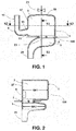
- Fig. 1 shows a front view of an air separator according to the present invention.
- the air separator 100 has an air separation chamber 1, which is divided into a first chamber 3 and a second chamber 5.
- the air separator 100 is exemplarily designed as a venous blood chamber.
- the first chamber 3 is arranged above the second chamber 5. This arrangement may correspond to the usual use of the air separator according to the invention.
- the first chamber 3 can therefore be referred to as an upper chamber in such an arrangement, the second chamber 5 as a lower chamber.
- connection opening 7 is arranged between the first chamber 3 and the second chamber 5.
- the connection opening 7 has a smaller flow cross-section Q than the second chamber 5.
- An inflow passage 9 is in fluid communication with the first chamber 3 and allows inflow of a fluid into the first chamber 3.
- the inflow channel 9 is provided in a lower region 11 of the first chamber 3.
- the inflow channel 9 has a widening 13.
- a longitudinal section of the expansion 13 has wider sections than a longitudinal section of the inflow channel 9 in an unexpanded region 15.
- fluid flows through the inflow passage 9 into the first chamber 3.
- an inflow or inflow of the fluid into the first chamber 3 is tangential to a side wall 17, as in particular from the 3 and 4 is apparent.
- the fluid flows toward an upper side or an upper region 19 of the first chamber 3.
- Air contained in the fluid is deposited in the first chamber 3, in particular in the upper region 19 of the first chamber 3, and can be removed from the first chamber 3 by a valve device 21.
- the fluid flows from the first chamber 3 through the communication port 7 into the second chamber 5. Due to the cross-sectional taper of the communication port 7 with respect to a chamber cross section of the second chamber 5 - or the smaller cross section, a smaller dimension or a smaller area of the passage opening, respectively opposite to the second chamber 5 - slows the flow velocity of the fluid after entering the second chamber. 5
- Air which has not yet been deposited in the first chamber 3 during the inflow of the fluid can be deposited in an upper region 23 of the second chamber 5. It can be guided through the first chamber 3 into the upper region 19 of the first chamber 3 or ascend into it and be removed from the first chamber 3 with the aid of the valve device 21.
- the second chamber 5 is connected to a discharge channel 25.
- the outflow channel 25 is preferably designed so that air, which has not been deposited in the first chamber 3 or in the second chamber 5, at standstill of the flow through the discharge channel 25 into the second chamber 5 and from there through the connection opening 7 in the first chamber 3 or in an upper region 19 thereof is discharged. It can be removed from there from the first chamber 3.
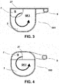
- Fig. 2 shows a side view of the air separator 100 according to the invention in the form of a longitudinal section through the air separator Fig. 1 along the marked there S1-S1 line.
- connection opening 7 is arranged off-center between the first chamber 3 and the second chamber 5. It also has a smaller flow cross section Q measured at a flow cross section QK1 of the first chamber 3. It also has a smaller flow cross section measured at a flow cross section QK2 of the second chamber.
- the air separator 100 has a cover device 27 on one side (the left side in FIG Fig. 2 ) on.
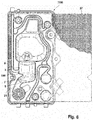
- Fig. 3 shows a cross section of the air separator 100 according to the present invention along a horizontal line of the air separator 100, which in Fig. 1 is marked as line S2-S2.
- This cross-section shows a view of the first chamber 3, wherein the viewer of the in Fig. 3 Shown from above on the air separator 100, so on an upper side of the same, looks.
- the cover device 27 is designed flat.
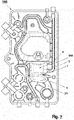
- Fig. 4 also shows a cross section of an air separator 100 according to the invention.
- FIG. 3 and FIG. 4 are substantially identical, except that the cover device 27 in Fig. 4 is executed curved.
- Fig. 5 shows a side view of an external functional device according to the invention, which at the surface, on the in Fig. 5 is provided with a cover device 27 is provided.
- the external functional device is here exemplarily designed as a blood treatment cassette 1000 with chambers, channels, valves and the like.
- the cover device 27 covers a front side of the blood treatment cassette 1000. It is exemplified as a film.
- the blood treatment cassette 1000 may be at least the same as in Fig. 5 shown front to a blood treatment device (in Fig. 5 not shown).
- the blood treatment cassette 1000 has an air separator 100 according to the invention.
- the air separator 100 has the first chamber 3 and the second chamber 5, which are separated from each other by the connection opening 7.
- the first chamber 3 is connected to the inflow channel 9, the second chamber 5 to the outflow channel 25.
- Fig. 6 shows the blood treatment cassette 1000 of Fig. 5 , wherein the cover device 27 on the left edge of the blood treatment cassette 1000 as well as above and below erförend cut and can be seen unfolded to the right.
- Fig. 6 shows the elements to be recognized in more detail in the interior of the blood treatment cassette 1000 after the foil has been cut open.
- Fig. 7 shows the blood treatment cassette 1000 from its back.
- the blood treatment cassette 1000 is coupled to the blood treatment device, a viewer will look at this rear side upon opening a door of the blood treatment device for removing the blood treatment cassette 1000.
- Fig. 8 shows schematically simplified another embodiment of the air separator 100 according to the invention.
- the inventive air separator 100 has a recess 133 or constriction or inclination change or taper or asymmetry of the inner and / or outer wall of the air separator 100 according to the invention.
- the indentation 133 is in Fig. 8 to recognize the right edge and at the front of the air separator 100 according to the invention.
- the indentation 133 can be located at least on the inflow line or the side opposite the inflow channel 9.
- the indentation 133 may relate to a portion of the circumference or the entire circumference of the hard part of the venous chamber.
- the indentation 133 may be substantially horizontal in a position of use of the blood cassette 1000.
- the indentation 133 may, in certain embodiments, correspond to or comprise a change in the circumference and / or diameter of a portion of the air separator 100 according to the invention or the wall thereof.
- the indentation 133 may be limited to the first chamber 3 in some embodiments.
- the indentation 133 may, in some embodiments, have a non-circular diameter of the air separator 100 according to the invention (at the level of the indentation 133) in a horizontal section (referring to the representation of the blood treatment cassette 1000 in FIG Fig. 8 or an arrangement of the blood treatment cassette 1000 in use).
- the indentation 133 may, in certain embodiments, be an asymmetrical shape of the air separator 100 according to the invention as measured by the illustration of FIG Fig. 8 lead in up-down direction.
- the indentation 133 which can run partially or completely over the entire cross section of the air separator 100 according to the invention, has surprisingly led to a reduced foam formation within the air separator 100 according to the invention.
- an improved venting can be achieved be achieved before the start of treatment.
- improved steam flow during sterilization can be achieved.
- a reduction of dead water areas can be achieved with the known advantages associated therewith.
Landscapes
- Health & Medical Sciences (AREA)
- Heart & Thoracic Surgery (AREA)
- Vascular Medicine (AREA)
- Biomedical Technology (AREA)
- Engineering & Computer Science (AREA)
- Anesthesiology (AREA)
- Cardiology (AREA)
- Hematology (AREA)
- Life Sciences & Earth Sciences (AREA)
- Animal Behavior & Ethology (AREA)
- General Health & Medical Sciences (AREA)
- Public Health (AREA)
- Veterinary Medicine (AREA)
- External Artificial Organs (AREA)
- Acyclic And Carbocyclic Compounds In Medicinal Compositions (AREA)
Applications Claiming Priority (5)
| Application Number | Priority Date | Filing Date | Title |
|---|---|---|---|
| DE102009018664A DE102009018664A1 (de) | 2009-04-23 | 2009-04-23 | Externe Funktionseinrichtung, Blutbehandlungsvorrichtung zum Aufnehmen einer erfindungsgemäßen externen Funktionseinrichtung, sowie Verfahren |
| US18560809P | 2009-06-10 | 2009-06-10 | |
| DE102009024465.4A DE102009024465B4 (de) | 2009-06-10 | 2009-06-10 | Blutkassette mit Luftabscheider, Blutkreislauf sowie Behandlungsvorrichtung |
| EP10716488.1A EP2421584B1 (fr) | 2009-04-23 | 2010-04-21 | Séparateur d'air, dispositif fonctionnel externe, système de circulation sanguine, et dispositif de traitement |
| PCT/EP2010/002486 WO2010121817A1 (fr) | 2009-04-23 | 2010-04-21 | Séparateur d'air, dispositif fonctionnel externe, système de circulation sanguine, et dispositif de traitement |
Related Parent Applications (1)
| Application Number | Title | Priority Date | Filing Date |
|---|---|---|---|
| EP10716488.1A Division EP2421584B1 (fr) | 2009-04-23 | 2010-04-21 | Séparateur d'air, dispositif fonctionnel externe, système de circulation sanguine, et dispositif de traitement |
Publications (2)
| Publication Number | Publication Date |
|---|---|
| EP3088022A1 true EP3088022A1 (fr) | 2016-11-02 |
| EP3088022B1 EP3088022B1 (fr) | 2020-09-30 |
Family
ID=42990959
Family Applications (2)
| Application Number | Title | Priority Date | Filing Date |
|---|---|---|---|
| EP10716488.1A Active EP2421584B1 (fr) | 2009-04-23 | 2010-04-21 | Séparateur d'air, dispositif fonctionnel externe, système de circulation sanguine, et dispositif de traitement |
| EP16164974.4A Active EP3088022B1 (fr) | 2009-04-23 | 2010-04-21 | Separateur d'air, dispositif de fonctionnement externe, dispositif de traitement et de circulation sanguine |
Family Applications Before (1)
| Application Number | Title | Priority Date | Filing Date |
|---|---|---|---|
| EP10716488.1A Active EP2421584B1 (fr) | 2009-04-23 | 2010-04-21 | Séparateur d'air, dispositif fonctionnel externe, système de circulation sanguine, et dispositif de traitement |
Country Status (11)
| Country | Link |
|---|---|
| US (1) | US8308856B2 (fr) |
| EP (2) | EP2421584B1 (fr) |
| JP (3) | JP5825578B2 (fr) |
| CN (1) | CN102405071B (fr) |
| AR (1) | AR079773A1 (fr) |
| ES (1) | ES2582030T3 (fr) |
| HU (1) | HUE029690T2 (fr) |
| PL (1) | PL2421584T3 (fr) |
| PT (1) | PT2421584T (fr) |
| TW (1) | TWI566794B (fr) |
| WO (1) | WO2010121817A1 (fr) |
Families Citing this family (13)
| Publication number | Priority date | Publication date | Assignee | Title |
|---|---|---|---|---|
| WO2010121740A1 (fr) * | 2009-04-23 | 2010-10-28 | Fresenius Medical Care Deutschland Gmbh | Dispositif récepteur pour la réception de fluides médicaux, dispositif fonctionnel externe, et dispositif de traitement médical |
| EP2448615B1 (fr) * | 2009-07-03 | 2019-12-11 | Embody AB | Réducteur de bulles pour élimination des bulles de gaz provenant d'un écoulement |
| PL2766064T3 (pl) | 2011-12-08 | 2017-08-31 | Alcon Research, Ltd. | Selektywnie przemieszczalne elementy zaworowe dla obwodów zasysania i irygacji |
| USD698019S1 (en) | 2013-03-05 | 2014-01-21 | Alcon Research, Ltd. | Ophthalmic surgical cassette |
| US9549850B2 (en) | 2013-04-26 | 2017-01-24 | Novartis Ag | Partial venting system for occlusion surge mitigation |
| JP2015085181A (ja) * | 2013-09-25 | 2015-05-07 | 川澄化学工業株式会社 | ドリップチャンバ |
| DE102014002578A1 (de) * | 2014-02-26 | 2015-08-27 | Fresenius Medical Care Deutschland Gmbh | Medizinische Flüssigkeitskassette und medizinischer Schlauchsatz mit medizinischer Flüssigkeitskassette |
| DE102014103506A1 (de) | 2014-03-14 | 2015-09-17 | Fresenius Medical Care Deutschland Gmbh | Blutbehandlungskassette mit gedelltem Folienventil sowie Blutbehandlungsvorrichtung |
| US10179213B2 (en) | 2015-05-27 | 2019-01-15 | Vital Signs, Inc. | Apparatus and methods for intravenous gas elimination |
| US10625009B2 (en) * | 2016-02-17 | 2020-04-21 | Baxter International Inc. | Airtrap, system and method for removing microbubbles from a fluid stream |
| DE102017102175A1 (de) * | 2017-02-03 | 2018-08-09 | B. Braun Avitum Ag | Luftabscheider mit Zwangszirkulation |
| JP7597485B2 (ja) * | 2020-12-22 | 2024-12-10 | 旭化成メディカル株式会社 | 計量チャンバー及び液体処理装置 |
| DE102024115654A1 (de) * | 2024-06-05 | 2025-12-11 | Viessmann Holding International GmbH | Gasabscheidungsvorrichtung und Versorgungssystem |
Citations (4)
| Publication number | Priority date | Publication date | Assignee | Title |
|---|---|---|---|---|
| US5591251A (en) * | 1993-11-29 | 1997-01-07 | Cobe Laboratories, Inc. | Side flow bubble trap apparatus and method |
| JP2000270709A (ja) * | 1999-03-24 | 2000-10-03 | Guppy:Kk | 流体境界域の連通部構造、孵化槽及び水生動物飼育槽 |
| DE10224750A1 (de) * | 2002-06-04 | 2003-12-24 | Fresenius Medical Care De Gmbh | Vorrichtung zur Behandlung einer medizinischen Flüssigkeit |
| US20050261619A1 (en) * | 2004-05-24 | 2005-11-24 | Terumo Cardiovascular Systems Corporation | Vortex-flow air removal in a blood perfusion system |
Family Cites Families (26)
| Publication number | Priority date | Publication date | Assignee | Title |
|---|---|---|---|---|
| DE8309374U1 (de) | 1983-12-22 | F.A. Sening (GmbH & Co), 2000 Hamburg | Abgabevorrichtung für Tankwagen | |
| DE2420599A1 (de) | 1974-04-27 | 1975-10-30 | Haar Maschbau Alfons | Gasmessverhueter |
| US4137160A (en) * | 1974-10-31 | 1979-01-30 | Baxter Travenol Laboratories, Inc. | Device for separating low density material such as gas bubbles from a liquid, and the use thereof in a dialysis delivery system |
| US4345919A (en) * | 1981-01-19 | 1982-08-24 | Texas Medical Products, Inc. | Degasser for biological fluids |
| US4365635A (en) * | 1981-03-03 | 1982-12-28 | Bell & Howell Company | Pressure transducing methods and apparatus |
| JPS6081546U (ja) * | 1983-11-09 | 1985-06-06 | 株式会社ウベ循研 | 体外循環血液用濾過器 |
| AU611244B2 (en) * | 1987-12-25 | 1991-06-06 | Terumo Kabushiki Kaisha | Medical instrument |
| US4936759A (en) * | 1989-01-23 | 1990-06-26 | Minnesota Mining And Manufacturing Company | Blood reservoir/pump |
| US5258127A (en) * | 1990-07-27 | 1993-11-02 | Pall Corporation | Leucocyte depleting filter device and method of use |
| US5496299A (en) * | 1994-09-21 | 1996-03-05 | C. R. Bard, Inc. | Suction reservoir |
| JP3128724B2 (ja) * | 1995-03-24 | 2001-01-29 | サンウエーブ工業株式会社 | 家具用把手 |
| US5769815A (en) * | 1995-05-25 | 1998-06-23 | Medisystems Technology Corporation | Blood chamber with integral projections |
| DE19650407A1 (de) * | 1996-12-05 | 1998-06-10 | Kevin Business Corp | Blut-Gas-Trennverfahren und -Trennvorrichtung |
| US6258408B1 (en) * | 1999-07-06 | 2001-07-10 | Arun Madan | Semiconductor vacuum deposition system and method having a reel-to-reel substrate cassette |
| US6663613B1 (en) * | 2000-01-25 | 2003-12-16 | Bacchus Vascular, Inc. | System and methods for clot dissolution |
| US6773670B2 (en) * | 2001-02-09 | 2004-08-10 | Cardiovention, Inc. C/O The Brenner Group, Inc. | Blood filter having a sensor for active gas removal and methods of use |
| ITMI20030214A1 (it) * | 2003-02-07 | 2004-08-08 | Gambro Lundia Ab | Elemento di supporto per un modulo integrato |
| US7722577B2 (en) * | 2005-02-18 | 2010-05-25 | Becton, Dickinson And Company | Bubble free—self primed IV set |
| JP3128724U (ja) * | 2006-09-15 | 2007-01-25 | 川澄化学工業株式会社 | ドリップチャンバ |
| US7901376B2 (en) * | 2007-07-05 | 2011-03-08 | Baxter International Inc. | Dialysis cassette having multiple outlet valve |
| US7871462B2 (en) * | 2007-10-01 | 2011-01-18 | Baxter International Inc. | Dialysis systems having air separation chambers with internal structures to enhance air removal |
| US7892331B2 (en) * | 2007-10-01 | 2011-02-22 | Baxter International Inc. | Dialysis systems having air separation chambers with internal structures to enhance air removal |
| US7892332B2 (en) * | 2007-10-01 | 2011-02-22 | Baxter International Inc. | Dialysis systems having air traps with internal structures to enhance air removal |
| DE102009012632A1 (de) | 2009-03-10 | 2010-09-23 | Fresenius Medical Care Deutschland Gmbh | Abdichtungseinrichtung zum Abdichten eines Volumens einer medizinischen Behandlungsanordnung gegen ein weiteres Volumen sowie Anordnung und Verfahren |
| DE102009024468A1 (de) | 2009-06-10 | 2010-12-16 | Fresenius Medical Care Deutschland Gmbh | Externe Funktionseinrichtung, Blutbehandlungsvorrichtung zum Aufnehmen einer erfindungsgemäßen externen Funktionseinrichtung, sowie Verfahren |
| DE102009018664A1 (de) | 2009-04-23 | 2010-10-28 | Fresenius Medical Care Deutschland Gmbh | Externe Funktionseinrichtung, Blutbehandlungsvorrichtung zum Aufnehmen einer erfindungsgemäßen externen Funktionseinrichtung, sowie Verfahren |
-
2010
- 2010-04-21 HU HUE10716488A patent/HUE029690T2/en unknown
- 2010-04-21 PT PT107164881T patent/PT2421584T/pt unknown
- 2010-04-21 EP EP10716488.1A patent/EP2421584B1/fr active Active
- 2010-04-21 EP EP16164974.4A patent/EP3088022B1/fr active Active
- 2010-04-21 CN CN201080017596.6A patent/CN102405071B/zh active Active
- 2010-04-21 ES ES10716488.1T patent/ES2582030T3/es active Active
- 2010-04-21 WO PCT/EP2010/002486 patent/WO2010121817A1/fr not_active Ceased
- 2010-04-21 JP JP2012506398A patent/JP5825578B2/ja not_active Expired - Fee Related
- 2010-04-21 PL PL10716488.1T patent/PL2421584T3/pl unknown
- 2010-04-22 AR ARP100101332A patent/AR079773A1/es active IP Right Grant
- 2010-04-23 US US12/765,926 patent/US8308856B2/en active Active
- 2010-04-23 TW TW099112813A patent/TWI566794B/zh active
-
2015
- 2015-05-29 JP JP2015109941A patent/JP2015180284A/ja active Pending
-
2017
- 2017-03-16 JP JP2017051553A patent/JP6573928B2/ja active Active
Patent Citations (4)
| Publication number | Priority date | Publication date | Assignee | Title |
|---|---|---|---|---|
| US5591251A (en) * | 1993-11-29 | 1997-01-07 | Cobe Laboratories, Inc. | Side flow bubble trap apparatus and method |
| JP2000270709A (ja) * | 1999-03-24 | 2000-10-03 | Guppy:Kk | 流体境界域の連通部構造、孵化槽及び水生動物飼育槽 |
| DE10224750A1 (de) * | 2002-06-04 | 2003-12-24 | Fresenius Medical Care De Gmbh | Vorrichtung zur Behandlung einer medizinischen Flüssigkeit |
| US20050261619A1 (en) * | 2004-05-24 | 2005-11-24 | Terumo Cardiovascular Systems Corporation | Vortex-flow air removal in a blood perfusion system |
Also Published As
| Publication number | Publication date |
|---|---|
| PT2421584T (pt) | 2016-07-18 |
| JP2015180284A (ja) | 2015-10-15 |
| AR079773A1 (es) | 2012-02-22 |
| ES2582030T3 (es) | 2016-09-08 |
| JP5825578B2 (ja) | 2015-12-02 |
| PL2421584T3 (pl) | 2016-11-30 |
| WO2010121817A1 (fr) | 2010-10-28 |
| EP2421584B1 (fr) | 2016-04-13 |
| JP2012524562A (ja) | 2012-10-18 |
| HUE029690T2 (en) | 2017-03-28 |
| CN102405071A (zh) | 2012-04-04 |
| TWI566794B (zh) | 2017-01-21 |
| US8308856B2 (en) | 2012-11-13 |
| US20100269702A1 (en) | 2010-10-28 |
| JP2017140413A (ja) | 2017-08-17 |
| EP3088022B1 (fr) | 2020-09-30 |
| CN102405071B (zh) | 2016-01-20 |
| EP2421584A1 (fr) | 2012-02-29 |
| JP6573928B2 (ja) | 2019-09-11 |
| TW201039871A (en) | 2010-11-16 |
Similar Documents
| Publication | Publication Date | Title |
|---|---|---|
| EP2421584B1 (fr) | Séparateur d'air, dispositif fonctionnel externe, système de circulation sanguine, et dispositif de traitement | |
| DE102009024465B4 (de) | Blutkassette mit Luftabscheider, Blutkreislauf sowie Behandlungsvorrichtung | |
| DE69214325T2 (de) | Vorrichtung zur Entfernung von Gasblasen aus einer zirkulierenden Flüssigkeit | |
| EP0646380B1 (fr) | Séparateur d'air | |
| EP0728509B1 (fr) | Dispositif pour éliminer les bulles de gaz d'un liquide médical | |
| DE3214397C2 (de) | Perfusions-Doppellumenkatheter | |
| DE69529278T3 (de) | Filtrationsvorrichtung zur entfernung von leukozyten | |
| EP2536448B1 (fr) | Élément de couplage pour assemblage à tuyau de drainage | |
| DE19620591B4 (de) | Vorrichtung zum Entfernen von Gasen aus Flüssigkeiten | |
| DE19617036C2 (de) | Vorrichtung zum Abscheiden von Gasblasen aus Blut | |
| DE68925020T2 (de) | Drainagevorrichtung. | |
| EP2421574B1 (fr) | Piège à caillots, dispositif fonctionnel externe, circuit sanguin et dispositif de traitement | |
| DE60317688T2 (de) | FLüSSIGKEITS-PROBENEHMER UND VERFAHREN | |
| EP3263154B1 (fr) | Dispositif de purge d'air et de vidange rapide d'un filtre | |
| EP2763741B1 (fr) | Dispositif de connexion rapide | |
| DE8231889U1 (de) | Blutkreislauf fuer eine kuenstliche lunge vom membrantyp sowie behaelter hierfuer | |
| DE102009024495A1 (de) | Gerinnselfänger, externe Funktionseinrichtung, Blutkreislauf sowie Behandlungsvorrichtung | |
| DE19506506C2 (de) | Vorrichtung zum Abscheiden von Luftblasen aus medizinischen Flüssigkeiten | |
| DE60305763T2 (de) | Venöse Blutkammer in einem extrakorporalen Kreislauf | |
| DE102005011740B4 (de) | Venöse Blasenfalle | |
| EP2421580A1 (fr) | Dispositif récepteur pour la réception de fluides médicaux, dispositif fonctionnel externe, et dispositif de traitement médical | |
| DE69631767T2 (de) | Drainageeinheit mit geregeltem unterdruck | |
| DE102020116247A1 (de) | Schlaucheinsatzstück für einen hydraulikschlauchsatz einer blutbehandlungsvorrichtung | |
| DE102009024466A1 (de) | Aufnahmeeinrichtung zum Aufnehmen von medizinischen Fluiden sowie externe Funktionseinrichtung und medizinische Behandlungsvorrichtung | |
| DE102019131369A1 (de) | Oxygenatorvorrichtung |
Legal Events
| Date | Code | Title | Description |
|---|---|---|---|
| PUAI | Public reference made under article 153(3) epc to a published international application that has entered the european phase |
Free format text: ORIGINAL CODE: 0009012 |
|
| AC | Divisional application: reference to earlier application |
Ref document number: 2421584 Country of ref document: EP Kind code of ref document: P |
|
| AK | Designated contracting states |
Kind code of ref document: A1 Designated state(s): AT BE BG CH CY CZ DE DK EE ES FI FR GB GR HR HU IE IS IT LI LT LU LV MC MK MT NL NO PL PT RO SE SI SK SM TR |
|
| STAA | Information on the status of an ep patent application or granted ep patent |
Free format text: STATUS: REQUEST FOR EXAMINATION WAS MADE |
|
| 17P | Request for examination filed |
Effective date: 20170424 |
|
| RBV | Designated contracting states (corrected) |
Designated state(s): AT BE BG CH CY CZ DE DK EE ES FI FR GB GR HR HU IE IS IT LI LT LU LV MC MK MT NL NO PL PT RO SE SI SK SM TR |
|
| STAA | Information on the status of an ep patent application or granted ep patent |
Free format text: STATUS: EXAMINATION IS IN PROGRESS |
|
| 17Q | First examination report despatched |
Effective date: 20180823 |
|
| GRAP | Despatch of communication of intention to grant a patent |
Free format text: ORIGINAL CODE: EPIDOSNIGR1 |
|
| STAA | Information on the status of an ep patent application or granted ep patent |
Free format text: STATUS: GRANT OF PATENT IS INTENDED |
|
| INTG | Intention to grant announced |
Effective date: 20190725 |
|
| GRAS | Grant fee paid |
Free format text: ORIGINAL CODE: EPIDOSNIGR3 |
|
| GRAJ | Information related to disapproval of communication of intention to grant by the applicant or resumption of examination proceedings by the epo deleted |
Free format text: ORIGINAL CODE: EPIDOSDIGR1 |
|
| GRAL | Information related to payment of fee for publishing/printing deleted |
Free format text: ORIGINAL CODE: EPIDOSDIGR3 |
|
| GRAP | Despatch of communication of intention to grant a patent |
Free format text: ORIGINAL CODE: EPIDOSNIGR1 |
|
| INTC | Intention to grant announced (deleted) | ||
| INTG | Intention to grant announced |
Effective date: 20191210 |
|
| GRAJ | Information related to disapproval of communication of intention to grant by the applicant or resumption of examination proceedings by the epo deleted |
Free format text: ORIGINAL CODE: EPIDOSDIGR1 |
|
| GRAL | Information related to payment of fee for publishing/printing deleted |
Free format text: ORIGINAL CODE: EPIDOSDIGR3 |
|
| STAA | Information on the status of an ep patent application or granted ep patent |
Free format text: STATUS: EXAMINATION IS IN PROGRESS |
|
| GRAP | Despatch of communication of intention to grant a patent |
Free format text: ORIGINAL CODE: EPIDOSNIGR1 |
|
| STAA | Information on the status of an ep patent application or granted ep patent |
Free format text: STATUS: GRANT OF PATENT IS INTENDED |
|
| INTC | Intention to grant announced (deleted) | ||
| INTG | Intention to grant announced |
Effective date: 20200428 |
|
| GRAS | Grant fee paid |
Free format text: ORIGINAL CODE: EPIDOSNIGR3 |
|
| GRAA | (expected) grant |
Free format text: ORIGINAL CODE: 0009210 |
|
| STAA | Information on the status of an ep patent application or granted ep patent |
Free format text: STATUS: THE PATENT HAS BEEN GRANTED |
|
| AC | Divisional application: reference to earlier application |
Ref document number: 2421584 Country of ref document: EP Kind code of ref document: P |
|
| AK | Designated contracting states |
Kind code of ref document: B1 Designated state(s): AT BE BG CH CY CZ DE DK EE ES FI FR GB GR HR HU IE IS IT LI LT LU LV MC MK MT NL NO PL PT RO SE SI SK SM TR |
|
| REG | Reference to a national code |
Ref country code: CH Ref legal event code: EP Ref country code: GB Ref legal event code: FG4D Free format text: NOT ENGLISH |
|
| REG | Reference to a national code |
Ref country code: AT Ref legal event code: REF Ref document number: 1318140 Country of ref document: AT Kind code of ref document: T Effective date: 20201015 |
|
| REG | Reference to a national code |
Ref country code: DE Ref legal event code: R096 Ref document number: 502010016764 Country of ref document: DE |
|
| REG | Reference to a national code |
Ref country code: IE Ref legal event code: FG4D Free format text: LANGUAGE OF EP DOCUMENT: GERMAN |
|
| REG | Reference to a national code |
Ref country code: CH Ref legal event code: NV Representative=s name: P&TS SA, CH |
|
| PG25 | Lapsed in a contracting state [announced via postgrant information from national office to epo] |
Ref country code: FI Free format text: LAPSE BECAUSE OF FAILURE TO SUBMIT A TRANSLATION OF THE DESCRIPTION OR TO PAY THE FEE WITHIN THE PRESCRIBED TIME-LIMIT Effective date: 20200930 Ref country code: HR Free format text: LAPSE BECAUSE OF FAILURE TO SUBMIT A TRANSLATION OF THE DESCRIPTION OR TO PAY THE FEE WITHIN THE PRESCRIBED TIME-LIMIT Effective date: 20200930 Ref country code: SE Free format text: LAPSE BECAUSE OF FAILURE TO SUBMIT A TRANSLATION OF THE DESCRIPTION OR TO PAY THE FEE WITHIN THE PRESCRIBED TIME-LIMIT Effective date: 20200930 Ref country code: NO Free format text: LAPSE BECAUSE OF FAILURE TO SUBMIT A TRANSLATION OF THE DESCRIPTION OR TO PAY THE FEE WITHIN THE PRESCRIBED TIME-LIMIT Effective date: 20201230 Ref country code: BG Free format text: LAPSE BECAUSE OF FAILURE TO SUBMIT A TRANSLATION OF THE DESCRIPTION OR TO PAY THE FEE WITHIN THE PRESCRIBED TIME-LIMIT Effective date: 20201230 Ref country code: GR Free format text: LAPSE BECAUSE OF FAILURE TO SUBMIT A TRANSLATION OF THE DESCRIPTION OR TO PAY THE FEE WITHIN THE PRESCRIBED TIME-LIMIT Effective date: 20201231 |
|
| PG25 | Lapsed in a contracting state [announced via postgrant information from national office to epo] |
Ref country code: LV Free format text: LAPSE BECAUSE OF FAILURE TO SUBMIT A TRANSLATION OF THE DESCRIPTION OR TO PAY THE FEE WITHIN THE PRESCRIBED TIME-LIMIT Effective date: 20200930 |
|
| REG | Reference to a national code |
Ref country code: NL Ref legal event code: MP Effective date: 20200930 |
|
| REG | Reference to a national code |
Ref country code: LT Ref legal event code: MG4D |
|
| PG25 | Lapsed in a contracting state [announced via postgrant information from national office to epo] |
Ref country code: NL Free format text: LAPSE BECAUSE OF FAILURE TO SUBMIT A TRANSLATION OF THE DESCRIPTION OR TO PAY THE FEE WITHIN THE PRESCRIBED TIME-LIMIT Effective date: 20200930 Ref country code: LT Free format text: LAPSE BECAUSE OF FAILURE TO SUBMIT A TRANSLATION OF THE DESCRIPTION OR TO PAY THE FEE WITHIN THE PRESCRIBED TIME-LIMIT Effective date: 20200930 Ref country code: RO Free format text: LAPSE BECAUSE OF FAILURE TO SUBMIT A TRANSLATION OF THE DESCRIPTION OR TO PAY THE FEE WITHIN THE PRESCRIBED TIME-LIMIT Effective date: 20200930 Ref country code: PT Free format text: LAPSE BECAUSE OF FAILURE TO SUBMIT A TRANSLATION OF THE DESCRIPTION OR TO PAY THE FEE WITHIN THE PRESCRIBED TIME-LIMIT Effective date: 20210201 Ref country code: SM Free format text: LAPSE BECAUSE OF FAILURE TO SUBMIT A TRANSLATION OF THE DESCRIPTION OR TO PAY THE FEE WITHIN THE PRESCRIBED TIME-LIMIT Effective date: 20200930 Ref country code: EE Free format text: LAPSE BECAUSE OF FAILURE TO SUBMIT A TRANSLATION OF THE DESCRIPTION OR TO PAY THE FEE WITHIN THE PRESCRIBED TIME-LIMIT Effective date: 20200930 Ref country code: CZ Free format text: LAPSE BECAUSE OF FAILURE TO SUBMIT A TRANSLATION OF THE DESCRIPTION OR TO PAY THE FEE WITHIN THE PRESCRIBED TIME-LIMIT Effective date: 20200930 |
|
| PG25 | Lapsed in a contracting state [announced via postgrant information from national office to epo] |
Ref country code: ES Free format text: LAPSE BECAUSE OF FAILURE TO SUBMIT A TRANSLATION OF THE DESCRIPTION OR TO PAY THE FEE WITHIN THE PRESCRIBED TIME-LIMIT Effective date: 20200930 Ref country code: PL Free format text: LAPSE BECAUSE OF FAILURE TO SUBMIT A TRANSLATION OF THE DESCRIPTION OR TO PAY THE FEE WITHIN THE PRESCRIBED TIME-LIMIT Effective date: 20200930 Ref country code: IS Free format text: LAPSE BECAUSE OF FAILURE TO SUBMIT A TRANSLATION OF THE DESCRIPTION OR TO PAY THE FEE WITHIN THE PRESCRIBED TIME-LIMIT Effective date: 20210130 |
|
| PG25 | Lapsed in a contracting state [announced via postgrant information from national office to epo] |
Ref country code: SK Free format text: LAPSE BECAUSE OF FAILURE TO SUBMIT A TRANSLATION OF THE DESCRIPTION OR TO PAY THE FEE WITHIN THE PRESCRIBED TIME-LIMIT Effective date: 20200930 |
|
| REG | Reference to a national code |
Ref country code: DE Ref legal event code: R097 Ref document number: 502010016764 Country of ref document: DE |
|
| PLBE | No opposition filed within time limit |
Free format text: ORIGINAL CODE: 0009261 |
|
| STAA | Information on the status of an ep patent application or granted ep patent |
Free format text: STATUS: NO OPPOSITION FILED WITHIN TIME LIMIT |
|
| PG25 | Lapsed in a contracting state [announced via postgrant information from national office to epo] |
Ref country code: DK Free format text: LAPSE BECAUSE OF FAILURE TO SUBMIT A TRANSLATION OF THE DESCRIPTION OR TO PAY THE FEE WITHIN THE PRESCRIBED TIME-LIMIT Effective date: 20200930 |
|
| 26N | No opposition filed |
Effective date: 20210701 |
|
| PG25 | Lapsed in a contracting state [announced via postgrant information from national office to epo] |
Ref country code: MC Free format text: LAPSE BECAUSE OF FAILURE TO SUBMIT A TRANSLATION OF THE DESCRIPTION OR TO PAY THE FEE WITHIN THE PRESCRIBED TIME-LIMIT Effective date: 20200930 Ref country code: SI Free format text: LAPSE BECAUSE OF FAILURE TO SUBMIT A TRANSLATION OF THE DESCRIPTION OR TO PAY THE FEE WITHIN THE PRESCRIBED TIME-LIMIT Effective date: 20200930 |
|
| GBPC | Gb: european patent ceased through non-payment of renewal fee |
Effective date: 20210421 |
|
| PG25 | Lapsed in a contracting state [announced via postgrant information from national office to epo] |
Ref country code: LU Free format text: LAPSE BECAUSE OF NON-PAYMENT OF DUE FEES Effective date: 20210421 |
|
| REG | Reference to a national code |
Ref country code: BE Ref legal event code: MM Effective date: 20210430 |
|
| PG25 | Lapsed in a contracting state [announced via postgrant information from national office to epo] |
Ref country code: LI Free format text: LAPSE BECAUSE OF NON-PAYMENT OF DUE FEES Effective date: 20210430 Ref country code: CH Free format text: LAPSE BECAUSE OF NON-PAYMENT OF DUE FEES Effective date: 20210430 Ref country code: GB Free format text: LAPSE BECAUSE OF NON-PAYMENT OF DUE FEES Effective date: 20210421 |
|
| PG25 | Lapsed in a contracting state [announced via postgrant information from national office to epo] |
Ref country code: IE Free format text: LAPSE BECAUSE OF NON-PAYMENT OF DUE FEES Effective date: 20210421 |
|
| PG25 | Lapsed in a contracting state [announced via postgrant information from national office to epo] |
Ref country code: IS Free format text: LAPSE BECAUSE OF FAILURE TO SUBMIT A TRANSLATION OF THE DESCRIPTION OR TO PAY THE FEE WITHIN THE PRESCRIBED TIME-LIMIT Effective date: 20210130 |
|
| REG | Reference to a national code |
Ref country code: AT Ref legal event code: MM01 Ref document number: 1318140 Country of ref document: AT Kind code of ref document: T Effective date: 20210421 |
|
| PG25 | Lapsed in a contracting state [announced via postgrant information from national office to epo] |
Ref country code: BE Free format text: LAPSE BECAUSE OF NON-PAYMENT OF DUE FEES Effective date: 20210430 |
|
| PG25 | Lapsed in a contracting state [announced via postgrant information from national office to epo] |
Ref country code: AT Free format text: LAPSE BECAUSE OF NON-PAYMENT OF DUE FEES Effective date: 20210421 |
|
| PG25 | Lapsed in a contracting state [announced via postgrant information from national office to epo] |
Ref country code: HU Free format text: LAPSE BECAUSE OF FAILURE TO SUBMIT A TRANSLATION OF THE DESCRIPTION OR TO PAY THE FEE WITHIN THE PRESCRIBED TIME-LIMIT; INVALID AB INITIO Effective date: 20100421 Ref country code: CY Free format text: LAPSE BECAUSE OF FAILURE TO SUBMIT A TRANSLATION OF THE DESCRIPTION OR TO PAY THE FEE WITHIN THE PRESCRIBED TIME-LIMIT Effective date: 20200930 |
|
| P01 | Opt-out of the competence of the unified patent court (upc) registered |
Effective date: 20230602 |
|
| PG25 | Lapsed in a contracting state [announced via postgrant information from national office to epo] |
Ref country code: MK Free format text: LAPSE BECAUSE OF FAILURE TO SUBMIT A TRANSLATION OF THE DESCRIPTION OR TO PAY THE FEE WITHIN THE PRESCRIBED TIME-LIMIT Effective date: 20200930 |
|
| PG25 | Lapsed in a contracting state [announced via postgrant information from national office to epo] |
Ref country code: TR Free format text: LAPSE BECAUSE OF FAILURE TO SUBMIT A TRANSLATION OF THE DESCRIPTION OR TO PAY THE FEE WITHIN THE PRESCRIBED TIME-LIMIT Effective date: 20200930 |
|
| PG25 | Lapsed in a contracting state [announced via postgrant information from national office to epo] |
Ref country code: MT Free format text: LAPSE BECAUSE OF FAILURE TO SUBMIT A TRANSLATION OF THE DESCRIPTION OR TO PAY THE FEE WITHIN THE PRESCRIBED TIME-LIMIT Effective date: 20200930 |
|
| PGFP | Annual fee paid to national office [announced via postgrant information from national office to epo] |
Ref country code: DE Payment date: 20250319 Year of fee payment: 16 |
|
| PGFP | Annual fee paid to national office [announced via postgrant information from national office to epo] |
Ref country code: IT Payment date: 20260319 Year of fee payment: 17 |
|
| PGFP | Annual fee paid to national office [announced via postgrant information from national office to epo] |
Ref country code: FR Payment date: 20260319 Year of fee payment: 17 |