EP3088064B1 - Programme de génération de signaux de vibration, système de génération de signaux de vibration, appareil de génération de signaux de vibration, procédé de génération de signaux de vibration et programme de sortie de données - Google Patents
Programme de génération de signaux de vibration, système de génération de signaux de vibration, appareil de génération de signaux de vibration, procédé de génération de signaux de vibration et programme de sortie de données Download PDFInfo
- Publication number
- EP3088064B1 EP3088064B1 EP16163513.1A EP16163513A EP3088064B1 EP 3088064 B1 EP3088064 B1 EP 3088064B1 EP 16163513 A EP16163513 A EP 16163513A EP 3088064 B1 EP3088064 B1 EP 3088064B1
- Authority
- EP
- European Patent Office
- Prior art keywords
- vibration
- data
- vibration signal
- frequency
- amplitude
- Prior art date
- Legal status (The legal status is an assumption and is not a legal conclusion. Google has not performed a legal analysis and makes no representation as to the accuracy of the status listed.)
- Active
Links
Images


Classifications
-
- A—HUMAN NECESSITIES
- A63—SPORTS; GAMES; AMUSEMENTS
- A63F—CARD, BOARD, OR ROULETTE GAMES; INDOOR GAMES USING SMALL MOVING PLAYING BODIES; VIDEO GAMES; GAMES NOT OTHERWISE PROVIDED FOR
- A63F13/00—Video games, i.e. games using an electronically generated display having two or more dimensions
- A63F13/25—Output arrangements for video game devices
- A63F13/28—Output arrangements for video game devices responding to control signals received from the game device for affecting ambient conditions, e.g. for vibrating players' seats, activating scent dispensers or affecting temperature or light
- A63F13/285—Generating tactile feedback signals via the game input device, e.g. force feedback
-
- H—ELECTRICITY
- H04—ELECTRIC COMMUNICATION TECHNIQUE
- H04L—TRANSMISSION OF DIGITAL INFORMATION, e.g. TELEGRAPHIC COMMUNICATION
- H04L27/00—Modulated-carrier systems
- H04L27/02—Amplitude-modulated carrier systems, e.g. using on-off keying; Single sideband or vestigial sideband modulation
Definitions
- the present invention relates to a vibration signal generation program, a vibration signal generation system, a vibration signal generation apparatus, a vibration signal generation method, and a data output program, and in particular, relates to a vibration signal generation program, a vibration signal generation system, a vibration signal generation apparatus, a vibration signal generation method, and a data output program that are related to, for example, a vibration to be imparted to a user.
- Patent Literature 1 Japanese Unexamined Patent Application Publication No. 2006-68210
- Patent Literature 1 Japanese Unexamined Patent Application Publication No. 2006-68210
- Patent Literature 1 The conventional game apparatus as disclosed in Patent Literature 1, however, does not impart the vibration by changing its frequency, its pulse width, or its amplitude. Further, the method for treating data when the frequency, the pulse width, or the amplitude is changed is not disclosed.
- WO 01/24158 A1 discloses controlling haptic sensations for vibrotectile feedback interface devices wherein magnitude and frequency can be adjusted independently of each other.
- the vibration signal generation program is executed by a computer included in an apparatus for generating a vibration signal for vibrating a vibration apparatus.
- the vibration signal generation program causes the computer to function as data acquisition means, decoding means, and vibration signal generation means.
- the data acquisition means acquires first data obtained by encoding amplitude modulation information indicating a change in an amplitude.
- the decoding means decodes the acquired first data.
- the vibration signal generation means generates a vibration signal using the decoded amplitude modulation information.
- the vibration signal generation means may generate the vibration signal using waveform data indicating a predetermined waveform in which a value greater than a reference value and a value smaller than the reference value are repeated, and the amplitude modulation information.
- positive and negative values may be repeated.
- an amplitude may be constant.
- the predetermined waveform may be a sine wave in which an amplitude is constant.
- the predetermined waveform may be a rectangular wave in which an amplitude is constant.
- the predetermined waveform may be a waveform having substantially the same frequency as a resonance frequency of the vibration apparatus.
- the vibration signal generation means may generate a current vibration signal using the decoded amplitude modulation and an amplitude of the previously generated vibration signal.
- the data acquisition means may acquire, as the first data, data obtained by encoding amplitude modulation information with respect to each of different frequency ranges.
- the decoding means may decode the first data acquired with respect to each frequency range.
- the vibration signal generation means may generate the vibration signal using the amplitude modulation information decoded with respect to each frequency range.
- the vibration signal generation means may generate a first vibration waveform using waveform data indicating a waveform of a first frequency and amplitude modulation information decoded for a first frequency range, may generate a second vibration waveform using waveform data indicating a waveform of a second frequency and amplitude modulation information decoded for a second frequency range, and may combine the first vibration waveform and the second vibration waveform together, thereby generating the vibration signal.
- a vibration waveform is generated using waveform data and amplitude modulation information with respect to each frequency range, whereby it is possible to generate a vibration signal for easily changing a vibration parameter.
- the data acquisition means may acquire, as the first data, data obtained by encoding amplitude modulation information with respect to each frequency range including at least one of frequencies to which a plurality of different human sensory receptors for receiving cutaneous sensation respond.
- the data acquisition means may further acquire second data obtained by encoding frequency modulation information indicating a change in a frequency.
- the decoding means may further decode the acquired second data.
- the vibration signal generation means may generate the vibration signal using the decoded amplitude modulation information and frequency modulation information.
- the vibration signal generation means may change, using the means may generate the vibration signal using the decoded amplitude modulation information and frequency modulation information.
- the vibration signal generation means may change, using the frequency modulation information, a frequency of waveform data indicating a predetermined waveform in which a value greater than a reference value and a value smaller than the reference value are repeated, and may change, using the amplitude modulation information, an amplitude of the predetermined waveform, thereby generating the vibration signal.
- the predetermined waveform may be a waveform having substantially the same frequency as a resonance frequency of the vibration apparatus.
- the vibration signal generation program may further cause the computer to function as vibration control means.
- the vibration control means vibrates the vibration apparatus using the vibration signal generated by the vibration signal generation means.
- the data acquisition means may acquire, from another apparatus through wireless communication, data obtained by encoding the amplitude modulation information.
- the present invention may be carried out in the forms of a vibration signal generation apparatus including the above means and a vibration signal generation method including the operations performed by the above means.
- a vibration signal generation system includes at least a first apparatus and a second apparatus and generates a vibration signal for vibrating a vibration apparatus.
- the first apparatus includes storage means and transmission means.
- the storage means stores first data obtained by encoding amplitude modulation information indicating a change in an amplitude in a vibration waveform for vibrating the vibration apparatus.
- the transmission means transmits the first data to the second apparatus.
- the second apparatus includes reception means, decoding means, and vibration signal generation means.
- the reception means receives the first data transmitted from the first apparatus.
- the decoding means decodes the received first data.
- the vibration signal generation means generates a vibration signal using the decoded amplitude modulation information.
- a first apparatus can transmit first data obtained by encoding amplitude modulation information indicating a change in an amplitude, and a second apparatus can receive the first data to generate a vibration signal.
- a vibration signal allowing a change in a vibration parameter.
- the vibration signal generation program is executed by a computer included in an apparatus for generating a vibration signal for vibrating a vibration apparatus.
- the vibration signal generation program causes the computer to function as data acquisition means, decoding means, and vibration signal generation means.
- the acquisition means acquires data obtained by encoding frequency modulation information indicating a change in a frequency.
- the decoding means decodes the acquired data.
- the vibration signal generation means generates a vibration signal using the decoded frequency modulation information.
- the data output program is executed by a computer included in an apparatus for outputting data enabling generation of a vibration signal for vibrating a vibration apparatus.
- the data output program causes the computer to function as amplitude modulation information setting means, encoding means, and data output means.
- the amplitude modulation information setting means sets amplitude modulation information indicating a change in an amplitude in a vibration waveform for vibrating the vibration apparatus.
- the encoding means encodes the amplitude modulation information to generate first data.
- the data output means outputs the encoded first data.
- the amplitude modulation information setting means may set amplitude modulation information indicating a change in an amplitude with reference to each of different frequency ranges for the vibration waveform, with respect to each frequency range.
- the encoding means may encode and generate, as the first data, the amplitude modulation information set with respect to each frequency range.
- the data output means may output the first data generated with respect to each frequency range.
- the amplitude modulation information setting means may set the amplitude modulation information indicating the change in the amplitude in the vibration waveform at each predetermined time interval.
- the amplitude modulation information setting means may set, based on a magnitude of the amplitude indicated with respect to each frequency range, the time interval with respect to each frequency range.
- the amplitude modulation information setting means may set amplitude modulation information indicating a change in an amplitude with respect to each frequency range including at least one of frequencies to which a plurality of different human sensory receptors for receiving cutaneous sensation respond, with respect to each frequency range.
- the data output program may further cause the computer to function as frequency modulation information setting means for setting frequency modulation information indicating a change in a frequency in the vibration waveform.
- the encoding means further may generate second data obtained by encoding the frequency modulation information.
- the data output means may output the encoded first data and the encoded second data.
- the frequency modulation information setting means may set the frequency modulation information by performing predetermined frequency analysis on the
- the amplitude modulation information setting means may set amplitude modulation information indicating a change in an amplitude with respect to each of different frequency ranges for the vibration waveform, with respect to each frequency range.
- the amplitude modulation information setting means may perform a bandpass filter process in which a vibration waveform of the frequency range passes through each frequency range, and then, may set the amplitude modulation information with respect to each frequency range using a waveform having the envelope.
- the present invention it is possible to generate a vibration signal using data obtained by encoding amplitude modulation information indicating an change in an amplitude or frequency modulation information indicating a change in a frequency.
- a vibration signal allowing a change in a vibration parameter.
- a vibration signal generation apparatus for executing a vibration signal generation program according to an exemplary embodiment of the present invention is described. While the vibration signal generation program according to the present invention can be applied by being executed by any computer system, a mobile information processing apparatus 3 (a tablet terminal) is used as an example of the vibration signal generation apparatus, and the vibration signal generation program according to the present invention is described using a vibration signal generation program executed by the information processing apparatus 3.
- the information processing apparatus 3 can execute a program and a pre-installed program (e.g., a game program) stored in a storage medium such as an exchangeable optical disk or an exchangeable memory card, or received from another apparatus.
- a pre-installed program e.g., a game program
- the information processing apparatus 3 can display on a screen an image generated by a computer graphics process, such as a virtual space image viewed from a virtual camera set in a virtual space.
- the information processing apparatus 3 may be a device such as a general personal computer, a stationary game apparatus, a mobile phone, a mobile game apparatus, or a PDA (Personal Digital Assistant).
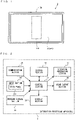
- FIG. 1 is a plan view of an example of the external appearance of the information processing apparatus 3.
- the information processing apparatus 3 includes a display section 35, a sound output section 36, and an actuator 373.
- the display section 35 is provided on the front surface of the main body of the information processing apparatus 3.
- the display section 35 includes an LCD (Liquid Crystal Display) and may employ, for example, a display device using EL.
- the display section 35 may be a display device capable of displaying a stereoscopically viewable image.
- a touch panel 341 which is an example of an input section 34, is provided so as to cover a display screen of the display section 35.
- the touch panel 341 detects the position of an input provided to a predetermined input surface (e.g., the display screen of the display section 35).
- the input section 34 is an input device that allows a user of the information processing apparatus 3 to input an operation, and the input section 34 may be any input device.
- an operation section such as a slide pad, an analog stick, a directional pad, an operation button, or the like may be provided on the side surfaces, the back surface, or the like of the main body of the information processing apparatus 3.
- the input section 34 may be a sensor for detecting the orientation and the motion of the main body of the information processing apparatus 3.
- the input section 34 may be an acceleration sensor for detecting the acceleration generated in the main body of the information processing apparatus 3, an angular velocity sensor (a gyro sensor) for detecting the amount of rotation of the main body of the information processing apparatus 3, or the like.
- the sound output section 36 includes a loudspeaker for outputting a sound, and in the example shown in FIG. 1 , includes a loudspeaker provided on the upper side surface or the back surface of the information processing apparatus 3.
- the sound output section 36 performs D/A conversion on a sound signal (a sound control signal) output from a control section 31 described later, thereby generating an analog sound signal. Then, the sound output section 36 outputs the analog sound signal to the loudspeaker, thereby outputting a sound.
- the actuator 373 is a vibration actuator (a vibrator) for imparting a predetermined vibration to the main body of the information processing apparatus 3 and is included in a vibration generation section 37 described later.
- the actuator 373 is provided near the center of the inside of the main body of the information processing apparatus 3.
- the actuator 373 is provided in a central portion of the display section 35, which is a position between the left hand and the right hand of the user when holding a left end portion of the information processing apparatus 3 in the left hand and holding a right end portion of the information processing apparatus 3 in the right hand.
- the vibration generation section 37 performs D/A conversion on a vibration control signal output from the control section 31 described later, thereby generating an analog vibration signal. Then, the vibration generation section 37 outputs a driving signal obtained by amplifying the analog vibration signal to the actuator 373, thereby driving the actuator 373.
- the display screen of the display section 35 and the sound output section 36 which are provided in the information processing apparatus 3, are placed at positions close to each other.
- the display screen of the display section 35 and the actuator 373 are placed at positions close to each other.
- the sound output section 36 and the actuator 373 are placed at positions close to each other, but are different units disposed at different positions. Consequently, it is possible to include a unit dedicated to outputting a vibration and a unit dedicated to outputting a sound. Thus, it is possible to output a vibration and a sound more accurately than when a general-purpose unit is shared.
- a module into which a unit for outputting a vibration and a unit for outputting a sound are combined and integrated may be provided in the information processing apparatus 3.
- FIG. 2 is a block diagram showing an example of the configuration of the information processing apparatus 3.
- the information processing apparatus 3 includes the control section 31, a storage section 32, a program storage section 33, and a communication section 38 in addition to the input section 34, the display section 35, the sound output section 36, and the vibration generation section 37, which are described above. It should be noted that the information processing apparatus 3 may be composed of one or more apparatuses including: an information processing apparatus having at least the control section 31; and another apparatus.
- the control section 31 is information processing means (a computer) for performing various types of information processing and is, for example, a CPU.
- the control section 31 has the function of performing, as the various types of information processing, processing or the like corresponding to an operation performed on the input section 34 by the user.
- the functions of the control section 31 are achieved by, for example, the CPU executing a predetermined program.
- the control section 31 controls the display of an image to be displayed on the display section 35. Further, as the various types of information processing, the control section 31 outputs, to the sound output section 36, a sound control signal (e.g., a digital sound signal) for controlling a sound to be output from the loudspeaker. Further, as an example of the various types of information processing, the control section 31 receives vibration data transferred from another apparatus via the communication section 38, generates, based on the vibration data, a vibration control signal (e.g., a digital vibration signal) for controlling the vibration to be generated by the actuator 373, and outputs the vibration control signal to the vibration generation section 37.
- a vibration control signal e.g., a digital vibration signal
- the storage section 32 stores various data to be used when the control section 31 performs the above information processing.
- the storage section 32 is, for example, a memory accessible by the CPU (the control section 31).
- the program storage section 33 stores a program.
- the program storage section 33 may be any storage device (storage medium) accessible by the control section 31.
- the program storage section 33 may be a storage device provided in the information processing apparatus 3 having the control section 31, or may be a storage medium detachably attached to the information processing apparatus 3 having the control section 31.
- the program storage section 33 may be a storage device (a server or the like) connected to the control section 31 via a network.
- the control section 31 (the CPU) may read a part or all of a game program or the vibration signal generation program to the storage section 32 at appropriate timing and execute the read program.
- the communication section 38 is composed of a predetermined communication module.
- the communication section 36 transmits and receives data to and from another device via the network, and directly transmits and receives data to and from another information processing apparatus 3. It should be noted that the communication section 38 may transmit and receive data to and from another device by wireless communication, or may transmit and receive data to and from another device by wired communication.
- FIG. 3 is a block diagram showing an example of the configuration of the vibration generation section 37.
- the vibration generation section 37 includes a codec section 371, an amplification section 372, the actuator (vibrator) 373.
- the codec section 371 acquires a vibration control signal output from the control section 31 and performs a predetermined decoding process on the vibration control signal, thereby generating an analog vibration signal. Then, the codec section 371 outputs the analog vibration signal to the amplification section 372. For example, to generate a vibration in the actuator 373, the control section 31 outputs a vibration control signal (e.g., a vibration control signal CS) for controlling the vibration to be generated. In this case, the codec section 371 decodes the vibration control signal output from the control section 31, thereby generating an analog vibration signal (e.g., an analog vibration signal AS) for generating a vibration in the actuator 373. Then, the codec section 371 outputs the analog vibration signal to the amplification section 372.
- a vibration control signal e.g., a vibration control signal CS
- the amplification section 372 amplifies the analog vibration signal output from the codec section 371, thereby generating a driving signal for driving the actuator 373. Then, the amplification section 372 outputs the driving signal to the actuator 373. For example, the amplification section 372 increases changes in the amplitudes of the current and/or the voltage of the analog vibration signal (e.g., the analog vibration signal AS) output from the codec section 371, thereby generating a driving signal (e.g., a driving signal DS). Then, the amplification section 372 outputs the driving signal to the actuator 373.
- the analog vibration signal e.g., the analog vibration signal AS
- a driving signal e.g., a driving signal DS
- the actuator 373 is driven in accordance with the driving signal output from the amplification section 372, thereby imparting a vibration corresponding to the driving signal to the main body of the information processing apparatus 3.
- the actuator 373 is provided in the center of the display screen of the display section 35.
- the method of the actuator 373 imparting a vibration to the main body of the information processing apparatus 3 may be any method.
- the actuator 373 may use the method of generating a vibration by an eccentric motor (ERM: Eccentric Rotating Mass), the method of generating a vibration by a linear vibrator (LRA: Linear Resonant Actuator), the method of generating a vibration by a piezoelectric element, or the like. If the driving signal to be output from the amplification section 372 is generated in accordance with the method of the actuator 373 generating a vibration, an actuator using any method can impart various vibrations to the user of the information processing apparatus 3.
- EPM Eccentric Rotating Mass
- LRA Linear Resonant Actuator
- a driving signal for driving the actuator 373 is generated by amplifying the analog vibration signal generated by the codec section 371.
- the signal output from the codec section 371 to the amplification section 372 may be a digital signal.
- the codec section 371 may generate a pulse signal for turning on and off the actuator 373.
- the signal output from the codec section 371 to the amplification section 372 is a digital vibration signal for controlling the driving of the actuator 373 using pulse waves. Consequently, the amplification section 372 amplifies the digital vibration signal.
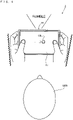
- FIG. 4 is a diagram showing an example where the main body of the information processing apparatus 3 vibrates and simultaneously, a sound is output when a virtual object OBJ displayed on the display screen of the display section 35 moves.
- FIG. 5 is a diagram illustrating an example of the process of generating a vibration control signal based on acquired vibration data.
- FIG. 6 is a diagram illustrating an example of the process of generating a vibration control signal based on vibration data acquired with respect to each frequency range.
- a virtual object OBJ moving in a virtual space is displayed on the display screen of the display section 35.
- the virtual object OBJ is displayed on the display screen of the display section 35 so as to move in the virtual space in accordance with a user operation or automatically.
- the virtual object OBJ is a sphere that moves while rolling on a board surface installed in the virtual space.
- the information processing apparatus 3 outputs a sound, and simultaneously, the main body of the information processing apparatus 3 vibrates.
- the loudspeaker (the sound output section 36) provided in the main body of the information processing apparatus 3 outputs a sound such that the virtual object OBJ displayed on the display screen of the display section 35 is the sound source.
- the actuator 373 provided in the main body of the information processing apparatus 3 generates the vibration to occur when the virtual object OBJ moves while rolling.
- vibration data for generating a vibration control signal for generating this vibration is acquired from another apparatus. Then, based on the acquired vibration data, the information processing apparatus 3 generates a vibration control signal for controlling the driving of the actuator 373.
- a vibration control signal for controlling the vibration to be generated by the actuator 373 is generated based on vibration data transferred from another apparatus.
- AM/FM code data transferred from another apparatus is received as vibration data
- an AM/FM wave generated based on the AM/FM code data is used as a vibration control signal.
- AM code data indicates data representing the amplitude modulation of the vibration
- FM code data indicates data representing the frequency modulation of the vibration.
- AM/FM code data indicates data representing both the amplitude modulation and the frequency modulation of the vibration.
- an AM/FM wave indicates a vibration waveform amplitude-modulated and frequency-modulated based on the AM/FM code data.
- the AM/FM code data is transferred from another apparatus in each constant update cycle of modulating the vibration and functions as the amplitude of the vibration/frequency update command. Then, the AM/FM code data is decoded using a predetermined encoding table, thereby retrieving AM information and FM information.
- the AM information is information indicating the amplitude of the vibration after the update, based on the vibration before the update.
- Such AM information is analyzed in each update cycle described above, whereby it is possible to acquire information as shown in FIG. 5 for modulating the amplitude of the vibration in a time-series manner based on a predetermined amplitude.
- the FM information is information indicating the frequency of the vibration after the update, based on the frequency of the vibration before the update.
- Such FM information is analyzed in each update cycle described above, whereby it is possible to acquire information as shown in FIG. 5 for modulating the frequency of the vibration in a time-series manner based on a predetermined frequency. It should be noted that examples of the decoding process of the AM/FM code data and the encoding table for use in the decoding will be described later.
- a frequency-modulated sine wave (an FM wave) is generated from the FM information.
- the FM wave is a sine wave as shown in FIG. 5 that is displaced with a frequency corresponding to the FM information acquired in each update cycle described above.
- the FM wave is multiplied by the AM information, thereby generating an AM/FM wave.
- the AM/FM wave has a waveform as shown in FIG. 5 that is displaced with a frequency corresponding to the FM information acquired in each update cycle described above, and also with an amplitude corresponding to the AM information acquired in each update cycle described above.
- a vibration control signal is generated based on the thus generated AM/FM wave, whereby it is possible to vibrate the actuator 373 with a frequency and an amplitude indicated by the AM/FM wave.
- Vibration data is transmitted by such an AM/FM transmission method, whereby it is possible to expect the following effects.
- a first effect it is possible to reduce the amount of data communication for transmitting vibration data as compared to a method for transmitting vibration data as it is, a method for transmitting vibration data by lowering the sampling rate of the vibration data, and a method for transmitting vibration data by compressing the vibration data by a predetermined method.
- the processing load for decoding the transmitted AM/FM code data is relatively low, and therefore, it is possible to perform the decoding process in real time and lead to controlling the vibration of the actuator 373.
- parameters for controlling the vibration are the frequency and the amplitude, and therefore, it is possible to simplify the work of generating a vibration material.
- the frequency of the vibration controlled by the AM/FM transmission method is set near the resonance frequency of the actuator 373, whereby it is possible to impart a relatively strong (power-efficient) vibration to the user.
- the AM/FM code data may be transmitted with respect to each frequency range.
- FIG. 6 a description is given below of the process of generating a vibration control signal based on vibration data acquired with respect to each frequency range.
- the AM/FM code data according to the exemplary embodiment is transferred from another apparatus with respect to each frequency range in a constant update cycle of modulating the vibration and functions as a vibration amplitude/frequency update command with respect to each frequency range.
- AM/FM code data targeted for a frequency range A which is a low-frequency range
- AM/FM code data targeted for a frequency range B which is a high-frequency range
- the AM/FM code data targeted for the frequency range A is decoded using the predetermined encoding table similarly to the above process, thereby retrieving AM information and FM information and generating an FM wave from the FM information. Then, the FM wave is multiplied by the AM information targeted for the frequency range A, thereby generating an AM/FM wave targeted for the frequency range A.
- the AM/FM code data targeted for the frequency range B is also decoded using the predetermined encoding table similarly to the above process, thereby retrieving AM information and FM information and generating an FM wave from the FM information. Then, the FM wave is multiplied by the AM information targeted for the frequency range B, thereby generating an AM/FM wave targeted for the frequency range B.
- the AM/FM wave targeted for the frequency range A and the AM/FM wave targeted for the frequency range B are summed up, thereby generating a combined wave.
- the combined wave has both the AM/FM information targeted for the frequency range A and the AM/FM information targeted for the frequency range B and therefore has a waveform as shown in FIG. 6 that is displaced based on information of the frequency and information of the amplitude for a plurality of frequency ranges.
- a vibration control signal is generated based on the thus generated combined wave, whereby it is possible to vibrate the actuator 373 with a frequency and an amplitude indicated by the combined wave.
- Vibration data is transmitted by the AM/FM transmission method with respect to each of such a plurality of frequency ranges, whereby it is possible to transfer a change in the frequency and a change in the amplitude with respect to each of the plurality of frequency ranges.
- Vibration data is transmitted by the AM/FM transmission method with respect to each of such a plurality of frequency ranges, whereby it is possible to transfer a change in the frequency and a change in the amplitude with respect to each of the plurality of frequency ranges.
- Vibration data is transmitted by the AM/FM transmission method with respect to each of such a plurality of frequency ranges, whereby it is possible to transfer a change in the frequency and a change in the amplitude with respect to each of the plurality of frequency ranges.
- it is possible to transmit the vibration from another apparatus more accurately.
- vibration data without causing the deterioration of vibrating sensation to be imparted to the user as compared to another transmission method.
- the plurality of frequency ranges for which the AM/FM code data is transferred can be set in accordance with the characteristics of the tactile sensation of a human being to which the vibration is to be imparted.
- the human sensory receptors for receiving cutaneous sensation include Merkel discs, Meissner corpuscles, Pacinian corpuscles, Ruffini endings, and the like, each of which responds to a vibration in a particular frequency range.
- a vibration that a human being can feel is said to be a vibration in the frequency range of 0 to 1000 Hz.
- the Meissner corpuscles and the Pacinian corpuscles can solely generate vibrating sensation.
- the Meissner corpuscles respond to a low-frequency vibration (e.g., 10 to 200 Hz), and the Pacinian corpuscles respond to a high-frequency vibration (e.g., 70 to 1000 Hz).
- the AM/FM code data can be transferred for each of a low-frequency range (10 to 200 Hz) targeted for the Meissner corpuscles, and a high-frequency range (70 to 1000 Hz) targeted for the Pacinian corpuscles.
- a frequency as a reference with respect to each frequency range (hereinafter referred to as a "center frequency") is set so that, for example, the ratio of the center frequency is 1.5 or more, and is also set to fit the frequency characteristics (e.g., near the resonance frequency) of a vibration device (the actuator 373 in the above exemplary embodiment).
- a frequency band in which the vibration device is likely to vibrate is mainly used, whereby the amount of sense of the vibration to be felt by the user is large relative to power consumed when the vibration is generated. Thus, it is possible to cause the user to feel the vibration more efficiently.
- the vibration device has ideal frequency characteristics (flat characteristics), only the characteristics of the human sensory receptors described above need to be taken into account.
- the center frequency may be set near 40 Hz in a low-frequency range, and may be set near 250 Hz in a high-frequency range.
- a frequency range for which the AM/FM code data is transferred is divided in accordance with the response frequency ranges of the human sensory receptors for receiving cutaneous sensation.
- the frequency range may be divided based on other characteristics.
- a frequency range for which the AM/FM code data is transferred may be divided in accordance with the characteristic frequency of an actuator to be vibrated.
- the actuator to be vibrated has a plurality of resonance frequencies
- a plurality of frequency ranges may be set to include at least one of the resonance frequencies, and the AM/FM code data may be transferred with respect to each of the frequency ranges.
- the AM/FM code data may be transferred with respect to each of three or more frequency ranges.
- the update cycle may not catch up with the speed of transition of frequencies.
- vibrations having three frequencies of 50 Hz, 150 Hz, and 450 Hz are to be generated in order at 50-millisecond intervals, the AM/FM code data is transferred with respect to each of three or more frequency ranges, whereby it is possible to generate accurate vibrations.
- the number of frequency ranges may be two. If, however, a vibration is to be felt by adding an auditory stimulus to the tactile sensation, it can be effective to perform control such that the number of frequency ranges is three or more.
- the ratio between the frequencies should be a simple integer ratio. As described above, the ratio between frequencies to be generated is an integer ratio, whereby it is possible to prevent the generation of a "hum" when vibrations with two frequencies are simultaneously generated.
- a "hum” is the phenomenon that two vibration waves having slightly different vibration frequencies interfere with each other to generate a combined wave of which the amplitude of the vibration slowly and cyclically changes.
- the AM/FM code data may be transferred for a single frequency range.
- the AM/FM code data can be transferred only for a single frequency range.
- the AM/FM code data can be transferred for the frequency range.
- the AM/FM code data can be transferred only for a single frequency range.
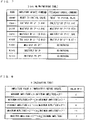
- FIG. 7 is a diagram showing an example of the encoding table used to decode the AM/FM code data.
- FIG. 8 is a diagram showing an example of a k-calculation table used to calculate a value k used in the encoding table.
- FIG. 7 shows a 3-bit AM/FM encoding table for executing an amplitude update command and a frequency update command using a 3-bit code.
- an amplitude value and a frequency to be set next are set based on an amplitude value and a frequency indicated immediately before the update process, using such an AM/FM encoding table, and combined waveform data is calculated at a predetermined sampling rate (e.g., 8000 Hz).
- a predetermined sampling rate e.g., 8000 Hz.
- the sampling rate may be set taking into account the balance between the frequency of update of the AM/FM code data described later and the reproduction accuracy of a required combined waveform, and the like.
- the initial value of the amplitude of the vibration is 1/4096, the minimum value of the amplitude of the vibration is 1/4096, the maximum value of the amplitude of the vibration is 1, and a zero threshold for determining the amplitude of the vibration as 0 is 1.5/4096.
- the initial value of the frequency of the vibration is the center frequency set with respect to each frequency range (e.g., near 160 Hz or 320 Hz, which is the resonance frequency of the vibration device), the minimum value of the frequency of the vibration is 100 Hz, and the maximum value of the frequency of the vibration is 1000 Hz.
- the amplitude update command and the frequency update command shown in FIG. 7 indicate the amplitude value and the frequency to be set next based on the amplitude value and the frequency indicated immediately before the update process. Then, an apparatus having received the amplitude update command and the frequency update command updates and sets, based on the received amplitude update command and frequency update command, the amplitude value of the vibration and the frequency of the vibration in the period until the amplitude update command and the frequency update command are received next.
- the amplitude value of the vibration and the frequency of the vibration to be set based on the received amplitude update command and frequency update command may be set as values immediately after the reception, and the amplitude value of the vibration and the frequency of the vibration may be immediately updated.
- the amplitude value of the vibration and the frequency of the vibration to be set based on the received amplitude update command and frequency update command may be set as values immediately before the amplitude update command and the frequency update command are received next, and the amplitude value of the vibration and the frequency of the vibration may be updated in a gradually increasing manner and/or in a gradually decreasing manner so as to reach the values in the above period.
- the amplitude value of the vibration and the frequency of the vibration to be set based on the received amplitude update command and frequency update command may be set as values in the middle of the period until the amplitude update command and the frequency update command are received next, and the amplitude value of the vibration and the frequency of the vibration may be updated in a gradually increasing manner and/or in a gradually decreasing manner so as to reach the values at a time in the middle of the above period.
- the amplitude value of the vibration is reset to the initial value (e.g., 1/4096) and updated, and the frequency of the vibration is reset to the initial value (e.g., 160 or 320) and updated.
- the AM/FM code data indicates a code 1 (001)
- the amplitude value of the vibration is multiplied by 2 0.5 (approximately 1.414) and updated, and the frequency of the vibration is multiplied by 2 0.2 (approximately 1.149) and updated.
- the amplitude value of the vibration is multiplied by 2 0.5 (approximately 1.414) and updated, and the frequency of the vibration is multiplied by 2 -0.2 (approximately 0.871) and updated.
- the AM/FM code data indicates a code 3 (011)
- the amplitude value of the vibration is multiplied by 2 -0.3 (approximately 0.812) and updated, and the frequency of the vibration is multiplied by 2 0.2 (approximately 1.149) and updated.
- the AM/FM code data indicates a code 4 (100), the amplitude value of the vibration is multiplied by 2 -0.3 (approximately 0.812) and updated, and the frequency of the vibration is multiplied by 2 -0.2 (approximately 0.871) and updated. If the AM/FM code data indicates a code 5 (101), the amplitude value of the vibration is multiplied by 2 k-2 and updated, and the frequency of the vibration is constant. If the AM/FM code data indicates a code 6 (110), the amplitude value of the vibration is multiplied by 2 k and updated, and the frequency of the vibration is constant. If the AM/FM code data indicates a code 7 (111), the amplitude value of the vibration is multiplied by 2 k+2 and updated, and the frequency of the vibration is constant.
- the minimum amplitude e.g. 1/4096
- the decoding process may be performed by another method.
- a decoding process using a 4-bit AM/FM encoding table for executing an amplitude update command and a frequency update command using a 4-bit code or a decoding process using a 2-bit AM encoding table for executing an amplitude update command using a 2-bit code, or a decoding process using a 3-bit AM encoding table for executing an amplitude update command using a 3-bit code, or the like can be used.
- the decoding process using the 4-bit AM/FM encoding table it is possible to execute 15 types of amplitude update commands and 15 types of frequency update commands.
- the decoding process using the 3-bit AM encoding table and the decoding process using the 2-bit AM encoding table it is possible to execute only an amplitude update command.
- the decoding process is performed by modulating the amplitude of a constant and simple sine wave such that the frequency of the vibration is a predetermined frequency (e.g., the center frequency and also a frequency near the substantial resonance frequency of the actuator).
- the vibration is controlled based only on the amplitude, whereby it is possible to control an amplitude update command in detail and also reduce the amount of data communication.
- a fundamental wave used in the decoding process using the 3-bit AM encoding table or the decoding process using the 2-bit AM encoding table may not need to be a simple sine wave of which the frequency is constant, and may be a fundamental wave having a waveform having a shape in which positive and negative values are repeated, such as a rectangular wave, a triangular wave, or a sawtooth wave, or a fundamental wave having a waveform having another shape in which the amplitude is constant.
- noise having a particular frequency range component may be the above fundamental wave.
- the fundamental wave may be formed of white noise passed through a bandpass filter allowing the passage of a particular frequency range component.
- the AM/FM code data to be transferred in the decoding process using the 3-bit AM encoding table or the decoding process using the 2-bit AM encoding table may include information indicating the frequency, the shape, the noise type, and the like of the fundamental wave, and the decoding process may be performed using the fundamental wave based on this information.
- the fundamental wave may be a waveform having a shape in which positive and negative values are not repeated.
- the fundamental wave may only need to be a waveform in which a value greater than a reference value and a value smaller than the reference value are repeated.
- the fundamental wave may be a waveform having a shape in which a positive local maximum and a local minimum equal to or greater than 0 are alternately repeated, or a waveform having a shape in which a local maximum less than or equal to 0 and a negative local minimum are alternately repeated.
- the waveform of the fundamental wave may be a waveform in which a local maximum of+1 and a local minimum of 0 represented by (1 - cos(2 ⁇ ft))/2 are alternately repeated.
- f is the frequency
- t is time. If an FM wave is generated using such a fundamental wave, a waveform is formed in which a local maximum of +1 and a local minimum of 0 are alternately repeated with the frequency indicated by FM information. Then, if an AM/FM wave is generated based on the FM wave, a waveform is formed in which, with a local maximum being an amplitude value between 0 and +1 indicated by AM information, the local maximum and a local minimum of 0 are alternately repeated with the frequency indicated by the FM wave.
- the actuator 373 is composed of a linear vibration motor
- a spring is provided in the linear vibration motor.
- the position of a weight inside the linear vibration motor moves in the direction opposite to that of the force of the spring, and the weight acts in the direction of returning to the previous position by the reaction force of the spring.
- the weight returns to the previous position only by changing the applied voltage to 0 without applying a negative voltage.
- the AM/FM code data may be acquired with a lower frequency of update than in the form in which the AM/FM code data is acquired with respect to a single frequency range, and may be subjected to the decoding process, thereby generating vibration data.
- the AM/FM code data may be acquired from another apparatus in a cycle of 400 Hz in the form in which the AM/FM code data is acquired with respect to a single frequency range and subjected to the decoding process, and is to be subjected to the decoding process
- the AM/FM code data may be acquired from another apparatus in a cycle of 200 Hz in the form in which the AM/FM code data is acquired with respect to each of the two frequency ranges and subjected to the decoding process, and may be subjected to the decoding process.
- the AM/FM code data may be acquired with frequencies of update different between the frequency ranges and subjected to the decoding process.
- the frequency of update for a high-frequency range can be set to be relatively low with respect to the frequency of update for a low-frequency range.
- the AM/FM code data can be transferred with frequencies of update different between the frequency ranges and subjected to the decoding process.
- the AM/FM code data can be acquired from another apparatus with a relatively high frequency of update (e.g., in a cycle of 400 Hz) and subjected to the decoding process.
- the AM/FM code data can be acquired from another apparatus with a relatively low frequency of update (e.g., in a cycle of 200 Hz) and subjected to the decoding process.
- the transfer source apparatus processes the original vibration data using a bandpass filter allowing the passage of a first frequency range component, thereby generating vibration data of the first frequency range component. Then, the transfer source apparatus processes the original vibration data using a bandpass filter allowing the passage of a second frequency range component, thereby generating vibration data of the second frequency range component.
- the transfer source apparatus encodes the general shape of the envelope using a predetermined encoding table, thereby generating AM code data of the first frequency range component. Further, using the envelope waveform of a vibration waveform indicating the vibration data of the second frequency range component, the transfer source apparatus encodes the general shape of the envelope using the above encoding table, thereby generating AM code data of the second frequency range component. Then, the apparatus as the transfer source of AM code data transmits the generated AM code data of the first frequency range component and the generated AM code data of the second frequency range component to another apparatus in each update cycle. It should be noted that the above process of encoding AM code data may be analyzed and prepared in advance in an off-line process by the transfer source apparatus.
- an apparatus having received the AM code data with respect to each frequency range retrieves AM information of the first frequency range component using the above encoding table and multiplies the AM information of the first frequency range component by the fundamental wave of the first frequency range component (e.g., a sine wave of 160 Hz), thereby generating an AM wave corresponding to the first frequency range component. Further, the apparatus retrieves AM information of the second frequency range component using the above encoding table and multiplies the AM information of the second frequency range component by the fundamental wave of the second frequency range component (e.g., a sine wave of 320 Hz), thereby generating an AM wave corresponding to the second frequency range component.
- the fundamental wave of the first frequency range component e.g., a sine wave of 160 Hz
- the apparatus sums up the AM wave corresponding to the first frequency range component and the AM wave corresponding to the second frequency range component to generate a combined wave, thereby generating a vibration control signal for controlling the driving of the actuator based on the combined wave.
- the above process of decoding the AM code data and controlling the vibration of the actuator may be performed in real time in accordance with the acquisition of the AM code data from the transfer source apparatus.
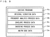
- FIG. 9 is a diagram showing examples of main data and programs stored in a storage section of the transfer source apparatus when the code data transmission process is performed.
- the following are stored in the data storage area of the storage section of the transfer source apparatus: original vibration data Da; frequency analysis process data Db; envelope process data Dc; encoding process data Dd; AM/FM code data De; and the like.
- the storage section of the transfer source apparatus may store, as well as the data shown in FIG. 9 , data and the like necessary for the processing, such as data used in an application to be executed.
- various programs Pa included in a code data transmission program are stored.
- the original vibration data Da is original vibration data (a vibration waveform) prepared in advance in the transfer source apparatus and is vibration data as a source for the process of generating AM/FM code data.
- the frequency analysis process data Db is data representing a frequency included in vibration data obtained by preforming frequency analysis on original vibration data (a vibration waveform).
- the envelope process data Dc is data representing the envelope waveform of a vibration waveform indicating original vibration data or vibration data of a predetermined frequency range component.
- the encoding process data Dd is data used when encoding is performed using AM information (the general shape of an envelope) and/or FM information, and is, for example, data including an encoding table data or the like for use in an encoding process.
- the AM/FM code data De is data representing AM/FM code data obtained by encoding AM information (the general shape of an envelope) and/or FM information.
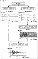
- FIG. 10 is a flow chart showing an example of the code data transmission process performed by the transfer source apparatus.
- a description is given mainly of, in the processing performed by the transfer source apparatus, the process of generating AM/FM code data based on original vibration data and transmitting the AM/FM code data.
- the detailed descriptions of other processes not directly related to these processes are omitted.
- all of the steps performed by a control section of the transfer source apparatus are abbreviated as "S".
- the CPU of the control section of the transfer source apparatus initializes a memory and the like of the storage section of the transfer source apparatus and loads the code data transmission program from the program storage section 33 into the memory. Then, the CPU starts the execution of the code data transmission program. Further, the CPU of the control section 31 also loads the code data transmission program from the transfer source apparatus into the memory. Then, the CPU starts the execution of the code data transmission program.
- the flow chart shown in FIG. 10 is a flow chart showing the processing performed after the above processes are completed.
- the control section of the transfer source apparatus makes transmission settings (step 61), and the processing proceeds to the next step.
- the control section of the transfer source apparatus performs initialization for transmitting AM/FM code data to another apparatus (e.g., the information processing apparatus 3).
- the control section of the transfer source apparatus sets the number of frequency ranges for which AM/FM code data is to be transmitted, the range of each frequency range, the cycle of transmitting the AM/FM code data, an encoding table for use in encoding, and the like in the encoding process data Dd, thereby initializing each parameter.
- control section of the transfer source apparatus acquires, from the storage section of the transfer source apparatus, original vibration data from which to generate AM/FM code data (step 62), and the processing proceeds to the next step.
- control section of the transfer source apparatus extracts, from a plurality of pieces of vibration data stored in advance in the storage section of the transfer source apparatus, vibration data from which to generate AM/FM code data, and stores the extracted vibration data as the original vibration data Da.
- control section of the transfer source apparatus initializes a temporary variable N for use in this process to 1 (step 63), and the processing proceeds to the next step.
- control section of the transfer source apparatus performs a bandpass filter process corresponding to an N-th frequency range (step 64), and the processing proceeds to the next step.
- control section of the transfer source apparatus sets a bandpass filter allowing the passage of an N-th frequency range component and processes the vibration data (the vibration waveform) stored as the original vibration data Da, using the bandpass filter, thereby generating vibration data obtained by removing frequency range components other than the N-th frequency range component.
- control section of the transfer source apparatus performs frequency analysis on the vibration data of the N-th frequency range component generated in the above step 64 (step 65), and the processing proceeds to the next step.
- control section of the transfer source apparatus performs frequency analysis on the vibration data of the N-th frequency range component to analyze a change in the frequency of the vibration included in the vibration data, and stores data representing the analysis result as the frequency analysis process data Db.
- the control section of the transfer source apparatus generates FM information of the N-th frequency range component based on the frequency analysis process data Db corresponding to the N-th frequency range component (step 66), and the processing proceeds to the next step.
- the control section of the transfer source apparatus generates FM information indicating a change in the frequency of the vibration data of the N-th frequency range component (e.g., the FM information as shown in FIG. 5 or 6 ) based on the frequency analysis result obtained in the above step 65.
- control section of the transfer source apparatus generates the envelope waveform of the vibration data of the N-th frequency range component generated in the above step 64 (step 67), and the processing proceeds to the next step.
- control section of the transfer source apparatus generates a signal having an envelope of the vibration data (the vibration waveform) of the N-th frequency range component generated in the above step 64 and stores data representing the signal as the envelope process data Dc.
- an envelope of a moving maximum value (a maximum value in each certain moving section) of the vibration data of the N-th frequency range component may be calculated, or an envelope of a section maximum value in each certain section of the vibration data may be calculated, or a curve passing through a local maximum of the amplitude in the vibration data may be calculated.
- the control section of the transfer source apparatus encodes the general shape of the envelope waveform generated in the above step 67 and the FM information, thereby generating AM/FM code data (step 68), and the processing proceeds to the next step. For example, based on the general shape of the envelope waveform generated in the above step 67, the control section of the transfer source apparatus calculates the amount of change in the amplitude of the N-th frequency range component with respect to each cycle of transmitting AM/FM code data. Further, based on the FM information generated in the above step 66, the control section of the transfer source apparatus calculates the amount of change in the frequency of the N-th frequency range component with respect to each cycle of transmitting AM/FM code data.
- the control section of the transfer source apparatus encodes the calculated amount of change in the amplitude and the calculated amount of change in the frequency, thereby generating AM/FM code data corresponding to the N-th frequency range component with respect to each cycle of transmitting AM/FM code data. Then, the control section of the transfer source apparatus stores the AM/FM code data as the AM/FM code data De corresponding to the N-th frequency range component.
- control section of the transfer source apparatus determines whether or not the encoding process of the original vibration data acquired in the above step 62 is completed with respect to each frequency range (step 69). Then, if a frequency range with respect to which the encoding process is not completed remains, the processing proceeds to step 70. If, on the other hand, a frequency range with respect to which the encoding process is not completed does not remain, the processing proceeds to step 71.
- step 70 the control section of the transfer source apparatus adds 1 to the temporary variable N to update the temporary variable N, and the processing proceeds to the above step 64.
- step 71 the control section of the transfer source apparatus transmits to the transfer destination apparatus (e.g., the information processing apparatus 3) the AM/FM code data corresponding to each cycle of transmitting AM/FM code data and ends the processing of the flow chart.
- the transfer destination apparatus e.g., the information processing apparatus 3
- the above process of encoding AM/FM code data may be performed in advance in an off-line process by the transfer source apparatus and stored as the AM/FM code data De, or may be performed in real time in accordance with a request from the transfer destination apparatus.
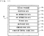
- FIG. 11 is a diagram showing examples of main data and programs stored in the storage section 32 of the information processing apparatus 3 when the code data reception process is performed.
- reception data Dm As shown in FIG. 11 , the following are stored in the data storage area of the storage section 32: reception data Dm; AM information data Dn; FM information data Do; FM wave data Dp; AM/FM wave data Dq; combined wave data Dr; vibration control signal data Ds; and the like.
- the storage section 32 may store, as well as the data shown in FIG. 11 , data and the like necessary for the processing, such as data used in an application to be executed.
- various programs Pb included in a code data reception program are stored.
- the various programs Pb include a reception program for receiving AM/FM code data, a decoding program for decoding AM/FM code data, a vibration control signal generation program for generating a vibration control signal, and the like.
- the reception data Dm is data received from another apparatus (e.g., the above transfer source apparatus).
- the AM information data Dn is data representing AM information retrieved from AM/FM code data transferred from another apparatus.
- the FM information data Do is data representing FM information retrieved from AM/FM code data transferred from another apparatus.
- the FM wave data Dp is data representing a frequency-modulated sine wave (an FM wave) generated from FM information.
- the AM/FM wave data Dq is data representing an AM/FM wave generated by multiplying an FM wave by AM information.
- the combined wave data Dr is data representing a combined wave generated by summing up AM/FM waves generated for respective frequency ranges.
- the vibration control signal data Ds is data, generated based on the combined wave, for controlling the driving of the actuator 373.
- the vibration control signal data Ds is data representing a vibration control signal (the vibration control signal CS; see FIG. 3 ) to be output from the control section 31 to the vibration generation section 37.
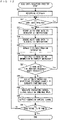
- FIG. 12 is a flow chart showing an example of the code data reception process performed by the information processing apparatus 3.
- a description is given mainly of, in the processing performed by the information processing apparatus 3, the process of receiving AM/FM code data from another apparatus to generate a vibration control signal.
- the detailed descriptions of other processes not directly related to these processes are omitted.
- all of the steps performed by the control section 31 of the information processing apparatus 3 are abbreviated as "S".
- the CPU of the control section 31 of the information processing apparatus 3 initializes a memory and the like of the storage section 32 and loads the code data transmission program from the program storage section 33 of the information processing apparatus 3 into the memory. Then, the CPU starts the execution of the code data reception program.
- the flow chart shown in FIG. 12 is a flow chart showing the processing performed after the above processes are completed.
- the control section 31 makes reception settings (step 81), and the processing proceeds to the next step.
- the control section 31 performs initialization for receiving AM/FM code data from another apparatus (e.g., the above transfer source apparatus).
- the control section 31 sets the number of frequency ranges for which AM/FM code data is to be received, the range of each frequency range, the cycle of receiving the AM/FM code data, an encoding table for use in a decoding process, and the like, thereby initializing each parameter.
- the parameters to be set in the above reception settings may be set based on information described in reception data received from another apparatus.
- control section 31 waits to receive code data (e.g., AM/FM code data) from another apparatus (step 82). Then, if receiving code data from another apparatus, the control section 31 stores the received data as the reception data Dm, and the processing proceeds to step 83.
- code data e.g., AM/FM code data
- step 83 the control section 31 decodes the AM/FM code data received in the above step 82 to retrieve AM information, and the processing proceeds to the next step.
- the control section 31 sets a frequency range as a processing target, extracts AM/FM code data corresponding to the frequency range from the data received in the above step 82, retrieves AM information of the frequency range component based on the set encoding table, and stores the AM information as the AM information data Dn.
- the method for retrieving AM information is similar to the form described above with reference to FIGS. 5 to 8 .
- the AM information is set as the minimum value. Further, if the amplitude value calculated as the AM information is greater than the maximum value (e.g., 1) of the amplitude of the vibration set in advance, the AM information is set as the maximum value.
- the control section 31 decodes the AM/FM code data received in the above step 82 to retrieve FM information (step 84), and the processing proceeds to the next step. For example, the control section 31 extracts, from the data received in the above step 82, AM/FM code data corresponding to a frequency range set as a processing target, retrieves FM information of the frequency range component based on the set encoding table, and stores the FM information as the FM information data Do.
- the method for retrieving FM information is similar to the form described above with reference to FIGS. 5 to 8 . It should be noted that if the frequency calculated as the FM information is smaller than the minimum value (e.g., 100 Hz) of the frequency of the vibration set in advance, the FM information is set as the minimum value. Further, if the frequency calculated as the FM information is greater than the maximum value (e.g., 1000 Hz) of the frequency of the vibration set in advance, the FM information is set as the maximum value.
- the minimum value e.g. 100 Hz
- the FM information is set as
- control section 31 generates a frequency-modulated sine wave (an FM wave) from the FM information retrieved in the above step 84 (step 85), and the processing proceeds to the next step. For example, as described above with reference to FIGS. 5 and 6 , the control section 31 generates, as an FM wave corresponding to the above frequency range, a sine wave that is displaced with a frequency corresponding to the FM information. Then, the control section 31 stores data representing the FM wave as the FM wave data Dp.
- a frequency-modulated sine wave an FM wave
- control section 31 multiplies the FM wave generated in the above step 85 by the AM information retrieved in the above step 83, thereby generating an AM/FM wave (step 86), and the processing proceeds to the next step.
- the control section 31 generates, as an AM/FM wave corresponding to the above frequency range, a vibration waveform that is displaced with an amplitude corresponding to the AM information retrieved in the above step 83 and with a frequency corresponding to the FM wave generated in the above step 85.
- the control section 31 stores data representing the AM/FM wave as the AM/FM wave data Dq.
- the amplitude value of the AM/FM wave may be changed by a multiplying factor necessary for the conversion in the above step 86. For example, if a vibration sample is represented by a 16-bit integer type with a sign (-32768 to +32767) in the application, the amplitude value of the AM/FM wave is multiplied by 32767 for conversion. If the amplitude value of the AM/FM wave is smaller than the zero threshold (e.g., 1.5/4096), the value of the amplitude of the vibration for use in the application is converted to 0.
- the zero threshold e.g. 1.5/4096
- control section 31 determines whether or not code data for another frequency range is received in the above step 82 (step 87). Then, if code data for another frequency range is received, the control section 31 sets a different frequency range as a processing target, and the processing proceeds to the above step 83. If, on the other hand, code data for another frequency range is not received (the decoding process of code data for all the frequency ranges is completed), the control section 31 sets a different frequency range as a processing target, and the processing proceeds to step 83.
- step 88 the control section 31 sums up the AM/FM waves targeted for the respective frequency ranges generated in the above step 86, thereby generating a combined wave, and the processing proceeds to the next step.
- the control section 31 stores, as the combined wave data Dr, data representing a combined wave generated by summing up the AM/FM waves targeted for the frequency ranges.
- the control section 31 generates a vibration control signal (step 89), and the processing proceeds to the next step.
- the control section 31 generates the combined wave generated in the above step 88, as it is as a vibration control signal and stores the vibration control signal in the vibration control signal data Ds.
- control section 31 outputs the vibration control signal (step 90), and the processing proceeds to the next step.
- control section 31 outputs to the vibration generation section 37 the vibration control signal CS indicated by the vibration control signal data Ds. Consequently, the vibration generation section 37 generates a vibration corresponding to the vibration control signal CS from the actuator 373.
- control section 31 determines whether or not the processing is to be ended (step 91). Examples of conditions for ending the processing include: the satisfaction of the condition under which the processing is ended; and the fact that the user performs the operation of ending the processing. If the processing is not to be ended, the control section 31 returns to the above step 8 and repeats the process thereof. If the processing is to be ended, the control section 31 ends the processing indicated by the flow chart.
- a transfer destination apparatus (e.g., the information processing apparatus 3) can generate vibration data using code data transferred from a transfer source apparatus.
- the transfer destination apparatus can also change a vibration parameter (e.g., the frequency of the vibration or the amplitude of the vibration) while vibrating an actuator.
- a vibration parameter e.g., the frequency of the vibration or the amplitude of the vibration
- a vibration signal may be generated in another form.
- code data generated in each predetermined cycle may be stored in advance in an apparatus for generating a vibration signal (the information processing apparatus 3 in the above example), and if a vibration signal based on the code data is needed, the apparatus may acquire and decode the code data stored in the apparatus itself, thereby generating the vibration signal. This makes it possible to reduce, in an apparatus for generating a vibration signal, the amount of data stored for generating the vibration signal.
- a single actuator 373 is provided in the information processing apparatus 3.
- a plurality of actuators for imparting vibrations to the user may be provided.
- a pair of actuators may be provided on the left and right of the information processing apparatus 3.
- the control section 31 may generate vibration control signals for driving the respective actuators from a single piece of code data, or may generate vibration control signals for driving the respective actuators from different pieces of code data (e.g., code data for one of the actuators, and code data for the other actuator).
- the control section 31 outputs a vibration control signal for controlling the vibration of each actuator 373.
- the codec section 371 decodes the vibration control signals output from the control section 31, thereby generating analog vibration signals for generating vibrations in the respective actuators 373. Then, the codec section 371 outputs the vibration control signals to the amplification section 372. Then, the amplification section 372 increases changes in the amplitudes of the current and/or the voltage of each of the analog vibration signals output from the codec section 371, thereby generating driving signals. Then, the amplification section 372 outputs the driving signals to the plurality of actuators 373.
- the actuators can also impart, to the user of the information processing apparatus 3, vibrations for causing the user to perceive the position of a predetermined image displayed on the display section 35, as the vibration source in a pseudo manner.
- a transfer source apparatus for transferring code data wirelessly transmits the code data to the information processing apparatus 3.
- the transfer source apparatus may transmit the code data to the information processing apparatus 3 in a wired manner. Even if the transfer speed of communication in a wireless or wired manner is slow, the sending of code data makes it possible to prevent the delay of vibration control.
- an apparatus as the transfer destination of code data may be an operation apparatus (a so-called controller) held and operated by the user.
- an actuator for generating a vibration is provided in the operation apparatus, and an apparatus as the transfer source of the code data (e.g., the main body of a game apparatus) transfers the code data for generating vibration data to the operation apparatus (e.g., a controller) by wireless communication.
- the operation apparatus decodes the code data and controls the driving of the actuator built into the operation apparatus based on the decoded vibration data.
- the main body of the game apparatus transmits code data to the controller, and the driving of an actuator in the controller is controlled, whereby it is possible to obtain an effect similar to the above.
- the controller wirelessly connected to the main body of the game apparatus may be a plurality of controllers (e.g., a plurality of controllers held by a plurality of users, or a pair of controllers held by a single user with both hands), and the game system may include the main body of the game apparatus and the plurality of controllers into which actuators are built.
- the main body of the game apparatus transfers code data for generating vibration data to each of the plurality of controllers by wireless communication, thereby enabling each controller to generate a vibration corresponding to the code data.
- the main body of the game apparatus may not perform the process of encoding vibration data, and data obtained by encoding vibration data may be included in advance in a program or the like installed in the main body of the game apparatus.
- the main body of the game apparatus outputs code data encoded in advance to the controller, where necessary, and the controller decodes the code data.
- the communication between the main body of the game apparatus and a single controller or a plurality of controllers may be performed in a wireless or wired manner.
- the transfer source apparatus performs the data output process (e.g., the code data transmission process), and the information processing apparatus 3 performs the vibration signal generation process (the code data reception process).
- another apparatus may perform at least some of the processing steps in the processing.
- the transfer source apparatus and the information processing apparatus 3 are further configured to communicate with another apparatus (e.g., another server, another game apparatus, or another mobile terminal), the other apparatus may cooperate to perform the processing steps of the processing.
- Another apparatus may thus perform at least some of the processing steps in the processing, thereby enabling processing similar to the above information processing.
- the above processing can be performed by a processor or the cooperation of a plurality of processors, the processor or the plurality of processors included in an information processing system including at least one information processing apparatus.
- the information processing system including at least one information processing apparatus can be an information processing system including a plurality of information processing apparatuses (a so-called system including a complex of a plurality of apparatuses), or can be an information processing system including a single information processing apparatus (a so-called system including a single apparatus including a plurality of units).
- the processing indicated in the above flow chart is performed by the control section of each of the transfer source apparatus and the information processing apparatus 3 executing a predetermined vibration signal generation program.
- a part or all of the processing indicated in the flow chart may be performed by a dedicated circuit included in each of the transfer source apparatus and the information processing apparatus 3.
- the above variations make it possible to achieve the exemplary embodiment also by a system form such as so-called cloud computing, or a system form such as a distributed wide area network or a local area network.
- a system form such as a distributed local area network
- a stationary information processing apparatus a stationary game apparatus
- a mobile information processing apparatus a mobile game apparatus
- the processing orders, the setting values, the conditions used in the determinations, and the like that are used in the above information processing are merely illustrative.
- the exemplary embodiment can be achieved also with other orders, other values, and other conditions.
- the shapes, the number, the placement positions, the functions, and the like of the components used by the above information processing apparatus are merely illustrative, and may be other shapes, number, and placement positions.
- the exemplary embodiment can be achieved by the information processing apparatus having other functions.
- three or more actuators may impart vibrations to the information processing apparatus, or three or more loudspeakers may output sounds from the information processing apparatus.
- the information processing apparatus may include a plurality of display sections.
- a mobile apparatus e.g., a tablet terminal
- the information processing apparatus 3 may be a handheld apparatus or a portable apparatus larger than a mobile apparatus.
- a handheld apparatus is an apparatus that can be operated by the user holding it in their hands, and is a concept including the above mobile apparatus.
- a portable apparatus is an apparatus that allows the movement of the main body of the apparatus when the apparatus is used, or allows a change in the orientation of the main body of the apparatus when the apparatus is used, or allows the carrying around of the main body of the apparatus, and is a concept including the above handheld apparatus and mobile apparatus.
- the vibration signal generation program may be supplied to the information processing apparatus 3 not only through an external storage medium such as the external memory 45, but also through a wired or wireless communication link. Further, the vibration signal generation program may be stored in advance in a non-volatile storage device included in the information processing apparatus 3. It should be noted that examples of an information storage medium having stored therein the vibration signal generation program may include CD-ROMs, DVDs, optical disk storage media similar to these, flexible disks, hard disks, magneto-optical disks, and magnetic tapes, as well as non-volatile memories. Alternatively, an information storage medium having stored therein the vibration signal generation program may be a volatile memory for storing the vibration signal generation program. It can be said that such a storage medium is a storage medium readable by a computer or the like. For example, it is possible to provide the above various functions by causing a computer or the like to load a game program from the storage medium and execute it.
- the present invention is useful as, for example, a vibration signal generation program, a vibration signal generation system, a vibration signal generation apparatus, a vibration signal generation method, a data output program, and the like in order, for example, to change a vibration parameter.
Landscapes
- Engineering & Computer Science (AREA)
- Multimedia (AREA)
- Human Computer Interaction (AREA)
- Computer Networks & Wireless Communication (AREA)
- Signal Processing (AREA)
- User Interface Of Digital Computer (AREA)
- Apparatuses For Generation Of Mechanical Vibrations (AREA)
Claims (24)
- Un programme de génération de signal de vibration à exécuter par un calculateur (31) inclus dans un appareil (3) pour générer un signal de vibration pour faire vibrer un appareil de vibration (373), le programme de génération de signal de vibration amenant le calculateur à fonctionner en tant que :un moyen d'acquisition de données (31, S82) pour acquérir une première donnée obtenue par le codage d'une information de modulation d'amplitude indiquant un changement d'une amplitude et une deuxième donnée obtenue par le codage d'une information de modulation de fréquence indiquant un changement d'une fréquence ;un moyen de décodage (31, S83) pour décoder les première et deuxième données acquises ; etun moyen de génération de signal de vibration (31, S86) pour générer un signal de vibration en utilisant l'information de modulation d'amplitude décodée et une amplitude du signal de vibration précédemment généré et en utilisant l'information de modulation de fréquence décodée et une fréquence du signal de vibration précédemment généré.
- Le programme de génération de signal de vibration selon la revendication 1, dans lequel
le moyen de génération de signal de vibration génère le signal de vibration en utilisant une donnée de forme d'onde indiquant une forme d'onde prédéterminée dans laquelle une valeur supérieure à une valeur de référence et une valeur inférieure à la valeur de référence sont répétées, et l'information de modulation d'amplitude. - Le programme de génération de signal de vibration selon la revendication 2, dans lequel
dans la forme d'onde prédéterminée, des valeurs positives et négatives sont répétées. - Le programme de génération de signal de vibration selon la revendication 3, dans lequel
dans la forme d'onde prédéterminée, une amplitude est constante. - Le programme de génération de signal de vibration selon la revendication 4, dans lequel
la forme d'onde prédéterminée est une onde sinusoïdale dans laquelle une amplitude est constante. - Le programme de génération de signal de vibration selon la revendication 4, dans lequel
la forme d'onde prédéterminée est une onde rectangulaire dans laquelle une amplitude est constante. - Le programme de génération de signal de vibration selon l'une des revendications 2 à 6, dans lequel
la forme d'onde prédéterminée est une forme d'onde présentant sensiblement la même fréquence qu'une fréquence de résonance de l'appareil de vibration. - Le programme de génération de signal de vibration selon l'une des revendications 1 à 7, dans lequelle moyen d'acquisition de données acquiert, en tant que la première donnée, une donnée obtenue par le codage d'une information de modulation d'amplitude par rapport à chacune de plages de fréquences différentes,le moyen de décodage décode la première donnée acquise par rapport à chaque plage de fréquences, etle moyen de génération de signal de vibration génère le signal de vibration en utilisant l'information de modulation d'amplitude décodée par rapport à chaque plage de fréquences.
- Le programme de génération de signal de vibration selon la revendication 8, dans lequel
le moyen de génération de signal de vibration génère une première forme d'onde de vibration en utilisant une donnée de forme d'onde indiquant une forme d'onde d'une première fréquence et une information de modulation d'amplitude décodée pour une première plage de fréquences, génère une deuxième forme d'onde de vibration en utilisant une donnée de forme d'onde indiquant une forme d'onde d'une deuxième fréquence et une information de modulation d'amplitude décodée pour une deuxième plage de fréquences, et combine la première forme d'onde de vibration et la deuxième forme d'onde de vibration l'une à l'autre, en générant de ce fait le signal de vibration. - Le programme de génération de signal de vibration selon la revendication 8 ou 9, dans lequel
le moyen d'acquisition de données acquiert, en tant que la première donnée, une donnée obtenue par le codage d'une information de modulation d'amplitude par rapport à chaque plage de fréquences comportant au moins l'une de fréquences auxquelles répondent une pluralité de récepteurs sensoriels humains différents pour recevoir une sensation cutanée. - Le programme de génération de signal de vibration selon l'une des revendications 1 à 10, dans lequel
le moyen de génération de signal de vibration change, en utilisant l'information de modulation de fréquence, une fréquence d'une donnée de forme d'onde indiquant une forme d'onde prédéterminée dans laquelle une valeur supérieure à une valeur de référence et une valeur inférieure à la valeur de référence sont répétées, et change, en utilisant l'information de modulation d'amplitude, une amplitude de la forme d'onde prédéterminée, en générant de ce fait le signal de vibration. - Le programme de génération de signal de vibration selon la revendication 11, dans lequel
la forme d'onde prédéterminée est une forme d'onde présentant sensiblement la même fréquence qu'une fréquence de résonance de l'appareil de vibration. - Le programme de génération de signal de vibration selon l'une des revendications 1 à 12, le programme de génération de signal de vibration amenant en outre le calculateur à fonctionner en tant que :
un moyen de contrôle de vibration (31, S90) pour faire vibrer l'appareil de vibration en utilisant le signal de vibration généré par le moyen de génération de signal de vibration. - Le programme de génération de signal de vibration selon l'une des revendications 1 à 13, dans lequel le moyen d'acquisition de données acquiert, auprès d'un autre appareil par communication sans fil, une donnée obtenue par le codage de l'information de modulation d'amplitude.
- Un système de génération de signal de vibration, comportant au moins un premier appareil et un deuxième appareil (3), pour générer un signal de vibration pour faire vibrer un appareil de vibration (373),le premier appareil comprenant :un moyen de stockage pour stocker une première donnée obtenue par le codage d'une information de modulation d'amplitude indiquant un changement d'une amplitude etune deuxième donnée obtenue par le codage d'une information de modulation de fréquence indiquant un changement d'une fréquence dans une forme d'onde de vibration pour faire vibrer l'appareil de vibration ; etun moyen d'émission (S71) pour émettre la première donnée et la deuxième donnée vers le deuxième appareil,le deuxième appareil comprenant :un moyen de réception pour recevoir la première donnée et la deuxième donnée émises depuis le premier appareil ;un moyen de décodage pour décoder les première et deuxième données reçues ; etun moyen de génération de signal de vibration pour générer un signal de vibration en utilisant l'information de modulation d'amplitude décodée et une amplitude du signal de vibration précédemment généré et en utilisant l'information de modulation de fréquence décodée et une fréquence du signal de vibration précédemment généré.
- Un appareil de génération de signal de vibration pour générer un signal de vibration pour faire vibrer un appareil de vibration, l'appareil de génération de signal de vibration comprenant :un moyen d'acquisition de données pour acquérir une première donnée obtenue par le codage d'une information de modulation d'amplitude indiquant un changement d'une amplitude et une deuxième donnée obtenue par le codage d'une information de modulation de fréquence indiquant un changement d'une fréquence ;un moyen de décodage pour décoder les première et deuxième données acquises ; etun moyen de génération de signal de vibration pour générer un signal de vibration en utilisant l'information de modulation d'amplitude décodée et une amplitude du signal de vibration précédemment généré et en utilisant l'information de modulation de fréquence décodée et une fréquence du signal de vibration précédemment généré.
- Un procédé de génération de signal de vibration à exécuter par un processeur ou une coopération d'une pluralité de processeurs, le processeur ou la pluralité de processeurs étant inclus dans un système comportant au moins un appareil pour générer un signal de vibration pour faire vibrer un appareil de vibration, le procédé de génération de signal de vibration comprenant :une étape d'acquisition de données consistant à acquérir une première donnée obtenue par le codage d'une information de modulation d'amplitude indiquant un changement d'une amplitude et une deuxième donnée obtenue par le codage d'une information de modulation de fréquence indiquant un changement d'une fréquence ;une étape de décodage consistant à décoder les première et deuxième données acquises ; etune étape de génération de signal de vibration consistant à générer un signal de vibration en utilisant l'information de modulation d'amplitude décodée et une amplitude du signal de vibration précédemment généré et en utilisant l'information de modulation de fréquence décodée et une fréquence du signal de vibration précédemment généré.
- Un programme de sortie de données à exécuter par un calculateur inclus dans un appareil pour délivrer des données permettant la génération d'un signal de vibration pour faire vibrer un appareil de vibration, le programme de sortie de données amenant le calculateur à fonctionner en tant que :un moyen de définition d'information de modulation d'amplitude pour définir une information de modulation d'amplitude indiquant un changement d'une amplitude dans une forme d'onde de vibration pour faire vibrer l'appareil de vibration et un moyen de définition d'information de modulation de fréquence pour définir une information de modulation de fréquence indiquant un changement d'une fréquence dans la forme d'onde de vibration pour faire vibrer l'appareil de vibration ;un moyen de codage pour coder l'information de modulation d'amplitude pour générer une première donnée et pour coder l'information de modulation de fréquence pour générer une deuxième donnée ; etun moyen de sortie de données pour délivrer la première donnée codée et la deuxième donnée codée.
- Le programme de sortie de données selon la revendication 18, dans lequelle moyen de définition d'information de modulation d'amplitude définit une information de modulation d'amplitude indiquant un changement d'une amplitude en référence à chacune de plages de fréquences différentes pour la forme d'onde de vibration, par rapport à chaque plage de fréquences,le moyen de codage code et génère, en tant que la première donnée, l'information de modulation d'amplitude définie par rapport à chaque plage de fréquences, etle moyen de sortie de données délivre la première donnée générée par rapport à chaque plage de fréquences.
- Le programme de sortie de données selon la revendication 19, dans lequelle moyen de définition d'information de modulation d'amplitude définit l'information de modulation d'amplitude indiquant le changement de l'amplitude dans la forme d'onde de vibration à chaque intervalle de temps prédéterminé, etle moyen de définition d'information de modulation d'amplitude définit, sur la base d'une grandeur de l'amplitude indiquée par rapport à chaque plage de fréquences, l'intervalle de temps par rapport à chaque plage de fréquences.
- Le programme de sortie de données selon la revendication 19 ou 20, dans lequel
le moyen de définition d'information de modulation d'amplitude définit l'information de modulation d'amplitude indiquant un changement d'une amplitude par rapport à chaque plage de fréquences comportant au moins l'une de fréquences auxquelles répondent une pluralité de récepteurs sensoriels humains différents pour recevoir une sensation cutanée, par rapport à chaque plage de fréquences. - Le programme de sortie de données selon la revendication 18, dans lequel
le moyen de définition d'information de modulation de fréquence définit l'information de modulation de fréquence en réalisant une analyse de fréquence prédéterminée sur la forme d'onde de vibration. - Le programme de sortie de données selon l'une des revendications 18 à 22, dans lequel
le moyen de définition d'information de modulation d'amplitude définit l'information de modulation d'amplitude en utilisant une forme d'onde présentant une enveloppe d'une valeur prédéterminée dans la forme d'onde de vibration. - Le programme de sortie de données selon la revendication 23, dans lequelle moyen de définition d'information de modulation d'amplitude définit une information de modulation d'amplitude indiquant un changement d'une amplitude par rapport à chacune de plages de fréquences différentes pour la forme d'onde de vibration, par rapport à chaque plage de fréquences, etle moyen de définition d'information de modulation d'amplitude réalise un processus de filtre passe-bande dans lequel une forme d'onde de vibration de la plage de fréquences passe à travers chaque plage de fréquences, puis définit l'information de modulation d'amplitude par rapport à chaque plage de fréquences en utilisant une forme d'onde présentant l'enveloppe.
Applications Claiming Priority (1)
| Application Number | Priority Date | Filing Date | Title |
|---|---|---|---|
| JP2015086842A JP6445921B2 (ja) | 2015-04-21 | 2015-04-21 | 振動信号生成プログラム、振動信号生成システム、振動信号生成装置、振動信号生成方法、およびデータ出力プログラム |
Publications (2)
| Publication Number | Publication Date |
|---|---|
| EP3088064A1 EP3088064A1 (fr) | 2016-11-02 |
| EP3088064B1 true EP3088064B1 (fr) | 2022-09-21 |
Family
ID=55697013
Family Applications (1)
| Application Number | Title | Priority Date | Filing Date |
|---|---|---|---|
| EP16163513.1A Active EP3088064B1 (fr) | 2015-04-21 | 2016-04-01 | Programme de génération de signaux de vibration, système de génération de signaux de vibration, appareil de génération de signaux de vibration, procédé de génération de signaux de vibration et programme de sortie de données |
Country Status (3)
| Country | Link |
|---|---|
| US (1) | US11167210B2 (fr) |
| EP (1) | EP3088064B1 (fr) |
| JP (1) | JP6445921B2 (fr) |
Families Citing this family (48)
| Publication number | Priority date | Publication date | Assignee | Title |
|---|---|---|---|---|
| JP6332476B2 (ja) * | 2015-01-26 | 2018-05-30 | 富士通株式会社 | 駆動制御装置、電子機器、駆動制御プログラム、及び駆動制御方法 |
| US11676461B2 (en) * | 2016-08-29 | 2023-06-13 | Sony Corporation | Information processing device, information processing method, and program for controlling haptics based on context information |
| US10963054B2 (en) | 2016-12-15 | 2021-03-30 | Sony Interactive Entertainment Inc. | Information processing system, vibration control method and program |
| US10963055B2 (en) * | 2016-12-15 | 2021-03-30 | Sony Interactive Entertainment Inc. | Vibration device and control system for presenting corrected vibration data |
| US10969867B2 (en) | 2016-12-15 | 2021-04-06 | Sony Interactive Entertainment Inc. | Information processing system, controller device, controller device control method and program |
| JP6521460B2 (ja) | 2016-12-28 | 2019-05-29 | 任天堂株式会社 | 情報処理システム、情報処理プログラム、情報処理装置、および、情報処理方法 |
| JP6670258B2 (ja) | 2017-01-10 | 2020-03-18 | 任天堂株式会社 | ゲームシステム、ゲームプログラム、ゲーム装置およびゲーム方法 |
| JP6776132B2 (ja) | 2017-01-10 | 2020-10-28 | 任天堂株式会社 | ゲームシステム、ゲームプログラム、ゲーム装置およびゲーム方法 |
| JP6832712B2 (ja) | 2017-01-13 | 2021-02-24 | 任天堂株式会社 | 振動制御システム、振動制御装置、振動制御プログラムおよび振動制御方法 |
| JP6731376B2 (ja) * | 2017-04-13 | 2020-07-29 | 日本電信電話株式会社 | 空中像投影装置及び空中像投影方法 |
| WO2018193514A1 (fr) | 2017-04-18 | 2018-10-25 | 株式会社ソニー・インタラクティブエンタテインメント | Dispositif de commande de vibration |
| WO2018193513A1 (fr) | 2017-04-18 | 2018-10-25 | 株式会社ソニー・インタラクティブエンタテインメント | Dispositif de commande de vibration |
| US11013990B2 (en) | 2017-04-19 | 2021-05-25 | Sony Interactive Entertainment Inc. | Vibration control apparatus |
| JP6757466B2 (ja) | 2017-04-26 | 2020-09-16 | 株式会社ソニー・インタラクティブエンタテインメント | 振動制御装置 |
| JP6884216B2 (ja) | 2017-08-24 | 2021-06-09 | 株式会社ソニー・インタラクティブエンタテインメント | 振動制御装置 |
| US11779836B2 (en) | 2017-08-24 | 2023-10-10 | Sony Interactive Entertainment Inc. | Vibration control apparatus |
| WO2019043781A1 (fr) | 2017-08-29 | 2019-03-07 | 株式会社ソニー・インタラクティブエンタテインメント | Dispositif de commande de vibration, procédé de commande de vibration et programme |
| CN112313603B (zh) | 2018-06-28 | 2024-05-17 | 索尼公司 | 编码装置、编码方法、解码装置、解码方法和程序 |
| WO2020003727A1 (fr) | 2018-06-28 | 2020-01-02 | ソニー株式会社 | Dispositif de décodage, procédé de décodage et programme |
| US11823557B2 (en) | 2018-07-03 | 2023-11-21 | Sony Corporation | Encoding apparatus, encoding method, decoding apparatus, decoding method, transmission system, receiving apparatus, and program |
| US11482086B2 (en) | 2018-08-10 | 2022-10-25 | Sony Corporation | Drive control device, drive control method, and program |
| CN109508112B (zh) * | 2018-11-23 | 2022-06-17 | 京东方科技集团股份有限公司 | 触控模组及其工作方法、和显示装置 |
| US11594113B2 (en) | 2019-01-17 | 2023-02-28 | Sony Corporation | Decoding device, decoding method, and program |
| WO2020158596A1 (fr) | 2019-02-01 | 2020-08-06 | ソニー株式会社 | Dispositif de décodage, procédé de décodage et programme |
| JP7340983B2 (ja) * | 2019-07-29 | 2023-09-08 | フォルシアクラリオン・エレクトロニクス株式会社 | 振動信号生成装置および振動信号生成用プログラム |
| JP6731531B1 (ja) * | 2019-08-30 | 2020-07-29 | 任天堂株式会社 | 情報処理システム、情報処理プログラム、情報処理方法、および、情報処理装置 |
| DE112020004160T5 (de) | 2019-09-03 | 2022-05-25 | Sony Group Corporation | Steuerungseinrichtung, lautsprechereinrichtung und audioausgabeverfahren |
| DE112020006211T5 (de) | 2019-12-19 | 2022-11-10 | Sony Group Corporation | Steuervorrichtung, Signalverarbeitungsverfahren und Lautsprechervorrichtung |
| CN115209960A (zh) * | 2020-03-04 | 2022-10-18 | 索尼集团公司 | 解码装置、解码方法、程序、编码装置和编码方法 |
| WO2021220659A1 (fr) | 2020-04-29 | 2021-11-04 | ソニーグループ株式会社 | Dispositif de décodage, procédé de décodage, programme, dispositif de codage et procédé de codage |
| CN114125095B (zh) * | 2020-08-31 | 2024-09-10 | 北京小米移动软件有限公司 | 一种终端设备、振动噪音的控制方法、装置及介质 |
| JP7492684B2 (ja) * | 2020-10-07 | 2024-05-30 | 株式会社村田製作所 | 力覚波決定装置、力覚波決定方法及び力覚波決定プログラム |
| WO2022257737A1 (fr) * | 2021-06-10 | 2022-12-15 | 武汉市聚芯微电子有限责任公司 | Procédé et appareil de commande d'effet haptique, et dispositif électronique |
| CN113110748B (zh) * | 2021-06-10 | 2022-06-07 | 武汉市聚芯微电子有限责任公司 | 触觉效果控制方法和装置及电子设备 |
| CN117441150A (zh) | 2021-06-15 | 2024-01-23 | 索尼集团公司 | 触觉信号生成装置、触觉信号生成方法和程序 |
| CN117492570A (zh) * | 2021-07-05 | 2024-02-02 | 腾讯科技(深圳)有限公司 | 触觉振动控制方法、装置、电子设备以及存储介质 |
| CN115703007B (zh) * | 2021-08-12 | 2024-04-12 | 荣耀终端有限公司 | 振动输出方法及相关装置 |
| CN118922803A (zh) * | 2022-03-31 | 2024-11-08 | 索尼集团公司 | 解码设备、解码方法和解码程序 |
| CN115047971B (zh) * | 2022-06-16 | 2023-02-14 | 腾讯科技(深圳)有限公司 | 振动编码处理方法、装置、计算机设备及存储介质 |
| CN117234330A (zh) * | 2023-08-25 | 2023-12-15 | 歌尔股份有限公司 | 一种马达驱动方法及处理装置 |
| EP4580036A1 (fr) | 2023-12-28 | 2025-07-02 | Nintendo Co., Ltd. | Système, programme et procédé d'estimation de température |
| US20250213967A1 (en) | 2023-12-28 | 2025-07-03 | Nintendo Co., Ltd. | System, non-transitory computer-readable storage medium, information processing method, and calibration method |
| US20250213971A1 (en) | 2023-12-28 | 2025-07-03 | Nintendo Co., Ltd. | Vibration control system, non-transitory computer-readable storage media, method, and game controller |
| US20250213969A1 (en) | 2023-12-28 | 2025-07-03 | Nintendo Co., Ltd. | Vibration control system, non-transitory computer-readable storage media, and method |
| US20250213970A1 (en) | 2023-12-28 | 2025-07-03 | Nintendo Co., Ltd. | Vibration control system, non-transitory computer-readable storage media, and method |
| EP4580038A1 (fr) | 2023-12-28 | 2025-07-02 | Nintendo Co., Ltd. | Système d'estimation de température, système de commande, programme et procédé |
| JP2026006871A (ja) | 2024-07-01 | 2026-01-16 | 任天堂株式会社 | 情報処理システム、符号化装置、復号化装置、方法、符号化プログラム、および、復号化プログラム |
| CN121150820B (zh) * | 2025-11-19 | 2026-01-23 | 高勘(广州)技术有限公司 | 光传感通信的上行通信方法、系统、电子设备及存储介质 |
Family Cites Families (12)
| Publication number | Priority date | Publication date | Assignee | Title |
|---|---|---|---|---|
| JPS5717027A (en) * | 1980-07-03 | 1982-01-28 | Hitachi Ltd | Vibration reducing device of electric machinery |
| KR100371456B1 (ko) * | 1995-10-09 | 2004-03-30 | 닌텐도가부시키가이샤 | 삼차원화상처리시스템 |
| AU7725600A (en) | 1999-09-28 | 2001-04-30 | Immersion Corporation | Controlling haptic sensations for vibrotactile feedback interface devices |
| JP4473685B2 (ja) | 2004-09-01 | 2010-06-02 | 任天堂株式会社 | ゲーム装置およびゲームプログラム |
| JP2006163579A (ja) * | 2004-12-03 | 2006-06-22 | Sony Corp | 情報処理システム、情報処理装置及び情報処理方法 |
| JP5025721B2 (ja) * | 2006-04-06 | 2012-09-12 | イマージョン コーポレイション | 触覚効果強化のためのシステムおよび方法 |
| US20080311990A1 (en) * | 2007-06-13 | 2008-12-18 | Cheng Uei Precision Industry Co., Ltd. | Position system for interactive gaming device and method using the same |
| US9174122B2 (en) * | 2007-07-09 | 2015-11-03 | Sony Corporation | Game controller |
| JP2010185714A (ja) * | 2009-02-10 | 2010-08-26 | Panasonic Corp | 物理量センサシステム、物理量センサ装置 |
| EP2823377A4 (fr) | 2012-03-06 | 2016-01-06 | Coactive Drive Corp | Ensemble synchronisé d'actionneurs à vibration dans une topologie de réseau |
| JP2015060274A (ja) * | 2013-09-17 | 2015-03-30 | 日本電信電話株式会社 | 振動提示装置 |
| US9600083B2 (en) * | 2014-07-15 | 2017-03-21 | Immersion Corporation | Systems and methods to generate haptic feedback for skin-mediated interactions |
-
2015
- 2015-04-21 JP JP2015086842A patent/JP6445921B2/ja active Active
-
2016
- 2016-03-30 US US15/084,747 patent/US11167210B2/en active Active
- 2016-04-01 EP EP16163513.1A patent/EP3088064B1/fr active Active
Also Published As
| Publication number | Publication date |
|---|---|
| EP3088064A1 (fr) | 2016-11-02 |
| US20160310844A1 (en) | 2016-10-27 |
| JP2016202486A (ja) | 2016-12-08 |
| US11167210B2 (en) | 2021-11-09 |
| JP6445921B2 (ja) | 2018-12-26 |
Similar Documents
| Publication | Publication Date | Title |
|---|---|---|
| EP3088064B1 (fr) | Programme de génération de signaux de vibration, système de génération de signaux de vibration, appareil de génération de signaux de vibration, procédé de génération de signaux de vibration et programme de sortie de données | |
| US10286310B2 (en) | Information processing apparatus, storage medium having stored therein information processing program, information processing system, and information processing method | |
| US10319199B2 (en) | Vibration generation system, vibration generation apparatus, storage medium having stored therein vibration signal generation program, and vibration generation method | |
| US10062247B2 (en) | Vibration generation system, storage medium having stored therein vibration generation program, and vibration generation method | |
| US9901819B2 (en) | Storage medium having stored therein vibration signal generation program, vibration generation apparatus, vibration generation system, and vibration signal generation method | |
| US10135412B2 (en) | Information processing apparatus, storage medium having stored therein information processing program, information processing system, and information processing method | |
| EP2942089B1 (fr) | Programme de traitement d'informations, appareil de traitement d'informations, système de traitement d'informations et procédé de traitement d'informations | |
| US10796540B2 (en) | Information processing system, information processing apparatus, storage medium having stored therein information processing program, and information processing method | |
| US10983490B2 (en) | Vibration control system, method and apparatus with game controller | |
| JP6721664B2 (ja) | データ出力プログラム、データ出力装置、およびデータ出力方法 | |
| KR101278293B1 (ko) | 복수의 액추에이터를 가상 물체의 속도에 따라 주파수를 변화시키며 순차 구동하되 감지되는 진동 자극의 위치가 연속적으로 변하는 영역을 생성하며 이동 진동파를 구현하는 이동 진동파 생성 방법 | |
| EP3231492B1 (fr) | Système de régulation de vibration, appareil de sortie de vibrations, programme de sortie de vibration et procédé de sortie de vibration | |
| KR101285416B1 (ko) | 복수의 액추에이터를 가상 물체의 속도에 따라 주파수를 변화시키며 순차적으로 구동시켜 이동 진동파를 구현하는 이동 진동파 생성 방법 |
Legal Events
| Date | Code | Title | Description |
|---|---|---|---|
| PUAI | Public reference made under article 153(3) epc to a published international application that has entered the european phase |
Free format text: ORIGINAL CODE: 0009012 |
|
| AK | Designated contracting states |
Kind code of ref document: A1 Designated state(s): AL AT BE BG CH CY CZ DE DK EE ES FI FR GB GR HR HU IE IS IT LI LT LU LV MC MK MT NL NO PL PT RO RS SE SI SK SM TR |
|
| AX | Request for extension of the european patent |
Extension state: BA ME |
|
| 17P | Request for examination filed |
Effective date: 20170428 |
|
| RBV | Designated contracting states (corrected) |
Designated state(s): AL AT BE BG CH CY CZ DE DK EE ES FI FR GB GR HR HU IE IS IT LI LT LU LV MC MK MT NL NO PL PT RO RS SE SI SK SM TR |
|
| STAA | Information on the status of an ep patent application or granted ep patent |
Free format text: STATUS: REQUEST FOR EXAMINATION WAS MADE |
|
| STAA | Information on the status of an ep patent application or granted ep patent |
Free format text: STATUS: EXAMINATION IS IN PROGRESS |
|
| 17Q | First examination report despatched |
Effective date: 20190423 |
|
| GRAP | Despatch of communication of intention to grant a patent |
Free format text: ORIGINAL CODE: EPIDOSNIGR1 |
|
| STAA | Information on the status of an ep patent application or granted ep patent |
Free format text: STATUS: GRANT OF PATENT IS INTENDED |
|
| GRAS | Grant fee paid |
Free format text: ORIGINAL CODE: EPIDOSNIGR3 |
|
| INTG | Intention to grant announced |
Effective date: 20220721 |
|
| GRAA | (expected) grant |
Free format text: ORIGINAL CODE: 0009210 |
|
| STAA | Information on the status of an ep patent application or granted ep patent |
Free format text: STATUS: THE PATENT HAS BEEN GRANTED |
|
| AK | Designated contracting states |
Kind code of ref document: B1 Designated state(s): AL AT BE BG CH CY CZ DE DK EE ES FI FR GB GR HR HU IE IS IT LI LT LU LV MC MK MT NL NO PL PT RO RS SE SI SK SM TR |
|
| RAP3 | Party data changed (applicant data changed or rights of an application transferred) |
Owner name: NINTENDO CO., LTD. |
|
| REG | Reference to a national code |
Ref country code: GB Ref legal event code: FG4D |
|
| REG | Reference to a national code |
Ref country code: CH Ref legal event code: EP |
|
| REG | Reference to a national code |
Ref country code: IE Ref legal event code: FG4D |
|
| REG | Reference to a national code |
Ref country code: DE Ref legal event code: R096 Ref document number: 602016075112 Country of ref document: DE |
|
| REG | Reference to a national code |
Ref country code: AT Ref legal event code: REF Ref document number: 1519678 Country of ref document: AT Kind code of ref document: T Effective date: 20221015 |
|
| REG | Reference to a national code |
Ref country code: LT Ref legal event code: MG9D |
|
| REG | Reference to a national code |
Ref country code: NL Ref legal event code: MP Effective date: 20220921 |
|
| PG25 | Lapsed in a contracting state [announced via postgrant information from national office to epo] |
Ref country code: SE Free format text: LAPSE BECAUSE OF FAILURE TO SUBMIT A TRANSLATION OF THE DESCRIPTION OR TO PAY THE FEE WITHIN THE PRESCRIBED TIME-LIMIT Effective date: 20220921 Ref country code: RS Free format text: LAPSE BECAUSE OF FAILURE TO SUBMIT A TRANSLATION OF THE DESCRIPTION OR TO PAY THE FEE WITHIN THE PRESCRIBED TIME-LIMIT Effective date: 20220921 Ref country code: NO Free format text: LAPSE BECAUSE OF FAILURE TO SUBMIT A TRANSLATION OF THE DESCRIPTION OR TO PAY THE FEE WITHIN THE PRESCRIBED TIME-LIMIT Effective date: 20221221 Ref country code: LV Free format text: LAPSE BECAUSE OF FAILURE TO SUBMIT A TRANSLATION OF THE DESCRIPTION OR TO PAY THE FEE WITHIN THE PRESCRIBED TIME-LIMIT Effective date: 20220921 Ref country code: LT Free format text: LAPSE BECAUSE OF FAILURE TO SUBMIT A TRANSLATION OF THE DESCRIPTION OR TO PAY THE FEE WITHIN THE PRESCRIBED TIME-LIMIT Effective date: 20220921 Ref country code: FI Free format text: LAPSE BECAUSE OF FAILURE TO SUBMIT A TRANSLATION OF THE DESCRIPTION OR TO PAY THE FEE WITHIN THE PRESCRIBED TIME-LIMIT Effective date: 20220921 |
|
| REG | Reference to a national code |
Ref country code: AT Ref legal event code: MK05 Ref document number: 1519678 Country of ref document: AT Kind code of ref document: T Effective date: 20220921 |
|
| PG25 | Lapsed in a contracting state [announced via postgrant information from national office to epo] |
Ref country code: HR Free format text: LAPSE BECAUSE OF FAILURE TO SUBMIT A TRANSLATION OF THE DESCRIPTION OR TO PAY THE FEE WITHIN THE PRESCRIBED TIME-LIMIT Effective date: 20220921 Ref country code: GR Free format text: LAPSE BECAUSE OF FAILURE TO SUBMIT A TRANSLATION OF THE DESCRIPTION OR TO PAY THE FEE WITHIN THE PRESCRIBED TIME-LIMIT Effective date: 20221222 |
|
| PG25 | Lapsed in a contracting state [announced via postgrant information from national office to epo] |
Ref country code: SM Free format text: LAPSE BECAUSE OF FAILURE TO SUBMIT A TRANSLATION OF THE DESCRIPTION OR TO PAY THE FEE WITHIN THE PRESCRIBED TIME-LIMIT Effective date: 20220921 Ref country code: RO Free format text: LAPSE BECAUSE OF FAILURE TO SUBMIT A TRANSLATION OF THE DESCRIPTION OR TO PAY THE FEE WITHIN THE PRESCRIBED TIME-LIMIT Effective date: 20220921 Ref country code: PT Free format text: LAPSE BECAUSE OF FAILURE TO SUBMIT A TRANSLATION OF THE DESCRIPTION OR TO PAY THE FEE WITHIN THE PRESCRIBED TIME-LIMIT Effective date: 20230123 Ref country code: ES Free format text: LAPSE BECAUSE OF FAILURE TO SUBMIT A TRANSLATION OF THE DESCRIPTION OR TO PAY THE FEE WITHIN THE PRESCRIBED TIME-LIMIT Effective date: 20220921 Ref country code: CZ Free format text: LAPSE BECAUSE OF FAILURE TO SUBMIT A TRANSLATION OF THE DESCRIPTION OR TO PAY THE FEE WITHIN THE PRESCRIBED TIME-LIMIT Effective date: 20220921 Ref country code: AT Free format text: LAPSE BECAUSE OF FAILURE TO SUBMIT A TRANSLATION OF THE DESCRIPTION OR TO PAY THE FEE WITHIN THE PRESCRIBED TIME-LIMIT Effective date: 20220921 |
|
| PG25 | Lapsed in a contracting state [announced via postgrant information from national office to epo] |
Ref country code: SK Free format text: LAPSE BECAUSE OF FAILURE TO SUBMIT A TRANSLATION OF THE DESCRIPTION OR TO PAY THE FEE WITHIN THE PRESCRIBED TIME-LIMIT Effective date: 20220921 Ref country code: PL Free format text: LAPSE BECAUSE OF FAILURE TO SUBMIT A TRANSLATION OF THE DESCRIPTION OR TO PAY THE FEE WITHIN THE PRESCRIBED TIME-LIMIT Effective date: 20220921 Ref country code: IS Free format text: LAPSE BECAUSE OF FAILURE TO SUBMIT A TRANSLATION OF THE DESCRIPTION OR TO PAY THE FEE WITHIN THE PRESCRIBED TIME-LIMIT Effective date: 20230121 Ref country code: EE Free format text: LAPSE BECAUSE OF FAILURE TO SUBMIT A TRANSLATION OF THE DESCRIPTION OR TO PAY THE FEE WITHIN THE PRESCRIBED TIME-LIMIT Effective date: 20220921 |
|
| P01 | Opt-out of the competence of the unified patent court (upc) registered |
Effective date: 20230428 |
|
| REG | Reference to a national code |
Ref country code: DE Ref legal event code: R097 Ref document number: 602016075112 Country of ref document: DE |
|
| PG25 | Lapsed in a contracting state [announced via postgrant information from national office to epo] |
Ref country code: NL Free format text: LAPSE BECAUSE OF FAILURE TO SUBMIT A TRANSLATION OF THE DESCRIPTION OR TO PAY THE FEE WITHIN THE PRESCRIBED TIME-LIMIT Effective date: 20220921 Ref country code: AL Free format text: LAPSE BECAUSE OF FAILURE TO SUBMIT A TRANSLATION OF THE DESCRIPTION OR TO PAY THE FEE WITHIN THE PRESCRIBED TIME-LIMIT Effective date: 20220921 |
|
| PLBE | No opposition filed within time limit |
Free format text: ORIGINAL CODE: 0009261 |
|
| STAA | Information on the status of an ep patent application or granted ep patent |
Free format text: STATUS: NO OPPOSITION FILED WITHIN TIME LIMIT |
|
| PG25 | Lapsed in a contracting state [announced via postgrant information from national office to epo] |
Ref country code: DK Free format text: LAPSE BECAUSE OF FAILURE TO SUBMIT A TRANSLATION OF THE DESCRIPTION OR TO PAY THE FEE WITHIN THE PRESCRIBED TIME-LIMIT Effective date: 20220921 |
|
| 26N | No opposition filed |
Effective date: 20230622 |
|
| PG25 | Lapsed in a contracting state [announced via postgrant information from national office to epo] |
Ref country code: SI Free format text: LAPSE BECAUSE OF FAILURE TO SUBMIT A TRANSLATION OF THE DESCRIPTION OR TO PAY THE FEE WITHIN THE PRESCRIBED TIME-LIMIT Effective date: 20220921 |
|
| REG | Reference to a national code |
Ref country code: CH Ref legal event code: PL |
|
| PG25 | Lapsed in a contracting state [announced via postgrant information from national office to epo] |
Ref country code: LU Free format text: LAPSE BECAUSE OF NON-PAYMENT OF DUE FEES Effective date: 20230401 |
|
| REG | Reference to a national code |
Ref country code: BE Ref legal event code: MM Effective date: 20230430 |
|
| PG25 | Lapsed in a contracting state [announced via postgrant information from national office to epo] |
Ref country code: MC Free format text: LAPSE BECAUSE OF FAILURE TO SUBMIT A TRANSLATION OF THE DESCRIPTION OR TO PAY THE FEE WITHIN THE PRESCRIBED TIME-LIMIT Effective date: 20220921 |
|
| PG25 | Lapsed in a contracting state [announced via postgrant information from national office to epo] |
Ref country code: MC Free format text: LAPSE BECAUSE OF FAILURE TO SUBMIT A TRANSLATION OF THE DESCRIPTION OR TO PAY THE FEE WITHIN THE PRESCRIBED TIME-LIMIT Effective date: 20220921 Ref country code: LI Free format text: LAPSE BECAUSE OF NON-PAYMENT OF DUE FEES Effective date: 20230430 Ref country code: CH Free format text: LAPSE BECAUSE OF NON-PAYMENT OF DUE FEES Effective date: 20230430 |
|
| REG | Reference to a national code |
Ref country code: IE Ref legal event code: MM4A |
|
| PG25 | Lapsed in a contracting state [announced via postgrant information from national office to epo] |
Ref country code: BE Free format text: LAPSE BECAUSE OF NON-PAYMENT OF DUE FEES Effective date: 20230430 |
|
| PG25 | Lapsed in a contracting state [announced via postgrant information from national office to epo] |
Ref country code: IE Free format text: LAPSE BECAUSE OF NON-PAYMENT OF DUE FEES Effective date: 20230401 |
|
| PG25 | Lapsed in a contracting state [announced via postgrant information from national office to epo] |
Ref country code: IE Free format text: LAPSE BECAUSE OF NON-PAYMENT OF DUE FEES Effective date: 20230401 |
|
| PG25 | Lapsed in a contracting state [announced via postgrant information from national office to epo] |
Ref country code: IT Free format text: LAPSE BECAUSE OF FAILURE TO SUBMIT A TRANSLATION OF THE DESCRIPTION OR TO PAY THE FEE WITHIN THE PRESCRIBED TIME-LIMIT Effective date: 20220921 |
|
| PG25 | Lapsed in a contracting state [announced via postgrant information from national office to epo] |
Ref country code: BG Free format text: LAPSE BECAUSE OF FAILURE TO SUBMIT A TRANSLATION OF THE DESCRIPTION OR TO PAY THE FEE WITHIN THE PRESCRIBED TIME-LIMIT Effective date: 20220921 |
|
| PG25 | Lapsed in a contracting state [announced via postgrant information from national office to epo] |
Ref country code: BG Free format text: LAPSE BECAUSE OF FAILURE TO SUBMIT A TRANSLATION OF THE DESCRIPTION OR TO PAY THE FEE WITHIN THE PRESCRIBED TIME-LIMIT Effective date: 20220921 |
|
| PGFP | Annual fee paid to national office [announced via postgrant information from national office to epo] |
Ref country code: DE Payment date: 20250305 Year of fee payment: 10 |
|
| PG25 | Lapsed in a contracting state [announced via postgrant information from national office to epo] |
Ref country code: CY Free format text: LAPSE BECAUSE OF FAILURE TO SUBMIT A TRANSLATION OF THE DESCRIPTION OR TO PAY THE FEE WITHIN THE PRESCRIBED TIME-LIMIT; INVALID AB INITIO Effective date: 20160401 |
|
| PG25 | Lapsed in a contracting state [announced via postgrant information from national office to epo] |
Ref country code: HU Free format text: LAPSE BECAUSE OF FAILURE TO SUBMIT A TRANSLATION OF THE DESCRIPTION OR TO PAY THE FEE WITHIN THE PRESCRIBED TIME-LIMIT; INVALID AB INITIO Effective date: 20160401 |
|
| PG25 | Lapsed in a contracting state [announced via postgrant information from national office to epo] |
Ref country code: TR Free format text: LAPSE BECAUSE OF FAILURE TO SUBMIT A TRANSLATION OF THE DESCRIPTION OR TO PAY THE FEE WITHIN THE PRESCRIBED TIME-LIMIT Effective date: 20220921 |
|
| PGFP | Annual fee paid to national office [announced via postgrant information from national office to epo] |
Ref country code: GB Payment date: 20260313 Year of fee payment: 11 |
|
| PGFP | Annual fee paid to national office [announced via postgrant information from national office to epo] |
Ref country code: FR Payment date: 20260309 Year of fee payment: 11 |