EP3088068A1 - Tube de sortie poreux pour osmose directe ou osmose retardée par pression, et module d'osmose directe ou d'osmose retardée par pression comprenant celui-ci - Google Patents
Tube de sortie poreux pour osmose directe ou osmose retardée par pression, et module d'osmose directe ou d'osmose retardée par pression comprenant celui-ci Download PDFInfo
- Publication number
- EP3088068A1 EP3088068A1 EP14873867.7A EP14873867A EP3088068A1 EP 3088068 A1 EP3088068 A1 EP 3088068A1 EP 14873867 A EP14873867 A EP 14873867A EP 3088068 A1 EP3088068 A1 EP 3088068A1
- Authority
- EP
- European Patent Office
- Prior art keywords
- pipe
- osmosis
- fluid
- porous outflow
- pressure
- Prior art date
- Legal status (The legal status is an assumption and is not a legal conclusion. Google has not performed a legal analysis and makes no representation as to the accuracy of the status listed.)
- Granted
Links
Images


Classifications
-
- B—PERFORMING OPERATIONS; TRANSPORTING
- B01—PHYSICAL OR CHEMICAL PROCESSES OR APPARATUS IN GENERAL
- B01D—SEPARATION
- B01D61/00—Processes of separation using semi-permeable membranes, e.g. dialysis, osmosis or ultrafiltration; Apparatus, accessories or auxiliary operations specially adapted therefor
- B01D61/02—Reverse osmosis; Hyperfiltration ; Nanofiltration
-
- B—PERFORMING OPERATIONS; TRANSPORTING
- B01—PHYSICAL OR CHEMICAL PROCESSES OR APPARATUS IN GENERAL
- B01D—SEPARATION
- B01D61/00—Processes of separation using semi-permeable membranes, e.g. dialysis, osmosis or ultrafiltration; Apparatus, accessories or auxiliary operations specially adapted therefor
- B01D61/002—Forward osmosis or direct osmosis
- B01D61/0022—Apparatus therefor
-
- B—PERFORMING OPERATIONS; TRANSPORTING
- B01—PHYSICAL OR CHEMICAL PROCESSES OR APPARATUS IN GENERAL
- B01D—SEPARATION
- B01D61/00—Processes of separation using semi-permeable membranes, e.g. dialysis, osmosis or ultrafiltration; Apparatus, accessories or auxiliary operations specially adapted therefor
- B01D61/02—Reverse osmosis; Hyperfiltration ; Nanofiltration
- B01D61/10—Accessories; Auxiliary operations
-
- B—PERFORMING OPERATIONS; TRANSPORTING
- B01—PHYSICAL OR CHEMICAL PROCESSES OR APPARATUS IN GENERAL
- B01D—SEPARATION
- B01D63/00—Apparatus in general for separation processes using semi-permeable membranes
- B01D63/06—Tubular membrane modules
-
- B—PERFORMING OPERATIONS; TRANSPORTING
- B01—PHYSICAL OR CHEMICAL PROCESSES OR APPARATUS IN GENERAL
- B01D—SEPARATION
- B01D63/00—Apparatus in general for separation processes using semi-permeable membranes
- B01D63/10—Spiral-wound membrane modules
-
- B—PERFORMING OPERATIONS; TRANSPORTING
- B01—PHYSICAL OR CHEMICAL PROCESSES OR APPARATUS IN GENERAL
- B01D—SEPARATION
- B01D63/00—Apparatus in general for separation processes using semi-permeable membranes
- B01D63/10—Spiral-wound membrane modules
- B01D63/107—Specific properties of the central tube or the permeate channel
-
- B—PERFORMING OPERATIONS; TRANSPORTING
- B01—PHYSICAL OR CHEMICAL PROCESSES OR APPARATUS IN GENERAL
- B01D—SEPARATION
- B01D63/00—Apparatus in general for separation processes using semi-permeable membranes
- B01D63/10—Spiral-wound membrane modules
- B01D63/12—Spiral-wound membrane modules comprising multiple spiral-wound assemblies
-
- C—CHEMISTRY; METALLURGY
- C02—TREATMENT OF WATER, WASTE WATER, SEWAGE, OR SLUDGE
- C02F—TREATMENT OF WATER, WASTE WATER, SEWAGE, OR SLUDGE
- C02F1/00—Treatment of water, waste water, or sewage
- C02F1/44—Treatment of water, waste water, or sewage by dialysis, osmosis or reverse osmosis
- C02F1/445—Treatment of water, waste water, or sewage by dialysis, osmosis or reverse osmosis by forward osmosis
-
- B—PERFORMING OPERATIONS; TRANSPORTING
- B01—PHYSICAL OR CHEMICAL PROCESSES OR APPARATUS IN GENERAL
- B01D—SEPARATION
- B01D2313/00—Details relating to membrane modules or apparatus
- B01D2313/10—Specific supply elements
-
- B—PERFORMING OPERATIONS; TRANSPORTING
- B01—PHYSICAL OR CHEMICAL PROCESSES OR APPARATUS IN GENERAL
- B01D—SEPARATION
- B01D2313/00—Details relating to membrane modules or apparatus
- B01D2313/12—Specific discharge elements
-
- C—CHEMISTRY; METALLURGY
- C02—TREATMENT OF WATER, WASTE WATER, SEWAGE, OR SLUDGE
- C02F—TREATMENT OF WATER, WASTE WATER, SEWAGE, OR SLUDGE
- C02F2103/00—Nature of the water, waste water, sewage or sludge to be treated
- C02F2103/08—Seawater, e.g. for desalination
-
- C—CHEMISTRY; METALLURGY
- C02—TREATMENT OF WATER, WASTE WATER, SEWAGE, OR SLUDGE
- C02F—TREATMENT OF WATER, WASTE WATER, SEWAGE, OR SLUDGE
- C02F2201/00—Apparatus for treatment of water, waste water or sewage
- C02F2201/002—Construction details of the apparatus
Definitions
- the present invention relates to a porous outflow pipe for osmosis and an osmosis module including the same, and more particularly, to a porous outflow pipe for forward osmosis or pressure-retarded osmosis capable of reducing a differential pressure that can be generated when a fluid moves into a forward osmosis or pressure-retarded osmosis separation membrane by improving a fluid flow in the pipes when serially connected by concentrically arranging bypass pipes having a small diameter inside a central pipe and an osmosis module for forward or pressure-retarded osmosis including the same.
- the above-described osmotic phenomenon is at the core of seawater desalination technology which is one of the methods to resolve a lack of water which has become serious due to a climate change due to global warming, an increase in industrial water usage due to industrialization, and an increase in water demand due to a population growth.
- seawater desalination process remains a highly energy intensive process that has a limitation in an economic aspect in areas where there is not a lack of water like that in the Mille East.
- the method for desalinating and using seawater may be mainly divided into evaporation and reverse osmosis methods.
- a forward osmosis (FO) method of the above methods is to separate a solution using a membrane by moving a low concentration solution toward a high concentration solution and is very economical compared to the reverse osmosis method because a natural osmosis phenomenon is used and an additional pressure is not required. Accordingly, studies for developing a FO membrane have recently been progressing.
- a FO separation membrane, an outflow pipe that is included inside an osmosis module and serves a function of causing raw water to flow into a separation membrane, and the like used for the FO method which has a concept that is opposite the reverse osmosis method have features that are distinguished from those used for the reverse osmosis method. Accordingly, the separation membrane, the outflow pipe, and the like used for the FO method cannot be used for the reverse osmosis membrane.
- osmotic power generation refers to generating power using an osmotic effect at a place where two flows having a salinity difference meet.
- An osmotic pressure of 27 bar may be used for generating power at a place where seawater having a osmotic pressure of 27 bar and river water having an osmotic pressure of almost zero bar meet.
- the power generation uses a pressure-retarded osmosis (PRO) method.
- PRO pressure-retarded osmosis
- a separation membrane, an outflow pipe, and the like used for the PRO method have features different from those used for the reverse osmosis method. Accordingly, the separation membrane, the outflow pipe, and the like applied to the PRO method cannot be applied to the reverse osmosis membrane.
- an outflow pipe used for the FO and PRO methods is distinguished from an outflow pipe which has to endure a high pressure and is used for the reverse osmosis method.
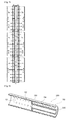
- an outflow pipe designed to provide pressure resistance against high pressure and used for the reverse osmosis method may not be used similar to those for the FO method or PRO method, and a flow rate obtained using the outflow pipe (1) used for the conventional FO or PRO method is small, since, as illustrated in FIG. 1 , the outflow pipe (1) has a structure in which an introduced fluid is discharged toward a separation membrane through an outflow holes (2) after a flow path of the introduced fluid is changed by a partitioning plate (3), and introduction of a fluid into the FO separation membrane or PRO separation membrane may not be improved, and a gradient of osmosis is not smooth.
- a helically wound membrane module for FO which has disclosed in Korean Patent Application No. 010-7023340 disclosed that only the osmosis module may include or may also not include a permeate tube for adopting one or more fluid streams or for collecting water, there was no description of how the permeate tube is formed, and how the effect was.
- a flow rate introduced into the osmosis separation membrane may be improved according to a configuration of the permeate tube to improve a flux of water through the osmosis separation membrane, and a porous penetrating water outflow pipe used for FO or PRO is clearly distinguished from an outflow pipe used for reverse osmosis, a study for the porous penetrating water outflow pipe used for the FO or the PRO is urgent.
- the present invention is directed to providing an porous outflow pipe for forward osmosis or pressure-retarded osmosis capable of reducing a differential pressure by concentrically arranging a bypass pipe having a small diameter inside a central pipe, improving a fluid flow in the pipe when serially connected, and smoothing the fluid flow into a forward osmosis or pressure-retarded osmosis separation membrane, and an osmosis module for forward or pressure-retarded osmosis including the same.
- a porous outflow pipe for forward osmosis or pressure-retarded osmosis including: a hollow pipe in which a plurality of first via holes and second via holes through which a fluid is introduced and discharged penetrate the hollow pipe and are formed in a lengthwise direction; a bypass pipe concentrically disposed inside the hollow pipe in the lengthwise direction; and a partitioning plate formed in a circumferential direction of the bypass pipe to mutually block a fluid introduced into the front end of the hollow pipe and another fluid introduced through the second via holes.
- a plurality of the porous outflow pipes for forward osmosis or pressure-retarded osmosis may be connected in series, and some of the fluid introduced from the bypass pipe disposed at the front to the hollow pipe disposed at the rear may be directly introduced into the hollow pipe connected adjacent to the rear through the bypass pipe, and the remaining fluid may be mixed with a fluid introduced from the hollow pipe disposed at the front, discharged to the outside through the first via holes, and introduced through the second via holes.
- the bypass pipe may be entirely disposed inside the hollow pipe in the lengthwise direction and may include a first portion in which third via holes through which the fluid is introduced and discharged penetrate the bypass pipe and are formed in the lengthwise direction and a second portion in which the third via holes are not formed.
- first portion and the second portion may be divided on the basis of the partitioning plate.
- the first portion may be disposed in front of the second portion.
- a first blocking plate which seals a remaining region except the first portion may be provided at the front end of the hollow pipe so that a fluid is introduced only into the bypass pipe.
- a second blocking plate may be provided at a rear end of the second portion to block discharging of a fluid.
- a rear end of the second portion included in the porous outflow pipe disposed at the front and a front end of the first portion included in the porous outflow pipe disposed at the rear may be connected each other.
- bypass pipe may be disposed only at the rear on the basis of the partitioning plate.
- a second blocking plate may be provided at the rear end of the bypass pipe to block discharging of a fluid.
- the partitioning plate may be disposed at a position corresponding to a half of an entire length of the hollow pipe.
- first via holes and the second via holes may be disposed at opposite sides of the partitioning plate as a boundary.
- a forward osmosis module including: the porous outflow pipe for forward osmosis that is any one of claims 1 to 12; and a plurality of separation membranes which helically wind an external circumferential surface of the porous outflow pipe in a circumferential direction.
- a pressure-retarded osmosis module including: the porous outflow pipe for pressure-retarded osmosis that is any one of claims 1 to 12; and a plurality of separation membranes which helically wind an external circumferential surface of the porous outflow pipe in a circumferential direction.
- An porous outflow pipe for forward osmosis or pressure-retarded osmosis and an osmosis module for forward or pressure-retarded osmosis has an advantage of reducing a differential pressure by concentrically arranging a bypass pipe having a small diameter inside a central pipe, improving a fluid flow in the pipes when serially connected, and smoothing the fluid flow into a forward osmosis or PRO separation membrane.
- a bypass pipe 120 or 220 is concentrically arranged inside of a hollow pipe 110
- some of the fluid A introduced from the bypass pipe 120 or 220 of the hollow pipe 110 disposed at the front to the hollow pipe 110 disposed at the rear is directly introduced into the hollow pipe 110 connected adjacent to the rear through the bypass pipe 120
- the other is mixed with the fluid B introduced from the hollow pipe 110 disposed at the front side and discharged to the outside through a first via hole 112 and flows into a second via hole 114, and thereby a differential pressure is decreased and a fluid flow becomes smooth.
- Such a porous outflow pipe for forward osmosis or pressure-retarded osmosis 100 or 200 includes the hollow pipe 110, the bypass pipe 120 or 220, and a partitioning plate 130.
- the hollow pipe 110 is installed to cross a central portion of an osmosis module 10 in a lengthwise direction and serves as a transfer pipe which transfer a fluid introduced from the outside to a separation membrane 30 in the lengthwise direction, wherein the separation membrane 30 covers an external circumferential surface.
- Such a hollow pipe 110 includes a pipe member having a predetermined length and a hollow shape, a plurality of first via holes 112 and second via holes 114 are formed at the external circumferential surface in the lengthwise direction, and thus a fluid supplied from the outside may be introduced and discharged.
- the first via holes 112 are provided in front of a partitioning plate 130 disposed in a direction which crosses inside of the hollow pipe 110, and the second via holes 114 are disposed at the rear of the partitioning plate 130 in the lengthwise direction.
- the first via holes 112 and the second via holes 114 serve as flow paths through which a fluid introduced into the front end of the hollow pipe 110 is discharged to the outside or introduced into the hollow pipe 110, and directions of a fluid flow in the first via hole 112 and the second via hole 114 are opposite each other.
- a fluid A introduced into the front end of the hollow pipe 110 is discharged to the outside only through the first via holes 112 and is moved toward the separation membrane 30, and a fluid B introduced into the hollow pipe 110 from the separation membrane 30 is introduced into the hollow pipe 110 only through the second via holes 114.
- the bypass pipe 120 or 220 is concentrically disposed at the inside of the hollow pipe 110 in the lengthwise direction so that some of the fluid introduced through the front end of the hollow pipe 110 is not discharged to the outside through the first via hole 112, directly moves toward the hollow pipe 110 connected to the rear end of the hollow pipe 110 in series, and thus reduces a differential pressure generated when connected in series.
- Such a bypass pipe 120 or 220 is provided with a pipe member having a predetermined length and a hollow shape similar to the hollow pipe 110.
- the bypass pipe 120 or 220 is provided to have a diameter less than that of the hollow pipe 110, the bypass pipe 120 or 220 is inserted into and disposed inside the hollow pipe 110, is supported by the partitioning plate 130 disposed in a circumferential direction of the bypass pipe 120 or 220, and is concentrically arranged with the hollow pipe 110.
- the partitioning plate 130 is disposed to cover the bypass pipe 120 or 220 at a position corresponding to a half of an entire length of the hollow pipe 110, the partitioning plate 130 serves to change a flow path of a fluid introduced into the front end of the hollow pipe 110.
- the partitioning plate 130 is provided to have a suitable thickness to endure a pressure of a fluid flowing inside of the hollow pipe 110, may generally include any material for a partitioning plate used for a porous outflow pipe for forward osmosis or pressure-retarded osmosis although may preferably include an epoxy hardener, and may also include a material such as a silicone, rubber, or the like.
- partitioning plate 130 is illustrated in the drawings to be positioned at the position corresponding to the half of the entire length of the hollow pipe 110, it is not limited thereto, and may also be positioned at various positions such as corresponding to one third or one fourth of the entire length of the hollow pipe 110.
- the bypass pipe 120 is provided to have an overall length approximately the same as that of the hollow pipe 110 and is disposed to occupy most of the inside of the hollow pipe 110.
- the bypass pipe 120 is provided with a first portion 121 in which third via holes 123 through which a fluid is introduced and discharged are formed and a second portion 122 in which the third via holes 123 are not formed.
- the first portion 121 and the second portion 122 are disposed inside the hollow pipe 110 to be disposed left and right with respect to the partitioning plate 130, and the first portion 121 in which the third via holes 123 are formed is disposed in front of the second portion 122.
- the porous outflow pipe for osmosis 100 when the porous outflow pipe for osmosis 100 according to the exemplary embodiment of the present invention is provided in plurality and connected in series so that ends of the bypass pipes 120 are connected to each other, some of a fluid A introduced from the bypass pipe 120 disposed at the front to the hollow pipe 110 disposed at the rear is directly introduced into the hollow pipe 110 connected adjacent to the rear through the bypass pipe 120, the other is mixed with a fluid B introduced from the hollow pipe 110 disposed at the front, discharged to the outside through the first via holes 112, and introduced into the second via holes 114.
- the fluid A introduced from the hollow pipe 110 disposed at the front refers to a fluid C which is discharged to the outside through the third via holes 123 and the first via holes 112, flows in the separation membrane 30, and flows the outside of the hollow pipe 110 and the fluid B which is diluted due to an osmotic action and is introduced into a space S1 formed between an internal circumferential surface of the hollow pipe 110 and an external circumferential surface of the bypass pipe 120 or 220 through the second via holes 114.
- a porous outflow pipe 100' disposed at the foremost end is provided with a first blocking plate 116 at a remaining portion of the front end excluding the bypass pipe 120 so that a fluid A introduced from the outside is introduced only into the first portion 121 of the bypass pipe 120.
- a porous outflow pipe 100" disposed at the rearmost end is provided with a second blocking plate 124 at the rear end of the second portion 122 for blocking a fluid from being discharged to the outside through an end portion of the bypass pipe 120.
- the fluid introduced into the porous outflow pipe 100" through the same process is blocked from being discharged to the outside by the second blocking plate 124 provided at the end portion of the second portion 122, the fluid is discharged to the outside through the space S1 covered by the external circumferential surface of the second portion 122, the partitioning plate 130, and the internal circumferential surface of the hollow pipe 110.
- bypass pipe 220 may also be provided shorter than the entire length of the hollow pipe 110 and disposed at part of the inside of the hollow pipe 110.
- bypass pipe 220 is only disposed at the rear side with respect to the partitioning plate 130 in the hollow pipe 110, and an additional third via hole 123 through which a fluid is introduced from and discharged to the outside is not formed.
- the porous outflow pipe for forward osmosis or pressure-retarded osmosis 100 or 200 may constitute a forward osmosis module or pressure-retarded osmosis module 10 in which a plurality of separation membranes 30 that helically wind the external circumferential surface in a circumferential direction are disposed and an external case 20 which accommodates the plurality of separation membranes 30.
- the separation membrane 30 is used for both forward osmosis and pressure-retarded osmosis and has a conventional structure forming a pocket shape by overlapping two separation membranes each other, a detail description thereof is omitted.
- the external case 20 also has a conventional structure used for the forward osmosis module or pressure-retarded osmosis module, a detail description thereof is omitted.
Landscapes
- Chemical & Material Sciences (AREA)
- Engineering & Computer Science (AREA)
- Water Supply & Treatment (AREA)
- Chemical Kinetics & Catalysis (AREA)
- Nanotechnology (AREA)
- Life Sciences & Earth Sciences (AREA)
- Hydrology & Water Resources (AREA)
- Environmental & Geological Engineering (AREA)
- Organic Chemistry (AREA)
- Separation Using Semi-Permeable Membranes (AREA)
Applications Claiming Priority (2)
| Application Number | Priority Date | Filing Date | Title |
|---|---|---|---|
| KR1020130165875A KR101397296B1 (ko) | 2013-12-27 | 2013-12-27 | 정삼투용 또는 압력지연 삼투용 다공성 유출관 및 이를 포함하는 정삼투 또는 압력지연 삼투 모듈 |
| PCT/KR2014/012339 WO2015099346A1 (fr) | 2013-12-27 | 2014-12-15 | Tube de sortie poreux pour osmose directe ou osmose retardée par pression, et module d'osmose directe ou d'osmose retardée par pression comprenant celui-ci |
Publications (4)
| Publication Number | Publication Date |
|---|---|
| EP3088068A1 true EP3088068A1 (fr) | 2016-11-02 |
| EP3088068A4 EP3088068A4 (fr) | 2017-10-18 |
| EP3088068C0 EP3088068C0 (fr) | 2024-08-07 |
| EP3088068B1 EP3088068B1 (fr) | 2024-08-07 |
Family
ID=50894725
Family Applications (1)
| Application Number | Title | Priority Date | Filing Date |
|---|---|---|---|
| EP14873867.7A Active EP3088068B1 (fr) | 2013-12-27 | 2014-12-15 | Module d'osmose directe ou d'osmose retardée par pression comprenant tube de sortie poreux |
Country Status (5)
| Country | Link |
|---|---|
| US (1) | US11020705B2 (fr) |
| EP (1) | EP3088068B1 (fr) |
| KR (1) | KR101397296B1 (fr) |
| CN (1) | CN105916572B (fr) |
| WO (1) | WO2015099346A1 (fr) |
Families Citing this family (13)
| Publication number | Priority date | Publication date | Assignee | Title |
|---|---|---|---|---|
| KR101632979B1 (ko) * | 2014-04-21 | 2016-07-29 | 에이.오.스미스(난징) 워터 트리트먼트 프로덕츠 컴퍼니 리미티드 | 측류 유동형 역삼투막 필터 |
| KR101618455B1 (ko) | 2014-11-17 | 2016-05-09 | 도레이케미칼 주식회사 | 삼투용 다공성 유출관 및 이를 포함하는 정삼투 또는 압력지연 삼투 모듈 |
| KR101584121B1 (ko) | 2015-02-13 | 2016-01-12 | 주식회사 휴비스워터 | 나권형 정삼투 분리막 모듈 및 이의 제조방법 |
| KR101726393B1 (ko) | 2015-06-02 | 2017-04-17 | 한국건설기술연구원 | 압력지연삼투용 반투과막의 세정이 가능한 해수담수화-발전 시스템 및 그 세정 방법 |
| KR101768336B1 (ko) * | 2015-11-02 | 2017-08-14 | 도레이케미칼 주식회사 | 삼투모듈용 다공성 유출관 및 이를 포함하는 정삼투 또는 압력지연 삼투모듈 |
| KR102462035B1 (ko) | 2016-03-31 | 2022-11-01 | 도레이첨단소재 주식회사 | 다공성 유출관 제조 장치 |
| KR102462036B1 (ko) | 2016-03-31 | 2022-11-01 | 도레이첨단소재 주식회사 | 다공성 유출관 |
| KR102467960B1 (ko) | 2016-03-31 | 2022-11-16 | 도레이첨단소재 주식회사 | 다공성 유출관 제조용 부착체 |
| KR102610683B1 (ko) * | 2016-10-07 | 2023-12-05 | 도레이첨단소재 주식회사 | 삼투모듈용 다공성 유출관 |
| CN106731109A (zh) * | 2016-12-19 | 2017-05-31 | 佛山市麦克罗美的滤芯设备制造有限公司 | 滤芯和具有其的净水设备 |
| CN109999673B (zh) * | 2019-05-08 | 2024-02-13 | 上海凯鑫分离技术股份有限公司 | 一种卷式膜元件 |
| GB202003685D0 (en) * | 2020-03-13 | 2020-04-29 | Ide Projects Ltd | Forward osmotic separation system and method |
| CN119612687A (zh) * | 2024-12-26 | 2025-03-14 | 浙江浙能兰溪发电有限责任公司 | 基于wtc反渗透工艺的电厂锅炉水处理应用方法及系统 |
Family Cites Families (18)
| Publication number | Priority date | Publication date | Assignee | Title |
|---|---|---|---|---|
| US3872014A (en) * | 1974-03-11 | 1975-03-18 | Aerojet General Co | Membrane separation apparatus |
| US4033878A (en) * | 1975-05-12 | 1977-07-05 | Universal Oil Products Company | Spiral wound membrane module for direct osmosis separations |
| US4080296A (en) * | 1977-03-28 | 1978-03-21 | The Dow Chemical Company | Hollow fiber permeator |
| US4670145A (en) * | 1986-07-08 | 1987-06-02 | E. I. Du Pont De Nemours And Company | Multiple bundle fluid separation apparatus |
| US5470469A (en) * | 1994-09-16 | 1995-11-28 | E. I. Du Pont De Nemours And Company | Hollow fiber cartridge |
| WO2009151709A2 (fr) * | 2008-03-20 | 2009-12-17 | Yale University | Module membranaire enroulé en spirale destiné à être utilisé en osmose directe |
| US8021550B2 (en) * | 2008-10-17 | 2011-09-20 | General Electric Company | Central core element for a separator assembly |
| US20100096308A1 (en) * | 2008-10-17 | 2010-04-22 | General Electric Company | Separator assembly |
| US8354026B2 (en) * | 2009-03-09 | 2013-01-15 | Hydration Systems, Llc | Center tube configuration for a multiple spiral wound forward osmosis element |
| EA027334B1 (ru) * | 2009-10-28 | 2017-07-31 | Оасис Уотер, Инк. | Способы прямого осмотического разделения |
| US20120174639A1 (en) * | 2011-01-11 | 2012-07-12 | Herron John R | Food Waste Concentration System and Related Processes |
| JP5961469B2 (ja) * | 2012-07-25 | 2016-08-02 | 日東電工株式会社 | スパイラル型正浸透膜エレメントおよび正浸透膜モジュール |
| GB2499740B (en) * | 2013-04-19 | 2015-09-16 | Ide Technologies Ltd | Osmosis apparatus |
| SG10201708806PA (en) * | 2013-04-26 | 2017-11-29 | Univ Nanyang Tech | A draw solute and an improved forward osmosis method |
| US10029212B2 (en) * | 2013-10-21 | 2018-07-24 | Toyobo Co., Ltd. | Hollow-fiber membrane element and membrane module for forward osmosis |
| US20150251930A1 (en) * | 2014-03-05 | 2015-09-10 | newterra Itd. | Differential reverse osmosis method and apparatus |
| KR20200035054A (ko) * | 2017-08-21 | 2020-04-01 | 케이에스알 아이피 홀딩스 엘엘씨. | 중심 신호 프로세서를 가지는 유도형 센서 모듈 조립체 |
| JP7155862B2 (ja) * | 2018-10-19 | 2022-10-19 | 東洋紡株式会社 | 中空糸膜エレメント、中空糸膜モジュールおよび正浸透水処理方法 |
-
2013
- 2013-12-27 KR KR1020130165875A patent/KR101397296B1/ko active Active
-
2014
- 2014-12-15 EP EP14873867.7A patent/EP3088068B1/fr active Active
- 2014-12-15 WO PCT/KR2014/012339 patent/WO2015099346A1/fr not_active Ceased
- 2014-12-15 US US15/102,822 patent/US11020705B2/en active Active
- 2014-12-15 CN CN201480067394.0A patent/CN105916572B/zh active Active
Also Published As
| Publication number | Publication date |
|---|---|
| KR101397296B1 (ko) | 2014-05-22 |
| US11020705B2 (en) | 2021-06-01 |
| CN105916572A (zh) | 2016-08-31 |
| EP3088068C0 (fr) | 2024-08-07 |
| WO2015099346A1 (fr) | 2015-07-02 |
| CN105916572B (zh) | 2018-03-13 |
| US20170036167A1 (en) | 2017-02-09 |
| EP3088068A4 (fr) | 2017-10-18 |
| EP3088068B1 (fr) | 2024-08-07 |
Similar Documents
| Publication | Publication Date | Title |
|---|---|---|
| US11020705B2 (en) | Porous outflow pipe for forward osmosis or pressure-retarded osmosis, and forward osmosis or pressure-retarded osmosis module comprising same | |
| Su et al. | Forward osmosis: an emerging technology for sustainable supply of clean water | |
| US10532938B2 (en) | Membrane filtration system with concentrate staging and concentrate recirculation, switchable stages, or both | |
| CN105121846B (zh) | 渗透装置 | |
| RU2012125859A (ru) | Осмотическая система перекачивания воды (варианты) | |
| CN111801152B (zh) | 膜分离系统及膜分离系统的运转方法 | |
| US11065580B2 (en) | Separation membrane element | |
| WO2013028324A1 (fr) | Ensemble de filtration comprenant de multiples modules partageant un support de fibres creuses commun | |
| US11014834B2 (en) | Osmotic concentration of produced and process water using hollow fiber membrane | |
| KR102567234B1 (ko) | 중공사막 엘리먼트, 중공사막 모듈 및 정침투수 처리 방법 | |
| EP3659694A1 (fr) | Module à membranes à fibres creuses | |
| EP3501627A1 (fr) | Module de membranes à fibres creuses plates et unité de séparation de membranes | |
| JP7133356B2 (ja) | 流路スペーサ及びスパイラル型膜エレメント | |
| WO2015125755A1 (fr) | Élément et module de membrane en fibres creuses | |
| KR101385362B1 (ko) | 삼투용 다공성 유출관 | |
| JP2015226864A (ja) | 正浸透用中空糸膜モジュール | |
| JP2015160157A (ja) | 中空糸膜モジュール | |
| KR101618454B1 (ko) | 삼투용 다공성 유출관 및 이를 포함하는 정삼투 또는 압력지연 삼투 모듈 | |
| KR101618455B1 (ko) | 삼투용 다공성 유출관 및 이를 포함하는 정삼투 또는 압력지연 삼투 모듈 | |
| JP5181917B2 (ja) | スパイラル型流体分離素子 | |
| KR101525310B1 (ko) | 정삼투용 또는 압력지연 삼투용 다공성 투과수 유출관 및 이를 포함하는 정삼투 또는 압력지연삼투 모듈 | |
| KR101572661B1 (ko) | 압력지연 삼투용 다공성 유출관 및 이를 포함하는 압력지연 삼투 모듈 | |
| JP7443761B2 (ja) | 中空糸膜モジュール | |
| KR101584121B1 (ko) | 나권형 정삼투 분리막 모듈 및 이의 제조방법 | |
| Hayashi et al. | High Permeability and Low Pressure CTA Hollow Fiber Reverse Osmosis Membrane “HOLLOSEP® HW” |
Legal Events
| Date | Code | Title | Description |
|---|---|---|---|
| PUAI | Public reference made under article 153(3) epc to a published international application that has entered the european phase |
Free format text: ORIGINAL CODE: 0009012 |
|
| 17P | Request for examination filed |
Effective date: 20160608 |
|
| AK | Designated contracting states |
Kind code of ref document: A1 Designated state(s): AL AT BE BG CH CY CZ DE DK EE ES FI FR GB GR HR HU IE IS IT LI LT LU LV MC MK MT NL NO PL PT RO RS SE SI SK SM TR |
|
| AX | Request for extension of the european patent |
Extension state: BA ME |
|
| RIN1 | Information on inventor provided before grant (corrected) |
Inventor name: SIM, YEON JU Inventor name: LEE, JONG HWA Inventor name: LEE, SUNG YUN |
|
| DAX | Request for extension of the european patent (deleted) | ||
| RIC1 | Information provided on ipc code assigned before grant |
Ipc: B01D 63/10 20060101ALI20170714BHEP Ipc: B01D 61/02 20060101AFI20170714BHEP Ipc: B01D 63/06 20060101ALI20170714BHEP Ipc: C02F 103/08 20060101ALI20170714BHEP Ipc: C02F 1/44 20060101ALI20170714BHEP Ipc: B01D 61/10 20060101ALI20170714BHEP Ipc: B01D 63/12 20060101ALI20170714BHEP Ipc: B01D 61/00 20060101ALI20170714BHEP |
|
| RIC1 | Information provided on ipc code assigned before grant |
Ipc: B01D 63/10 20060101ALI20170725BHEP Ipc: B01D 63/12 20060101ALI20170725BHEP Ipc: B01D 63/06 20060101ALI20170725BHEP Ipc: C02F 103/08 20060101ALI20170725BHEP Ipc: B01D 61/02 20060101AFI20170725BHEP Ipc: B01D 61/00 20060101ALI20170725BHEP Ipc: C02F 1/44 20060101ALI20170725BHEP Ipc: B01D 61/10 20060101ALI20170725BHEP |
|
| A4 | Supplementary search report drawn up and despatched |
Effective date: 20170914 |
|
| RIC1 | Information provided on ipc code assigned before grant |
Ipc: B01D 63/06 20060101ALI20170908BHEP Ipc: B01D 63/10 20060101ALI20170908BHEP Ipc: B01D 61/02 20060101AFI20170908BHEP Ipc: B01D 63/12 20060101ALI20170908BHEP Ipc: C02F 1/44 20060101ALI20170908BHEP Ipc: B01D 61/00 20060101ALI20170908BHEP Ipc: B01D 61/10 20060101ALI20170908BHEP Ipc: C02F 103/08 20060101ALI20170908BHEP |
|
| RAP1 | Party data changed (applicant data changed or rights of an application transferred) |
Owner name: TORAY ADVANCED MATERIALS KOREA INC. |
|
| STAA | Information on the status of an ep patent application or granted ep patent |
Free format text: STATUS: EXAMINATION IS IN PROGRESS |
|
| 17Q | First examination report despatched |
Effective date: 20200420 |
|
| GRAP | Despatch of communication of intention to grant a patent |
Free format text: ORIGINAL CODE: EPIDOSNIGR1 |
|
| STAA | Information on the status of an ep patent application or granted ep patent |
Free format text: STATUS: GRANT OF PATENT IS INTENDED |
|
| INTG | Intention to grant announced |
Effective date: 20240229 |
|
| GRAS | Grant fee paid |
Free format text: ORIGINAL CODE: EPIDOSNIGR3 |
|
| GRAA | (expected) grant |
Free format text: ORIGINAL CODE: 0009210 |
|
| STAA | Information on the status of an ep patent application or granted ep patent |
Free format text: STATUS: THE PATENT HAS BEEN GRANTED |
|
| AK | Designated contracting states |
Kind code of ref document: B1 Designated state(s): AL AT BE BG CH CY CZ DE DK EE ES FI FR GB GR HR HU IE IS IT LI LT LU LV MC MK MT NL NO PL PT RO RS SE SI SK SM TR |
|
| REG | Reference to a national code |
Ref country code: GB Ref legal event code: FG4D |
|
| REG | Reference to a national code |
Ref country code: CH Ref legal event code: EP |
|
| REG | Reference to a national code |
Ref country code: IE Ref legal event code: FG4D |
|
| REG | Reference to a national code |
Ref country code: DE Ref legal event code: R096 Ref document number: 602014090662 Country of ref document: DE |
|
| U01 | Request for unitary effect filed |
Effective date: 20240821 |
|
| U07 | Unitary effect registered |
Designated state(s): AT BE BG DE DK EE FI FR IT LT LU LV MT NL PT RO SE SI Effective date: 20240902 |
|
| PG25 | Lapsed in a contracting state [announced via postgrant information from national office to epo] |
Ref country code: NO Free format text: LAPSE BECAUSE OF FAILURE TO SUBMIT A TRANSLATION OF THE DESCRIPTION OR TO PAY THE FEE WITHIN THE PRESCRIBED TIME-LIMIT Effective date: 20241107 |
|
| PG25 | Lapsed in a contracting state [announced via postgrant information from national office to epo] |
Ref country code: PL Free format text: LAPSE BECAUSE OF FAILURE TO SUBMIT A TRANSLATION OF THE DESCRIPTION OR TO PAY THE FEE WITHIN THE PRESCRIBED TIME-LIMIT Effective date: 20240807 Ref country code: GR Free format text: LAPSE BECAUSE OF FAILURE TO SUBMIT A TRANSLATION OF THE DESCRIPTION OR TO PAY THE FEE WITHIN THE PRESCRIBED TIME-LIMIT Effective date: 20241108 |
|
| PG25 | Lapsed in a contracting state [announced via postgrant information from national office to epo] |
Ref country code: IS Free format text: LAPSE BECAUSE OF FAILURE TO SUBMIT A TRANSLATION OF THE DESCRIPTION OR TO PAY THE FEE WITHIN THE PRESCRIBED TIME-LIMIT Effective date: 20241207 |
|
| PG25 | Lapsed in a contracting state [announced via postgrant information from national office to epo] |
Ref country code: HR Free format text: LAPSE BECAUSE OF FAILURE TO SUBMIT A TRANSLATION OF THE DESCRIPTION OR TO PAY THE FEE WITHIN THE PRESCRIBED TIME-LIMIT Effective date: 20240807 |
|
| PG25 | Lapsed in a contracting state [announced via postgrant information from national office to epo] |
Ref country code: ES Free format text: LAPSE BECAUSE OF FAILURE TO SUBMIT A TRANSLATION OF THE DESCRIPTION OR TO PAY THE FEE WITHIN THE PRESCRIBED TIME-LIMIT Effective date: 20240807 Ref country code: RS Free format text: LAPSE BECAUSE OF FAILURE TO SUBMIT A TRANSLATION OF THE DESCRIPTION OR TO PAY THE FEE WITHIN THE PRESCRIBED TIME-LIMIT Effective date: 20241107 |
|
| U20 | Renewal fee for the european patent with unitary effect paid |
Year of fee payment: 11 Effective date: 20241226 |
|
| PG25 | Lapsed in a contracting state [announced via postgrant information from national office to epo] |
Ref country code: RS Free format text: LAPSE BECAUSE OF FAILURE TO SUBMIT A TRANSLATION OF THE DESCRIPTION OR TO PAY THE FEE WITHIN THE PRESCRIBED TIME-LIMIT Effective date: 20241107 Ref country code: PL Free format text: LAPSE BECAUSE OF FAILURE TO SUBMIT A TRANSLATION OF THE DESCRIPTION OR TO PAY THE FEE WITHIN THE PRESCRIBED TIME-LIMIT Effective date: 20240807 Ref country code: NO Free format text: LAPSE BECAUSE OF FAILURE TO SUBMIT A TRANSLATION OF THE DESCRIPTION OR TO PAY THE FEE WITHIN THE PRESCRIBED TIME-LIMIT Effective date: 20241107 Ref country code: IS Free format text: LAPSE BECAUSE OF FAILURE TO SUBMIT A TRANSLATION OF THE DESCRIPTION OR TO PAY THE FEE WITHIN THE PRESCRIBED TIME-LIMIT Effective date: 20241207 Ref country code: HR Free format text: LAPSE BECAUSE OF FAILURE TO SUBMIT A TRANSLATION OF THE DESCRIPTION OR TO PAY THE FEE WITHIN THE PRESCRIBED TIME-LIMIT Effective date: 20240807 Ref country code: GR Free format text: LAPSE BECAUSE OF FAILURE TO SUBMIT A TRANSLATION OF THE DESCRIPTION OR TO PAY THE FEE WITHIN THE PRESCRIBED TIME-LIMIT Effective date: 20241108 Ref country code: ES Free format text: LAPSE BECAUSE OF FAILURE TO SUBMIT A TRANSLATION OF THE DESCRIPTION OR TO PAY THE FEE WITHIN THE PRESCRIBED TIME-LIMIT Effective date: 20240807 |
|
| PG25 | Lapsed in a contracting state [announced via postgrant information from national office to epo] |
Ref country code: SM Free format text: LAPSE BECAUSE OF FAILURE TO SUBMIT A TRANSLATION OF THE DESCRIPTION OR TO PAY THE FEE WITHIN THE PRESCRIBED TIME-LIMIT Effective date: 20240807 |
|
| PG25 | Lapsed in a contracting state [announced via postgrant information from national office to epo] |
Ref country code: CZ Free format text: LAPSE BECAUSE OF FAILURE TO SUBMIT A TRANSLATION OF THE DESCRIPTION OR TO PAY THE FEE WITHIN THE PRESCRIBED TIME-LIMIT Effective date: 20240807 |
|
| PG25 | Lapsed in a contracting state [announced via postgrant information from national office to epo] |
Ref country code: SK Free format text: LAPSE BECAUSE OF FAILURE TO SUBMIT A TRANSLATION OF THE DESCRIPTION OR TO PAY THE FEE WITHIN THE PRESCRIBED TIME-LIMIT Effective date: 20240807 |
|
| PLBE | No opposition filed within time limit |
Free format text: ORIGINAL CODE: 0009261 |
|
| STAA | Information on the status of an ep patent application or granted ep patent |
Free format text: STATUS: NO OPPOSITION FILED WITHIN TIME LIMIT |
|
| PG25 | Lapsed in a contracting state [announced via postgrant information from national office to epo] |
Ref country code: MC Free format text: LAPSE BECAUSE OF FAILURE TO SUBMIT A TRANSLATION OF THE DESCRIPTION OR TO PAY THE FEE WITHIN THE PRESCRIBED TIME-LIMIT Effective date: 20240807 |
|
| 26N | No opposition filed |
Effective date: 20250508 |
|
| REG | Reference to a national code |
Ref country code: CH Ref legal event code: PL |
|
| GBPC | Gb: european patent ceased through non-payment of renewal fee |
Effective date: 20241215 |
|
| PG25 | Lapsed in a contracting state [announced via postgrant information from national office to epo] |
Ref country code: GB Free format text: LAPSE BECAUSE OF NON-PAYMENT OF DUE FEES Effective date: 20241215 |
|
| PG25 | Lapsed in a contracting state [announced via postgrant information from national office to epo] |
Ref country code: CH Free format text: LAPSE BECAUSE OF NON-PAYMENT OF DUE FEES Effective date: 20241231 |
|
| PG25 | Lapsed in a contracting state [announced via postgrant information from national office to epo] |
Ref country code: IE Free format text: LAPSE BECAUSE OF NON-PAYMENT OF DUE FEES Effective date: 20241215 |
|
| U20 | Renewal fee for the european patent with unitary effect paid |
Year of fee payment: 12 Effective date: 20251223 |