EP3088075A1 - Rührblatt und rührvorrichtung - Google Patents
Rührblatt und rührvorrichtung Download PDFInfo
- Publication number
- EP3088075A1 EP3088075A1 EP14874879.1A EP14874879A EP3088075A1 EP 3088075 A1 EP3088075 A1 EP 3088075A1 EP 14874879 A EP14874879 A EP 14874879A EP 3088075 A1 EP3088075 A1 EP 3088075A1
- Authority
- EP
- European Patent Office
- Prior art keywords
- blade
- stirring
- support part
- blade part
- impeller
- Prior art date
- Legal status (The legal status is an assumption and is not a legal conclusion. Google has not performed a legal analysis and makes no representation as to the accuracy of the status listed.)
- Granted
Links
Images



Classifications
-
- B—PERFORMING OPERATIONS; TRANSPORTING
- B01—PHYSICAL OR CHEMICAL PROCESSES OR APPARATUS IN GENERAL
- B01F—MIXING, e.g. DISSOLVING, EMULSIFYING OR DISPERSING
- B01F27/00—Mixers with rotary stirring devices in fixed receptacles; Kneaders
- B01F27/05—Stirrers
- B01F27/11—Stirrers characterised by the configuration of the stirrers
- B01F27/111—Centrifugal stirrers, i.e. stirrers with radial outlets; Stirrers of the turbine type, e.g. with means to guide the flow
- B01F27/1111—Centrifugal stirrers, i.e. stirrers with radial outlets; Stirrers of the turbine type, e.g. with means to guide the flow with a flat disc or with a disc-like element equipped with blades, e.g. Rushton turbine
-
- B—PERFORMING OPERATIONS; TRANSPORTING
- B01—PHYSICAL OR CHEMICAL PROCESSES OR APPARATUS IN GENERAL
- B01F—MIXING, e.g. DISSOLVING, EMULSIFYING OR DISPERSING
- B01F23/00—Mixing according to the phases to be mixed, e.g. dispersing or emulsifying
- B01F23/20—Mixing gases with liquids
- B01F23/23—Mixing gases with liquids by introducing gases into liquid media, e.g. for producing aerated liquids
- B01F23/233—Mixing gases with liquids by introducing gases into liquid media, e.g. for producing aerated liquids using driven stirrers with completely immersed stirring elements
-
- B—PERFORMING OPERATIONS; TRANSPORTING
- B01—PHYSICAL OR CHEMICAL PROCESSES OR APPARATUS IN GENERAL
- B01F—MIXING, e.g. DISSOLVING, EMULSIFYING OR DISPERSING
- B01F23/00—Mixing according to the phases to be mixed, e.g. dispersing or emulsifying
- B01F23/20—Mixing gases with liquids
- B01F23/23—Mixing gases with liquids by introducing gases into liquid media, e.g. for producing aerated liquids
- B01F23/233—Mixing gases with liquids by introducing gases into liquid media, e.g. for producing aerated liquids using driven stirrers with completely immersed stirring elements
- B01F23/2336—Mixing gases with liquids by introducing gases into liquid media, e.g. for producing aerated liquids using driven stirrers with completely immersed stirring elements characterised by the location of the place of introduction of the gas relative to the stirrer
- B01F23/23362—Mixing gases with liquids by introducing gases into liquid media, e.g. for producing aerated liquids using driven stirrers with completely immersed stirring elements characterised by the location of the place of introduction of the gas relative to the stirrer the gas being introduced under the stirrer
-
- B—PERFORMING OPERATIONS; TRANSPORTING
- B01—PHYSICAL OR CHEMICAL PROCESSES OR APPARATUS IN GENERAL
- B01F—MIXING, e.g. DISSOLVING, EMULSIFYING OR DISPERSING
- B01F27/00—Mixers with rotary stirring devices in fixed receptacles; Kneaders
- B01F27/05—Stirrers
- B01F27/11—Stirrers characterised by the configuration of the stirrers
- B01F27/114—Helically shaped stirrers, i.e. stirrers comprising a helically shaped band or helically shaped band sections
- B01F27/1144—Helically shaped stirrers, i.e. stirrers comprising a helically shaped band or helically shaped band sections with a plurality of blades following a helical path on a shaft or a blade support
Definitions
- the present invention relates to a stirring impeller intended for mixing and a stirring device including the same.
- a stirring device including a cylindrical stirred tank, a stirring shaft disposed at a central part of the stirred tank, and a stirring impeller attached to a lower part side of the stirring shaft is known as a stirring device that stirs an object to be stirred.
- a stirring impeller including a plate-shaped member attached to the stirring shaft and a plurality of flat plate-shaped blade parts fixed to an outer peripheral side of the plate-shaped member is known as a stirring impeller provided in this type of stirring device.
- a stirring impeller provided in this type of stirring device. According to this stirring device, if the stirring shaft rotates around an axis center, the stirring impeller rotates together with the stirring shaft, and the object to be stirred is stirred and mixed by this rotation.
- An object of the invention is to provide a stirring impeller with improved stirring efficiency and a stirring device including the same, in view of the above problems.
- a stirring impeller related to the invention is a stirring impeller to be attached to a stirring shaft provided in a stirring device.
- the stirring impeller includes a plate-shaped support part that is attached to the stirring shaft; and a plurality of blade units that are disposed on an outer peripheral edge side of the support part.
- the support part includes a first surface and a second surface.
- Each of the blade units includes a first blade part that protrudes from one of the first surface and the second surface in the support part, a second blade part that protrudes from the other one of the first surface and the second surface in the support part and is made unsymmetrical to the first blade part, and an opening that is formed in at least one of the first blade part and the second blade part.
- the support part may be formed in a circular shape.
- the plurality of blade units may be provided at predetermined intervals along a circumferential direction of the support part.
- the first blade part in one of two blade units adjacent to each other in the circumferential direction of the support part may be provided on the first surface of the support part
- the first blade part in the other one of the two adjacent blade units may be provided on the second surface of the support part
- the second blade part of the one blade unit may be provided on the second surface of the support part
- the second blade part of the other blade unit may be provided on the first surface of the support part.
- first blade part and the second blade part that are made asymmetrical to each other, for example, a configuration in which the first blade part is formed in a linear shape and the second blade part is formed in a curved shape may be adopted.
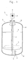
- a stirring impeller related to a first embodiment of the invention together with a stirring device including this stirring impeller will be described referring to Figs. 1 to 3 .
- the stirring impeller 4 is schematically illustrated by a dashed line, and the stirring impeller 4 is illustrated in detail in Figs. 2 and 3 .
- a stirring device 1 including the stirring impeller 4 of the present embodiment is a vertical stirring device.
- the stirring device 1 includes a stirred tank 2 that contains an object (liquid L) to be stirred, a stirring shaft 3 that is rotatably attached within the stirred tank 2, the stirring impeller 4 that is attached to the stirring shaft 3, and a driving unit 5 that rotates the stirring shaft 3.
- the stirring device 1 further includes a gas supply unit 6 that supplies another object (gas G) to be stirred into the stirred tank 2 from a bottom part 22 of the stirred tank 2.
- objects to be stirred that are contained in the stirred tank 2 are the liquid L and the gas G.
- the kind of object to be stirred is not particularly limited.
- the liquid L also includes liquid or the like with higher viscosity and lower flowability other than liquid with lower viscosity and higher flowability.
- the stirred tank 2 is formed in a cylindrical shape that is long in a longitudinal direction.
- the stirred tank 2 includes a cylindrical body part 21, a bottom part 22 that is attached to a lower end of the body part 21 and is semi-elliptical, dish-shaped, or the like in sectional shape, and a top part 23 that is attached to an upper end of the body part 21 and is semi-elliptical, dish-shaped, or the like in sectional shape.
- the stirred tank 2 holds the stirring shaft 3 so that an axial center direction A of the stirring shaft 3 coincides with a vertical direction (upward-downward direction of Fig. 1 ).
- the stirring shaft 3 is disposed at a central part of the stirred tank 2.
- a lower end part of the stirring shaft 3 is supported via a bearing (not illustrated) provided at the bottom part 22 of the stirred tank 2.
- an upper end part of the stirring shaft 3 extends above the top part 23 of the stirred tank 2, and is connected to the driving unit 5 (here, for example referred to as a motor M.) disposed above the top part 23.
- the stirring shaft 3 rotates under the driving of the driving unit 5.
- a configuration in which the lower end part of the stirring shaft 3 is not supported at all may be adopted as the stirring shaft 3.
- a configuration in which the lower end part of the stirring shaft 3 extends below the bottom part 22 and is connected to the driving unit 5 disposed below the bottom part 22 may be adopted.
- the stirring impeller 4 includes a cylindrical boss 41 that is attached to the stirring shaft 3, a tabular or circular (disk-shaped or doughnut-shaped) support part 42 that extends in a radial direction B of the stirring shaft 3 from the boss 41, and a plurality of blade units 43 that are attached to a peripheral edge part (outer peripheral edge side) of the support part 42.
- the support part 42, the boss 41, and the blade units 43 are fixed by welding or the like, respectively.
- the boss 41 has a through-hole 41a inserted through the stirring shaft 3.
- the stirring shaft 3 is inserted through the through-hole 41a of the boss 41.
- the stirring impeller 4 is attached to the stirring shaft 3 by the boss 41 and the stirring shaft 3 being screw-fastened, welded, or the like.
- the support part 42 is formed to protrude to the outer peripheral side in the radial direction B from an outer peripheral surface of the boss 41 so that the boss 41 is located at the center thereof. Additionally, the support part 42 is fixed to the boss 41 so as to be orthogonal to the axial center direction A of the stirring shaft 3.
- the length of the support part 42 in the radial direction B of the boss 41 can be appropriately designed according to the radius of the stirred tank 2, or the like, and can be, for example, about 20 to 50% of the diameter of the stirred tank 2, although not particularly limited.
- the plurality of blade units 43 are arranged at predetermined intervals along a circumferential direction of the support part 42.
- Each blade unit 43 is arranged so as not to jump out outward in the radial direction from the outer peripheral edge of the support part 42.
- an outer peripheral edge of each blade unit 43 and the outer peripheral edge of the support part 42 coincide with each other in a plan view.
- the blade unit 43 has a first blade part 43a that protrudes from an upper surface (first surface) 42a that is one surface of the support part 42 and is formed in a linear shape viewed in the radial direction, and a second blade part 43b that protrudes from a lower surface (second surface) 42b that is the other surface of the support part 42 and is formed in a curved shape viewed in the radial direction. Additionally, one end of the blade unit 43 is fixed to the support part 42, and the other end of the blade unit 43 is arranged at a certain distance from the support part 42. The support part 42 is rotated toward a side where the blade unit 43 is released.
- both of the blade parts 43a and 43b have asymmetrical shapes on the basis of the support part 42.
- the first blade part 43a is fixed to one surface of the support part 42 in a thickness direction.
- the second blade part 43b is fixed to the other surface of the support part 42.
- the first blade part 43a has an opening 44 at apart thereof.
- the opening 44 as illustrated in Fig. 2 , is formed such that predetermined regions on a root side and a radial outer side of the first blade part 43a are cut off in a linear shape, and has a space through which an object to be stirred passes.
- the opening 44 may be formed in the second blade part 43b. That is, the opening 44 may be formed in at least one (one or both) of the first blade part 43a and the second blade part 43b.
- the second blade part 43b is formed in a circular-arc curved shape viewed in the radial direction. This curved shape is not limited to a circular-arc shape, and may be, for example, a shape in which a plurality of linear portions are connected.
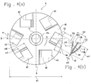
- the circular-arc curved shape of the second blade part 43b is, specifically, a shape that is indicated in Fig. 2(a) and that is cured with a constant curvature radius (for example, a curvature radius m5 illustrated in Fig. 4(b) ) between two end edges having a parallel relationship with a one-dot chain line showing a receding angle ⁇ .
- a constant curvature radius for example, a curvature radius m5 illustrated in Fig. 4(b)
- the second curved part may be formed, for example, in a shape that is curved with different curvature radii depending on portions.
- the second blade part has a shape of which the curvature radius is made different partially from the side of the second blade part 43b fixed to the support part 42 toward an end part of the second blade part 43b.
- the second blade part 43b of the present embodiment is formed with the same curvature radius in a direction along a one-dot chain line showing the receding angle ⁇ , the invention is not limited to this, and the second blade part may have different curvature radii in this direction. Specifically, the curvature radius of the second blade part 43b may also be changed from the outer peripheral side of the support part 42 toward the center side of the support part 42.
- the center side of the curvature radius in the second blade part 43b is located on the first blade part 43a, that is, on the support part 42 side. That is, the second blade part 43b has a shape that becomes concave with respect to the support part 42. Since the second blade part 43b is formed so that the center side of the curvature radius becomes the support part 42 side and the curved surface of the second blade part 43b protrudes in a direction away from the support part 42, the separation vortex of an object to be stirred that passes through an outer peripheral part of the first blade part 43a is not easily generated when the supporting part 42 has rotated in the direction (in the direction of the end part of the second blade part 43b) of an illustrated arrow.
- the position of the first blade part 43a and the position of the second blade part 43b are reversed. More specifically, as for one blade unit 43 (the blade unit 43 illustrated in Fig. 2(b) ) of two adjacent blade units 43, the first blade part 43a is formed on the first surface 42a of the support part 42. However, in the case of the other blade unit 43, the second blade part 43b is formed on the first surface 42a of the support part 42. Similarly, the second blade part 43b of one blade unit 43 is formed on the second surface 42b of the support part 42. However, in the case of the other blade unit 43, the first blade part 43a is formed on the second surface 42b of the support part 42.
- the arrangement and the size of the opening 44 between the first blade part 43a or the second blade part 43b are not particularly limited, and may be appropriately set so that suppression of cavitation and suppression of the strength reduction of the blade unit 43 are achieved.
- the opening 44 may be formed on a tip side in the first blade part 43a or the second blade part 43b, or may be formed on a radial inner side.
- the opening 44 is formed so as to be cut off in a linear shape in the present embodiment, the opening may be formed so as to be cut off in a curved shape. Additionally, the opening 44 may be formed as a hole of which the periphery is surrounded.
- one opening 44 is formed per one first blade part 43a, and a plurality of the openings may be formed. Additionally, openings 44 may be formed in a lattice or in a net. In addition, the driving force (drive torque) of the stirring impeller 4 can be further reduced if a larger opening 44 is formed.
- the blade unit 43 is disposed so as to incline to a downstream side in a rotational direction with respect to the radial direction B of the support part 42.
- the angle of such inclination to the downstream side that is, an angle (receding angle) ⁇ at which the inner peripheral side of the blade unit 43 retreats may be set to, for example, 10 degrees to 40 degrees.
- a configuration in which the blade unit 43 is not made to incline with respect to the radial direction may be adopted, or a configuration in which the inner peripheral side of the blade unit 43 advances may be adopted.
- the stirring device 1 including the stirring impeller 4 of the present embodiment will be described.
- the driving unit 5 of the stirring device 1 is driven to rotate the stirring shaft 3 in a direction (the counterclockwise direction of Fig. 2(a) ) in which a side where the first and second blade parts 43a and 43b protrude inclinedly becomes a downstream side
- the stirring impeller 4 rotates together with the stirring shaft 3 around the stirring shaft 3 within the stirred tank 2. If the stirring impeller 4 rotates, the liquid L and the gas G are mixed while being sheared by the first blade part 43a and the second blade part 43b.
- the stirring impeller 4 rotates in this way, the liquid L and the gas G (objects to be stirred) pass through the opening 44 toward the upstream side (rear side) from the downstream side (front side) in the rotational direction of the blade unit 43. Additionally, after an object to be stirred in a gap portion S between the first blade part 43a and the second blade part 43b, and the support part 42 has moved to the opening 44 with a centrifugal force, this object to be stirred joins the object to be stirred that passes through the above opening 44 and is dispersed further to the outer peripheral side than the blade unit 43. As mentioned above, since the objects to be stirred are made to join each other after the movement caused by the centrifugal force, it is preferable that the opening 44 is formed in a predetermined region on the radial outer side of the blade unit 43.
- the stirring impeller 4 of the present embodiment includes the support part 42 and the blade unit 43.
- the blade unit 43 has the first blade part 43a, the second blade part 43b, and the opening 44.
- the first blade part 43a and the second blade part 43b are asymmetrically formed viewed in the radial direction.
- the first blade part 43a in one blade unit 43 of two blade units 43 adjacent to each other in the circumferential direction is provided on the first surface 42a of the support part 42
- the first blade part 43a of the other blade unit 43 is provided on the second surface 42b of the support part 42
- the second blade part 43b of the one blade unit 43 is provided on the second surface 42b of the support part 42
- the second blade part 43b of the other blade unit 43 is provided on the first surface 42a of the support part 42.
- the opening 44 is formed in each first blade part 43a.
- the opening 44 is formed in an upper first blade part 43a in one blade unit 43 of two blade units 43 adjacent to each other, and the opening 44 is formed in a lower first blade part 43a of the other blade unit 43.
- the openings 44 are alternately arranged up and down, it is possible to decentralize gas reservoirs generated near the blade units 43 in an upward-downward direction. Accordingly, flooding does not easily occur.
- the flooding is a phenomenon in which the gas reservoirs adjacent to each other near the blade units 43 are combined together and the function of the blade units 43 degrades markedly.
- test data is illustrated below.
- test conditions are as follows.
- the stirring impeller 4 of the present embodiment provided for the performance test is made of stainless steel (SUS304), and has shapes illustrated in Fig. 2(a), Fig.2(b) , and Fig. 3 .
- the sizes of main parts are as follows, and the positions of dimensions (m1 to m7) of respective parts are illustrated in Fig. 4(a) and Fig. 4(b) .
- a general-purpose disk turbine impeller used as a target to be compared is an oblong plate-shaped disk in which the diameter of a disk having a disk shape is 99 mm, and blades are arranged along a radial direction of the disk.
- this turbine impeller six blades are arranged at regular intervals in a circumferential direction of the disk, the diameter dimension of a blade tip is 124 mm, and each blade has a vertical dimension of 25 mm and a horizontal dimension of 30 mm.
- the performance test was performed by changing the ventilation volume from 0 vvm to 3 vvm after the power at the time of non-ventilation was set to 1.0 kW/m3 in both of the impellers.
- An upper graph illustrated in Fig. 5 is a graph illustrating the relationship between the ventilation volume and kLa (overall mass transfer capacity coefficient). kLa shows that more gas is dissolved in liquid as the numerical value of kLa is larger. Additionally, a lower graph illustrated in Fig. 5 is a graph illustrating the relationship between the ventilation volume and power (per unit volume of liquid) transmitted to the liquid.
- stirring impeller 4 and the stirring device 1 related to the present embodiment are as above, the stirring impeller and the stirring device related to the invention are not limited to the above embodiment, and various changes can be made without departing from the scope of the invention. Additionally, the effects of the stirring impeller 4 and the stirring device 1 related to the invention are not limited to the above-described effects.
- the stirring impeller 4 an example in which six blade units 43 are provided at regular intervals in the circumferential direction has been mentioned as the stirring impeller 4.
- the invention is not limited to this.
- the number of blade units 43 may be appropriately set to, for example, 4 to 8 at regular intervals.
- the intervals between the blade units 43 may be appropriately set to different intervals.
- stirring shaft 3 and the stirring impeller 4 rotate in the counterclockwise direction viewed from the top part 23 side to the bottom part 22 side.
- an aspect in which the stirring shaft 3 and the stirring impeller 4 rotate in the clockwise direction may be adopted. In this case, flow reverse to that of the above embodiment is obtained as the flow of an object to be stirred.
- the stirring impeller and the stirring device related to the invention are not particularly limited.
- the stirring impeller and the stirring device of the invention are used for a reaction operation accompanied by the mass transfer of gas and liquid.
- a reaction operation a gas absorption reaction operation in a hydrogenation reaction tank, an oxidation reaction tank, or the like is mentioned.
- the stirring impeller and the stirring device of the invention are also used for a separation/extraction operation.
- the stirring impeller 4 related to the present embodiment is the stirring impeller 4 attached to the stirring shaft 3 provided in the stirring device 1, and includes the plate-shaped support part 42 that is attached to the stirring shaft 3, and the plurality of blade units 43 that are disposed on the outer peripheral edge side of the support part 42, the support part 42 has the first surface and the second surface, and each of the blade units 43 includes the first blade part 43a that protrudes from one of the first surface and the second surface of the support part 42, the second blade part 43b that protrudes from the other one of the first surface and the second surface in the support part 42 and is made asymmetrical to the first blade part 43a, and the opening 44 that is formed in at least one of the first blade part 43a and the second blade part 43b.
- this object to be stirred joins the object to be stirred that passes through the above opening 44 and is dispersed further to the outer peripheral side than the blade unit 43. Since gathering and stagnation in the object to be stirred in the gap portion between the first and second blade parts 43a and 43b and the support part 42 are suppressed by virtue of such a flow of the object to be stirred, cavitation can be suppressed. Since the resistance that the blade unit 43 receives decreases as much as the object to be stirred passes through the opening 44, the driving force of the stirring impeller 4 can be reduced.
- the support part 42 may be formed in a circular shape, the plurality of blade units 43 may be provided at predetermined intervals along the circumferential direction of the support part 42, the first blade part 43a of one blade unit 43 of two blade units 43 and 43 adjacent to each other in the circumferential direction of the support part 42 may be provided on the first surface of the support part 42, the first blade part 43a of the other blade unit 43 may be provided of the second surface of the support part 42, the second blade part 43b of the one blade unit 43 may be provided on the second surface of the support part 42, and the second blade part of the other blade unit may be provided on the first surface of the support part.
- first blade part 43a and the second blade part 43b that are made asymmetrical to each other, for example, a configuration in which the first blade part 43a is formed in a linear shape and the second blade part 43b is formed in a curved shape may be adopted.
- the stirring impeller 4 with improved stirring efficiency and the stirring device 1 including the stirring impeller 4 are provided.
Landscapes
- Chemical & Material Sciences (AREA)
- Chemical Kinetics & Catalysis (AREA)
- Mixers Of The Rotary Stirring Type (AREA)
Applications Claiming Priority (2)
| Application Number | Priority Date | Filing Date | Title |
|---|---|---|---|
| JP2013270311 | 2013-12-26 | ||
| PCT/JP2014/079194 WO2015098290A1 (ja) | 2013-12-26 | 2014-11-04 | 撹拌翼及び撹拌装置 |
Publications (3)
| Publication Number | Publication Date |
|---|---|
| EP3088075A1 true EP3088075A1 (de) | 2016-11-02 |
| EP3088075A4 EP3088075A4 (de) | 2017-10-04 |
| EP3088075B1 EP3088075B1 (de) | 2022-01-05 |
Family
ID=53478168
Family Applications (1)
| Application Number | Title | Priority Date | Filing Date |
|---|---|---|---|
| EP14874879.1A Active EP3088075B1 (de) | 2013-12-26 | 2014-11-04 | Rührblatt und rührvorrichtung |
Country Status (6)
| Country | Link |
|---|---|
| EP (1) | EP3088075B1 (de) |
| JP (1) | JP6393694B2 (de) |
| KR (1) | KR200487606Y1 (de) |
| CN (1) | CN205868121U (de) |
| TW (2) | TWM504636U (de) |
| WO (1) | WO2015098290A1 (de) |
Cited By (1)
| Publication number | Priority date | Publication date | Assignee | Title |
|---|---|---|---|---|
| EP3626810A4 (de) * | 2017-05-16 | 2021-01-27 | CJ Cheiljedang Corporation | Schaumbrecher für gärtank und mikroorganismengärtank mit schaumbrecher für gärtank |
Families Citing this family (4)
| Publication number | Priority date | Publication date | Assignee | Title |
|---|---|---|---|---|
| CN108465423A (zh) * | 2018-03-14 | 2018-08-31 | 桂林市兴美智能科技有限公司 | 一种新型节水灌溉装置 |
| CN109267828B (zh) * | 2018-12-07 | 2024-01-16 | 湖北科技学院 | 一种一对多电子钥匙及与之配合的防盗锁 |
| KR102196442B1 (ko) | 2019-03-21 | 2020-12-29 | 김석완 | 교반기용 교반날개 |
| CN110777029A (zh) * | 2019-12-11 | 2020-02-11 | 江西陶令酒业有限公司 | 一种用于白酒酒曲制造工艺的搅拌装置 |
Family Cites Families (12)
| Publication number | Priority date | Publication date | Assignee | Title |
|---|---|---|---|---|
| US2978233A (en) * | 1958-03-24 | 1961-04-04 | Davey Kingsley | Stabilized impeller |
| US3030083A (en) * | 1959-03-25 | 1962-04-17 | Hugh A Stiffler | Agitator wheel |
| CA945543A (en) * | 1969-09-02 | 1974-04-16 | Henry D. Porter | Single-stirrer-divided-chamber submersible three component semi-isolating mixer |
| JPS6359341A (ja) * | 1986-08-30 | 1988-03-15 | Toyoda Gosei Co Ltd | 撹拌用インペラ |
| JPH0372933A (ja) * | 1989-08-14 | 1991-03-28 | Hitachi Ltd | 攪拌翼 |
| EP0441505A1 (de) * | 1990-02-05 | 1991-08-14 | Imperial Chemical Industries Plc | Rührwerk |
| JP2987073B2 (ja) * | 1995-03-17 | 1999-12-06 | 株式会社日立製作所 | 攪拌翼、攪拌装置並びに攪拌方法 |
| KR100661788B1 (ko) * | 1999-08-12 | 2006-12-28 | 오또꿈뿌 오와이제이 | 슬러지로부터 고형물을 침출시키기 위한 방법 |
| FI109456B (fi) * | 1999-08-12 | 2002-08-15 | Outokumpu Oy | Laitteisto lietteen sisältämän kiintoaineen liuottamiseksi |
| JP2004035724A (ja) | 2002-07-03 | 2004-02-05 | Jsr Corp | ポリマー溶液の脱溶媒方法及び脱溶媒装置 |
| US20080199321A1 (en) * | 2007-02-16 | 2008-08-21 | Spx Corporation | Parabolic radial flow impeller with tilted or offset blades |
| JP2015502846A (ja) * | 2011-11-24 | 2015-01-29 | ワン、リーWANG, Li | チャンネル状羽根を有する撹拌インペラ |
-
2014
- 2014-11-04 JP JP2015554643A patent/JP6393694B2/ja active Active
- 2014-11-04 CN CN201490001136.8U patent/CN205868121U/zh not_active Expired - Lifetime
- 2014-11-04 KR KR2020167000023U patent/KR200487606Y1/ko not_active Expired - Lifetime
- 2014-11-04 EP EP14874879.1A patent/EP3088075B1/de active Active
- 2014-11-04 WO PCT/JP2014/079194 patent/WO2015098290A1/ja not_active Ceased
- 2014-11-19 TW TW103220529U patent/TWM504636U/zh not_active IP Right Cessation
- 2014-11-19 TW TW103140096A patent/TW201529155A/zh unknown
Cited By (1)
| Publication number | Priority date | Publication date | Assignee | Title |
|---|---|---|---|---|
| EP3626810A4 (de) * | 2017-05-16 | 2021-01-27 | CJ Cheiljedang Corporation | Schaumbrecher für gärtank und mikroorganismengärtank mit schaumbrecher für gärtank |
Also Published As
| Publication number | Publication date |
|---|---|
| JP6393694B2 (ja) | 2018-09-19 |
| JPWO2015098290A1 (ja) | 2017-03-23 |
| EP3088075A4 (de) | 2017-10-04 |
| EP3088075B1 (de) | 2022-01-05 |
| CN205868121U (zh) | 2017-01-11 |
| WO2015098290A1 (ja) | 2015-07-02 |
| KR20160002993U (ko) | 2016-08-30 |
| TW201529155A (zh) | 2015-08-01 |
| TWM504636U (zh) | 2015-07-11 |
| KR200487606Y1 (ko) | 2018-10-11 |
Similar Documents
| Publication | Publication Date | Title |
|---|---|---|
| EP3088075A1 (de) | Rührblatt und rührvorrichtung | |
| US10322386B2 (en) | Gas-liquid dispersion impeller assembly with annular-sector-shaped concave blades | |
| ES2628964T3 (es) | Pala de impulsor de flujo axial e impulsor de flujo axial | |
| CA2710179C (en) | Gas foil impeller | |
| ES2439710T3 (es) | Sistema que comprende un impulsor de mezcla con un borde de ataque en espiral, procedimiento de formación de dicho sistema, y procedimiento de tratamiento de un material utilizando dicho sistema | |
| EP3031519A1 (de) | Rührer | |
| EP2759336A2 (de) | Mischvorrichtung mit feststehendem Rohr | |
| CA2557098A1 (en) | Two phase flow conditioner for pumping gassy well fluid | |
| JP2015502846A (ja) | チャンネル状羽根を有する撹拌インペラ | |
| JP2001509226A (ja) | インペラー及びそれを組み込んだファン | |
| US5762417A (en) | High solidity counterflow impeller system | |
| CN102918280B (zh) | 混凝土蜗壳泵 | |
| JP2011007141A5 (de) | ||
| EP3128177B1 (de) | Querstrom-strömungspumpe | |
| CN112823052A (zh) | 用于消化池混合器的螺旋桨 | |
| BR112012008607B1 (pt) | ventilador axial | |
| CN106438471A (zh) | 轴流风轮和空调器 | |
| CN114215784A (zh) | 离心风叶、离心风机及空调 | |
| US10618018B2 (en) | Low wear radial flow impeller device and system | |
| CN114623087A (zh) | 用于空气压缩机的叶片、叶轮及空气压缩机 | |
| CN216642556U (zh) | 离心风叶、离心风机及空调 | |
| CN204061305U (zh) | 流体泵浦低紊流动叶轮 | |
| KR101530610B1 (ko) | 후향전곡깃 형태의 원심임펠러 | |
| KR100840179B1 (ko) | 자동차 연료 펌프용 임펠러 | |
| JP3128807U (ja) | 風圧を向上したファンモジュール |
Legal Events
| Date | Code | Title | Description |
|---|---|---|---|
| PUAI | Public reference made under article 153(3) epc to a published international application that has entered the european phase |
Free format text: ORIGINAL CODE: 0009012 |
|
| 17P | Request for examination filed |
Effective date: 20160504 |
|
| AK | Designated contracting states |
Kind code of ref document: A1 Designated state(s): AL AT BE BG CH CY CZ DE DK EE ES FI FR GB GR HR HU IE IS IT LI LT LU LV MC MK MT NL NO PL PT RO RS SE SI SK SM TR |
|
| AX | Request for extension of the european patent |
Extension state: BA ME |
|
| DAX | Request for extension of the european patent (deleted) | ||
| A4 | Supplementary search report drawn up and despatched |
Effective date: 20170901 |
|
| RIC1 | Information provided on ipc code assigned before grant |
Ipc: B01F 7/00 20060101ALI20170828BHEP Ipc: B01F 3/04 20060101ALI20170828BHEP Ipc: B01F 7/26 20060101AFI20170828BHEP |
|
| STAA | Information on the status of an ep patent application or granted ep patent |
Free format text: STATUS: EXAMINATION IS IN PROGRESS |
|
| 17Q | First examination report despatched |
Effective date: 20191104 |
|
| GRAP | Despatch of communication of intention to grant a patent |
Free format text: ORIGINAL CODE: EPIDOSNIGR1 |
|
| STAA | Information on the status of an ep patent application or granted ep patent |
Free format text: STATUS: GRANT OF PATENT IS INTENDED |
|
| INTG | Intention to grant announced |
Effective date: 20210805 |
|
| GRAS | Grant fee paid |
Free format text: ORIGINAL CODE: EPIDOSNIGR3 |
|
| GRAA | (expected) grant |
Free format text: ORIGINAL CODE: 0009210 |
|
| STAA | Information on the status of an ep patent application or granted ep patent |
Free format text: STATUS: THE PATENT HAS BEEN GRANTED |
|
| AK | Designated contracting states |
Kind code of ref document: B1 Designated state(s): AL AT BE BG CH CY CZ DE DK EE ES FI FR GB GR HR HU IE IS IT LI LT LU LV MC MK MT NL NO PL PT RO RS SE SI SK SM TR |
|
| REG | Reference to a national code |
Ref country code: GB Ref legal event code: FG4D |
|
| REG | Reference to a national code |
Ref country code: CH Ref legal event code: EP |
|
| REG | Reference to a national code |
Ref country code: AT Ref legal event code: REF Ref document number: 1460034 Country of ref document: AT Kind code of ref document: T Effective date: 20220115 |
|
| REG | Reference to a national code |
Ref country code: DE Ref legal event code: R096 Ref document number: 602014082092 Country of ref document: DE |
|
| REG | Reference to a national code |
Ref country code: IE Ref legal event code: FG4D |
|
| REG | Reference to a national code |
Ref country code: LT Ref legal event code: MG9D |
|
| REG | Reference to a national code |
Ref country code: NL Ref legal event code: MP Effective date: 20220105 |
|
| REG | Reference to a national code |
Ref country code: AT Ref legal event code: MK05 Ref document number: 1460034 Country of ref document: AT Kind code of ref document: T Effective date: 20220105 |
|
| PG25 | Lapsed in a contracting state [announced via postgrant information from national office to epo] |
Ref country code: NL Free format text: LAPSE BECAUSE OF FAILURE TO SUBMIT A TRANSLATION OF THE DESCRIPTION OR TO PAY THE FEE WITHIN THE PRESCRIBED TIME-LIMIT Effective date: 20220105 |
|
| PG25 | Lapsed in a contracting state [announced via postgrant information from national office to epo] |
Ref country code: SE Free format text: LAPSE BECAUSE OF FAILURE TO SUBMIT A TRANSLATION OF THE DESCRIPTION OR TO PAY THE FEE WITHIN THE PRESCRIBED TIME-LIMIT Effective date: 20220105 Ref country code: RS Free format text: LAPSE BECAUSE OF FAILURE TO SUBMIT A TRANSLATION OF THE DESCRIPTION OR TO PAY THE FEE WITHIN THE PRESCRIBED TIME-LIMIT Effective date: 20220105 Ref country code: PT Free format text: LAPSE BECAUSE OF FAILURE TO SUBMIT A TRANSLATION OF THE DESCRIPTION OR TO PAY THE FEE WITHIN THE PRESCRIBED TIME-LIMIT Effective date: 20220505 Ref country code: NO Free format text: LAPSE BECAUSE OF FAILURE TO SUBMIT A TRANSLATION OF THE DESCRIPTION OR TO PAY THE FEE WITHIN THE PRESCRIBED TIME-LIMIT Effective date: 20220405 Ref country code: LT Free format text: LAPSE BECAUSE OF FAILURE TO SUBMIT A TRANSLATION OF THE DESCRIPTION OR TO PAY THE FEE WITHIN THE PRESCRIBED TIME-LIMIT Effective date: 20220105 Ref country code: HR Free format text: LAPSE BECAUSE OF FAILURE TO SUBMIT A TRANSLATION OF THE DESCRIPTION OR TO PAY THE FEE WITHIN THE PRESCRIBED TIME-LIMIT Effective date: 20220105 Ref country code: ES Free format text: LAPSE BECAUSE OF FAILURE TO SUBMIT A TRANSLATION OF THE DESCRIPTION OR TO PAY THE FEE WITHIN THE PRESCRIBED TIME-LIMIT Effective date: 20220105 Ref country code: BG Free format text: LAPSE BECAUSE OF FAILURE TO SUBMIT A TRANSLATION OF THE DESCRIPTION OR TO PAY THE FEE WITHIN THE PRESCRIBED TIME-LIMIT Effective date: 20220405 |
|
| PG25 | Lapsed in a contracting state [announced via postgrant information from national office to epo] |
Ref country code: PL Free format text: LAPSE BECAUSE OF FAILURE TO SUBMIT A TRANSLATION OF THE DESCRIPTION OR TO PAY THE FEE WITHIN THE PRESCRIBED TIME-LIMIT Effective date: 20220105 Ref country code: LV Free format text: LAPSE BECAUSE OF FAILURE TO SUBMIT A TRANSLATION OF THE DESCRIPTION OR TO PAY THE FEE WITHIN THE PRESCRIBED TIME-LIMIT Effective date: 20220105 Ref country code: GR Free format text: LAPSE BECAUSE OF FAILURE TO SUBMIT A TRANSLATION OF THE DESCRIPTION OR TO PAY THE FEE WITHIN THE PRESCRIBED TIME-LIMIT Effective date: 20220406 Ref country code: FI Free format text: LAPSE BECAUSE OF FAILURE TO SUBMIT A TRANSLATION OF THE DESCRIPTION OR TO PAY THE FEE WITHIN THE PRESCRIBED TIME-LIMIT Effective date: 20220105 Ref country code: AT Free format text: LAPSE BECAUSE OF FAILURE TO SUBMIT A TRANSLATION OF THE DESCRIPTION OR TO PAY THE FEE WITHIN THE PRESCRIBED TIME-LIMIT Effective date: 20220105 |
|
| PG25 | Lapsed in a contracting state [announced via postgrant information from national office to epo] |
Ref country code: IS Free format text: LAPSE BECAUSE OF FAILURE TO SUBMIT A TRANSLATION OF THE DESCRIPTION OR TO PAY THE FEE WITHIN THE PRESCRIBED TIME-LIMIT Effective date: 20220505 |
|
| REG | Reference to a national code |
Ref country code: DE Ref legal event code: R097 Ref document number: 602014082092 Country of ref document: DE |
|
| PG25 | Lapsed in a contracting state [announced via postgrant information from national office to epo] |
Ref country code: SM Free format text: LAPSE BECAUSE OF FAILURE TO SUBMIT A TRANSLATION OF THE DESCRIPTION OR TO PAY THE FEE WITHIN THE PRESCRIBED TIME-LIMIT Effective date: 20220105 Ref country code: SK Free format text: LAPSE BECAUSE OF FAILURE TO SUBMIT A TRANSLATION OF THE DESCRIPTION OR TO PAY THE FEE WITHIN THE PRESCRIBED TIME-LIMIT Effective date: 20220105 Ref country code: RO Free format text: LAPSE BECAUSE OF FAILURE TO SUBMIT A TRANSLATION OF THE DESCRIPTION OR TO PAY THE FEE WITHIN THE PRESCRIBED TIME-LIMIT Effective date: 20220105 Ref country code: EE Free format text: LAPSE BECAUSE OF FAILURE TO SUBMIT A TRANSLATION OF THE DESCRIPTION OR TO PAY THE FEE WITHIN THE PRESCRIBED TIME-LIMIT Effective date: 20220105 Ref country code: DK Free format text: LAPSE BECAUSE OF FAILURE TO SUBMIT A TRANSLATION OF THE DESCRIPTION OR TO PAY THE FEE WITHIN THE PRESCRIBED TIME-LIMIT Effective date: 20220105 Ref country code: CZ Free format text: LAPSE BECAUSE OF FAILURE TO SUBMIT A TRANSLATION OF THE DESCRIPTION OR TO PAY THE FEE WITHIN THE PRESCRIBED TIME-LIMIT Effective date: 20220105 |
|
| PLBE | No opposition filed within time limit |
Free format text: ORIGINAL CODE: 0009261 |
|
| STAA | Information on the status of an ep patent application or granted ep patent |
Free format text: STATUS: NO OPPOSITION FILED WITHIN TIME LIMIT |
|
| PG25 | Lapsed in a contracting state [announced via postgrant information from national office to epo] |
Ref country code: AL Free format text: LAPSE BECAUSE OF FAILURE TO SUBMIT A TRANSLATION OF THE DESCRIPTION OR TO PAY THE FEE WITHIN THE PRESCRIBED TIME-LIMIT Effective date: 20220105 |
|
| 26N | No opposition filed |
Effective date: 20221006 |
|
| PG25 | Lapsed in a contracting state [announced via postgrant information from national office to epo] |
Ref country code: SI Free format text: LAPSE BECAUSE OF FAILURE TO SUBMIT A TRANSLATION OF THE DESCRIPTION OR TO PAY THE FEE WITHIN THE PRESCRIBED TIME-LIMIT Effective date: 20220105 |
|
| PG25 | Lapsed in a contracting state [announced via postgrant information from national office to epo] |
Ref country code: MC Free format text: LAPSE BECAUSE OF FAILURE TO SUBMIT A TRANSLATION OF THE DESCRIPTION OR TO PAY THE FEE WITHIN THE PRESCRIBED TIME-LIMIT Effective date: 20220105 |
|
| REG | Reference to a national code |
Ref country code: CH Ref legal event code: PL |
|
| GBPC | Gb: european patent ceased through non-payment of renewal fee |
Effective date: 20221104 |
|
| REG | Reference to a national code |
Ref country code: BE Ref legal event code: MM Effective date: 20221130 |
|
| PG25 | Lapsed in a contracting state [announced via postgrant information from national office to epo] |
Ref country code: LI Free format text: LAPSE BECAUSE OF NON-PAYMENT OF DUE FEES Effective date: 20221130 Ref country code: IT Free format text: LAPSE BECAUSE OF FAILURE TO SUBMIT A TRANSLATION OF THE DESCRIPTION OR TO PAY THE FEE WITHIN THE PRESCRIBED TIME-LIMIT Effective date: 20220105 Ref country code: CH Free format text: LAPSE BECAUSE OF NON-PAYMENT OF DUE FEES Effective date: 20221130 |
|
| PG25 | Lapsed in a contracting state [announced via postgrant information from national office to epo] |
Ref country code: LU Free format text: LAPSE BECAUSE OF NON-PAYMENT OF DUE FEES Effective date: 20221104 |
|
| PG25 | Lapsed in a contracting state [announced via postgrant information from national office to epo] |
Ref country code: IE Free format text: LAPSE BECAUSE OF NON-PAYMENT OF DUE FEES Effective date: 20221104 Ref country code: GB Free format text: LAPSE BECAUSE OF NON-PAYMENT OF DUE FEES Effective date: 20221104 |
|
| PG25 | Lapsed in a contracting state [announced via postgrant information from national office to epo] |
Ref country code: FR Free format text: LAPSE BECAUSE OF NON-PAYMENT OF DUE FEES Effective date: 20221130 Ref country code: BE Free format text: LAPSE BECAUSE OF NON-PAYMENT OF DUE FEES Effective date: 20221130 |
|
| PG25 | Lapsed in a contracting state [announced via postgrant information from national office to epo] |
Ref country code: HU Free format text: LAPSE BECAUSE OF FAILURE TO SUBMIT A TRANSLATION OF THE DESCRIPTION OR TO PAY THE FEE WITHIN THE PRESCRIBED TIME-LIMIT; INVALID AB INITIO Effective date: 20141104 |
|
| PG25 | Lapsed in a contracting state [announced via postgrant information from national office to epo] |
Ref country code: CY Free format text: LAPSE BECAUSE OF FAILURE TO SUBMIT A TRANSLATION OF THE DESCRIPTION OR TO PAY THE FEE WITHIN THE PRESCRIBED TIME-LIMIT Effective date: 20220105 |
|
| PG25 | Lapsed in a contracting state [announced via postgrant information from national office to epo] |
Ref country code: MK Free format text: LAPSE BECAUSE OF FAILURE TO SUBMIT A TRANSLATION OF THE DESCRIPTION OR TO PAY THE FEE WITHIN THE PRESCRIBED TIME-LIMIT Effective date: 20220105 |
|
| PG25 | Lapsed in a contracting state [announced via postgrant information from national office to epo] |
Ref country code: TR Free format text: LAPSE BECAUSE OF FAILURE TO SUBMIT A TRANSLATION OF THE DESCRIPTION OR TO PAY THE FEE WITHIN THE PRESCRIBED TIME-LIMIT Effective date: 20220105 |
|
| PG25 | Lapsed in a contracting state [announced via postgrant information from national office to epo] |
Ref country code: MT Free format text: LAPSE BECAUSE OF FAILURE TO SUBMIT A TRANSLATION OF THE DESCRIPTION OR TO PAY THE FEE WITHIN THE PRESCRIBED TIME-LIMIT Effective date: 20220105 |
|
| PGFP | Annual fee paid to national office [announced via postgrant information from national office to epo] |
Ref country code: DE Payment date: 20250930 Year of fee payment: 12 |