EP3088097B1 - Dispositifs et procédé de formage par pression de barrettes de liaison entre des parties d'une pièce à usiner en plaques - Google Patents
Dispositifs et procédé de formage par pression de barrettes de liaison entre des parties d'une pièce à usiner en plaques Download PDFInfo
- Publication number
- EP3088097B1 EP3088097B1 EP15165676.6A EP15165676A EP3088097B1 EP 3088097 B1 EP3088097 B1 EP 3088097B1 EP 15165676 A EP15165676 A EP 15165676A EP 3088097 B1 EP3088097 B1 EP 3088097B1
- Authority
- EP
- European Patent Office
- Prior art keywords
- forming
- tool
- workpiece
- stroke
- tool part
- Prior art date
- Legal status (The legal status is an assumption and is not a legal conclusion. Google has not performed a legal analysis and makes no representation as to the accuracy of the status listed.)
- Active
Links
Images




Classifications
-
- B—PERFORMING OPERATIONS; TRANSPORTING
- B21—MECHANICAL METAL-WORKING WITHOUT ESSENTIALLY REMOVING MATERIAL; PUNCHING METAL
- B21D—WORKING OR PROCESSING OF SHEET METAL OR METAL TUBES, RODS OR PROFILES WITHOUT ESSENTIALLY REMOVING MATERIAL; PUNCHING METAL
- B21D28/00—Shaping by press-cutting; Perforating
- B21D28/02—Punching blanks or articles with or without obtaining scrap; Notching
- B21D28/10—Incompletely punching in such a manner that the parts are still coherent with the work
-
- B—PERFORMING OPERATIONS; TRANSPORTING
- B21—MECHANICAL METAL-WORKING WITHOUT ESSENTIALLY REMOVING MATERIAL; PUNCHING METAL
- B21D—WORKING OR PROCESSING OF SHEET METAL OR METAL TUBES, RODS OR PROFILES WITHOUT ESSENTIALLY REMOVING MATERIAL; PUNCHING METAL
- B21D28/00—Shaping by press-cutting; Perforating
- B21D28/02—Punching blanks or articles with or without obtaining scrap; Notching
- B21D28/16—Shoulder or burr prevention, e.g. fine-blanking
-
- B—PERFORMING OPERATIONS; TRANSPORTING
- B21—MECHANICAL METAL-WORKING WITHOUT ESSENTIALLY REMOVING MATERIAL; PUNCHING METAL
- B21D—WORKING OR PROCESSING OF SHEET METAL OR METAL TUBES, RODS OR PROFILES WITHOUT ESSENTIALLY REMOVING MATERIAL; PUNCHING METAL
- B21D28/00—Shaping by press-cutting; Perforating
- B21D28/24—Perforating, i.e. punching holes
- B21D28/34—Perforating tools; Die holders
Definitions
- the invention also relates to a method for pressure forming a connecting web of the type mentioned carried out by means of the above forming tool and / or by means of the above machine tool.
- the previously known forming tool comprises a forming die with a bevelled punch tip and a forming die with a bearing surface and a die recess embedded in the bearing surface.
- the forming die is one, the forming die assigned to the other side of a connecting bridge to be processed.
- the forming punch is moved in the direction of the forming die with a machining stroke carried out along a stroke axis.
- the shaping stamp acts on the connecting web arranged between the shaping stamp and the shaping die with the bevelled stamp tip.
- the connecting web is squeezed while reducing the thickness of the connecting web between the shaping punch and the shaping die, and is also bent over an edge which is formed on the shaping die by the contact surface and a lateral boundary surface of the die recess running parallel to the stroke axis.
- a fracture zone of reduced cross-section is produced on the connecting web compared to the rest of the connecting web.
- a punching tool comprises a punch and a workpiece support, which are arranged on both sides of a workpiece to be machined.
- the punch has a raised peripheral edge with a triangular cross section.
- the workpiece support is provided with a flat support surface for a workpiece to be machined.
- the raised peripheral edge of the punch faces the flat support surface of the workpiece support.
- a first step the punch is moved along the stroke axis so far in the direction of the support surface of the workpiece support that the raised peripheral edge of the punch penetrates the workpiece in question and creates a V-shaped workpiece groove on the associated workpiece side, but between the raised peripheral edge of the punch on the one hand and the support surface of the workpiece support on the other hand, a residual thickness of the workpiece remains.
- a cutout is created on the workpiece in a subsequent step.
- JP H10 152136 A discloses an apparatus and a method for creating a predetermined breaking point for a ring-pull closure on a tin can.
- a wall area of the tin can supported on a flat support surface of the device, is acted upon on the side remote from the support surface by a cutting edge of a stamp such that a residual thickness of the machined wall of the tin can remains between the cutting edge of the stamp on the one hand and the support surface on the other hand.
- the object of the present invention is to enable a force-dependent control of the pressure conversion of connecting webs of the type described above.
- the forming tool according to the invention enables force-dependent control of the machining stroke of the tool parts of the forming tool.
- Mutual support of the tool parts effective along the stroke axis, bypassing the pressure-formed connecting web, is realized in that the first tool part has a portal-like shape and overlaps the connecting web to be formed during its processing.
- the portal supports of the first tool part are in the stroke end position of the two tool parts on the second tool part on the side next to the connecting web.
- the shaping element is arranged on the first tool part, which is designed like a portal, between the portal supports.
- a forming tool which, in addition to a first tool part provided with a forming element, comprises a second tool part which is provided with a continuously flat bearing surface and is consequently of simple design.
- the second tool part there is the possibility of to execute the second tool part as a disk-shaped component with a low overall height along the stroke axis of the forming tool.
- forming elements that are rigidly connected to the rest of the tool part are suitable, but also forming elements that are rotatably mounted on a base body of the first tool part and can consequently roll on the connecting web for pressure forming.
- the connecting web After the pressure forming of a connecting web, the connecting web only has a relatively small cross section, which is dimensioned such that the connection of the connecting web to the adjacent workpiece part can be released with little effort, for example by moving the machined workpiece back and forth. Regardless of this, the connecting web can be dimensioned before the pressure forming in such a way that it creates a load-bearing connection between the relevant workpiece parts.
- good parts can also be connected to one another or one or more good parts with a waste part, for example with a scrap skeleton, by connecting webs.
- the connecting webs can start, for example, at straight or curved edges, but also at corners of the workpiece parts connected to one another.
- the connecting webs should be aligned with the forming member of the first tool part in such a way that the connecting webs face the forming member along the stroke axis with surfaces and not with edges.
- material particles which are produced, for example, as chips when pressure-forming a connecting web can be removed from the processing point.
- the invention is in a preferred embodiment Provide at least one of the tool parts of the forming tool according to the invention with a corresponding suction. The removal of material particles from the processing point also prevents the material particles from leaving traces on the workpiece parts connected to one another via connecting webs and thereby reducing the quality of the workpiece processing.
- the machining stroke to be carried out for pressure forming a connecting web is controlled as a function of force.
- the tool parts of the forming tool according to the invention are arranged in tool holders, which are provided on opposite sides of the connecting web to be formed or the workpiece parts connected to one another by the connecting web to be formed, and which can be moved numerically controlled relative to one another along the stroke axis of the tool parts. There may also be the option of rotating the tool holders together with the tool parts attached to them about the stroke axis. Because of the geometry of the second tool part of the shaping tool according to the invention, however, it is generally not necessary to turn the tool holder in which the tool part provided with the continuously flat contact surface is accommodated.
- the previously machined workpiece usually rests on a conventional workpiece support of the machine tool.
- the connecting webs are positioned for processing relative to the tool parts of the forming tool held in the tool holders.
- a connecting web to be formed is pressurized on the one hand by the forming member of the first tool part and on the other hand is supported on the contact surface of the second tool part serving as an abutment for the first tool part.
- the line, along which the forming element of the first tool part dips into the connecting web can, for example, extend an extension of a separating surface that was created on the adjacent workpiece part when the connecting web was created, but it can also be placed upstream of this separating surface or opposite the separating surface into the interior of the Part of the workpiece must be set back.
- the forming element of the first tool part may overlap with a workpiece part, preferably in the order of tenths of a millimeter.
- the tool parts of the forming tool according to the invention perform a single machining stroke or several successive machining strokes relative to one another for shaping a connecting web.
- the forming method according to the invention is part of the cutting method according to the invention and also part of the machining method according to the invention, in the course of which the cutting method according to the invention and additionally a further workpiece machining are carried out.
- the forming tool according to the invention can be used to reshape the connecting bridge or bridges in a manner which is matched to the workpiece machining provided in addition to the separating machining.
- the connecting web (s) are formed on a workpiece part, to produce geometries such as those produced in the course of the additional workpiece machining on the remaining parting surface of the workpiece part in question.
- a parting surface is created on the workpiece side by the forming member. This circumstance is particularly important when the shaping element of the first tool part attaches to one end of the connecting web in question and consequently in the immediate vicinity of a workpiece part.
- the condition of the separating surface created by the forming member can be influenced. If the forming element has a sharp edge at the transition between its workpiece side and the free end of the first tool part, it creates a smooth and thus high-quality separating surface.
- the forming member of the first tool part on a workpiece side runs along the lifting axis parallel to the parting surface or at an angle with respect to the parting surface on the part of the workpiece which the workpiece side of the forming member faces during pressure forming of the connecting web. If the workpiece side of the forming member is parallel to the separating surface on the relevant workpiece part, then the separating surface created by means of the forming member on the relevant workpiece part also runs parallel to the separating surface of the workpiece part created prior to the pressure forming of the connecting web.
- a parting surface running parallel to the parting surface on the workpiece part in question is produced according to the invention in particular when the parting surface created by means of the forming part extends the existing parting surface on the part of the workpiece.
- the creation of a parting surface inclined at an angle to the already existing parting surface of the workpiece part by means of the shaping element is provided according to the invention, for example, in cases where before or after the shaping of the connecting web the parting surface already present on the workpiece part is reshaped by additional edge processing of the part and thereby beveled becomes.
- the inclined surface created on the workpiece by means of the forming member is aligned with the inclined surface which is created as part of the additional edge processing of the workpiece part.
- the first tool part in a preferred embodiment of the invention is designed as a tapering tool part, the shaping member of the first tool part tapering along the stroke axis towards the free end of the first tool part.
- This type of forming tool according to the invention is advantageous in particular with regard to the forming force to be applied for the pressure forming of a connecting web.
- a forming surface is provided on a web side of the forming member of the tapering tool part facing away from the workpiece side, which, starting from the free end of the tapering tool part, runs along the stroke axis away from the workpiece side of the forming member and accordingly is inclined to the stroke axis.
- material of the connecting bar is plasticized on the side of the connecting web assigned to the tapering tool part by means of the forming member of the tapering tool part and plasticized material of the connecting bar on the web side of the forming member displaced away from the workpiece side by the forming surface of the forming member.
- the shaping element of the tapering tool part creates a fracture zone at the relevant end of the connecting web due to its special geometry, which is such that after the connecting web has broken, no or only slight traces of the Remaining connecting web on the workpiece part. Because plasticized material of Connecting web, which is generated by the forming member, is displaced away from the workpiece side of the forming member and thus also from the workpiece part adjacent to the connecting web, the plasticized material of the connecting web can leave no or at most slight traces on the workpiece part in question. Burrs formed on the connecting web are removed together with the connecting web in the course of the separating method according to the invention and consequently does not impair the quality of the separating surface on the workpiece part.
- the forming member on the first tool part of the forming tool according to the invention can be different geometries.
- a forming element with a rectangular cross section is conceivable.
- the forming member of a tapered first tool part in a section plane running parallel to the stroke axis has a triangular cross section or a trapezoidal cross section.
- a forming element with a triangular cross section is linear on its end face.
- such a shaping element in a preferred embodiment of the invention can be provided with a slight flattening or rounding at the triangular tip forming the end face of the shaping element.
- a shaping element with a trapezoidal cross section has a flat design on its end face and is consequently less subject to wear during operation than a triangular shaped shaping element in cross section.
- Cross sections deviating from the trapezoidal shape, which form an end face on the shaping element of the tapering tool part are also conceivable according to the invention.
- a forming element with a triangular or with a trapezoidal cross section is provided in a further development of the invention in that the forming element of the tapering tool part is formed by a free end of the tapering tool part provided with an inner cavity, preferably an inner cone (claim 6).
- an inner cavity preferably an inner cone (claim 6).
- a connecting web is formed by pressure, material of the connecting web can flow into the interior of the inner cavity. This reduces the resistance, which one the connecting web opposes the processing by the forming tool according to the invention.
- a radius or a bevel can be provided at the transition between the free end of the tapered tool part and the inner cone.
- the radius and the bevel if necessary, ensure that the reshaped connecting web does not break at this point when the workpiece parts are finally separated, but rather where the reshaping element of the tapering tool part starts with the edge that is at the transition between the workpiece side of the reshaping element and the free end of the tapered tool part is formed.
- Claim 7 relates to a design of the forming tool according to the invention which is provided for this purpose and which permits a connecting web to be formed simultaneously at a plurality of locations spaced apart along the connecting web and thereby weakened for the complete separation of the workpiece parts connected to one another via the connecting web.
- Each of the forming points on the connecting web is processed by an organ section of the forming element provided on the first tool part.
- the forming member of the first tool part in a preferred embodiment of the invention extends in a circumferential direction and in particular in an arc shape, preferably along an arc, around the stroke axis.
- the extent of the shaping element in the circumferential direction can be dimensioned such that the shaping element acts simultaneously on several points of the connecting bar when a connecting bar is being shaped.
- An arcuate, in particular a circular course of the forming member offers the possibility of arranging the fracture zone, at which the connecting web is to break after the forming, on the workpiece part adjoining the connecting web in an area which is set back into the interior of the workpiece part compared to the parting surface already created on this workpiece part before the forming of the connecting web.
- a circular course of the forming member is also advantageous in that, by simply rotating the first tool part about a positioning axis concentric with the forming member, different organ sections of the forming member can be assigned to one and the same processing point and / or one and the same organ section to different processing points.
- the successive use of different organ sections of the forming element is particularly recommended due to the associated leveling of tool wear.
- the forming member of the first tool part is endless in the circumferential direction.
- a shaping element segmented in the circumferential direction is also conceivable.
- claim 15 provides that when machining a plate-like workpiece made of an elastically deformable material, the at least one connecting web is created as a solid-state joint and is resilient in the transverse direction of the separating surfaces of the workpiece parts connected to one another by the connecting web. If such a connecting web is formed by means of the shaping tool according to the invention, the connecting web can be compressed using its elasticity. Consequently, only a relatively small force is to be used to reshape the connecting web. This applies in particular in cases in which a connecting web is pressure-formed at both ends at the same time.
- FIG. 1 is a machine tool 1 designed as a punch laser combination machine.
- a machine frame 2 of the machine tool 1 has a C-shape and has an upper frame leg 3 and a lower frame leg 4.
- a laser cutting station 5 and a forming station 6 are provided at the free ends of the upper frame leg 3 and the lower frame leg 4.
- the laser cutting station 5 comprises a laser cutting head 7 on the upper frame arm 3 and a laser beam holder 8 on the lower frame arm 4.
- the forming station 6 has an upper tool holder 9 on the upper frame arm 3 and a lower tool holder 10 on the lower frame arm 4.
- An upper tool designed as a forming die 11 is inserted into the upper tool holder 9 as a first tool part, and a lower tool of a forming tool 13 designed as a forming die 12 is inserted into the lower tool holder 10 as a second tool part.
- the forming die 11 can be moved along a lifting axis 14 relative to the forming die 12 be raised and lowered.
- the upper tool holder 9 and the lower tool holder 10 can be rotated together with the forming die 11 and the forming die 12 about the lifting axis 14 (double arrow in FIG Figure 1 ). All functions of the machine tool 1 are controlled by a programmable numerical control.
- a sheet 15 are processed.
- the sheet 15 is moved by means of a conventional coordinate guide 16 with a two-axis horizontal movement over a workpiece support 17 of the machine tool 1 and thereby relative to the laser cutting head 7 and the laser beam holder 8 and also relative to the forming tool 13.
- Figure 1 the sheet 15 is shown broken off.
- the laser beam receptacle 8 and the lower tool receptacle 10 with the forming die 12 of the forming tool 13 can be seen in FIG. 1.
- the sheet 15 is first machined separately at the laser cutting station 5.
- a possible result of the separating processing of the sheet 15 is shown in Figure 2 shown.
- a laser beam directed by the laser cutting head 7 onto the sheet 15 cuts the sheet metal parts 19, 20, 21, 22 free while leaving connecting webs 23 free.
- the residual grid 18 and the sheet metal parts 19, 20, 21, 22 are only incompletely separated from one another.
- a different type of cutting tool in particular a punching tool that is inserted at the forming station 6, could also be used to incompletely separate the residual grid 18 and the sheet metal parts 19, 20, 21, 22.
- the sheet 15 is moved by means of the coordinate guide 16 to the forming station 6 of the machine tool 1.
- the connecting webs 23 are pressure-formed by means of the forming tool 13, which is inserted into the upper tool holder 9 and the lower tool holder 10.
- the forming tool 13 with the forming punch 11 provided as the upper tool and the forming die 12 provided as the lower tool and essentially cylindrical in the example shown is in Figure 3 shown.
- the forming die 11 has an axial end section which is designed as a forming member 24.
- the forming member 24 forms the free end of the forming die 11. How Figure 5 shows, the forming member 24 tapers along the stroke axis 14 to the free end of the forming die 11.
- the forming die 11 is consequently a tapered tool part of the forming tool 13.
- the axially parallel outer lateral surface of the forming die 11 and the end face 26 of the stamp-side forming member 24 form a sharp edge, which creates a smooth parting surface when the forming punch 11 is immersed in a connecting web 23 to be formed.
- the shaping member 24 has a trapezoidal cross section.
- the upper limit of the trapezoidal cross section of the forming member 24 is in Figure 5 indicated by an imaginary dashed line.
- the forming member 24 runs endlessly and concentrically with the stroke axis 14.
- a continuously flat bearing surface 27 is provided on the forming die 12. If the forming tool 13 with the forming die 11 is inserted into the upper tool holder 9 and with the forming die 12 into the lower tool holder 10 of the machine tool 1, the bearing surface 27 of the forming die 12 lies opposite the end face 26 of the die-side forming member 24 along the stroke axis 14. Both the support surface 27 of the forming die 12 and the end face 26 of the stamp-side forming member 24 extend perpendicular to the stroke axis 14.
- the processed sheet metal 15 is positioned by means of the coordinate guide 16 of the machine tool 1 relative to the forming tool 13 that is inserted at the forming station 6 such that the forming tool 13 is in a standby position for machining relative to the connecting web 23 to be formed.
- the forming punch 11 of the forming tool 13 is spaced along the stroke axis 14 from the top of the connecting web 23 and the workpiece parts adjacent to it.
- the support surface 27 of the forming die 12 has a minimal distance along the stroke axis 14 from the underside of the connecting web 23 and the workpiece parts connected by it.
- the forming die 11 is moved with a machining stroke along the stroke axis 14 in the direction of the forming die 12 to an end stroke position.
- the machining stroke is controlled depending on the path
- the machining stroke is controlled depending on the force.
- the amount of the machining stroke carried out by the forming die 11 relative to the forming die 12 is variably adjustable and depends in particular on the desired remaining thickness of the connecting web 23 after the forming.
- the path covered by the forming die 11 along the stroke axis 14 is recorded by means of a conventional path measuring system and forms the basis for controlling the stroke drive of the machine tool 1.
- the forming die 11 is immersed in the course of the machining stroke with diametrically opposed organ sections of the forming member 24 at both ends of the connecting web 23 in this and in the adjacent regions of the remaining grid 18 and the sheet metal part 20.
- a workpiece side 29 of the forming member 24 faces the residual grid 18, a workpiece side 30 of the forming member 24 faces the sheet metal part 20.
- Web sides 31, 32 of the shaping element 24 point to the connecting web 23 and are accordingly facing away from the residual mesh 18 and the sheet metal part 20.
- the workpiece sides 29, 30 of the forming member 24 on the forming die 11 run parallel to the lifting axis 14 and also parallel to a separating surface 33 created in the previous separating processing of the sheet on the residual grid 18 and a corresponding, in Figure 4 hidden separating surface on the sheet metal part 20.
- the shaping element 24 On the web sides 31, 32, the shaping element 24 has shaping surfaces 34, 35.
- the forming surfaces 34, 35 of the forming member 24, starting from the free end of the forming die 11, run along the stroke axis 14 away from the workpiece sides 29, 30 of the forming member 24.
- the cross-section of the connecting web 23 along the stroke axis 14 is reduced by pressure forming by means of the forming tool 13. Due to the excess of the diameter of the end face 26 of the stamp-side shaping element 24 relative to the connecting web 23, the reduced cross-sectional approaches of the connecting web 23 on the residual grille 18 and on the sheet metal part 20 are set back into the interior of the residual grid 18 and the sheet metal part 20 relative to the separating surfaces 33.
- a corresponding offset of the approaches of the cross-section-reduced connecting web 23 on the scrap skeleton 18 and on the sheet metal part 20 occurs when the separating surfaces 33 on the scrap skeleton 18 and the sheet metal part 20 are already in one piece during the separating processing of the sheet metal 15 prior to the pressure forming of the connecting webs 23 appropriate return are provided ( Figure 6 ).
- Figure 6 In this case, in the case of pressure forming following the separating processing of the sheet 15, only the connecting web 23 and not also an area directly adjoining the connecting web 23 is provided to process the remaining grid 18 and the sheet metal part 20. Accordingly, in the case of the processing situation Figure 6 to apply a lower force to the pressure forming of the connecting web 23 than in the conditions according to Figure 4 .
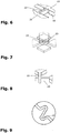
- FIG. 7 illustrates, for example, the processing of X-shaped intersecting processing webs 23, as are shown in FIG Figure 2 are provided between the sheet metal parts 19, 20, 21, 22.
- Figure 7 relates to the case where not only the connecting webs 23 themselves but also immediately adjacent workpiece areas are to be reshaped, while according to Figure 8 Workpiece areas directly adjacent to the connecting webs 23 have already been removed during the previous separating processing of the sheet 15 and consequently only the connecting webs 23 have to be reshaped.
- Figure 9 shows a connecting web 23 provided between two incompletely separated workpiece parts, which, like the rest of the separatively machined workpiece, consists of a resilient material and which was created with a meandering shape in the incomplete separation of the adjacent workpiece parts. Due to the material and because of its special shape, the connecting web 23 is resilient and accordingly forms a solid body joint between the two adjacent workpiece parts. If the connecting web 23 according to Figure 9 in the in Figure 5 illustrated way pressurized by the forming die 11 and the forming die 12 of the forming tool 13, the connecting web 23, due to its spring elasticity, only offers a relatively small resistance to the pressure forming. The spring elasticity of the connecting web 23 facilitates the displacement of plasticized material of the connecting web 23 away from the workpiece sides 29, 30 of the stamping member 24.
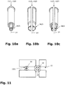
- FIGS. 10a, 10b and 10c show structurally different forming tools 13/1, 13/2, 13/3 from the forming tool 13 each in the scope of a forming die 11/1, 11/2, 11/3.
- a forming member 24/1 of the forming die 11/1 unlike the forming member 24 of the forming die 11, has an elliptical shape.
- the forming die 11/2 is divided in a plane parallel to the stroke axis 14 and consequently has a two-part forming member 24/2, each segment of the forming member 24/2 being semicircular.
- the forming die 11/3 has resulted from the forming die 11/1 by division along a plane running parallel to the stroke axis 14.
- a forming member 24/3 of the forming die 11/3 is consequently segmented and comprises two structurally identical halves.
- the forming members 24/1, 24/2, 24/3 of the forming die 11/1, 11/2, 11/3 have the same cross-sectional shape as the forming member 24 of the forming die 11. With the forming die 11/1, 11/2, 11 / 3 is consequently tapered tool parts of the forming tools 13/1, 13/2, 13/3.
- the forming dies 11/1, 11/2, 11/3 are each assigned a forming die 12, as shown in FIG Figure 3 is shown.
- a plurality of processing strokes of the forming tool 13/1 are carried out in succession at the ends of connecting webs 23.
- the forming die 11/1 is rotated by rotating the upper tool holder 9 about the lifting axis 14.
- a rotary setting of the forming die 12 cooperating with the forming die 11/1 is not necessary due to the geometry of the forming die 12.
- the processed sheet metal 15 positioned relative to the forming tool 13/1 by means of the coordinate guide 16 of the machine tool 1.
- a simple connecting web 23 is processed by means of the forming tool 13/2.
- the forming tool 13/3 is used for pressure forming two connecting webs 23 which intersect in an X-shape.
- the forming tools 13/2, 13/3 carry out pressure forming at both ends of a connecting web 23 with a single machining stroke, two successive machining strokes of the shaping tool 13/3 being required for machining the two X-shaped connecting webs and the shaping tool 13 / 3 is rotated about the stroke axis 14 after the first machining stroke.
- Figure 13 shows a first tool part of a forming tool 13/4 designed as a forming die 11/4.
- the forming die 11/4 is also a tapered tool part.
- the forming die 11/4 has a forming member 24/4 which forms a free end of the forming die 11/4 and which tapers along the stroke axis 14 towards the free end of the forming die 11/4.
- the stamping element 24/4 has a triangular cross section.
- An upper horizontal boundary line of the triangular cross section of the forming member 24/4 is in Figure 13 indicated by dashed lines.
- the forming die 11/4 processes a connecting web 23 only at one point in a machining stroke carried out for pressure forming the connecting web 23.
- the forming die 11/4 also acts for the pressure forming of a connecting web 23 with a forming die 12 in FIG Figure 3 shown together.
- FIG 14 the forming die 11/4 with the forming member 24/4 is immersed in the connecting web 23 at the right end of the connecting web 23 in the illustration.
- a workpiece side 36 of the forming member 24/4 running parallel to the lifting axis 14 faces the sheet metal part 20, a web side 37 of the forming member 24/4 faces away from the sheet metal part 20.
- the shaping member 24/4 is provided with a shaping surface 38 on the web side 37. Due to the dimensioning of the machining stroke carried out by the forming die 11/4 along the stroke axis 14, a residual thickness of the connecting web 23 remains when the connecting web 23 is pressure-formed.
- the workpiece side 36 of the forming member 24/4 is in the processing of the in Figure 14 Left end of the connecting web 23 facing the sheet metal part 21, the web side 37 of the forming member 24/4 faces away from the sheet metal part 21. Both during pressure forming of the connecting web 23 at its right end and during the forming of the connecting web 23 at its left end, plasticized material of the connecting web 23 is formed by the forming surface 38 on the web side 37 of the stamp-side forming member 24/4 from the workpiece side 36 of the forming member 24/4 ousted away
- the conditions according to Figure 15 differ from the processing situation accordingly Figure 14 in that the in Figure 14 As the web side 37 provided side of the forming member 24/4 forms a workpiece side 39. Accordingly, in Figure 15 the forming member 24/4 on the workpiece side 39 against the stroke axis 14 and consequently also against one in Figure 15 Separation surface 33 of the sheet metal part 21, not shown, parallel to the stroke axis, is inclined.
- the workpiece side 36 according to Figure 14 forms in Figure 15 a web side 40 parallel to the stroke axis of the forming member 24/4.
- the processing situation differs accordingly Figure 15 from the in Figure 14 conditions shown also by the amount of the machining stroke carried out by the forming die 11/4 along the stroke axis 14.
- the machining stroke of the forming die 11/4 is dimensioned such that only the forming member 24/4, which is triangular in cross section, and not also an adjoining axial section of the forming die 11/4 is immersed in the machined sheet 15.
- Figure 15 the machined sheet 15 is positioned opposite the forming tool 13/4 in such a way that the forming member 24/4 of the forming die 11/4 is arranged on the sheet metal part 21 on both sides of the shoulder of the connecting web 23 in the stroke end position of the forming tool 13 and consequently both Connecting web 23 and the sheet metal part 21 acted upon.
- the forming member 24/4 creates a chamfer on the edge of the sheet metal part 21 on the workpiece side 39 inclined against the stroke axis 14.
- the cross section of the connecting web 23 at the end of the connecting web 23 lying towards the sheet metal part 21 is reduced.
- a forming die 11/4 is shown as the first tool part of a forming tool 13/5.
- a forming member 24/5 of the forming die 11/5 has a rectangular cross section in a section plane running parallel to the stroke axis 14 and accordingly does not taper towards the free end of the forming die 11/5.
- the forming die 11/5 is consequently not a tapering tool part of the forming tool 13/5.
- the forming die 11/5 also acts for the pressure forming of connecting webs 23 with a forming die 12 provided as the second tool part of the forming tool 13/5 Figure 3 together.
- a first tool part of a forming tool 13/6 is designed as a forming die 11/6.
- the forming die 11/6 is a second tool part Figure 17 Forming die 12, not shown, according to Figure 3 assigned.
- a forming unit 41 of the forming die 11/6 coincides with the forming die 11 in accordance with Figure 3 match. Accordingly, the forming die 11/6 is a tapered tool part.
- the forming die 11/6 ends in a forming member 24/6 with a trapezoidal cross section.
- the forming die 11/6 has cheeks 42, 43 which protrude from the forming member 24/6 of the forming die 11/6 along the lifting axis 14 towards the forming die 12, not shown, and thereby protrusions 44, 45 of the forming die 11 / 6 train.
- the previously machined sheet 15 and the forming tool 13/6 are positioned relative to one another in such a way that during a machining stroke carried out from the forming punch 11/6 towards the forming die 12, the connecting web 23 to be formed between the projections 44, 45 of the Forming stamp 11/6 comes to rest.
- the projections 44, 45 of the stamping die 11/6 with their end faces leading along the stroke axis 14 on the contact surface 27 of the forming die 12.
- the protrusion of the projections 44, 45 relative to the shaping element 24/6 of the shaping stamp 11/6 is dimensioned such that when the shaping stamp 11/6 is in the end-of-stroke position, the free end of the shaping element 24/6 on the shaping stamp 11/6 from the support surface 27 the forming die 12 has a distance along the stroke axis 14 which corresponds to the desired residual thickness of the pressure-formed connecting web 23. In the stroke end position, the forming die 11/6 engages over the deformed connecting web 23 in a portal-like manner.
- the projections 44, 45 of the forming die 11/6 are laterally adjacent to the connecting web 23 in the manner of portal supports.
- the machining stroke carried out by the forming die 11/6 relative to the forming die 12 is force-controlled.
- integrated stroke control device 50 for the stroke drive of the forming tool 13/6 is provided.
- the stroke control device 50 comprises a force measuring device 51, an evaluation device 52 and an actuating device 53.
- the force measuring device 51 is used to measure the amount of supporting force with which the forming die 11/6 of the forming tool 13/6 is supported on the forming die 12 along the stroke axis 14.
- the evaluation device 52 the measured actual amount of the support force is compared with a limit amount of the support force stored in the stroke control device 50. If the measured actual amount of the support force reaches the predetermined limit, this indicates that the forming die 11/6 has reached its end-of-stroke position along the stroke axis 14. The evaluation device 52 then generates a switching signal for the actuating device 53.
- the actuating device 53 actuates the lifting drive of the forming tool 13/6 in such a way that the processing stroke of the forming die 11/6 directed towards the forming die 12 ends and starts Return stroke of the forming die 11/6 is initiated in the opposite direction of the machining stroke.
- a forming tool 13/7 is shown with a first tool part in the form of a forming stamp 11/7 and with a forming die 12 as a second tool part.
- Protrusions 46, 47 of the forming die 11/7 protrude along the lifting axis 14 with respect to a forming member 24/7 of the forming die 11/7 toward the forming die 12.
- the forming member 24/7 of the forming die 11/7 is correct in its structural design and in its functioning with the forming member 24/4 of the forming die 11/4 ( Figures 14 , 15 ) match.
- the forming die 11/7 is accordingly designed as a tapered tool part.
- Figure 19 shows a forming tool 13/8 with a first tool part designed as a forming stamp 11/8 and a second tool part designed as a forming die 12.
- a shaping element 24/8 corresponds in structure and operation to the shaping element 24/5 on the shaping punch 11/5 in accordance with Figure 16 . Accordingly, the forming die 11/8 is not a tapered tool part. Adjacent to the forming member 24/8 are projections 48, 49 on the forming die 11/8 along the stroke axis 14 towards the forming die 12.
- the machining stroke of the forming tool 13/7 according to Figure 18 and the machining stroke of the forming tool 13/8 according to Figure 19 are controlled depending on the force.
- the processes in the force-dependent control of the machining stroke of the forming tools 13/7, 13/8 correspond to those described above for the forming tool 11/6 Figure 17 described processes.
- Figure 20 illustrates a method step that is carried out during the processing of the sheet 15 in the illustrated example prior to the pressure forming of the connecting webs 23.
- sheet metal parts are edged on the upper side, which have previously been incompletely separated from one another by separating workpiece machining while leaving resilient connecting webs 23 in place.
- a forming roller 54 is used to carry out the edge processing and is inserted into the upper tool holder 9 at the forming station 6 of the machine tool 1.
- the forming roller 54 acts during the processing of the sheet metal parts of a sheet that has been previously cut with a in Figure 20 Counter-pressure roller, not shown, together, which is inserted into the lower tool holder 10 of the machine tool 1 and which bears against the underside of the machined sheet with a cylindrical outer surface.
- the forming roller 54 is provided with a double-conical bead 55 which has two conical forming surfaces 56, 57.
- the sheet metal parts in the exemplary case according to FIG Figure 2 the sheet metal parts 19, 20, 21, 22 of the processed sheet 15, from the associated residual grid (residual grid 18 in Figure 2 ) solved. Due to the reduction in cross-section of the connecting webs 23, shaking the processed sheet 15 is sufficient for this. As a result of the load acting thereby, the connecting webs 23 break in the fracture zones produced by pressure forming.
- the reduced-diameter projections of the connecting webs 23 are set back into the interior of the sheet metal parts, so that the remains of the connecting webs 23 on the sheet metal parts do not protrude the parting surfaces of the sheet metal parts created before the pressure forming of the connecting webs 23.
Landscapes
- Engineering & Computer Science (AREA)
- Mechanical Engineering (AREA)
- Mounting, Exchange, And Manufacturing Of Dies (AREA)
Claims (16)
- Outil de mise en forme dévolu au formage sous pression d'une membrure de liaison (23) attenante à des parties (18, 19, 20, 21, 22) d'une pièce, par ses extrémités, et reliant les unes aux autres lesdites parties (18, 19, 20, 21, 22) de la pièce qui se présentent comme des produits d'un usinage séparatif d'une pièce du type plaque, d'une tôle (15) en particulier, et sont respectivement munies d'une surface de séparation (33) dans la direction transversale de laquelle ladite membrure de liaison (23) s'étend,• comprenant deux parties d'outil qui, lors du formage sous pression de la membrure de liaison (23), sont affectées à des côtés mutuellement opposés de ladite membrure de liaison (23) et peuvent être mues, l'une par rapport à l'autre, le long d'un axe de déplacement (14) s'étendant dans la direction transversale de la membrure de liaison (23) au cours du formage sous pression de ladite membrure de liaison (23),• une première partie, au sein desdites parties de l'outil, étant pourvue d'un organe (24/6, 24/7, 24/8) de mise en forme qui matérialise, au moins partiellement, une extrémité libre de ladite première partie de l'outil,• sachant que la seconde partie (12) de l'outil est dotée d'une surface de support (27) qui est dédiée à la membrure de liaison (23), s'étend dans la direction transversale de l'axe de déplacement (14) et est tournée vers l'extrémité libre de la première partie dudit outil, et• sachant que les deux parties de l'outil peuvent être mues en direction l'une de l'autre le long de l'axe de déplacement (14), en accomplissant une course d'usinage, vers un emplacement de fin de course auquel l'organe (24/6, 24/7, 24/8) de mise en forme de la première partie de l'outil et la surface de support (27) de la seconde partie (12) dudit outil sont mutuellement espacés, le long dudit axe de déplacement (14), d'une distance inférieure, lors du formage sous pression de la membrure de liaison (23), à l'étendue de ladite membrure de liaison (23) devant être mise en forme le long dudit axe de déplacement (14), emplacement auquel ladite membrure de liaison (23) est en appui, au cours du formage sous pression, contre ladite surface de support (27) de la seconde partie (12) de l'outil,• laquelle surface de support (27) de la seconde partie (12) de l'outil est réalisée sous la forme d'une surface à planéité continue et se trouve, au cours du formage sous pression de la membrure de liaison (23), en vis-à-vis de l'organe (24/6, 24/7, 24/8) de mise en forme de la première partie dudit outil, le long de l'axe de déplacement (14), par une zone de surface située dans l'alignement de la région restante de ladite surface de support (27) de la seconde partie (12) de l'outil, dans la direction transversale dudit axe de déplacement (14), et• sachant que la première partie de l'outil comporte une saillie (44, 45, 46, 47, 48, 49) qui s'étend le long de l'axe de déplacement (14), en direction de la seconde partie dudit outil, et par l'intermédiaire de laquelle les deux parties dudit outil, mues vers l'emplacement de fin de course, sont en appui l'une contre l'autre le long dudit axe de déplacement (14), avec contournement de la membrure de liaison (23), du fait que ladite première partie de l'outil présente une configuration de type portique comprenant des montants donnant naissance à ladite saillie (44, 45, 46, 47, 48, 49) et l'organe (24/6, 24/7, 24/8) de mise en forme, interposé entre lesdits montants du portique, sachant que, lors du formage sous pression de la membrure de liaison (23), ladite première partie de l'outil se trouve en surplomb de ladite membrure de liaison (23) à la manière d'un portique et que, lorsque les deux parties de l'outil occupent l'emplacement de fin de course, elle repose sur la seconde partie dudit outil par lesdits montants du portique, en jouxtant latéralement ladite membrure de liaison (23).
- Outil de mise en forme selon la revendication 1, caractérisé par le fait que l'organe (24/6, 24/7, 24/8) de mise en forme de la première partie dudit outil comporte un côté pièce (29, 30, 36, 39), tourné vers l'une des parties (18, 19, 20, 21, 22) de ladite pièce au cours du formage sous pression de la membrure de liaison (23) ; et par le fait que ledit organe (24/6, 24/7, 24/8) de mise en forme de ladite première partie de l'outil s'étend le long de l'axe de déplacement (14) au niveau dudit côté pièce (29, 30, 36), parallèlement à la surface de séparation (33), sur la partie (18, 19, 20, 21, 22) de ladite pièce vers laquelle ledit côté pièce (29, 30, 36) dudit organe (24/6, 24/7, 24/8) de mise en forme est tourné au cours du formage sous pression de ladite membrure de liaison (23) ; ou par le fait que ledit organe (24/7) de mise en forme de ladite première partie de l'outil s'étend le long dudit axe de déplacement (14), au niveau dudit côté pièce (39), en décrivant un angle par rapport à ladite surface de séparation (33), sur la partie (18, 19, 20, 21, 22) de ladite pièce vers laquelle ledit côté pièce (39) dudit organe (24/7) de mise en forme est tourné au cours du formage sous pression de ladite membrure de liaison (23).
- Outil de mise en forme selon l'une des revendications précédentes, caractérisé par le fait que la première partie dudit outil est réalisée sous la forme d'une partie d'outil (11/6, 11/7) s'amenuisant, en ce sens que ladite première partie de l'outil est pourvue d'un organe (24/6, 24/7) de mise en forme qui s'amenuise, le long de l'axe de déplacement (14), en direction de l'extrémité libre de ladite première partie dudit outil.
- Outil de mise en forme selon la revendication 3, caractérisé par le fait que l'organe (24/6, 24/7) de mise en forme de la partie d'outil (11/6, 11/7) s'amenuisant comprend un côté pièce (29, 30, 36, 39) et un côté membrure (31, 32, 37, 40), sachant que, lors du formage sous pression de la membrure de liaison (23), ledit côté pièce (29, 30, 36, 39) de l'organe (24/6, 24/7) de mise en forme est tourné vers l'une des parties (18, 19, 20, 21, 22) de ladite pièce et le côté membrure (31, 32, 37, 40) dudit organe (24/6, 24/7) de mise en forme pointe à l'opposé de cette partie (18, 19, 20, 21, 22) de ladite pièce ; et par le fait qu'une surface (34, 35, 38) de mise en forme, prévue au niveau dudit côté membrure (31, 32, 37) dudit organe (24/6, 24/7) de mise en forme, s'éloigne dudit côté pièce (29, 30, 36) dudit organe (24/6, 24/7) de mise en forme, le long de l'axe de déplacement (14), depuis l'extrémité libre de ladite partie d'outil (11/6, 11/7) s'amenuisant.
- Outil de mise en forme selon la revendication 3 ou la revendication 4, caractérisé par le fait que l'organe (24/6, 24/7) de mise en forme de la partie d'outil (11/6, 11/7) s'amenuisant est muni d'une section transversale triangulaire, ou d'une section transversale trapézoïdale, dans un plan de coupe s'étendant parallèlement à l'axe de déplacement (14).
- Outil de mise en forme selon l'une des revendications 3 à 5, caractérisé par le fait que l'organe (24/6) de mise en forme de la partie d'outil (11/6) s'amenuisant est formé par une région extrême de ladite partie d'outil (11/6) s'amenuisant qui est dotée d'une cavité intérieure, de préférence d'un cône intérieur (25).
- Outil de mise en forme selon l'une des revendications précédentes, caractérisé par le fait que l'organe (24/6) de mise en forme de la première partie dudit outil est muni de tronçons qui sont décalés les uns des autres et au moyen desquels, au cours du formage sous pression, la membrure de liaison (23) peut être mise en forme, sous pression, en plusieurs zones décalées les unes des autres le long de ladite membrure de liaison (23),• sachant que ledit organe (24/6) de mise en forme est muni, à chaque fois, d'un côté pièce (29, 30) et d'un côté membrure (31, 32) au niveau des tronçons dudit organe, et• sachant que les côtés pièce (29, 30) des tronçons dudit organe sont tournés vers différentes parties (18, 19, 20, 21, 22) de la pièce, et que les côtés membrure (31, 32) desdits tronçons dudit organe pointent à l'opposé de différentes parties (18, 19, 20, 21, 22) de ladite pièce.
- Outil de mise en forme selon l'une des revendications précédentes, caractérisé par le fait que l'organe (24/6) de mise en forme de la première partie dudit outil s'étend notamment sous une forme arquée dans une direction périphérique, autour de l'axe de déplacement (14), de préférence le long d'un arc de cercle.
- Outil de mise en forme selon la revendication 8, caractérisé par le fait que l'organe (24/6) de mise en forme de la première partie dudit outil présente une réalisation sans fin dans la direction périphérique.
- Machine-outil équipée d'un outil (13/6, 13/7, 13/8) de mise en forme dévolu au formage sous pression d'une membrure de liaison (23) attenante à des parties (18, 19, 20, 21, 22) d'une pièce et reliant les unes aux autres lesdites parties (18, 19, 20, 21, 22) de la pièce qui se présentent comme des produits d'un usinage séparatif d'une pièce du type plaque, d'une tôle (15) en particulier, et sont respectivement munies d'une surface de séparation (33) dans la direction transversale de laquelle ladite membrure de liaison (23) s'étend, caractérisée par le fait que l'outil de mise en forme, selon l'une des revendications 1 à 9, est prévu en tant qu'outil (13/6, 13/7, 13/8) de mise en forme.
- Machine-outil selon la revendication 10, caractérisée par le fait que l'outil (13/6, 13/7, 13/8) de mise en forme comporte, pour les deux parties de l'outil, un entraînement en translation équipé d'un dispositif (50) de commande de courses qui comprend, pour sa part, un dispositif (51) mesureur de forces, un dispositif d'évaluation (52) connecté audit dispositif (51) mesureur de forces, ainsi qu'un dispositif d'actionnement (53) connecté audit dispositif d'évaluation (52) du dispositif (50) de commande de courses, et audit entraînement en translation,• sachant que le dispositif (51) mesureur de forces du dispositif (50) de commande de courses permet de mesurer, lors de la course d'usinage des deux parties de l'outil (13/6, 13/7, 13/8) de mise en forme, la valeur de la force d'appui avec laquelle lesdites deux parties de l'outil sont en appui l'une contre l'autre, par l'intermédiaire de la saillie (44, 45, 46, 47, 48, 49) s'étendant le long de l'axe de déplacement (14),• sachant que le dispositif d'évaluation (52) dudit dispositif (50) de commande de courses permet de comparer ladite valeur de la force d'appui, mesurée au moyen dudit dispositif (51) mesureur de forces, à une valeur limite de ladite force d'appui affectée à l'emplacement de fin de course des deux parties de l'outil, et• sachant que le dispositif d'évaluation (52) dudit dispositif (50) de commande de courses permet d'engendrer, à l'instant auquel ladite valeur limite de la force d'appui est atteinte ou dépassée, un signal de commutation qui est destiné au dispositif d'actionnement (53) dudit dispositif (50) de commande de courses, et sur la base duquel ledit dispositif d'actionnement (53) actionne ledit entraînement en translation dudit outil (13/6, 13/7, 13/8) de mise en forme dans le sens d'une cessation de la course d'usinage.
- Procédé de formage sous pression d'une membrure de liaison (23) attenante à des parties (18, 19, 20, 21, 22) d'une pièce, par ses extrémités, et reliant les unes aux autres lesdites parties (18, 19, 20, 21, 22) de la pièce qui se présentent comme des produits d'un usinage séparatif d'une pièce du type plaque, d'une tôle (15) en particulier, et sont respectivement munies d'une surface de séparation (33) dans la direction transversale de laquelle ladite membrure de liaison (23) s'étend,• sachant que deux parties d'un outil (13/6, 13/7, 13/8) de mise en forme sont affectées à des côtés mutuellement opposés de ladite membrure de liaison (23) et sont mues, l'une par rapport à l'autre, le long d'un axe de déplacement (14) s'étendant dans la direction transversale de la membrure de liaison (23), une première partie, au sein desdites parties de l'outil, étant pourvue d'un organe (24/6, 24/7, 24/8) de mise en forme qui matérialise, au moins partiellement, une extrémité libre de ladite première partie de l'outil, et sachant que la seconde partie (12) de l'outil est dotée d'une surface de support (27) qui est dédiée à la membrure de liaison (23), s'étend dans la direction transversale de l'axe de déplacement (14) et est tournée vers l'extrémité libre de la première partie dudit outil,• sachant que ladite membrure de liaison (23) est sollicitée, sur un côté, par l'organe (24/6, 24/7, 24/8) de mise en forme de la première partie de l'outil et est soutenue, sur un côté situé à l'opposé le long de l'axe de déplacement (14), par la surface de support (27) de la seconde partie (12) dudit outil, et• sachant que lesdites parties de l'outil sont mues en direction l'une de l'autre le long de l'axe de déplacement (14), en accomplissant une course d'usinage, vers un emplacement de fin de course auquel l'organe (24/6, 24/7, 24/8) de mise en forme de la première partie de l'outil et la surface de support (27) de la seconde partie (12) dudit outil sont mutuellement espacés, le long dudit axe de déplacement (14), d'une distance inférieure, lors du formage sous pression de la membrure de liaison (23), à l'étendue de ladite membrure de liaison (23) devant être mise en forme le long dudit axe de déplacement (14),caractérisé par le fait que
ledit procédé est mis en œuvre au moyen de l'outil (13/6, 13/7, 13/8) de mise en forme selon l'une des revendications 1 à 9, et/ou au moyen de la machine-outil (1) conforme à la revendication 10 ou à la revendication 11, la membrure de liaison (23) étant soutenue, au niveau du côté éloigné de l'organe (24/6, 24/7, 24/8) de mise en forme de la première partie de l'outil, par l'intermédiaire d'une surface de support (27) de la seconde partie (12) dudit outil, réalisée sous la forme d'une surface à planéité continue et située en vis-à-vis dudit organe (24/6, 24/7, 24/8) de mise en forme de ladite première partie de l'outil, le long de l'axe de déplacement (14), par une zone de surface située dans l'alignement de la région restante de ladite surface de support (27) de la seconde partie (12) de l'outil, dans la direction transversale dudit axe de déplacement (14). - Procédé selon la revendication 12, caractérisé par le fait que ledit procédé est mis en œuvre au moyen de l'outil (13/6, 13/7) de mise en forme selon la revendication 4, sachant qu'au niveau du côté de la membrure de liaison (23) tourné vers la partie d'outil (11/6, 11/7) s'amenuisant, du matériau de ladite membrure de liaison (23) est plastifié au moyen de l'organe (24/6, 24/7) de mise en forme de ladite partie d'outil (11/6, 11/7) s'amenuisant, et du matériau plastifié de ladite membrure de liaison (23) est refoulé du côté pièce (29, 30, 36) dudit organe (24/6, 24/7) de mise en forme, au niveau du côté membrure (31, 32, 37) dudit organe (24/6, 24/7) de mise en forme, par la surface (34, 35, 38) de mise en forme dudit organe (24/6, 24/7) de mise en forme.
- Procédé dévolu à l'usinage séparatif de pièces du type plaque, notamment à l'usinage séparatif de tôles (15), deux parties (18, 19, 20, 21, 22) d'une pièce étant alors séparées l'une de l'autre• en ce sens que les deux parties (18, 19, 20, 21, 22) de la pièce sont, dans un premier temps, incomplètement séparées l'une de l'autre en engendrant une surface de séparation (33) sur chacune desdites deux parties (18, 19, 20, 21, 22) de la pièce et en laissant subsister au moins une membrure de liaison (23) qui est attenante auxdites parties (18, 19, 20, 21, 22) de la pièce, par ses extrémités, relie l'une à l'autre lesdites parties (18, 19, 20, 21, 22) de la pièce et s'étend dans la direction transversale des surfaces de séparation (33),• en ce sens que la membrure de liaison (23) est mise en forme sous pression à l'issue de la séparation incomplète des parties (18, 19, 20, 21, 22) de la pièce, et• en ce sens que, ensuite, les deux parties (18, 19, 20, 21, 22) de la pièce sont complètement séparées l'une de l'autre par dissociation de la liaison instaurée par la membrure de liaison (23) mise en forme,caractérisé par le fait que
la membrure de liaison (23) est mise en forme sous pression, à l'issue de la séparation incomplète des parties (18, 19, 20, 21, 22) de la pièce, suivant le procédé conforme à la revendication 12 ou à la revendication 13. - Procédé selon la revendication 14, caractérisé par le fait qu'une pièce du type plaque, une tôle (15) en particulier, d'un matériau élastiquement déformable est soumise à un usinage séparatif; et par le fait que la membrure de liaison (23) est produite en tant qu'articulation à corps solide et est douée de l'élasticité d'un ressort dans la direction transversale des surfaces de séparation (33) des parties (18, 19, 20, 21, 22) de la pièce qui sont reliées mutuellement par ladite membrure de liaison (23).
- Procédé dévolu à l'usinage de pièces du type plaque, notamment à l'usinage de tôles (15), la pièce étant soumise à un usinage séparatif,
caractérisé par le fait que
la pièce est soumise à un usinage séparatif suivant le procédé conforme à la revendication 14 ou à la revendication 15 ; et par le fait qu'à l'issue de la séparation incomplète des parties (18, 19, 20, 21, 22) de la pièce, et avant ou après le formage sous pression de la membrure de liaison (23), reliant mutuellement lesdites parties (18, 19, 20, 21, 22) de la pièce, et préalablement à la séparation complète desdites parties (18, 19, 20, 21, 22) de la pièce, au moins l'une desdites parties (18, 19, 20, 21, 22) de la pièce incomplètement séparées les unes des autres est soumise à un usinage additionnel, de préférence à un façonnage additionnel de bords.
Priority Applications (1)
| Application Number | Priority Date | Filing Date | Title |
|---|---|---|---|
| EP15165676.6A EP3088097B1 (fr) | 2015-04-29 | 2015-04-29 | Dispositifs et procédé de formage par pression de barrettes de liaison entre des parties d'une pièce à usiner en plaques |
Applications Claiming Priority (1)
| Application Number | Priority Date | Filing Date | Title |
|---|---|---|---|
| EP15165676.6A EP3088097B1 (fr) | 2015-04-29 | 2015-04-29 | Dispositifs et procédé de formage par pression de barrettes de liaison entre des parties d'une pièce à usiner en plaques |
Publications (2)
| Publication Number | Publication Date |
|---|---|
| EP3088097A1 EP3088097A1 (fr) | 2016-11-02 |
| EP3088097B1 true EP3088097B1 (fr) | 2020-07-29 |
Family
ID=53008391
Family Applications (1)
| Application Number | Title | Priority Date | Filing Date |
|---|---|---|---|
| EP15165676.6A Active EP3088097B1 (fr) | 2015-04-29 | 2015-04-29 | Dispositifs et procédé de formage par pression de barrettes de liaison entre des parties d'une pièce à usiner en plaques |
Country Status (1)
| Country | Link |
|---|---|
| EP (1) | EP3088097B1 (fr) |
Families Citing this family (2)
| Publication number | Priority date | Publication date | Assignee | Title |
|---|---|---|---|---|
| DE102020205680A1 (de) | 2020-05-06 | 2021-11-11 | Trumpf Werkzeugmaschinen Gmbh + Co. Kg | Verfahren zum Bestimmen einer minimalen Breite sowie einer Ansatzposition eines Microjoints und Verfahren zum Bearbeiten eines Werkstücks |
| DE102022127687A1 (de) | 2022-10-20 | 2024-04-25 | TRUMPF Werkzeugmaschinen SE + Co. KG | Verfahren zum Erzeugen eines dickenreduzierten Verbindungsstegs beim Schneiden eines Werkstückteils aus einem plattenartigen Werkstück sowie zugehöriges Steuerungsprogrammprodukt |
Family Cites Families (3)
| Publication number | Priority date | Publication date | Assignee | Title |
|---|---|---|---|---|
| JPS56134026A (en) * | 1980-03-25 | 1981-10-20 | Tsubakimoto Chain Co | Blanking method |
| US5655401A (en) | 1995-11-13 | 1997-08-12 | Interbold | Tabbing tool and method |
| JP3426453B2 (ja) * | 1996-11-19 | 2003-07-14 | 新日本製鐵株式会社 | 補修塗装のいらない開缶性に優れた易開缶性蓋及びその製造方法 |
-
2015
- 2015-04-29 EP EP15165676.6A patent/EP3088097B1/fr active Active
Non-Patent Citations (1)
| Title |
|---|
| None * |
Also Published As
| Publication number | Publication date |
|---|---|
| EP3088097A1 (fr) | 2016-11-02 |
Similar Documents
| Publication | Publication Date | Title |
|---|---|---|
| EP3088096B1 (fr) | Dispositifs et procédé de formage par pression de barrettes de liaison entre des parties d'une pièce à usiner en plaques | |
| EP1740327B1 (fr) | Procede pour ebavurer des bords de coupe sur des pieces | |
| DE19654584B4 (de) | Käfig für Nadellager und Verfahren zu dessen Herstellung | |
| DE69934444T2 (de) | Entgratverfahren | |
| DE102016111616B4 (de) | Vorrichtung und Verfahren zum Setzen eines Fügeelements an einem Werkstück oder zum Durchsetzfügen des Werkstücks | |
| EP3515622B1 (fr) | Outil et machine-outil, ainsi que procédé de découpe et/ou de formage de pièces en forme de plaque | |
| EP3088095B1 (fr) | Procédé de traitement de pièces de type plaques | |
| EP3515626B1 (fr) | Machine-outil et procédé d'usinage de pièces en forme de plaque | |
| DE102005005214B4 (de) | Mehrfachwerkzeug und Werkzeugmaschine zum Bearbeiten von Werkstücken, insbesondere von Blechen | |
| EP2532452B1 (fr) | Procédé de poinçonnage et de dressage de tôles | |
| EP3209433A1 (fr) | Élément d'usinage à surface structurée pour usinage par ultrasons | |
| WO2018055184A1 (fr) | Outil et machine-outil ainsi que procédé d'usinage de pièces en forme de plaque, en particulier de tôles | |
| DE102014100645A1 (de) | Werkzeug zum Scherschneiden und Verfahren | |
| EP3515617B1 (fr) | Outil et machine-outil ainsi que procédé d'usinage de pièces en forme de plaque | |
| DE102016119435A1 (de) | Werkzeug und Werkzeugmaschine sowie Verfahren zum Bearbeiten von plattenförmigen Werkstücken | |
| EP2502716A1 (fr) | Outil pour une machine de traitement de tôle et procédé de séparation d'une feuille | |
| EP3088097A1 (fr) | Dispositifs et procédé de formage par pression de barrettes de liaison entre des parties d'une pièce à usiner en plaques | |
| DE19643076C2 (de) | Vorrichtung zum in einem Arbeitsgang erfolgenden Stanzen und Fügen mindestens zweier Blechteile | |
| WO2017000989A1 (fr) | Outil pour poinçonneuse et procédé d'usinage d'une face frontale d'une pièce en forme de plaque | |
| DE60112120T2 (de) | Vorrichtung zum verbinden von duktilem material | |
| DE10151659B4 (de) | Verfahren zum Fügen von zumindest zwei Bauteilen und Vorrichtung hierfür | |
| EP2897745B1 (fr) | Procédé et dispositif de fabrication de boulons à rainure | |
| EP2712695A1 (fr) | Électrode de soudage, notamment pour le soudage à l'aluminium | |
| WO2024083991A1 (fr) | Procédé de production d'une âme de liaison d'épaisseur réduite lors de la découpe d'une partie de pièce à travailler à partir d'une pièce à travailler en plaque, et produit programme de commande correspondant | |
| EP1862234A2 (fr) | Dispositif de formage de profilés creux |
Legal Events
| Date | Code | Title | Description |
|---|---|---|---|
| PUAI | Public reference made under article 153(3) epc to a published international application that has entered the european phase |
Free format text: ORIGINAL CODE: 0009012 |
|
| AK | Designated contracting states |
Kind code of ref document: A1 Designated state(s): AL AT BE BG CH CY CZ DE DK EE ES FI FR GB GR HR HU IE IS IT LI LT LU LV MC MK MT NL NO PL PT RO RS SE SI SK SM TR |
|
| AX | Request for extension of the european patent |
Extension state: BA ME |
|
| STAA | Information on the status of an ep patent application or granted ep patent |
Free format text: STATUS: REQUEST FOR EXAMINATION WAS MADE |
|
| 17P | Request for examination filed |
Effective date: 20170502 |
|
| RBV | Designated contracting states (corrected) |
Designated state(s): AL AT BE BG CH CY CZ DE DK EE ES FI FR GB GR HR HU IE IS IT LI LT LU LV MC MK MT NL NO PL PT RO RS SE SI SK SM TR |
|
| STAA | Information on the status of an ep patent application or granted ep patent |
Free format text: STATUS: EXAMINATION IS IN PROGRESS |
|
| 17Q | First examination report despatched |
Effective date: 20190708 |
|
| GRAP | Despatch of communication of intention to grant a patent |
Free format text: ORIGINAL CODE: EPIDOSNIGR1 |
|
| STAA | Information on the status of an ep patent application or granted ep patent |
Free format text: STATUS: GRANT OF PATENT IS INTENDED |
|
| INTG | Intention to grant announced |
Effective date: 20200302 |
|
| GRAS | Grant fee paid |
Free format text: ORIGINAL CODE: EPIDOSNIGR3 |
|
| GRAA | (expected) grant |
Free format text: ORIGINAL CODE: 0009210 |
|
| STAA | Information on the status of an ep patent application or granted ep patent |
Free format text: STATUS: THE PATENT HAS BEEN GRANTED |
|
| AK | Designated contracting states |
Kind code of ref document: B1 Designated state(s): AL AT BE BG CH CY CZ DE DK EE ES FI FR GB GR HR HU IE IS IT LI LT LU LV MC MK MT NL NO PL PT RO RS SE SI SK SM TR |
|
| REG | Reference to a national code |
Ref country code: CH Ref legal event code: EP |
|
| REG | Reference to a national code |
Ref country code: DE Ref legal event code: R096 Ref document number: 502015013086 Country of ref document: DE |
|
| REG | Reference to a national code |
Ref country code: AT Ref legal event code: REF Ref document number: 1295197 Country of ref document: AT Kind code of ref document: T Effective date: 20200815 |
|
| REG | Reference to a national code |
Ref country code: IE Ref legal event code: FG4D Free format text: LANGUAGE OF EP DOCUMENT: GERMAN |
|
| REG | Reference to a national code |
Ref country code: LT Ref legal event code: MG4D |
|
| REG | Reference to a national code |
Ref country code: NL Ref legal event code: MP Effective date: 20200729 |
|
| PG25 | Lapsed in a contracting state [announced via postgrant information from national office to epo] |
Ref country code: PT Free format text: LAPSE BECAUSE OF FAILURE TO SUBMIT A TRANSLATION OF THE DESCRIPTION OR TO PAY THE FEE WITHIN THE PRESCRIBED TIME-LIMIT Effective date: 20201130 Ref country code: FI Free format text: LAPSE BECAUSE OF FAILURE TO SUBMIT A TRANSLATION OF THE DESCRIPTION OR TO PAY THE FEE WITHIN THE PRESCRIBED TIME-LIMIT Effective date: 20200729 Ref country code: SE Free format text: LAPSE BECAUSE OF FAILURE TO SUBMIT A TRANSLATION OF THE DESCRIPTION OR TO PAY THE FEE WITHIN THE PRESCRIBED TIME-LIMIT Effective date: 20200729 Ref country code: NO Free format text: LAPSE BECAUSE OF FAILURE TO SUBMIT A TRANSLATION OF THE DESCRIPTION OR TO PAY THE FEE WITHIN THE PRESCRIBED TIME-LIMIT Effective date: 20201029 Ref country code: HR Free format text: LAPSE BECAUSE OF FAILURE TO SUBMIT A TRANSLATION OF THE DESCRIPTION OR TO PAY THE FEE WITHIN THE PRESCRIBED TIME-LIMIT Effective date: 20200729 Ref country code: GR Free format text: LAPSE BECAUSE OF FAILURE TO SUBMIT A TRANSLATION OF THE DESCRIPTION OR TO PAY THE FEE WITHIN THE PRESCRIBED TIME-LIMIT Effective date: 20201030 Ref country code: ES Free format text: LAPSE BECAUSE OF FAILURE TO SUBMIT A TRANSLATION OF THE DESCRIPTION OR TO PAY THE FEE WITHIN THE PRESCRIBED TIME-LIMIT Effective date: 20200729 Ref country code: LT Free format text: LAPSE BECAUSE OF FAILURE TO SUBMIT A TRANSLATION OF THE DESCRIPTION OR TO PAY THE FEE WITHIN THE PRESCRIBED TIME-LIMIT Effective date: 20200729 Ref country code: BG Free format text: LAPSE BECAUSE OF FAILURE TO SUBMIT A TRANSLATION OF THE DESCRIPTION OR TO PAY THE FEE WITHIN THE PRESCRIBED TIME-LIMIT Effective date: 20201029 |
|
| PG25 | Lapsed in a contracting state [announced via postgrant information from national office to epo] |
Ref country code: PL Free format text: LAPSE BECAUSE OF FAILURE TO SUBMIT A TRANSLATION OF THE DESCRIPTION OR TO PAY THE FEE WITHIN THE PRESCRIBED TIME-LIMIT Effective date: 20200729 Ref country code: LV Free format text: LAPSE BECAUSE OF FAILURE TO SUBMIT A TRANSLATION OF THE DESCRIPTION OR TO PAY THE FEE WITHIN THE PRESCRIBED TIME-LIMIT Effective date: 20200729 Ref country code: RS Free format text: LAPSE BECAUSE OF FAILURE TO SUBMIT A TRANSLATION OF THE DESCRIPTION OR TO PAY THE FEE WITHIN THE PRESCRIBED TIME-LIMIT Effective date: 20200729 Ref country code: IS Free format text: LAPSE BECAUSE OF FAILURE TO SUBMIT A TRANSLATION OF THE DESCRIPTION OR TO PAY THE FEE WITHIN THE PRESCRIBED TIME-LIMIT Effective date: 20201129 |
|
| PG25 | Lapsed in a contracting state [announced via postgrant information from national office to epo] |
Ref country code: NL Free format text: LAPSE BECAUSE OF FAILURE TO SUBMIT A TRANSLATION OF THE DESCRIPTION OR TO PAY THE FEE WITHIN THE PRESCRIBED TIME-LIMIT Effective date: 20200729 |
|
| PG25 | Lapsed in a contracting state [announced via postgrant information from national office to epo] |
Ref country code: SM Free format text: LAPSE BECAUSE OF FAILURE TO SUBMIT A TRANSLATION OF THE DESCRIPTION OR TO PAY THE FEE WITHIN THE PRESCRIBED TIME-LIMIT Effective date: 20200729 Ref country code: RO Free format text: LAPSE BECAUSE OF FAILURE TO SUBMIT A TRANSLATION OF THE DESCRIPTION OR TO PAY THE FEE WITHIN THE PRESCRIBED TIME-LIMIT Effective date: 20200729 Ref country code: EE Free format text: LAPSE BECAUSE OF FAILURE TO SUBMIT A TRANSLATION OF THE DESCRIPTION OR TO PAY THE FEE WITHIN THE PRESCRIBED TIME-LIMIT Effective date: 20200729 Ref country code: IT Free format text: LAPSE BECAUSE OF FAILURE TO SUBMIT A TRANSLATION OF THE DESCRIPTION OR TO PAY THE FEE WITHIN THE PRESCRIBED TIME-LIMIT Effective date: 20200729 Ref country code: CZ Free format text: LAPSE BECAUSE OF FAILURE TO SUBMIT A TRANSLATION OF THE DESCRIPTION OR TO PAY THE FEE WITHIN THE PRESCRIBED TIME-LIMIT Effective date: 20200729 Ref country code: DK Free format text: LAPSE BECAUSE OF FAILURE TO SUBMIT A TRANSLATION OF THE DESCRIPTION OR TO PAY THE FEE WITHIN THE PRESCRIBED TIME-LIMIT Effective date: 20200729 |
|
| REG | Reference to a national code |
Ref country code: DE Ref legal event code: R097 Ref document number: 502015013086 Country of ref document: DE |
|
| PG25 | Lapsed in a contracting state [announced via postgrant information from national office to epo] |
Ref country code: AL Free format text: LAPSE BECAUSE OF FAILURE TO SUBMIT A TRANSLATION OF THE DESCRIPTION OR TO PAY THE FEE WITHIN THE PRESCRIBED TIME-LIMIT Effective date: 20200729 |
|
| PLBE | No opposition filed within time limit |
Free format text: ORIGINAL CODE: 0009261 |
|
| STAA | Information on the status of an ep patent application or granted ep patent |
Free format text: STATUS: NO OPPOSITION FILED WITHIN TIME LIMIT |
|
| PG25 | Lapsed in a contracting state [announced via postgrant information from national office to epo] |
Ref country code: SK Free format text: LAPSE BECAUSE OF FAILURE TO SUBMIT A TRANSLATION OF THE DESCRIPTION OR TO PAY THE FEE WITHIN THE PRESCRIBED TIME-LIMIT Effective date: 20200729 |
|
| 26N | No opposition filed |
Effective date: 20210430 |
|
| PG25 | Lapsed in a contracting state [announced via postgrant information from national office to epo] |
Ref country code: SI Free format text: LAPSE BECAUSE OF FAILURE TO SUBMIT A TRANSLATION OF THE DESCRIPTION OR TO PAY THE FEE WITHIN THE PRESCRIBED TIME-LIMIT Effective date: 20200729 |
|
| PG25 | Lapsed in a contracting state [announced via postgrant information from national office to epo] |
Ref country code: MC Free format text: LAPSE BECAUSE OF FAILURE TO SUBMIT A TRANSLATION OF THE DESCRIPTION OR TO PAY THE FEE WITHIN THE PRESCRIBED TIME-LIMIT Effective date: 20200729 |
|
| PG25 | Lapsed in a contracting state [announced via postgrant information from national office to epo] |
Ref country code: LU Free format text: LAPSE BECAUSE OF NON-PAYMENT OF DUE FEES Effective date: 20210429 |
|
| REG | Reference to a national code |
Ref country code: BE Ref legal event code: MM Effective date: 20210430 |
|
| PG25 | Lapsed in a contracting state [announced via postgrant information from national office to epo] |
Ref country code: LI Free format text: LAPSE BECAUSE OF NON-PAYMENT OF DUE FEES Effective date: 20210430 Ref country code: CH Free format text: LAPSE BECAUSE OF NON-PAYMENT OF DUE FEES Effective date: 20210430 |
|
| PG25 | Lapsed in a contracting state [announced via postgrant information from national office to epo] |
Ref country code: IE Free format text: LAPSE BECAUSE OF NON-PAYMENT OF DUE FEES Effective date: 20210429 |
|
| PG25 | Lapsed in a contracting state [announced via postgrant information from national office to epo] |
Ref country code: IS Free format text: LAPSE BECAUSE OF FAILURE TO SUBMIT A TRANSLATION OF THE DESCRIPTION OR TO PAY THE FEE WITHIN THE PRESCRIBED TIME-LIMIT Effective date: 20201129 |
|
| REG | Reference to a national code |
Ref country code: AT Ref legal event code: MM01 Ref document number: 1295197 Country of ref document: AT Kind code of ref document: T Effective date: 20210429 |
|
| PG25 | Lapsed in a contracting state [announced via postgrant information from national office to epo] |
Ref country code: BE Free format text: LAPSE BECAUSE OF NON-PAYMENT OF DUE FEES Effective date: 20210430 |
|
| PGFP | Annual fee paid to national office [announced via postgrant information from national office to epo] |
Ref country code: GB Payment date: 20220425 Year of fee payment: 8 Ref country code: FR Payment date: 20220421 Year of fee payment: 8 |
|
| PG25 | Lapsed in a contracting state [announced via postgrant information from national office to epo] |
Ref country code: AT Free format text: LAPSE BECAUSE OF NON-PAYMENT OF DUE FEES Effective date: 20210429 |
|
| PG25 | Lapsed in a contracting state [announced via postgrant information from national office to epo] |
Ref country code: HU Free format text: LAPSE BECAUSE OF FAILURE TO SUBMIT A TRANSLATION OF THE DESCRIPTION OR TO PAY THE FEE WITHIN THE PRESCRIBED TIME-LIMIT; INVALID AB INITIO Effective date: 20150429 |
|
| PG25 | Lapsed in a contracting state [announced via postgrant information from national office to epo] |
Ref country code: CY Free format text: LAPSE BECAUSE OF FAILURE TO SUBMIT A TRANSLATION OF THE DESCRIPTION OR TO PAY THE FEE WITHIN THE PRESCRIBED TIME-LIMIT Effective date: 20200729 |
|
| GBPC | Gb: european patent ceased through non-payment of renewal fee |
Effective date: 20230429 |
|
| PG25 | Lapsed in a contracting state [announced via postgrant information from national office to epo] |
Ref country code: GB Free format text: LAPSE BECAUSE OF NON-PAYMENT OF DUE FEES Effective date: 20230429 |
|
| PG25 | Lapsed in a contracting state [announced via postgrant information from national office to epo] |
Ref country code: GB Free format text: LAPSE BECAUSE OF NON-PAYMENT OF DUE FEES Effective date: 20230429 Ref country code: FR Free format text: LAPSE BECAUSE OF NON-PAYMENT OF DUE FEES Effective date: 20230430 |
|
| PG25 | Lapsed in a contracting state [announced via postgrant information from national office to epo] |
Ref country code: MK Free format text: LAPSE BECAUSE OF FAILURE TO SUBMIT A TRANSLATION OF THE DESCRIPTION OR TO PAY THE FEE WITHIN THE PRESCRIBED TIME-LIMIT Effective date: 20200729 |
|
| PG25 | Lapsed in a contracting state [announced via postgrant information from national office to epo] |
Ref country code: MT Free format text: LAPSE BECAUSE OF FAILURE TO SUBMIT A TRANSLATION OF THE DESCRIPTION OR TO PAY THE FEE WITHIN THE PRESCRIBED TIME-LIMIT Effective date: 20200729 |
|
| PGFP | Annual fee paid to national office [announced via postgrant information from national office to epo] |
Ref country code: DE Payment date: 20250422 Year of fee payment: 11 |
|
| PG25 | Lapsed in a contracting state [announced via postgrant information from national office to epo] |
Ref country code: TR Free format text: LAPSE BECAUSE OF FAILURE TO SUBMIT A TRANSLATION OF THE DESCRIPTION OR TO PAY THE FEE WITHIN THE PRESCRIBED TIME-LIMIT Effective date: 20200729 |