EP3088100A1 - Système de noyau pour composant de moteur à turbine - Google Patents
Système de noyau pour composant de moteur à turbine Download PDFInfo
- Publication number
- EP3088100A1 EP3088100A1 EP16167665.5A EP16167665A EP3088100A1 EP 3088100 A1 EP3088100 A1 EP 3088100A1 EP 16167665 A EP16167665 A EP 16167665A EP 3088100 A1 EP3088100 A1 EP 3088100A1
- Authority
- EP
- European Patent Office
- Prior art keywords
- grooves
- airfoil
- cavity
- defines
- recited
- Prior art date
- Legal status (The legal status is an assumption and is not a legal conclusion. Google has not performed a legal analysis and makes no representation as to the accuracy of the status listed.)
- Granted
Links
Images



Classifications
-
- B—PERFORMING OPERATIONS; TRANSPORTING
- B22—CASTING; POWDER METALLURGY
- B22C—FOUNDRY MOULDING
- B22C9/00—Moulds or cores; Moulding processes
- B22C9/10—Cores; Manufacture or installation of cores
- B22C9/101—Permanent cores
-
- B—PERFORMING OPERATIONS; TRANSPORTING
- B22—CASTING; POWDER METALLURGY
- B22C—FOUNDRY MOULDING
- B22C9/00—Moulds or cores; Moulding processes
- B22C9/06—Permanent moulds for shaped castings
-
- B—PERFORMING OPERATIONS; TRANSPORTING
- B22—CASTING; POWDER METALLURGY
- B22C—FOUNDRY MOULDING
- B22C9/00—Moulds or cores; Moulding processes
- B22C9/10—Cores; Manufacture or installation of cores
- B22C9/103—Multipart cores
-
- B—PERFORMING OPERATIONS; TRANSPORTING
- B22—CASTING; POWDER METALLURGY
- B22D—CASTING OF METALS; CASTING OF OTHER SUBSTANCES BY THE SAME PROCESSES OR DEVICES
- B22D15/00—Casting using a mould or core of which a part significant to the process is of high thermal conductivity, e.g. chill casting; Moulds or accessories specially adapted therefor
-
- B—PERFORMING OPERATIONS; TRANSPORTING
- B22—CASTING; POWDER METALLURGY
- B22D—CASTING OF METALS; CASTING OF OTHER SUBSTANCES BY THE SAME PROCESSES OR DEVICES
- B22D17/00—Pressure die casting or injection die casting, i.e. casting in which the metal is forced into a mould under high pressure
-
- B—PERFORMING OPERATIONS; TRANSPORTING
- B22—CASTING; POWDER METALLURGY
- B22D—CASTING OF METALS; CASTING OF OTHER SUBSTANCES BY THE SAME PROCESSES OR DEVICES
- B22D25/00—Special casting characterised by the nature of the product
- B22D25/02—Special casting characterised by the nature of the product by its peculiarity of shape; of works of art
-
- F—MECHANICAL ENGINEERING; LIGHTING; HEATING; WEAPONS; BLASTING
- F01—MACHINES OR ENGINES IN GENERAL; ENGINE PLANTS IN GENERAL; STEAM ENGINES
- F01D—NON-POSITIVE DISPLACEMENT MACHINES OR ENGINES, e.g. STEAM TURBINES
- F01D25/00—Component parts, details, or accessories, not provided for in, or of interest apart from, other groups
- F01D25/08—Cooling; Heating; Heat-insulation
- F01D25/12—Cooling
-
- F—MECHANICAL ENGINEERING; LIGHTING; HEATING; WEAPONS; BLASTING
- F01—MACHINES OR ENGINES IN GENERAL; ENGINE PLANTS IN GENERAL; STEAM ENGINES
- F01D—NON-POSITIVE DISPLACEMENT MACHINES OR ENGINES, e.g. STEAM TURBINES
- F01D5/00—Blades; Blade-carrying members; Heating, heat-insulating, cooling or antivibration means on the blades or the members
- F01D5/12—Blades
- F01D5/14—Form or construction
-
- F—MECHANICAL ENGINEERING; LIGHTING; HEATING; WEAPONS; BLASTING
- F01—MACHINES OR ENGINES IN GENERAL; ENGINE PLANTS IN GENERAL; STEAM ENGINES
- F01D—NON-POSITIVE DISPLACEMENT MACHINES OR ENGINES, e.g. STEAM TURBINES
- F01D5/00—Blades; Blade-carrying members; Heating, heat-insulating, cooling or antivibration means on the blades or the members
- F01D5/12—Blades
- F01D5/14—Form or construction
- F01D5/147—Construction, i.e. structural features, e.g. of weight-saving hollow blades
-
- F—MECHANICAL ENGINEERING; LIGHTING; HEATING; WEAPONS; BLASTING
- F01—MACHINES OR ENGINES IN GENERAL; ENGINE PLANTS IN GENERAL; STEAM ENGINES
- F01D—NON-POSITIVE DISPLACEMENT MACHINES OR ENGINES, e.g. STEAM TURBINES
- F01D5/00—Blades; Blade-carrying members; Heating, heat-insulating, cooling or antivibration means on the blades or the members
- F01D5/12—Blades
- F01D5/14—Form or construction
- F01D5/18—Hollow blades, i.e. blades with cooling or heating channels or cavities; Heating, heat-insulating or cooling means on blades
- F01D5/187—Convection cooling
-
- F—MECHANICAL ENGINEERING; LIGHTING; HEATING; WEAPONS; BLASTING
- F01—MACHINES OR ENGINES IN GENERAL; ENGINE PLANTS IN GENERAL; STEAM ENGINES
- F01D—NON-POSITIVE DISPLACEMENT MACHINES OR ENGINES, e.g. STEAM TURBINES
- F01D9/00—Stators
- F01D9/02—Nozzles; Nozzle boxes; Stator blades; Guide conduits, e.g. individual nozzles
- F01D9/04—Nozzles; Nozzle boxes; Stator blades; Guide conduits, e.g. individual nozzles forming ring or sector
- F01D9/041—Nozzles; Nozzle boxes; Stator blades; Guide conduits, e.g. individual nozzles forming ring or sector using blades
-
- F—MECHANICAL ENGINEERING; LIGHTING; HEATING; WEAPONS; BLASTING
- F05—INDEXING SCHEMES RELATING TO ENGINES OR PUMPS IN VARIOUS SUBCLASSES OF CLASSES F01-F04
- F05D—INDEXING SCHEME FOR ASPECTS RELATING TO NON-POSITIVE-DISPLACEMENT MACHINES OR ENGINES, GAS-TURBINES OR JET-PROPULSION PLANTS
- F05D2220/00—Application
- F05D2220/30—Application in turbines
- F05D2220/32—Application in turbines in gas turbines
-
- F—MECHANICAL ENGINEERING; LIGHTING; HEATING; WEAPONS; BLASTING
- F05—INDEXING SCHEMES RELATING TO ENGINES OR PUMPS IN VARIOUS SUBCLASSES OF CLASSES F01-F04
- F05D—INDEXING SCHEME FOR ASPECTS RELATING TO NON-POSITIVE-DISPLACEMENT MACHINES OR ENGINES, GAS-TURBINES OR JET-PROPULSION PLANTS
- F05D2230/00—Manufacture
- F05D2230/20—Manufacture essentially without removing material
- F05D2230/21—Manufacture essentially without removing material by casting
-
- F—MECHANICAL ENGINEERING; LIGHTING; HEATING; WEAPONS; BLASTING
- F05—INDEXING SCHEMES RELATING TO ENGINES OR PUMPS IN VARIOUS SUBCLASSES OF CLASSES F01-F04
- F05D—INDEXING SCHEME FOR ASPECTS RELATING TO NON-POSITIVE-DISPLACEMENT MACHINES OR ENGINES, GAS-TURBINES OR JET-PROPULSION PLANTS
- F05D2230/00—Manufacture
- F05D2230/20—Manufacture essentially without removing material
- F05D2230/21—Manufacture essentially without removing material by casting
- F05D2230/211—Manufacture essentially without removing material by casting by precision casting, e.g. microfusing or investment casting
-
- F—MECHANICAL ENGINEERING; LIGHTING; HEATING; WEAPONS; BLASTING
- F05—INDEXING SCHEMES RELATING TO ENGINES OR PUMPS IN VARIOUS SUBCLASSES OF CLASSES F01-F04
- F05D—INDEXING SCHEME FOR ASPECTS RELATING TO NON-POSITIVE-DISPLACEMENT MACHINES OR ENGINES, GAS-TURBINES OR JET-PROPULSION PLANTS
- F05D2260/00—Function
- F05D2260/20—Heat transfer, e.g. cooling
- F05D2260/202—Heat transfer, e.g. cooling by film cooling
Definitions
- Gas turbine engines can include a fan for propulsion air and to cool components.
- the fan also delivers air into a core engine where it is compressed.
- the compressed air is then delivered into a combustion section, where it is mixed with fuel and ignited.
- the combustion gas expands downstream over and drives turbine blades.
- Static vanes are positioned adjacent to the turbine blades to control the flow of the products of combustion. The blades and vanes are subject to extreme heat, and thus cooling schemes are utilized for each.
- a casting core for an airfoil includes a first portion extending in a first direction and corresponding to a first cavity of an airfoil.
- the first portion defines a reference plane along a parting line formed by a casting die.
- the first portion defines a plurality of grooves corresponding to a plurality of trip strips of the airfoil.
- Each of the plurality of grooves defines a respective groove axis, and the plurality of grooves are distributed in the first direction along a first side of the reference plane such that one or more of the groove axes are oriented with respect to a pull direction of the casting die.
- one or more of the groove axes is parallel to the pull direction.
- At least some grooves of the plurality of grooves extend a length along the groove axis such that the at least some grooves are substantially straight.
- the groove axis of each of the plurality of grooves is arranged at a radial angle relative to the reference plane such that the radial angle of each of the first set of grooves is the same in the first direction.
- the plurality of grooves includes a first set of grooves oriented with respect to the pull direction and a second set of grooves.
- the second set of grooves corresponds to a second set of trip strips of the airfoil and the second set of grooves are distributed in the first direction such that each of the second set of grooves defines a respective second groove axis transverse to the pull direction of the casting die.
- At least some grooves of the second set of grooves extend from at least some grooves of the first set of grooves.
- a further embodiment of any of the foregoing embodiments includes a second portion extending in the first direction and corresponding to a feeding cavity of the airfoil.
- the second portion is defined by the casting die.
- the first cavity is an impingement cavity located at a leading edge of the airfoil and in communication with the feeding cavity.
- the parting line is curvilinear.
- a gas turbine engine includes a rotor and a vane spaced axially from said rotor.
- a blade outer air seal is spaced radially from the rotor.
- At least one of the rotor and the vane includes an airfoil section extending from a platform.
- At least one of the airfoil section, the platform, and the blade outer air seal includes a first cavity extending in a first direction.
- the first cavity defines a reference plane along a parting line formed by a casting die.
- a first set of trip strips are distributed in the first direction along a surface of the first cavity and on a first side of the reference plane.
- Each of the first set of trip strips defines a respective groove axis.
- the groove axes are oriented with respect to a pull direction of the casting die.
- the first cavity is an impingement cavity bounded by an external wall of the airfoil section.
- the external wall defines a leading edge of the airfoil section.
- the platform section defines at least one of the first set of trip strips.
- one or more of the groove axes of the first set of trip strips is parallel to the pull direction.
- a further embodiment of any of the foregoing embodiments includes a second set of trip strips distributed in the first direction along surfaces of the first cavity such that each of the second set of trip strips defines a respective second axis transverse to the pull direction.
- At least some trip strips of the second set of trip strips are connected to at least one trip strip of the first set of trip strips.
- a method for fabricating a gas turbine engine component includes arranging a first die half adjacent to a second die half to define a parting line forming a first portion between the first die half and the second die half.
- the parting line extends in a first direction along the first portion, and the first portion corresponds to a first cavity of an airfoil.
- the first portion defines a first set of grooves corresponding to first set of trip strips of the airfoil.
- Each of the first set of grooves defines a respective groove axis, and the first set of grooves are distributed in the first direction such that one or more of the groove axes is oriented with respect to a pull direction of at least one of the first die half and the second die half.
- a further embodiment of any of the foregoing embodiments includes removing material from the first portion along the parting line, and wherein the first cavity is an impingement cavity located at a leading edge of the airfoil.
- one or more of the groove axes is parallel to the pull direction.
- At least some grooves of the first set of grooves are substantially straight along the groove axis.
- the first portion defines a second set of grooves corresponding to a second set of trip strips of the airfoil.
- the second set of grooves are distributed such that each of the second set of grooves defines a respective second groove axis transverse to the pull direction of the at least one of the first die half and the second die half, and at least some grooves of the second set of grooves are connected to at least some grooves of the first set of grooves.
- FIG. 1 schematically illustrates a gas turbine engine 20.
- the gas turbine engine 20 is disclosed herein as a two-spool turbofan that generally incorporates a fan section 22, a compressor section 24, a combustor section 26 and a turbine section 28.
- Alternative engines might include an augmentor section (not shown) among other systems or features.
- the fan section 22 drives air along a bypass flow path B in a bypass duct defined within a nacelle 15, while the compressor section 24 drives air along a core flow path C for compression and communication into the combustor section 26 then expansion through the turbine section 28.
- the exemplary engine 20 generally includes a low speed spool 30 and a high speed spool 32 mounted for rotation about an engine central longitudinal axis A relative to an engine static structure 36 via several bearing systems 38. It should be understood that various bearing systems 38 at various locations may alternatively or additionally be provided, and the location of bearing systems 38 may be varied as appropriate to the application.
- the low speed spool 30 generally includes an inner shaft 40 that interconnects a fan 42, a first (or low) pressure compressor 44 and a first (or low) pressure turbine 46.
- the inner shaft 40 is connected to the fan 42 through a speed change mechanism, which in exemplary gas turbine engine 20 is illustrated as a geared architecture 48 to drive the fan 42 at a lower speed than the low speed spool 30.
- the high speed spool 32 includes an outer shaft 50 that interconnects a second (or high) pressure compressor 52 and a second (or high) pressure turbine 54.
- a combustor 56 is arranged in exemplary gas turbine 20 between the high pressure compressor 52 and the high pressure turbine 54.
- a mid-turbine frame 57 of the engine static structure 36 is arranged generally between the high pressure turbine 54 and the low pressure turbine 46.
- the mid-turbine frame 57 further supports bearing systems 38 in the turbine section 28.
- the inner shaft 40 and the outer shaft 50 are concentric and rotate via bearing systems 38 about the engine central longitudinal axis A which is collinear with their longitudinal axes.
- the core airflow is compressed by the low pressure compressor 44 then the high pressure compressor 52, mixed and burned with fuel in the combustor 56, then expanded over the high pressure turbine 54 and low pressure turbine 46.
- the mid-turbine frame 57 includes airfoils 59 which are in the core airflow path C.
- the turbines 46, 54 rotationally drive the respective low speed spool 30 and high speed spool 32 in response to the expansion.
- gear system 48 may be located aft of combustor section 26 or even aft of turbine section 28, and fan section 22 may be positioned forward or aft of the location of gear system 48.
- the engine 20 in one example is a high-bypass geared aircraft engine.
- the engine 20 bypass ratio is greater than about six, with an example embodiment being greater than about ten
- the geared architecture 48 is an epicyclic gear train, such as a planetary gear system or other gear system, with a gear reduction ratio of greater than about 2.3 and the low pressure turbine 46 has a pressure ratio that is greater than about five.
- the engine 20 bypass ratio is greater than about ten (10:1)
- the fan diameter is significantly larger than that of the low pressure compressor 44
- the low pressure turbine 46 has a pressure ratio that is greater than about five (5:1).
- Low pressure turbine 46 pressure ratio is pressure measured prior to inlet of low pressure turbine 46 as related to the pressure at the outlet of the low pressure turbine 46 prior to an exhaust nozzle.
- the geared architecture 48 may be an epicycle gear train, such as a planetary gear system or other gear system, with a gear reduction ratio of greater than about 2.3:1. It should be understood, however, that the above parameters are only exemplary of one embodiment of a geared architecture engine and that the present invention is applicable to other gas turbine engines including direct drive turbofans.
- the fan section 22 of the engine 20 is designed for a particular flight condition -- typically cruise at about 0.8 Mach and about 35,000 feet (or 10,668 meters).
- the flight condition of 0.8 Mach and 35,000 ft (or 10,668 meters), with the engine at its best fuel consumption - also known as "bucket cruise Thrust Specific Fuel Consumption ('TSFC')" - is the industry standard parameter of Ibm of fuel being burned divided by lbf of thrust the engine produces at that minimum point.
- "Low fan pressure ratio” is the pressure ratio across the fan blade alone, without a Fan Exit Guide Vane (“FEGV”) system.
- the low fan pressure ratio as disclosed herein according to one non-limiting embodiment is less than about 1.45.
- Low corrected fan tip speed is the actual fan tip speed in ft/sec divided by an industry standard temperature correction of [(Tram °R) / (518.7 °R)] 0.5 .
- the "Low corrected fan tip speed” as disclosed herein according to one non-limiting embodiment is less than about 1150 ft / second (or about 351 meters/second).
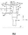
- Figure 2 shows selected portions of the turbine section 28 including a rotor 60 carrying one or more airfoils or blades 61 for rotation about the central axis A.
- like reference numerals designate like elements where appropriate and reference numerals with the addition of one-hundred or multiples thereof designate modified elements that are understood to incorporate the same features and benefits of the corresponding original elements.
- each blade 61 includes a platform 62 and an airfoil section 65 extending in a radial direction R from the platform 62 to a tip 64.
- the airfoil section 65 generally extends in a chordwise direction C between a leading edge 66 and a trailing edge 68.
- a root section 67 of the blade 61 is mounted to the rotor 60, for example.
- the blade 61 can alternatively be integrally formed with the rotor 60, which is sometimes referred to as an integrally bladed rotor (IBR).
- a blade outer air seal (BOAS) 69 is spaced radially outward from the tip 64 of the airfoil section 65.
- a vane 70 is positioned along the engine axis A and adjacent to the blade 61.
- the vane 70 includes an airfoil section 71 extending between an inner platform 72 and an outer platform 73 to define a portion of the core flow path C.
- the turbine section 28 includes multiple blades 61, vanes 70, and blade outer air seals 69 arranged circumferentially about the engine axis A.
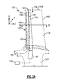
- FIGS 3A and 3B illustrate an exemplary cooling arrangement 176 for a blade 161, such as the one or more blades 61 of Figure 2 .
- a blade 161 such as the one or more blades 61 of Figure 2 .
- the exemplary cooling arrangements discussed in the disclosure primarily refer to a turbine blade, the teachings herein can also be utilized for another portion of the engine 20 such as vane 70 or BOAS 69, for example.
- At least one radial cooling passage 177 (only one shown for illustrative purposes) is provided between pressure and suction sides 174, 175 in a thickness direction T which is generally perpendicular to a chordwise direction C.
- Each radial cooling passage 177 extends from a root section 167 through the platform 162 and toward the tip 164 to communicate coolant to various portions of the blade 161.
- Each radial passage 177 is configured to receive coolant from a coolant source 178 (shown schematically). Coolant sources 178 can include bleed air from an upstream stage of the compressor section 24, bypass air, or a secondary cooling system aboard the aircraft, for example.
- the cooling arrangement 176 includes a feeding cavity 179 (or one of a first cavity and a second cavity) and an impingement cavity 180 (or the other one of the first cavity and the second cavity) coupled by one or more crossover passages 183 within an internal wall 184 (only one feeding cavity 179 and one impingement cavity 180 shown in Figure 3A for illustrative purposes).
- One of the radial passages 177 or another source communicates coolant to the feeding cavity 179.
- the feeding cavity 179 and impingement cavity 180 can be formed in various locations of the blade 161.
- the impingement cavity 180 is bounded by an external wall 181 of the blade 161. As shown, the feeding cavity 179 and/or impingement cavity 180 are located at the leading edge 166. In another example, the feeding cavity 179 and/or the impingement cavity 180 are located at the trailing edge 168 or between the leading and trailing edges 166, 168 (shown in Figure 3B ).
- the airfoil section 165 can include multiple feeding cavities 179 and/or impingement cavities 180 to provide cooling to various portions of the airfoil section 165, as illustrated in Figure 3B .
- the blade 161 can include one or more film cooling holes or passages 194 in fluid communication with one or more of the feeding cavity 179 and/or the impingement cavity 180 to provide film cooling to various surfaces of the blade 161.
- the cooling arrangement 176 includes one or more trip strips 195 (shown in Figure 3B ) extending from a wall of the feeding cavity 179 and/or the impingement cavity 180.
- the trip strips 195 are arranged to interact with coolant communicated in the cavities 179, 180 to provide convective cooling to adjacent portions of the blade 161.
- the trip strips 195 can be arranged at various locations depending on the needs of a particular situation, and arranged at various orientations utilizing any of the techniques discussed herein.
- Figures 4A and 4B illustrate a portion of a casting core 196 having various arrangements corresponding to various feeding and impingement cavities 179, 180 of the cooling arrangement 176, for example.
- the casting core 196 includes a first portion 197 corresponding to the feeding cavity 179 and a second portion 198 corresponding to the impingement cavity 180, for example.
- the first portion 197 corresponds to the impingement cavity 180
- the second portion 198 corresponds to the feeding cavity 179.
- the casting core 196 is provided with one or more crossover connectors 199 (shown in Figure 4B ), which correspond to crossover passages, to connect the first portion 197 and the second portion 198.
- Portions of the casting core 196 can be fabricated by at least two complementary casting dies 202A, 202B (shown in Figure 4B ) utilizing various casting techniques, for example. Although only two casting dies 202 are shown, more than two casting dies can be utilized to form various portions of the casting core 196 including any of the groove arrangements discussed herein.
- the casting dies 202A, 202B form, or otherwise define, one or more parting lines 204 at locations of the casting core 196 where the casting dies 202A, 202B abut each other.
- the parting line 204 defines a reference plane extending generally in the radial and chordwise directions C, R to separate a pressure side 206 and a suction side 207 of the casting core 196.
- the parting line 204 or reference plane can be planar or curvilinear, for example.
- Casting die 202A defines a pull direction P A perpendicular to a corresponding pull plane 208 A
- casting die 202B can define a pull direction P B perpendicular to a corresponding pull plane 208 B (shown in Figure 4B ).
- Surface protrusions 210 extending from one or more cavities of the casting dies 202A, 202B are configured such that one or more grooves 212 (shown in Figure 4A ) corresponding to trip strips 195 are defined in the first portion 197 and/or the second portion 198. As shown, at least some of the grooves 212 are spaced from the parting line 204 to permit removal of material or flash from the casting core 196 at a predetermined keep-out area adjacent the parting line 204.
- the grooves 212 can be arranged relative to the reference plane defined by the parting line 204.
- Each of the grooves 212 defines a respective groove axis 214 (shown in Figure 4A and also indicated at Figure 4B for corresponding surface protrusions 210A).
- a first set of grooves 212A are distributed along a first side 215A (shown in Figure 4B ) of the reference plane defined by parting line 204 such that one or more of the groove axes 214A of the first set of grooves 212A is oriented with respect to a pull direction P of at least one of the casting dies 202A, 202B.
- one or more, or each, of the groove axes 214A of the first set of grooves 212A is parallel to the pull direction P of at least one of the casting dies 202A, 202B, and in yet further examples, one or more, or each, of the groove axes 214A is substantially horizontal or parallel to a reference plane extending in the thickness and chordwise directions T, C. Parallel can be within ⁇ 10 degrees, more narrowly within ⁇ 5 degrees, or evenly more narrowly exactly parallel.
- the first side 215A can correspond to the pressure side 174 and a second side 215B can correspond to the suction side 175 of the blade 161, for example.
- the arrangement of the first set of grooves 212A relative to the parting line 204 reduces a likelihood of backlock of the casting core 196 during separation of the casting dies 202A, 202B, and also reduces the need for additional die pulls and parting lines during formation of the grooves 212, thereby simplifying the fabrication of the casting core 196.
- the arrangement of the first set of grooves 212A can reduce the keep-out areas adjacent the parting line 204, thereby allowing a relatively greater length and improved convective cooling characteristics.
- the groove axis 214A of each of the first set of grooves 212A is parallel to the pull direction P.
- the groove axis 214A of each of the first set of grooves 212A is arranged at a radial angle 216A relative to a localized region of the reference plane defined by the parting line 204 an orientation of the each of the first set of grooves 212A is substantially the same in the spanwise or radial direction R (or first direction).
- the first set of grooves 212A extend a length along the groove axis 214A such that the at least some grooves 212A are substantially straight and are aligned in the pull direction P.
- the first set of grooves 212A are substantially aligned in parallel with a plane extending in the chordwise and thickness directions C, T as illustrated in Figure 4A .
- the first set of grooves 212A can be located on a second side 215B of the reference plane defined by the parting line 204 such that the corresponding trip strips 195 are located adjacent to the pressure side 174 of the blade 161, for example.
- the casting dies 202 can define other grooves 212 in various locations of the casting core 196.
- surface protrusions 210B of the casting dies 202 such as casting die 202A are configured to define a second set of grooves 212B distributed in the spanwise or radial direction R (or first direction) such that each of the second set of grooves 212B defines a second respective groove axis 214B (also indicated at Figure 4B for corresponding surface protrusions 210B) transverse to the pull direction P of at least one of the casting dies 202A, 202B.
- the transverse arrangement of the second set of grooves 212B allows for a greater length and convective cooling characteristics relative to the first set of grooves 212A.
- one or more of the second set of grooves 212B can be connected to one or more of the first set of grooves 212A to increase an overall wetted area and convective cooling characteristics of the corresponding trip strips 195.
- Surface protrusions 210C of the casting dies 202 can be configured to define a third set of grooves 212C distributed on the second side 215B (shown in Figure 4B ) of the reference plane defined by the parting line 204. As shown, the third set of grooves 212C can be arranged such that the groove axis 214C of at least some of third set of grooves 212C is transverse to the pull direction P.
- the third set of grooves 212C can be arranged in a similar manner as the first set of grooves 212A such that the groove axis 214C of at least some of the third set of grooves 212C is oriented with respect to a pull direction P, or parallel to, at least one of the casting dies 202A, 202B.
- grooves 212, corresponding trip strips 195, and casting dies 202 are primarily discussed with respect to a leading edge 166 of a blade 161
- the various arrangements of the grooves 212 and trip strips 195 can be utilized at other locations of the in the airfoil section 165 and/or the platform 162 of the blade 161 and other locations of the engine 20, utilizing any of the techniques discussed herein.
- Figures 5A and 5B illustrates a second embodiment of portions of a casting core 396 for a component.
- the casting core 396 can be utilized in the formation of cooling arrangements for components of the engine 20 such as one of the platforms 62, 72, 73 or the BOAS 69 of Figure 2 , for example.
- the casting core 396 is shown having a generally rectangular profile, which can be contoured with respect to the engine axis A (shown in Figures 1 and 2 ), for example, other configurations can be utilized depending on the needs of a particular situation in view of the teachings herein.
- the casting core 396 includes at least a first portion 397 corresponding to an impingement cavity or a feeding cavity having various arrangements. Portions of the casting core 396 can be fabricated by at least two complementary casting dies 402A, 402B (shown in Figure 5B ) utilizing any of various casting techniques and arrangements disclosed herein.
- the casting dies 402A, 402B form, or otherwise define, one or more parting lines 404.
- Casting die 402A defines a pull direction P A perpendicular to a corresponding pull plane 408 A
- casting die 402B can define a pull direction P B perpendicular to a corresponding pull plane 408 B (shown in Figure 5B ).
- One or more surface protrusions 410 extend from one or more cavities of the casting dies 402A, 402B and are configured such that one or more grooves 412 are formed in the casting core 396 (shown in Figure 5A ) which correspond to one or more trip strips in the component. At least some of the grooves 412 are spaced from the parting line 404.
- the grooves 412 can be arranged relative to the reference plane defined by the parting line 404 utilizing any of the techniques described herein. As shown, a first set of grooves 412A are distributed along a first side 415A of a reference plane defined by the parting line 404 such that one or more of the groove axes 414A of the first set of grooves 412A is oriented with respect to a pull direction P of at least one of the casting dies 402A, 402B.
- a second set of grooves 412B are distributed along a second side 415B of the reference plane defined by the parting line 404 such that one or more of groove axes 414B of the second set of grooves 412B is oriented with respect to a pull direction P of at least one of the casting dies 402A, 402B.
- the groove axis 414 of at least some of the first and/or second set of grooves 412A, 412B is parallel to the pull direction P of at least one of the casting dies 402A, 402B.
- a third set of grooves 412C are distributed along the second side 415B such that the one or more of the groove axes 414C of the third set of grooves 412C is oriented transverse to the pull direction P, and can be connected to one or more of the second set of grooves 412B.
- the core 396 is a wax core formed by dies utilizing the techniques discussed herein, which can be utilized to form one or more pockets 86A, 86B at various locations and orientations in platform 70 or pockets 88 at various locations and orientations in BOAS 69 of Figure 2 .
- the pockets 86A, 86B or 88 can be arranged opposite of the core flow path C and can be configured to receive coolant from various cooling sources including those discussed herein to provide impingement cooling to selected portions of the platform 70 or BOAS 69, for example.
- grooves 412A, 412B are located adjacent to a leading edge 85 of one of the platforms 72, 73 of vane 70, and grooves 412C are located adjacent to a mate face 87 of one of the platforms 72, 73 (shown in Figure 2 ).
- the grooves 412A, 412B are located adjacent to a leading edge 89 of BOAS 69 and grooves 412C are located adjacent to a mate face 90 of BOAS 69 (shown in Figure 2 ).
Landscapes
- Engineering & Computer Science (AREA)
- Mechanical Engineering (AREA)
- General Engineering & Computer Science (AREA)
- Architecture (AREA)
- Turbine Rotor Nozzle Sealing (AREA)
- Molds, Cores, And Manufacturing Methods Thereof (AREA)
Applications Claiming Priority (1)
| Application Number | Priority Date | Filing Date | Title |
|---|---|---|---|
| US14/702,136 US10406596B2 (en) | 2015-05-01 | 2015-05-01 | Core arrangement for turbine engine component |
Publications (2)
| Publication Number | Publication Date |
|---|---|
| EP3088100A1 true EP3088100A1 (fr) | 2016-11-02 |
| EP3088100B1 EP3088100B1 (fr) | 2020-01-01 |
Family
ID=55860773
Family Applications (1)
| Application Number | Title | Priority Date | Filing Date |
|---|---|---|---|
| EP16167665.5A Active EP3088100B1 (fr) | 2015-05-01 | 2016-04-29 | Système de noyau pour composant de moteur à turbine |
Country Status (3)
| Country | Link |
|---|---|
| US (2) | US10406596B2 (fr) |
| EP (1) | EP3088100B1 (fr) |
| SG (1) | SG10201602096YA (fr) |
Cited By (10)
| Publication number | Priority date | Publication date | Assignee | Title |
|---|---|---|---|---|
| EP3521574A1 (fr) * | 2018-02-06 | 2019-08-07 | United Technologies Corporation | Tuile de chemise de chambre de combustion avec trous de refroidissement et son procédé de fabrication |
| EP3690190A1 (fr) * | 2019-01-30 | 2020-08-05 | United Technologies Corporation | Composants de moteur à turbine à gaz dotés de réseaux de bande de déclenchement entrelacés |
| US10830435B2 (en) | 2018-02-06 | 2020-11-10 | Raytheon Technologies Corporation | Diffusing hole for rail effusion |
| US10981217B2 (en) | 2018-11-19 | 2021-04-20 | General Electric Company | Leachable casting core and method of manufacture |
| US11009230B2 (en) | 2018-02-06 | 2021-05-18 | Raytheon Technologies Corporation | Undercut combustor panel rail |
| US11021968B2 (en) | 2018-11-19 | 2021-06-01 | General Electric Company | Reduced cross flow linking cavities and method of casting |
| US11022307B2 (en) | 2018-02-22 | 2021-06-01 | Raytheon Technology Corporation | Gas turbine combustor heat shield panel having multi-direction hole for rail effusion cooling |
| US11346230B1 (en) | 2019-02-04 | 2022-05-31 | Raytheon Technologies Corporation | Turbine blade cooling hole arrangement |
| US11788416B2 (en) | 2019-01-30 | 2023-10-17 | Rtx Corporation | Gas turbine engine components having interlaced trip strip arrays |
| US11998974B2 (en) | 2022-08-30 | 2024-06-04 | General Electric Company | Casting core for a cast engine component |
Families Citing this family (10)
| Publication number | Priority date | Publication date | Assignee | Title |
|---|---|---|---|---|
| JP5567180B1 (ja) * | 2013-05-20 | 2014-08-06 | 川崎重工業株式会社 | タービン翼の冷却構造 |
| US10605090B2 (en) * | 2016-05-12 | 2020-03-31 | General Electric Company | Intermediate central passage spanning outer walls aft of airfoil leading edge passage |
| US11098595B2 (en) * | 2017-05-02 | 2021-08-24 | Raytheon Technologies Corporation | Airfoil for gas turbine engine |
| US10570748B2 (en) * | 2018-01-10 | 2020-02-25 | United Technologies Corporation | Impingement cooling arrangement for airfoils |
| GB2571549A (en) * | 2018-03-01 | 2019-09-04 | Rolls Royce Plc | A core for an investment casting process |
| US11098591B1 (en) | 2019-02-04 | 2021-08-24 | Raytheon Technologies Corporation | Turbine blade with contoured fillet |
| US11143037B1 (en) | 2019-02-04 | 2021-10-12 | Raytheon Technologies Corporation | Turbine blade cooling hole arrangement |
| KR102161765B1 (ko) * | 2019-02-22 | 2020-10-05 | 두산중공업 주식회사 | 터빈용 에어포일, 이를 포함하는 터빈 |
| US11952911B2 (en) * | 2019-11-14 | 2024-04-09 | Rtx Corporation | Airfoil with connecting rib |
| EP4534800A3 (fr) * | 2023-08-16 | 2025-08-20 | RTX Corporation | Aube de turbine avec turbulateurs dans les passages de refroidissement de la peau |
Citations (3)
| Publication number | Priority date | Publication date | Assignee | Title |
|---|---|---|---|---|
| EP0758932A1 (fr) * | 1994-04-19 | 1997-02-26 | United Technologies Corporation | Refroidissement d'une aube de turbine a gaz |
| EP1543896A2 (fr) * | 2003-12-19 | 2005-06-22 | United Technologies Corporation | Noyaux pour la coulée de précision |
| WO2014159589A1 (fr) * | 2013-03-14 | 2014-10-02 | United Technologies Corporation | Refroidissement d'un composant d'un moteur à turbine à gaz avec des bandes de déclenchement en regard imbriquées |
Family Cites Families (20)
| Publication number | Priority date | Publication date | Assignee | Title |
|---|---|---|---|---|
| US4353679A (en) * | 1976-07-29 | 1982-10-12 | General Electric Company | Fluid-cooled element |
| US4627480A (en) * | 1983-11-07 | 1986-12-09 | General Electric Company | Angled turbulence promoter |
| US5232343A (en) | 1984-05-24 | 1993-08-03 | General Electric Company | Turbine blade |
| US5052889A (en) * | 1990-05-17 | 1991-10-01 | Pratt & Whintey Canada | Offset ribs for heat transfer surface |
| JP3006174B2 (ja) * | 1991-07-04 | 2000-02-07 | 株式会社日立製作所 | 内部に冷却通路を有する部材 |
| US5472316A (en) | 1994-09-19 | 1995-12-05 | General Electric Company | Enhanced cooling apparatus for gas turbine engine airfoils |
| EP0892149B1 (fr) | 1997-07-14 | 2003-01-22 | ALSTOM (Switzerland) Ltd | Système de refroidissement pour le bord d'attac d'une aube creuse pour turbine à gaz |
| US6340047B1 (en) * | 1999-03-22 | 2002-01-22 | General Electric Company | Core tied cast airfoil |
| US6884036B2 (en) | 2003-04-15 | 2005-04-26 | General Electric Company | Complementary cooled turbine nozzle |
| US7216689B2 (en) * | 2004-06-14 | 2007-05-15 | United Technologies Corporation | Investment casting |
| US20070297916A1 (en) | 2006-06-22 | 2007-12-27 | United Technologies Corporation | Leading edge cooling using wrapped staggered-chevron trip strips |
| US8757974B2 (en) | 2007-01-11 | 2014-06-24 | United Technologies Corporation | Cooling circuit flow path for a turbine section airfoil |
| US8083485B2 (en) * | 2007-08-15 | 2011-12-27 | United Technologies Corporation | Angled tripped airfoil peanut cavity |
| US8376706B2 (en) | 2007-09-28 | 2013-02-19 | General Electric Company | Turbine airfoil concave cooling passage using dual-swirl flow mechanism and method |
| GB0909255D0 (en) * | 2009-06-01 | 2009-07-15 | Rolls Royce Plc | Cooling arrangements |
| US8961133B2 (en) | 2010-12-28 | 2015-02-24 | Rolls-Royce North American Technologies, Inc. | Gas turbine engine and cooled airfoil |
| US9238970B2 (en) * | 2011-09-19 | 2016-01-19 | United Technologies Corporation | Blade outer air seal assembly leading edge core configuration |
| WO2015023338A2 (fr) | 2013-05-24 | 2015-02-19 | United Technologies Corporation | Composant de moteur à turbine à gaz possédant des bandes de déclenchement |
| US9359902B2 (en) | 2013-06-28 | 2016-06-07 | Siemens Energy, Inc. | Turbine airfoil with ambient cooling system |
| GB201314222D0 (en) | 2013-08-08 | 2013-09-25 | Rolls Royce Plc | Aerofoil |
-
2015
- 2015-05-01 US US14/702,136 patent/US10406596B2/en active Active
-
2016
- 2016-03-17 SG SG10201602096YA patent/SG10201602096YA/en unknown
- 2016-04-29 EP EP16167665.5A patent/EP3088100B1/fr active Active
-
2019
- 2019-07-24 US US16/520,911 patent/US11148191B2/en active Active
Patent Citations (3)
| Publication number | Priority date | Publication date | Assignee | Title |
|---|---|---|---|---|
| EP0758932A1 (fr) * | 1994-04-19 | 1997-02-26 | United Technologies Corporation | Refroidissement d'une aube de turbine a gaz |
| EP1543896A2 (fr) * | 2003-12-19 | 2005-06-22 | United Technologies Corporation | Noyaux pour la coulée de précision |
| WO2014159589A1 (fr) * | 2013-03-14 | 2014-10-02 | United Technologies Corporation | Refroidissement d'un composant d'un moteur à turbine à gaz avec des bandes de déclenchement en regard imbriquées |
Cited By (16)
| Publication number | Priority date | Publication date | Assignee | Title |
|---|---|---|---|---|
| US11009230B2 (en) | 2018-02-06 | 2021-05-18 | Raytheon Technologies Corporation | Undercut combustor panel rail |
| EP3521574A1 (fr) * | 2018-02-06 | 2019-08-07 | United Technologies Corporation | Tuile de chemise de chambre de combustion avec trous de refroidissement et son procédé de fabrication |
| US10830435B2 (en) | 2018-02-06 | 2020-11-10 | Raytheon Technologies Corporation | Diffusing hole for rail effusion |
| US11248791B2 (en) | 2018-02-06 | 2022-02-15 | Raytheon Technologies Corporation | Pull-plane effusion combustor panel |
| US20230076312A1 (en) * | 2018-02-22 | 2023-03-09 | Raytheon Technologies Corporation | Multi-direction hole for rail effusion |
| US11022307B2 (en) | 2018-02-22 | 2021-06-01 | Raytheon Technology Corporation | Gas turbine combustor heat shield panel having multi-direction hole for rail effusion cooling |
| US11359812B2 (en) | 2018-02-22 | 2022-06-14 | Raytheon Technologies Corporation | Multi-direction hole for rail effusion |
| US11725816B2 (en) | 2018-02-22 | 2023-08-15 | Raytheon Technologies Corporation | Multi-direction hole for rail effusion |
| US11021968B2 (en) | 2018-11-19 | 2021-06-01 | General Electric Company | Reduced cross flow linking cavities and method of casting |
| US10981217B2 (en) | 2018-11-19 | 2021-04-20 | General Electric Company | Leachable casting core and method of manufacture |
| US11389862B2 (en) | 2018-11-19 | 2022-07-19 | General Electric Company | Leachable casting core and method of manufacture |
| US11408290B2 (en) | 2018-11-19 | 2022-08-09 | General Electric Company | Reduced cross flow linking cavities and method of casting |
| EP3690190A1 (fr) * | 2019-01-30 | 2020-08-05 | United Technologies Corporation | Composants de moteur à turbine à gaz dotés de réseaux de bande de déclenchement entrelacés |
| US11788416B2 (en) | 2019-01-30 | 2023-10-17 | Rtx Corporation | Gas turbine engine components having interlaced trip strip arrays |
| US11346230B1 (en) | 2019-02-04 | 2022-05-31 | Raytheon Technologies Corporation | Turbine blade cooling hole arrangement |
| US11998974B2 (en) | 2022-08-30 | 2024-06-04 | General Electric Company | Casting core for a cast engine component |
Also Published As
| Publication number | Publication date |
|---|---|
| EP3088100B1 (fr) | 2020-01-01 |
| US10406596B2 (en) | 2019-09-10 |
| US20190344334A1 (en) | 2019-11-14 |
| US20160319674A1 (en) | 2016-11-03 |
| SG10201602096YA (en) | 2016-12-29 |
| US11148191B2 (en) | 2021-10-19 |
Similar Documents
| Publication | Publication Date | Title |
|---|---|---|
| US11148191B2 (en) | Core arrangement for turbine engine component | |
| US10253635B2 (en) | Blade tip cooling arrangement | |
| US10145246B2 (en) | Staggered crossovers for airfoils | |
| EP3009599A1 (fr) | Component de turbine à gaz avec un refroidissement par film fluide. | |
| US10975705B2 (en) | Gas turbine engine airfoil with wishbone baffle cooling scheme | |
| US10041358B2 (en) | Gas turbine engine blade squealer pockets | |
| EP3444436B1 (fr) | Agencement de refroidissement directionnel destiné à des aubes de turbine | |
| US20210062667A1 (en) | Seal arrangement for turbine engine component | |
| EP3342982B1 (fr) | Passages de croisement inclinés pour les cavités d'aube internes | |
| US11970954B2 (en) | Airfoil with rib having connector arms | |
| EP2993304B1 (fr) | Composant de moteur à turbine à gaz avec trou formant un film de refroidissement | |
| EP2998511B1 (fr) | Canal de refroidissement avec des caractéristiques de surface | |
| EP3009600A1 (fr) | Aube de turbine à bout refroidi de moteur à turbine à gaz | |
| EP3059391A1 (fr) | Refroidissement de pale de turbine à gaz à l'aide d'une aube de stator amont | |
| US10570748B2 (en) | Impingement cooling arrangement for airfoils | |
| US20150300201A1 (en) | Method of reducing manufacturing variation related to blocked cooling holes | |
| EP3061913B1 (fr) | Configuration de refroidissement d'aube de moteur à turbine à gaz avec séparateurs de gradient de pression | |
| EP2977557B1 (fr) | Structure d'aube refroidie et procédé de refroidissement associé | |
| EP2942486B1 (fr) | Configuration de passage de refroidissement de profil aérodynamique de turbine à gaz |
Legal Events
| Date | Code | Title | Description |
|---|---|---|---|
| PUAI | Public reference made under article 153(3) epc to a published international application that has entered the european phase |
Free format text: ORIGINAL CODE: 0009012 |
|
| AK | Designated contracting states |
Kind code of ref document: A1 Designated state(s): AL AT BE BG CH CY CZ DE DK EE ES FI FR GB GR HR HU IE IS IT LI LT LU LV MC MK MT NL NO PL PT RO RS SE SI SK SM TR |
|
| AX | Request for extension of the european patent |
Extension state: BA ME |
|
| 17P | Request for examination filed |
Effective date: 20170502 |
|
| RBV | Designated contracting states (corrected) |
Designated state(s): AL AT BE BG CH CY CZ DE DK EE ES FI FR GB GR HR HU IE IS IT LI LT LU LV MC MK MT NL NO PL PT RO RS SE SI SK SM TR |
|
| STAA | Information on the status of an ep patent application or granted ep patent |
Free format text: STATUS: REQUEST FOR EXAMINATION WAS MADE |
|
| STAA | Information on the status of an ep patent application or granted ep patent |
Free format text: STATUS: EXAMINATION IS IN PROGRESS |
|
| 17Q | First examination report despatched |
Effective date: 20180928 |
|
| GRAP | Despatch of communication of intention to grant a patent |
Free format text: ORIGINAL CODE: EPIDOSNIGR1 |
|
| STAA | Information on the status of an ep patent application or granted ep patent |
Free format text: STATUS: GRANT OF PATENT IS INTENDED |
|
| RIC1 | Information provided on ipc code assigned before grant |
Ipc: F01D 5/18 20060101ALI20190627BHEP Ipc: B22D 25/02 20060101ALI20190627BHEP Ipc: B22D 17/00 20060101ALI20190627BHEP Ipc: F01D 5/14 20060101ALI20190627BHEP Ipc: B22C 9/06 20060101ALI20190627BHEP Ipc: B22C 9/10 20060101AFI20190627BHEP Ipc: B22D 15/00 20060101ALI20190627BHEP |
|
| INTG | Intention to grant announced |
Effective date: 20190716 |
|
| GRAS | Grant fee paid |
Free format text: ORIGINAL CODE: EPIDOSNIGR3 |
|
| GRAA | (expected) grant |
Free format text: ORIGINAL CODE: 0009210 |
|
| STAA | Information on the status of an ep patent application or granted ep patent |
Free format text: STATUS: THE PATENT HAS BEEN GRANTED |
|
| AK | Designated contracting states |
Kind code of ref document: B1 Designated state(s): AL AT BE BG CH CY CZ DE DK EE ES FI FR GB GR HR HU IE IS IT LI LT LU LV MC MK MT NL NO PL PT RO RS SE SI SK SM TR |
|
| REG | Reference to a national code |
Ref country code: GB Ref legal event code: FG4D |
|
| REG | Reference to a national code |
Ref country code: CH Ref legal event code: EP Ref country code: AT Ref legal event code: REF Ref document number: 1219141 Country of ref document: AT Kind code of ref document: T Effective date: 20200115 |
|
| REG | Reference to a national code |
Ref country code: DE Ref legal event code: R096 Ref document number: 602016027153 Country of ref document: DE |
|
| REG | Reference to a national code |
Ref country code: IE Ref legal event code: FG4D |
|
| REG | Reference to a national code |
Ref country code: NL Ref legal event code: MP Effective date: 20200101 |
|
| REG | Reference to a national code |
Ref country code: LT Ref legal event code: MG4D |
|
| PG25 | Lapsed in a contracting state [announced via postgrant information from national office to epo] |
Ref country code: LT Free format text: LAPSE BECAUSE OF FAILURE TO SUBMIT A TRANSLATION OF THE DESCRIPTION OR TO PAY THE FEE WITHIN THE PRESCRIBED TIME-LIMIT Effective date: 20200101 Ref country code: RS Free format text: LAPSE BECAUSE OF FAILURE TO SUBMIT A TRANSLATION OF THE DESCRIPTION OR TO PAY THE FEE WITHIN THE PRESCRIBED TIME-LIMIT Effective date: 20200101 Ref country code: FI Free format text: LAPSE BECAUSE OF FAILURE TO SUBMIT A TRANSLATION OF THE DESCRIPTION OR TO PAY THE FEE WITHIN THE PRESCRIBED TIME-LIMIT Effective date: 20200101 Ref country code: NO Free format text: LAPSE BECAUSE OF FAILURE TO SUBMIT A TRANSLATION OF THE DESCRIPTION OR TO PAY THE FEE WITHIN THE PRESCRIBED TIME-LIMIT Effective date: 20200401 Ref country code: PT Free format text: LAPSE BECAUSE OF FAILURE TO SUBMIT A TRANSLATION OF THE DESCRIPTION OR TO PAY THE FEE WITHIN THE PRESCRIBED TIME-LIMIT Effective date: 20200527 Ref country code: CZ Free format text: LAPSE BECAUSE OF FAILURE TO SUBMIT A TRANSLATION OF THE DESCRIPTION OR TO PAY THE FEE WITHIN THE PRESCRIBED TIME-LIMIT Effective date: 20200101 Ref country code: NL Free format text: LAPSE BECAUSE OF FAILURE TO SUBMIT A TRANSLATION OF THE DESCRIPTION OR TO PAY THE FEE WITHIN THE PRESCRIBED TIME-LIMIT Effective date: 20200101 |
|
| PG25 | Lapsed in a contracting state [announced via postgrant information from national office to epo] |
Ref country code: HR Free format text: LAPSE BECAUSE OF FAILURE TO SUBMIT A TRANSLATION OF THE DESCRIPTION OR TO PAY THE FEE WITHIN THE PRESCRIBED TIME-LIMIT Effective date: 20200101 Ref country code: BG Free format text: LAPSE BECAUSE OF FAILURE TO SUBMIT A TRANSLATION OF THE DESCRIPTION OR TO PAY THE FEE WITHIN THE PRESCRIBED TIME-LIMIT Effective date: 20200401 Ref country code: GR Free format text: LAPSE BECAUSE OF FAILURE TO SUBMIT A TRANSLATION OF THE DESCRIPTION OR TO PAY THE FEE WITHIN THE PRESCRIBED TIME-LIMIT Effective date: 20200402 Ref country code: SE Free format text: LAPSE BECAUSE OF FAILURE TO SUBMIT A TRANSLATION OF THE DESCRIPTION OR TO PAY THE FEE WITHIN THE PRESCRIBED TIME-LIMIT Effective date: 20200101 Ref country code: LV Free format text: LAPSE BECAUSE OF FAILURE TO SUBMIT A TRANSLATION OF THE DESCRIPTION OR TO PAY THE FEE WITHIN THE PRESCRIBED TIME-LIMIT Effective date: 20200101 Ref country code: IS Free format text: LAPSE BECAUSE OF FAILURE TO SUBMIT A TRANSLATION OF THE DESCRIPTION OR TO PAY THE FEE WITHIN THE PRESCRIBED TIME-LIMIT Effective date: 20200501 |
|
| REG | Reference to a national code |
Ref country code: DE Ref legal event code: R097 Ref document number: 602016027153 Country of ref document: DE |
|
| PG25 | Lapsed in a contracting state [announced via postgrant information from national office to epo] |
Ref country code: SK Free format text: LAPSE BECAUSE OF FAILURE TO SUBMIT A TRANSLATION OF THE DESCRIPTION OR TO PAY THE FEE WITHIN THE PRESCRIBED TIME-LIMIT Effective date: 20200101 Ref country code: RO Free format text: LAPSE BECAUSE OF FAILURE TO SUBMIT A TRANSLATION OF THE DESCRIPTION OR TO PAY THE FEE WITHIN THE PRESCRIBED TIME-LIMIT Effective date: 20200101 Ref country code: ES Free format text: LAPSE BECAUSE OF FAILURE TO SUBMIT A TRANSLATION OF THE DESCRIPTION OR TO PAY THE FEE WITHIN THE PRESCRIBED TIME-LIMIT Effective date: 20200101 Ref country code: DK Free format text: LAPSE BECAUSE OF FAILURE TO SUBMIT A TRANSLATION OF THE DESCRIPTION OR TO PAY THE FEE WITHIN THE PRESCRIBED TIME-LIMIT Effective date: 20200101 Ref country code: SM Free format text: LAPSE BECAUSE OF FAILURE TO SUBMIT A TRANSLATION OF THE DESCRIPTION OR TO PAY THE FEE WITHIN THE PRESCRIBED TIME-LIMIT Effective date: 20200101 Ref country code: EE Free format text: LAPSE BECAUSE OF FAILURE TO SUBMIT A TRANSLATION OF THE DESCRIPTION OR TO PAY THE FEE WITHIN THE PRESCRIBED TIME-LIMIT Effective date: 20200101 |
|
| PLBE | No opposition filed within time limit |
Free format text: ORIGINAL CODE: 0009261 |
|
| STAA | Information on the status of an ep patent application or granted ep patent |
Free format text: STATUS: NO OPPOSITION FILED WITHIN TIME LIMIT |
|
| REG | Reference to a national code |
Ref country code: AT Ref legal event code: MK05 Ref document number: 1219141 Country of ref document: AT Kind code of ref document: T Effective date: 20200101 |
|
| PG25 | Lapsed in a contracting state [announced via postgrant information from national office to epo] |
Ref country code: MC Free format text: LAPSE BECAUSE OF FAILURE TO SUBMIT A TRANSLATION OF THE DESCRIPTION OR TO PAY THE FEE WITHIN THE PRESCRIBED TIME-LIMIT Effective date: 20200101 |
|
| REG | Reference to a national code |
Ref country code: CH Ref legal event code: PL |
|
| 26N | No opposition filed |
Effective date: 20201002 |
|
| PG25 | Lapsed in a contracting state [announced via postgrant information from national office to epo] |
Ref country code: AT Free format text: LAPSE BECAUSE OF FAILURE TO SUBMIT A TRANSLATION OF THE DESCRIPTION OR TO PAY THE FEE WITHIN THE PRESCRIBED TIME-LIMIT Effective date: 20200101 Ref country code: LI Free format text: LAPSE BECAUSE OF NON-PAYMENT OF DUE FEES Effective date: 20200430 Ref country code: CH Free format text: LAPSE BECAUSE OF NON-PAYMENT OF DUE FEES Effective date: 20200430 Ref country code: IT Free format text: LAPSE BECAUSE OF FAILURE TO SUBMIT A TRANSLATION OF THE DESCRIPTION OR TO PAY THE FEE WITHIN THE PRESCRIBED TIME-LIMIT Effective date: 20200101 Ref country code: LU Free format text: LAPSE BECAUSE OF NON-PAYMENT OF DUE FEES Effective date: 20200429 |
|
| REG | Reference to a national code |
Ref country code: BE Ref legal event code: MM Effective date: 20200430 |
|
| PG25 | Lapsed in a contracting state [announced via postgrant information from national office to epo] |
Ref country code: PL Free format text: LAPSE BECAUSE OF FAILURE TO SUBMIT A TRANSLATION OF THE DESCRIPTION OR TO PAY THE FEE WITHIN THE PRESCRIBED TIME-LIMIT Effective date: 20200101 Ref country code: SI Free format text: LAPSE BECAUSE OF FAILURE TO SUBMIT A TRANSLATION OF THE DESCRIPTION OR TO PAY THE FEE WITHIN THE PRESCRIBED TIME-LIMIT Effective date: 20200101 Ref country code: BE Free format text: LAPSE BECAUSE OF NON-PAYMENT OF DUE FEES Effective date: 20200430 |
|
| PG25 | Lapsed in a contracting state [announced via postgrant information from national office to epo] |
Ref country code: IE Free format text: LAPSE BECAUSE OF NON-PAYMENT OF DUE FEES Effective date: 20200429 |
|
| PG25 | Lapsed in a contracting state [announced via postgrant information from national office to epo] |
Ref country code: TR Free format text: LAPSE BECAUSE OF FAILURE TO SUBMIT A TRANSLATION OF THE DESCRIPTION OR TO PAY THE FEE WITHIN THE PRESCRIBED TIME-LIMIT Effective date: 20200101 Ref country code: MT Free format text: LAPSE BECAUSE OF FAILURE TO SUBMIT A TRANSLATION OF THE DESCRIPTION OR TO PAY THE FEE WITHIN THE PRESCRIBED TIME-LIMIT Effective date: 20200101 Ref country code: CY Free format text: LAPSE BECAUSE OF FAILURE TO SUBMIT A TRANSLATION OF THE DESCRIPTION OR TO PAY THE FEE WITHIN THE PRESCRIBED TIME-LIMIT Effective date: 20200101 |
|
| PG25 | Lapsed in a contracting state [announced via postgrant information from national office to epo] |
Ref country code: MK Free format text: LAPSE BECAUSE OF FAILURE TO SUBMIT A TRANSLATION OF THE DESCRIPTION OR TO PAY THE FEE WITHIN THE PRESCRIBED TIME-LIMIT Effective date: 20200101 Ref country code: AL Free format text: LAPSE BECAUSE OF FAILURE TO SUBMIT A TRANSLATION OF THE DESCRIPTION OR TO PAY THE FEE WITHIN THE PRESCRIBED TIME-LIMIT Effective date: 20200101 |
|
| REG | Reference to a national code |
Ref country code: DE Ref legal event code: R081 Ref document number: 602016027153 Country of ref document: DE Owner name: RAYTHEON TECHNOLOGIES CORPORATION (N.D.GES.D.S, US Free format text: FORMER OWNER: UNITED TECHNOLOGIES CORPORATION, FARMINGTON, CONN., US Ref country code: DE Ref legal event code: R081 Ref document number: 602016027153 Country of ref document: DE Owner name: RTX CORPORATION (N.D.GES.D. STAATES DELAWARE),, US Free format text: FORMER OWNER: UNITED TECHNOLOGIES CORPORATION, FARMINGTON, CONN., US |
|
| P01 | Opt-out of the competence of the unified patent court (upc) registered |
Effective date: 20230520 |
|
| PGFP | Annual fee paid to national office [announced via postgrant information from national office to epo] |
Ref country code: DE Payment date: 20250319 Year of fee payment: 10 |
|
| REG | Reference to a national code |
Ref country code: DE Ref legal event code: R081 Ref document number: 602016027153 Country of ref document: DE Owner name: RTX CORPORATION (N.D.GES.D. STAATES DELAWARE),, US Free format text: FORMER OWNER: RAYTHEON TECHNOLOGIES CORPORATION (N.D.GES.D.STAATES DELAWARE), ARLINGTON, VA, US |
|
| PGFP | Annual fee paid to national office [announced via postgrant information from national office to epo] |
Ref country code: GB Payment date: 20260319 Year of fee payment: 11 |
|
| PGFP | Annual fee paid to national office [announced via postgrant information from national office to epo] |
Ref country code: FR Payment date: 20260319 Year of fee payment: 11 |