EP3088200B1 - Machine de marquage au laser, procédé de marquage par laser et système de marquage au laser - Google Patents
Machine de marquage au laser, procédé de marquage par laser et système de marquage au laser Download PDFInfo
- Publication number
- EP3088200B1 EP3088200B1 EP15187761.0A EP15187761A EP3088200B1 EP 3088200 B1 EP3088200 B1 EP 3088200B1 EP 15187761 A EP15187761 A EP 15187761A EP 3088200 B1 EP3088200 B1 EP 3088200B1
- Authority
- EP
- European Patent Office
- Prior art keywords
- pixel dot
- main board
- galvanometer
- control main
- laser
- Prior art date
- Legal status (The legal status is an assumption and is not a legal conclusion. Google has not performed a legal analysis and makes no representation as to the accuracy of the status listed.)
- Active
Links
Images


Classifications
-
- B—PERFORMING OPERATIONS; TRANSPORTING
- B41—PRINTING; LINING MACHINES; TYPEWRITERS; STAMPS
- B41J—TYPEWRITERS; SELECTIVE PRINTING MECHANISMS, i.e. MECHANISMS PRINTING OTHERWISE THAN FROM A FORME; CORRECTION OF TYPOGRAPHICAL ERRORS
- B41J2/00—Typewriters or selective printing mechanisms characterised by the printing or marking process for which they are designed
- B41J2/435—Typewriters or selective printing mechanisms characterised by the printing or marking process for which they are designed characterised by selective application of radiation to a printing material or impression-transfer material
- B41J2/47—Typewriters or selective printing mechanisms characterised by the printing or marking process for which they are designed characterised by selective application of radiation to a printing material or impression-transfer material using the combination of scanning and modulation of light
-
- B—PERFORMING OPERATIONS; TRANSPORTING
- B23—MACHINE TOOLS; METAL-WORKING NOT OTHERWISE PROVIDED FOR
- B23K—SOLDERING OR UNSOLDERING; WELDING; CLADDING OR PLATING BY SOLDERING OR WELDING; CUTTING BY APPLYING HEAT LOCALLY, e.g. FLAME CUTTING; WORKING BY LASER BEAM
- B23K26/00—Working by laser beam, e.g. welding, cutting or boring
- B23K26/02—Positioning or observing the workpiece, e.g. with respect to the point of impact; Aligning, aiming or focusing the laser beam
- B23K26/06—Shaping the laser beam, e.g. by masks or multi-focusing
- B23K26/062—Shaping the laser beam, e.g. by masks or multi-focusing by direct control of the laser beam
- B23K26/0626—Energy control of the laser beam
-
- B—PERFORMING OPERATIONS; TRANSPORTING
- B23—MACHINE TOOLS; METAL-WORKING NOT OTHERWISE PROVIDED FOR
- B23K—SOLDERING OR UNSOLDERING; WELDING; CLADDING OR PLATING BY SOLDERING OR WELDING; CUTTING BY APPLYING HEAT LOCALLY, e.g. FLAME CUTTING; WORKING BY LASER BEAM
- B23K26/00—Working by laser beam, e.g. welding, cutting or boring
- B23K26/08—Devices involving relative movement between laser beam and workpiece
- B23K26/082—Scanning systems, i.e. devices involving movement of the laser beam relative to the laser head
-
- B—PERFORMING OPERATIONS; TRANSPORTING
- B23—MACHINE TOOLS; METAL-WORKING NOT OTHERWISE PROVIDED FOR
- B23K—SOLDERING OR UNSOLDERING; WELDING; CLADDING OR PLATING BY SOLDERING OR WELDING; CUTTING BY APPLYING HEAT LOCALLY, e.g. FLAME CUTTING; WORKING BY LASER BEAM
- B23K26/00—Working by laser beam, e.g. welding, cutting or boring
- B23K26/352—Working by laser beam, e.g. welding, cutting or boring for surface treatment
- B23K26/354—Working by laser beam, e.g. welding, cutting or boring for surface treatment by melting
-
- B—PERFORMING OPERATIONS; TRANSPORTING
- B23—MACHINE TOOLS; METAL-WORKING NOT OTHERWISE PROVIDED FOR
- B23K—SOLDERING OR UNSOLDERING; WELDING; CLADDING OR PLATING BY SOLDERING OR WELDING; CUTTING BY APPLYING HEAT LOCALLY, e.g. FLAME CUTTING; WORKING BY LASER BEAM
- B23K26/00—Working by laser beam, e.g. welding, cutting or boring
- B23K26/36—Removing material
- B23K26/361—Removing material for deburring or mechanical trimming
-
- B—PERFORMING OPERATIONS; TRANSPORTING
- B41—PRINTING; LINING MACHINES; TYPEWRITERS; STAMPS
- B41M—PRINTING, DUPLICATING, MARKING, OR COPYING PROCESSES; COLOUR PRINTING
- B41M5/00—Duplicating or marking methods; Sheet materials for use therein
- B41M5/24—Ablative recording, e.g. by burning marks; Spark recording
Definitions
- the present disclosure relates to the technical field of laser marking and, more particularly, to a laser marking method, a laser marking machine, and laser marking system.
- the features of the preamble of the independent claims are known from US 2010/128102 A1 .
- Related technologies are known from US 2009/243155 A1 , DE 197 07 003 A1 , US 8 585 956 B1 , DE 103 39 472 A1 and US 2012/212564 A1 .
- Laser marking is capable of marking characters, symbols and patterns and the like.
- Laser marking is a marking method using high power density laser to irradiate a portion of work piece to gasify surface material or generate chemistry reaction of colour change, thusly leaving a permanent mark.
- marking software may keep configured pixels according to resolution settings of an operator and perform a gray scale calculation according to the three sub-pixels of red, green and blue, thusly obtaining a gray scale value of each pixel.
- the gray scale difference of an image may be presented by a number of marking points per unit area, that is, the gray scale may be presented dependently on a density of marking points. Since the unit area is too small to be detected by naked eyes, only continuous change in pictures may be felt.
- the marking control is separate from the laser control. In the laser control, a segment control is employed, which is coarse, and not accurate enough to be used in the control of marking points, such that the marking resolution is not high enough and the marking efficiency is low.
- a technical problem to be solved in the embodiment of the disclosure is to provide a laser marking method which could separately control the coordinate and the output power of the marking point, and the accurate match between material to be marked and output power of the laser marking machine, to achieve accurate marking.
- the present invention is defined in the independent claims.
- FIG. 1 shows a block diagram of a commonly-used marking machine.
- the commonly-used marking machine includes: CPU/marking software, a control main board, optical paths and galvanometer parts.
- the CPU/marking software is mainly used to process and edit graphics (such as bitmap, vector graphic, text, QR code and the like), and to transform the graphics to marking instructions which could be recognizable by the control main board according to settings and marking conditions of an operator.
- the marking instructions are action splits when the marking machine is marking. Each instruction is one action of the marking machine. Once the instructions are generated, they are packaged to a communication packet of an agreement protocol and transmitted to the control main board.
- the control main board receives the marking instructions from CPU, stores and parses the instructions, and then control operations of back-end optical paths and a galvanometer according to parsed data. Laser moves at a relatively uniform-speed on a plane through a galvanometer. In this manner, marking may be performed on an object to be marked.
- FIG. 2 it shows representations of the gray scale in an existing laser marking machine. As it is shown, the unit area that is all covered by engraving would have the largest gray scale value, while the unit area that has not been engraved at all would have the smallest gray scale value.
- the control main board may control the laser and the galvanometer to cooperate to engrave the areas according to the parsed instructions.
- the representation of gray scale difference may be realized by the existing method, but there are following disadvantages:
- One of main conceptions of the embodiment of the disclosure is to separately control an output power of each target image pixel (marking point), and to transform the target image pixels having different gray scales to the marking points having different powers.
- FIG. 3 it shows a flow chat of a laser marking method according to an example not covered by the present invention, wherein a laser marking machine is used to mark.
- the laser marking machine includes: a control main board, a laser device and a galvanometer, the laser device and the galvanometer being connected to the control main board, respectively; the galvanometer being configured to move at a predetermined moving speed on the basis of coordinate of target image pixel dot; and the laser device being configured to output laser; the method may particularly comprise steps of:
- the method may further include:
- the disclosure discloses a new way to represent gray scale, in which marking depth may be controlled by marking power, and marking gray scale is controlled by the marking depth.
- marking depth may be controlled by marking power
- marking gray scale is controlled by the marking depth.
- the marking process is to transform pixels of the image having different gray scales to the marking points having different powers.
- FIG. 4 shows representations of the gray scale according to the embodiment of the disclosure.
- the image to be marked is transformed to the gray scale image which may be specifically customized according to the resolution required by the user.
- the resolution is the number of dots constituting the gray scale image.
- a resolution of 1024 x 768 means that there are 1024 dots on a horizontal coordinate of the gray scale image and 768 dots on a longitudinal coordinate.
- a gray scale image having a predetermined number of dots may be obtained.
- the transformation of the gray scale value for each dot may be calculated by a brightness value of pixel dot in the original image.
- the brightness value refers to a value of red, green and blue sub-pixels in the image.
- the gray scale value is transformed to a power value of 0-100.
- three sub-pixels of bitmap are transformed to the pixel coordinate and the power value of each dot.
- FIG. 5 it is a schematic diagram showing linear relationship between the pump current and the laser power in the disclosure.
- this linear range may be learned and the coefficient K can be determined.
- the marking software may transform the bitmap to a plurality of pixel dots with different gray scales according to the settings of resolution and the brightness value of each pixel dot in the original image. Once the resolution is determined, the distance between dots may be determined. Once marking brightness is determined, an absolute gray scale of each dot may be determined. As a result, power value and absolute coordinate of each engraving point may be determined.
- the marking solution in the disclosure mainly includes three elements: galvanometer speed, absolute coordinate of each dot and marking power of each dot.
- the marking machine may control uniform movement of the galvanometer at a configured speed. After the galvanometer reaches an absolute coordinate of a certain dot, the marking may be performed at the appropriate power corresponding to this dot.
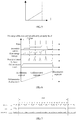
- FIG. 6 it is a schematic diagram showing the control of the laser power according to the embodiment of the disclosure.
- FIG. 6 shows relation among parameters such as the pulse, the pump current, the fibre energy storage, the galvanometer speed and the galvanometer displacement.
- laser period refers to a timing sequence main line connecting the laser device and the galvanometer in the disclosure.
- the laser period refers to a time period of "updating pump current-work fibre storing energy-releasing laser".
- the laser device may include: a pump, a work fibre connected to the pump and an output switch connected to the work fibre.
- the output switch may be an acoustic control switch.
- the work fibre would receive the current output from the pump and start the fibre energy storage.
- the control main board would transmit ON instruction to the acoustic control switch, and the acoustic control switch would switch on upon the receipt of the instruction and output the laser stored in the work fibre.
- the laser period refers to a time period of "moving the galvanometer to a coordinate of a marking point to mark".
- control main board is merely conscious of whether the location command is completely transmitted without obtaining whether the galvanometer has executed.
- Step 303 includes sub-steps of:
- the predetermined time delay includes: acceleration delay, uniform-speed delay and deceleration delay.
- the step of the control main board judging whether the time when the galvanometer is displaced to current pixel dot reaches a predetermined time delay comprises three processing situations.
- the control main board judges whether the time when the galvanometer is displaced to current pixel dot reaches the predetermined acceleration delay; the start pixel dot is the first marking point when the laser marking machine is in operation.
- the control main board judges whether the time when the galvanometer is displaced to current pixel dot reaches the predetermined uniform-speed delay; the midway pixel dot is a marking point when the laser marking machine marks from the first marking point to the last marking point.
- the control main board judges whether the time when the galvanometer is displaced to current pixel dot reaches the predetermined deceleration delay; the end pixel dot is the last marking point when the laser marking machine is in operation.
- FIG. 8 shows a time sequence image controlled by the laser in practice according to the embodiment of the disclosure.
- a reference time point is necessarily set for the laser period and the acoustic control pulse of the laser device to determine whether the galvanometer reaches the coordinate.
- the last clock period of the command transmitted through XY2-100 protocol is selected as a reference point.
- an corresponding delay is awaited.
- a wait delay is used to determine the displacement of the galvanometer. The wait delay is to wait for DA action of the galvanometer, and wait for a motor to move to a coordinate of next target image pixel dot as required by the command.
- delay falls into three kinds of delay, i.e., "start dly (start delay), mid_dly (middle delay) and end dly (end delay)".
- the control main board transmits a first command to the galvanometer, to control the galvanometer to move to a first target image pixel dot (start pixel dot).
- start pixel dot a first target image pixel dot
- the motor of the galvanometer has not started to work, that is the moving speed of the galvanometer is 0.
- a period of time is need for the motor of the galvanometer to accelerate from 0 to the uniform-speed, which could be measured by experiment.
- the start delay is set to be larger than the acceleration time of the motor. That is, upon a wait of start delay, the galvanometer is already in the uniform-speed segment and reaches the start pixel dot.
- the galvanometer is kept at uniform speed. At this time, delay is the midway delay. That is, upon a wait of midway delay, the galvanometer is moved to next target image pixel dot (midway pixel dot). When a next pixel dot received by the galvanometer is the last pixel dot (end pixel dot) of the target image, the galvanometer is decelerated from uniform speed to 0. At this time, delay is the end delay. That is, upon a wait of end delay, the galvanometer is moved to the end pixel dot. The three kinds of delay could be obtained by experiment. This ensures that the galvanometer is moved continuously at uniform speed in the process of marking, and may accurately determine the coordinates of the marking points.
- the laser device may include: a pump, a work fibre connected to the pump and an output switch connected to the work fibre; Sub-step S33 further comprises:
- a minimum of the laser period is restricted by characteristics of the laser device itself, for example by rate of the fibre energy storage, i.e., by the period of time the secondary current changes from 0 to its maximum.
- Length of the laser period could be changed by adjusting the moving speed of the galvanometer. Since the distance between dots in the gray scale image is already determined when the resolution is fixed, the laser period may be calculated by the dot-to-dot distance and the galvanometer moving speed.
- the method further comprises: the control main board adjusting the moving speed of the galvanometer by using the output power.
- the rate of fibre energy storage is finite, in order to ensure that the energy storage of the work fibre is able to meet required power within a single laser period, it is necessary to adjust the length of the laser period. And since the laser period is dependent on the dot-to-dot distance and the galvanometer moving speed, in the case that the dot-to-dot distance is determined, it is necessary to change the galvanometer moving speed such that the energy storage of the work fibre is able to meet the required power within the laser period.
- the laser marking machine includes: a control main board 91, a laser device 92 and a galvanometer 93, the laser device and the galvanometer being connected to the control main board, respectively; the galvanometer 93 being configured to move at a predetermined moving speed on the basis of coordinate of target image pixel dot; and the laser device 92 being configured to output laser.
- the laser marking machine further includes the following modules:
- control module 913 further includes:
- the predetermined time delay includes: acceleration delay, uniform-speed delay and deceleration delay; the judging sub-module may further include:
- the laser marking machine further includes:
- the laser device may include: a pump, a work fibre connected to the pump and an output switch connected to the work fibre; the output sub-module further includes:
- the laser marking machine further includes: a speed adjustment module 916 at the control main board, configured to adjust the moving speed of the galvanometer by using the output power.
- the laser marking system comprises: at least one laser marking machine 001, a control platform 002 and an intelligent terminal 003, the control platform 002 and the intelligent terminal 003 being connected to the laser marking machine, respectively;
- the control platform may be an intelligent control center or a control main board.
- FIG. 11 it a schematic diagram showing the laser marking system according to the embodiment of the disclosure.
- the marking machine 1 is connected to a background server via a router.
- the marking machine n is connected to the terminal via the router.
- the marking machine has a network-based group function in design. Meanwhile, for the purpose of simplicity and variety of operation, strong background operating capacity and unified management of group, LAN working mode can be built by using a switch or the router with the cooperation of the background server. In operation, therefore, the marking machine may be separately used as a universal marking machine or as a marking terminal to proceed with network-based marking function. That is, in the second embodiment of the disclosure, the marking machine may used its control main board to control the laser device and galvanometer to perform marking operation, or use the server mentioned above to control the elements such as galvanometer and laser device to operate.
- the marking machine may directly receive the marking instructions from the server according to selected mode.
- the background server may also be used to unitedly manage the marking machines, such as work status of the marking machine, operation time of circuit module and optical path module and the like, so as to facilitate unified maintenance.
- the marking machine may perform calculating, searching and storing via storage and calculation of the background server.
- marking machine may be connected to the terminal.
- the terminal may transmit the image to be marked to the marking machine via wired or wireless network, for the convenience of user's operations.
- the terminal may be, for example, mobile phone, PC or tablet, and the image to be marked is not limited to logos, photographs, design drawings and three-dimensional pictures.
- the device embodiment is substantially similar to the method embodiment, the description thereof is relatively brief. As for the related parts thereof, reference may be made to the corresponding description of the method embodiment.
- a third embodiment of the disclosure discloses a marking method and marking system, one of the core conceptions thereof is, disposing a matching relation table of material information and corresponding power in an intelligent processing center, when a marking platform processes different marking materials, it can choose a laser output power range matching the marking material.
- An image to be marked is transformed to a gray scale image, by matching gray scale value change of each pixel dot in the gray scale image to be marked with the corresponding output power range, it is achieved to more precisely match the gray scale value of the pixel dot with the corresponding output power, thusly the marking effect can meet the user's requirement in a larger extent.
- the intelligent processing center may be formed by data calculation, especially can be stored in internet or local area network, and it may also be stored in local or remote end to achieve data storage, searching and calculation.
- FIG. 12 it is a flow chart showing the marking method according to an embodiment of the disclosure.
- the marking platform is used in the marking process.
- the marking platform includes an intelligent processing center and an intelligent marking terminal connected to each other.
- the intelligent processing center is provided with a matching relation table of material information and corresponding power range.
- the matching relation table may also be disposed in the control main board in the first embodiment of the disclosure, that is, the control main board of the laser marking machine may be used to store the above-mentioned matching relation table.
- step 101 may further includes sub-steps of: S11, the intelligent processing center obtains marking material information analyzed by the intelligent marking terminal.
- the marking platform is an intelligent laser marking system which includes an intelligent marking terminal and an intelligent processing center as a processing core.
- the intelligent marking terminal takes charge of analyzing material to be marked, and perform marking function after receiving related parameter.
- the intelligent processing center takes charge of receiving image to be marked and processing the image, and searching related power range information in a pre-set matching relation table of the material information and corresponding power according to obtained material type analyzed by the intelligent marking terminal, and at last obtaining the marking parameter according to the processing result to the image and the power range information of the corresponding material.
- Output power may be proportional to gray scale value.
- the output power for marking a pixel dot with gray scale value 30 is half of that for marking a pixel dot with gray scale value 60.
- each material matches a power range. After the output power range for matching the material is determined, in the output power range, the output power corresponding to the gray scale value of each pixel dot in the gray scale image to be marked is further matched, thereby realizing more precisely match between gray scale value of the pixel dot and the corresponding power. As shown in the Table below:
- the output power for marking a pixel dot with gray scale value 30 is 1w
- the output power for marking a pixel dot with gray scale value 60 is 2w.
- the output power for marking a pixel dot with gray scale value 30 is 5w
- the output power for marking a pixel dot with gray scale value 60 is 10w.
- the gray scale value range may be divided more specific, and each range may correspond to a more specific output power.
- the table may be designed to be gray scale value 0-1 corresponding to marking power 0.02, an d gray scale value 1-2 corresponding to marking power 0.04 and the like.
- the method for obtaining the matching relation table may include: according to the user's requirement, and/or, according to cloud calculating analyzing.
- the intelligent processing center is provided with matching relation table of material information and corresponding power range, by looking up the matching relation table, the laser output power range is obtained.
- Material and its corresponding power range may be determined according to marking effect during the user's actual usage, or obtained by marking effect analyzing to a large amount of materials via cloud calculation.
- the relation between gray scale value and output power may not be limited as the linear relationship as the above example.
- the image process information may include: pixel dot coordinate and pixel dot gray scale value, the step 102 may further include sub steps of:
- the intelligent processing center After receiving the image to be marked, the intelligent processing center first transforms the image to gray scale image with 256 levels, and determines coordinate of each pixel dot in the gray scale image and gray scale value of the corresponding pixel dot.
- the marking parameter may include: pixel dot coordinate and pixel dot output power
- step 104 may further include the sub-steps of:
- FIG. 13 it is a flow chart showing the marking method in an embodiment of the disclosure. Detailedly, the method includes:
- the material to be marked such as metal (stainless steel) case and the gray scale value corresponding to each image pixel dot (x,y), searching the corresponding laser device power p, and set the parameter (x, y, p).
- the gray scale value is 50
- the parameter (100, 100, 1000) corresponding to the pixel dot is send to the intelligent marking terminal.
- Step 204 the intelligent marking terminal marks the pixel dot to the material according to the parameter (x, y, p) of the pixel dot.
- the intelligent marking terminal marks the pixel dot to the material according to the parameter (100, 100, 1000) of the pixel dot, and, other pixel dots are in sequence marked to the metal (stainless steel) case according to marking principle, at last, a whole picture is formed.
- FIG. 14 it is a block diagram showing a marking platform corresponding to the third embodiment of the disclosure.
- the marking platform includes an intelligent processing center 31 and an intelligent marking terminal 32 connected to each other.
- the detailed connecting and communication way may be wired network, wireless network or local serial port.
- the intelligent processing center is provided with matching relation table of material information and corresponding power range. Detailedly, modules as below can be included:
- the image process information includes: pixel dot coordinate and pixel dot gray scale value
- the image processing module 312 further includes:
- the marking parameter includes: pixel dot coordinate and pixel dot output power
- the marking parameter generating module 314 further includes:
- the obtaining module 311 further includes: a material information obtaining sub-module at the intelligent processing center, configured to obtain the marking material information analyzed by the intelligent marking terminal.
- the method for obtaining the matching relation table includes: according to the user's requirement, and/or, according to cloud calculating analyzing.
- the embodiment about laser marking machine is basically similar as the embodiment about laser marking method, thusly it is described concisely.
- the related part may be referred to the embodiment about laser marking method.
- a fourth embodiment of the disclosure discloses a laser marking method, as shown in FIG. 16 , wherein a laser marking machine is used to mark.
- the laser marking machine is controlled by a control platform
- the control platform may be the control main board integrated in the laser marking machine as in the first embodiment, or the remote server or intelligent processing center as in the second and third embodiments.
- the control platform is a control main board in the laser marking machine
- the control main board may have the function of storage, calculation, controlling or the like, which controls the laser device and galvanometer in the laser marking machine to mark.
- the control platform is a remote server or intelligent processing center
- the control platform may be connected to the control main board of the laser marking machine via signal.
- the laser marking machine includes: a control main board, a laser device and a galvanometer connected to the control main board via signals, the galvanometer is configured to move at a predetermined moving speed on the basis of coordinate of target image pixel dot; the laser device is configured to output laser, the laser marking method may include steps of:
- the method may further include:
- step 51 the image to be marked may be transmitted to the control main board via intelligent terminal (such as mobile phone, personal computer or tablet computer) connected to the control main board in a wired or wireless way.
- intelligent terminal such as mobile phone, personal computer or tablet computer
- the amended output power of each pixel dot of the target image may be obtained by the matching relation table of material information and corresponding power range provided in the third embodiment.
- the invention is not limited to be performed in the sequence of step 501 to step 505, for example, step 502 may be executed before step 503 and step 504, that is, an output power is first calculated according to gray scale value, then a material output power is obtained according to the material information, afterwards, in step 505, the power range corresponding to the material in the matching relation table is used to amend the output power obtained in step 502 and obtaining a amended output power.
- step 502 can also be performed after step 503 and step 504, for example, obtaining material output power in step 503 and 504 may be performed first, for example if the material to be marked is plastic, it is predetermined that gray scale value 1 corresponds to material output power 0.02w, gray scale value 255 corresponds to material output power 5w, then step 502 and step 505 are performed, determining the amended output power of the pixel dot in the range [0, 255] according to the gray scale value of each target pixel dot.
- step 506 further includes sub-steps of:
- the sub-steps are referred to the sub-steps S31-S33 in the first embodiment, which is not illustrated herein for concise.
- sub-step 5063 may further include:
- the disclosure discloses laser marking equipment corresponding to the laser marking method, the laser marking machine is controlled by a control platform, the laser marking machine includes: a laser device and a galvanometer signally connected to the control platform, the galvanometer being configured to move at a predetermined moving speed on the basis of coordinate of target image pixel dot; and the laser device being configured to output laser.
- the laser marking equipment may further include the following modules:
- control platform is disposed with matching relation table of material information and corresponding power range
- the secondary calculation module obtains an amended output power by searching the material information and the gray scale value in the matching relation table to find the corresponding power range information.
- the method for obtaining the matching relation table includes: according to the user's requirement and/or according to cloud calculation and analyzing.
- the invention further discloses a laser marking system corresponding to the laser marking method in the forth embodiment, as shown in FIG. 15 , the laser marking system includes: a control platform, an intelligent terminal and a laser marking machine connected to the control platform in wired way or wireless way.
- the control platform may be the control main board in the first embodiment, and it may also be the remote server or intelligent processing center in the second and third embodiments, or the combination thereof.
- the laser marking machine may include the laser device, galvanometer and other elements in the first embodiment, which is controlled by the control platform to perform laser marking.
- the laser marking machine may analyse the material information, the intelligent terminal is used to upload image to be marked to the control platform, the laser marking system may further include:
- the material information to be marked may be obtained by analysis of the laser marking machine and provided to the second obtaining module, that is, the laser marking machine may include a material analysing module.
- the control platform includes a control main board and an intelligent processing center at the same time
- the first obtaining module, the first calculation module, the second obtaining module , the third obtaining module, the control module may be disposed at the control main board
- the intelligent processing center may include a storage module for storing matching relation table between material information and material output power, and it may also have the above-mentioned secondary calculation module
- the intelligent terminal may include a material analysing module.
- control module further includes, according to the present invention:
- the predetermined time delay includes, according to the present invention:
- the laser marking system further includes:
- the laser device includes: a pump, a work fibre connected to the pump and an output switch connected to the work fibre; the output sub-module further comprises:
- the laser marking system further includes: a speed adjustment module 916 at the control platform, configured to adjust the moving speed of the galvanometer by using the output power.
- the power amendment module may use the matching relation table of the material information and corresponding power range in the third embodiment to obtain the amended output power of each pixel dot in the target image.
- embodiments of in the disclosure could be provided as method, device and computer program product. Therefore, the embodiments of in the disclosure may employ the forms of complete hardware embodiment, complete software embodiment or combination of hardware and software. Further, the embodiments of in the disclosure may employ the form of computer program product realizable on one or more of computer available recording medium (including but not limited to magnetic disk storage medium, compact disk-read only memory (CD-ROM) and optical storage medium, for example) containing computer available program codes.
- computer available recording medium including but not limited to magnetic disk storage medium, compact disk-read only memory (CD-ROM) and optical storage medium, for example
- the embodiments of in the disclosure has been described with reference to flow chart and/or block diagram of method, terminal device (system) and computer program product according thereto. It should be understood that each of and combination of steps and/or modules in flow chats and/or block diagrams could be realized by computer program instructions.
- the computer program instructions may be provided for a universal computer, a dedicated computer, an embedded processor or a processor of other programmable data processing terminal device to generate a machine, such that the instructions executed by the computer or the processor of other programmable data processing terminal device may form devices for realizing functions specified by one or more steps in the flow charts and/or one or more modules in the block diagrams.
- the computer program instructions may also be stored in computer readable memory capable of booting the computer or other programmable data processing terminal device to run in a designated mode, such that the instructions stored in the computer readable memory may form a manufactured product containing instruction device.
- the instruction device may realize functions specified by one or more steps in the flow charts and/or one or more modules in the block diagrams.
- the computer program instructions may also be loaded into the computer or other programmable data processing terminal device, such that the computer or other programmable terminal device may execute a series of operation steps to generate processing realizable by the computer, and in turn the instructions executed on the computer or other programmable terminal device may provide steps for realizing functions specified by one or more steps in the flow charts and/or one or more modules in the block diagrams.
Landscapes
- Physics & Mathematics (AREA)
- Optics & Photonics (AREA)
- Engineering & Computer Science (AREA)
- Plasma & Fusion (AREA)
- Mechanical Engineering (AREA)
- Laser Beam Processing (AREA)
Claims (11)
- Machine de marquage au laser, comprenant : une carte principale de commande, un dispositif laser, un galvanomètre, le dispositif laser et le galvanomètre étant respectivement connectés à la carte principale de commande ; le galvanomètre étant configuré pour se déplacer à une vitesse de déplacement prédéterminée sur la base d'une coordonnée du point de pixel d'image cible ; le dispositif laser étant configuré pour délivrer un laser ;
la machine de marquage au laser comprend en outre :un premier module de réception sur la carte principale de commande, configuré pour recevoir la coordonnée du point de pixel d'image cible et la valeur d'échelle de gris du point de pixel d'image cible ;un premier module de calcul sur la carte principale de commande, configuré pour calculer une puissance de sortie du point de pixel d'image cible en utilisant la valeur d'échelle de gris ; etun module de commande sur la carte principale de commande, configuré pour commander le dispositif laser afin d'utiliser la puissance de sortie correspondante en fonction du déplacement du galvanomètre et pour délivrer un laser spécifique à chaque point de pixel d'image cible,caractérisée en ce que le module de commande comprend en outre :un sous-module de jugement sur la carte principale de commande, configuré pour juger si le temps où le galvanomètre est déplacé vers le point de pixel actuel atteint un retard prédéterminé ;un sous-module de détermination sur la carte principale de commande, configuré pour déterminer que le galvanomètre est déplacé vers le point de pixel actuel, dans le cas où il est jugé que le temps où le galvanomètre est déplacé vers le point de pixel actuel atteint le retard prédéterminé ; etun sous-module de sortie sur la carte principale de commande, configuré pour commander le dispositif laser afin qu'il délivre un laser avec une puissance de sortie correspondante spécifique au point de pixel actuel, lorsqu'il est déterminé que le galvanomètre est déplacé vers le point de pixel actuel,dans laquellele retard prédéterminé inclut : un retard d'accélération, un retard de vitesse uniforme et un retard de décélération ; et le sous-module de jugement comprend en outre :un sous-module de jugement de retard d'accélération, configuré pour juger si le temps où le galvanomètre est déplacé vers le point de pixel actuel atteint le retard d'accélération prédéterminé, lorsque le point de pixel actuel est un point de pixel de départ ;
etun sous-module de jugement de retard de vitesse uniforme, configuré pour juger si le temps où le galvanomètre est déplacé vers le point de pixel actuel atteint le retard de vitesse uniforme prédéterminé, lorsque le point de pixel actuel est un point de pixel médian ;
etun sous-module de jugement de retard de décélération, configuré pour juger si le temps où le galvanomètre est déplacé vers le point de pixel actuel atteint le retard de décélération prédéterminé, lorsque le point de pixel actuel est un point de pixel de fin. - Machine de marquage au laser selon la revendication 1, dans laquelle la machine de marquage au laser comprend en outre :un deuxième module de réception sur la carte principale de commande, configuré pour recevoir une image à marquer et pour transformer l'image à marquer en une image en échelle de gris avec une résolution prédéterminée, avant l'étape dans laquelle la carte principale de commande reçoit la coordonnée du point de pixel d'image cible et la valeur d'échelle de gris du point de pixel d'image cible ; etun deuxième module de calcul sur la carte principale de commande, configuré pour calculer la coordonnée de chaque point de pixel dans l'image en échelle de gris en utilisant la résolution et pour considérer la coordonnée de chaque point de pixel dans l'image en échelle de gris comme coordonnée du point de pixel d'image cible.
- Machine de marquage au laser selon la revendication 2, dans laquelle le dispositif laser comprend : une pompe, une fibre de travail connectée à la pompe et un commutateur de sortie connecté à la fibre de travail ; le sous-module de sortie comprend en outre :un sous-module d'ajustement de courant sur la carte principale de commande, configuré pour ajuster le courant de sortie de la pompe en utilisant la puissance de sortie ;un sous-module de réception sur la fibre de travail, configuré pour recevoir le courant de sortie afin de stocker l'énergie de la fibre ; etun sous-module de commutation sur la carte principale de commande, configuré pour envoyer une instruction de commutation de telle sorte que le commutateur de sortie libère le stockage d'énergie d'une période laser unique en réponse à l'instruction, lorsque le galvanomètre est déplacé vers le point de pixel actuel, la période laser étant une période de temps allant du moment où la fibre de travail commence à stocker l'énergie jusqu'à la libération de l'énergie.
- Machine de marquage au laser selon la revendication 3, dans laquelle la machine de marquage au laser comprend en outre :
un module d'ajustement de vitesse sur la carte principale de commande, configuré pour ajuster la vitesse de déplacement du galvanomètre en utilisant la puissance de sortie. - Machine de marquage au laser selon la revendication 1, dans laquelle la carte principale de commande est une plate-forme de commande (002), le dispositif laser et le galvanomètre étant respectivement connectés par signaux à la plate-forme de commande (002), dans laquelle le premier module de réception est un premier module d'obtention (41) ;
la machine de marquage au laser comprend en outre :un deuxième module d'obtention (43) sur la plate-forme de commande (002), configuré pour obtenir les informations de matériau à marquer ;un troisième module d'obtention (44) sur la plate-forme de commande (002), configuré pour obtenir la puissance de sortie de matériau correspondante en fonction des informations de matériau ;un module de calcul secondaire (45) sur la plate-forme de commande (002), configuré pour calculer une puissance de sortie modifiée du point de pixel d'image cible en fonction de la puissance de sortie calculée par la valeur d'échelle de gris et de la puissance de sortie de matériau ; etdans laquelle le module de commande (46) est configuré pour commander le dispositif laser afin d'utiliser la puissance de sortie modifiée correspondante en fonction du déplacement du galvanomètre et pour délivrer un laser spécifique à chaque point de pixel d'image cible. - Machine de marquage au laser selon la revendication 5, dans laquelle la plate-forme de commande (002) est disposée avec une table de relation de correspondance d'informations de matériau et de plage de puissance correspondante, le module de calcul secondaire est configuré pour rechercher les informations de plage de puissance correspondante dans la table de relation de correspondance en fonction des informations de matériau et de la valeur d'échelle de gris et obtenir la puissance de sortie modifiée.
- Procédé de marquage au laser, dans lequel une machine de marquage au laser est utilisée pour marquer, la machine de marquage au laser comprend une carte principale de commande, un dispositif laser, un galvanomètre, le dispositif laser et le galvanomètre étant respectivement connectés à la carte principale de commande ; le galvanomètre étant configuré pour se déplacer à une vitesse de déplacement prédéterminée sur la base d'une coordonnée du point de pixel d'image cible ; et le dispositif laser étant configuré pour délivrer un laser ;
le procédé comprenant les étapes suivantes :la carte principale de commande reçoit (301) la coordonnée du point de pixel d'image cible et la valeur d'échelle de gris du point de pixel d'image cible ;la carte principale de commande calcule (302) une puissance de sortie du point de pixel d'image cible en utilisant la valeur d'échelle de gris ; etla carte principale de commande commande (303) le dispositif laser afin d'utiliser la puissance de sortie correspondante en fonction du déplacement du galvanomètre et délivre (303) un laser spécifique à chaque point de pixel d'image cible,caractérisé en ce quel'étape dans laquelle la carte principale de commande commande (303) le dispositif laser afin d'utiliser la puissance de sortie correspondante en fonction du déplacement du galvanomètre et délivre (303) un laser spécifique à chaque point de pixel d'image cible consiste en ce que :la carte principale de commande juge si le temps où le galvanomètre est déplacé vers le point de pixel actuel atteint un retard prédéterminé ;si oui, déterminer que le galvanomètre est déplacé vers le point de pixel actuel ;lorsqu'il est déterminé que le galvanomètre est déplacé vers le point de pixel actuel, la carte principale de commande commande le dispositif laser afin de délivrer le laser avec une puissance de sortie correspondante spécifique au point de pixel actuel,dans lequelle retard prédéterminé inclut : un retard d'accélération, un retard de vitesse uniforme et un retard de décélération ; l'étape dans laquelle la carte principale de commande juge si le temps où le galvanomètre est déplacé vers le point de pixel actuel atteint un retard prédéterminé comprend en outre les sous-étapes suivantes :lorsque le point de pixel actuel est un point de pixel de départ, la carte principale de commande juge si le temps où le galvanomètre est déplacé vers le point de pixel actuel atteint le retard d'accélération prédéterminé ;lorsque le point de pixel actuel est un point de pixel médian, la carte principale de commande juge si le temps où le galvanomètre est déplacé vers le point de pixel actuel atteint le retard de vitesse uniforme prédéterminé ;lorsque le point de pixel actuel est un point de pixel de fin, la carte principale de commande juge si le temps où le galvanomètre est déplacé vers le point de pixel actuel atteint le retard de décélération prédéterminé. - Procédé de marquage au laser selon la revendication 7, dans lequel avant l'étape dans laquelle la carte principale de commande reçoit la coordonnée du point de pixel d'image cible et la valeur d'échelle de gris du point de pixel d'image cible, le procédé comprend en outre les étapes suivantes :la carte principale de commande reçoit une image à marquer et transforme l'image à marquer en une image en échelle de gris avec une résolution prédéterminée ; etla carte principale de commande calcule la coordonnée de chaque point de pixel dans l'image en échelle de gris en utilisant la résolution et considère la coordonnée de chaque point de pixel dans l'image en échelle de gris comme coordonnée du point de pixel d'image cible.
- Procédé de marquage au laser selon la revendication 7, dans lequel le procédé comprend en outre les étapes suivantes :la carte principale de commande obtient des informations de matériau à marquer ;la carte principale de commande obtient une puissance de sortie de matériau correspondante en fonction des informations de matériau ; etla carte principale de commande obtient une puissance de sortie modifiée en fonction de la puissance de sortie calculée par la valeur d'échelle de gris et de la puissance de sortie de matériau ;l'étape dans laquelle la carte principale de commande commande le dispositif laser afin d'utiliser la puissance de sortie correspondante en fonction du déplacement du galvanomètre et délivre un laser spécifique à chaque point de pixel d'image cible consiste en ce que :
la carte principale de commande commande le dispositif laser afin d'utiliser la puissance de sortie modifiée correspondante en fonction du déplacement du galvanomètre et délivre un laser spécifique à chaque point de pixel d'image cible. - Procédé de marquage au laser selon la revendication 9, dans lequel la carte principale de commande est disposée avec une table de relation de correspondance d'informations de matériau et de plage de puissance correspondante, l'étape dans laquelle la carte principale de commande obtient une puissance de sortie modifiée en fonction de la puissance de sortie calculée par la valeur d'échelle de gris et de la puissance de sortie de matériau consiste en outre en ce que :
la carte principale de commande recherche des informations de plage de puissance correspondante dans la table de relation de correspondance en fonction des informations de matériau et de la valeur d'échelle de gris et obtient la puissance de sortie modifiée. - Système de marquage au laser, comprenant : une machine de marquage au laser selon la revendication 5 ou 6 et un terminal intelligent (003), le terminal intelligent (003) étant configuré pour télécharger une image à marquer vers la plate-forme de commande (002).
Applications Claiming Priority (2)
| Application Number | Priority Date | Filing Date | Title |
|---|---|---|---|
| CN201510219312.6A CN104827780B (zh) | 2015-04-30 | 2015-04-30 | 一种打印方法和打印平台 |
| CN201510220430.9A CN104827781B (zh) | 2015-04-30 | 2015-04-30 | 一种激光打标方法、激光打标机及系统 |
Publications (2)
| Publication Number | Publication Date |
|---|---|
| EP3088200A1 EP3088200A1 (fr) | 2016-11-02 |
| EP3088200B1 true EP3088200B1 (fr) | 2021-11-03 |
Family
ID=54252112
Family Applications (1)
| Application Number | Title | Priority Date | Filing Date |
|---|---|---|---|
| EP15187761.0A Active EP3088200B1 (fr) | 2015-04-30 | 2015-09-30 | Machine de marquage au laser, procédé de marquage par laser et système de marquage au laser |
Country Status (3)
| Country | Link |
|---|---|
| US (2) | US9764563B2 (fr) |
| EP (1) | EP3088200B1 (fr) |
| WO (1) | WO2016173204A1 (fr) |
Cited By (1)
| Publication number | Priority date | Publication date | Assignee | Title |
|---|---|---|---|---|
| WO2025096288A1 (fr) * | 2023-10-31 | 2025-05-08 | Cricut, Inc. | Machine de découpe laser à commande numérique par ordinateur |
Families Citing this family (22)
| Publication number | Priority date | Publication date | Assignee | Title |
|---|---|---|---|---|
| US11524360B2 (en) * | 2018-07-10 | 2022-12-13 | Shutterfly, Llc | Marking system for decorating workpieces |
| KR20210028225A (ko) * | 2018-08-01 | 2021-03-11 | 휴렛-팩커드 디벨롭먼트 컴퍼니, 엘.피. | 비밀 마킹 |
| EP3830757B1 (fr) | 2018-08-01 | 2024-05-15 | Hewlett-Packard Development Company, L.P. | Motifs de points dissimulés |
| CN110027217B (zh) * | 2019-05-06 | 2023-12-26 | 南京铖联激光科技有限公司 | 一种主动监控式激光3d打印装置及监控方法 |
| EP3744505B1 (fr) | 2019-05-27 | 2023-03-01 | Additive Industries B.V. | Procédé d'étalonnage d'un appareil de production d'un objet au moyen de fabrication additive et appareil pour le procédé |
| WO2022133807A1 (fr) * | 2020-12-23 | 2022-06-30 | 深圳市创客工场科技有限公司 | Procédé de traitement, appareil de traitement, support de stockage lisible par ordinateur, et dispositif électronique |
| CN112809191A (zh) * | 2021-01-25 | 2021-05-18 | 铭镭激光智能装备(河源)有限公司 | 一种激光打标方法、装置及计算机可读存储介质 |
| CN114289858B (zh) * | 2021-11-18 | 2023-07-07 | 富联裕展科技(深圳)有限公司 | 调试和监控方法、装置、设备及计算机可读存储介质 |
| CN116262303B (zh) * | 2021-12-13 | 2025-11-21 | 深圳市思特光学科技有限公司 | 激光打标方法、装置、设备及存储介质 |
| CN114265286A (zh) * | 2021-12-29 | 2022-04-01 | 深圳市先地图像科技有限公司 | 一种网版曝光方法、装置、存储介质及相关设备 |
| CN115351426B (zh) * | 2022-08-11 | 2025-04-25 | 莆田市雷腾激光数控设备有限公司 | 一种鞋底激光打标方法及系统 |
| US12416519B2 (en) | 2023-03-29 | 2025-09-16 | The Procter & Gamble Company | Measuring cup having a bitmapped pattern |
| US12449295B2 (en) | 2023-03-29 | 2025-10-21 | The Procter & Gamble Company | Measuring cup having a bitmapped pattern |
| US12589608B2 (en) | 2023-03-30 | 2026-03-31 | The Procter & Gamble Company | Laser marked articles with machine readable codes |
| US12187063B2 (en) | 2023-03-30 | 2025-01-07 | The Procter & Gamble Company | Sheet materials and articles comprising TiO2 and laser marking |
| US12589609B2 (en) | 2023-03-30 | 2026-03-31 | The Procter & Gamble Company | Laser marked articles with machine readable codes |
| CN116810165A (zh) * | 2023-07-31 | 2023-09-29 | 华中科技大学 | 一种激光打标方法及系统 |
| CN117340439B (zh) * | 2023-12-06 | 2024-04-19 | 宁德时代新能源科技股份有限公司 | 极片打标系统及方法 |
| CN118321730A (zh) * | 2024-03-28 | 2024-07-12 | 海目星激光科技集团股份有限公司 | 锂电池打标追溯方法 |
| CN118699575B (zh) * | 2024-07-30 | 2025-11-28 | 无锡普天铁心股份有限公司 | 激光刻痕能量调节方法、装置及设备 |
| CN118664103B (zh) * | 2024-08-26 | 2025-01-10 | 徐州鑫启航塑业有限公司 | 一种塑料管件激光打标控制系统及方法 |
| CN119115232B (zh) * | 2024-10-28 | 2025-07-22 | 深圳市杰普特光电股份有限公司 | 激光打标位图方法、系统、电子设备及可读存储介质 |
Citations (3)
| Publication number | Priority date | Publication date | Assignee | Title |
|---|---|---|---|---|
| US20080214391A1 (en) * | 2006-12-26 | 2008-09-04 | Ricoh Company, Ltd. | Image processing method, and image processor |
| US20100128102A1 (en) * | 2007-04-26 | 2010-05-27 | Fumitomo Yamasaki | Optical disc label printer, thermosensitive recording printer and thermosensitive recording method |
| US20120212564A1 (en) * | 2009-10-19 | 2012-08-23 | Kazutaka Yamamoto | Marking control device, laser application device, marking control method, and computer-readable recording medium having marking control program |
Family Cites Families (14)
| Publication number | Priority date | Publication date | Assignee | Title |
|---|---|---|---|---|
| JPH03230971A (ja) * | 1990-02-06 | 1991-10-14 | Minolta Camera Co Ltd | レーザビーム作像装置 |
| DE19707003C2 (de) * | 1996-02-24 | 1999-10-14 | Foba Gmbh Elektronik & Lasersy | Beschriftungslasersystem und Verfahren zur Beschriftung |
| DE10339472A1 (de) | 2003-08-27 | 2005-03-24 | Ralph Schmid | Verfahren und Vorrichtung zur Laserbeschriftung |
| US7505196B2 (en) * | 2004-03-31 | 2009-03-17 | Imra America, Inc. | Method and apparatus for controlling and protecting pulsed high power fiber amplifier systems |
| CN101221616B (zh) | 2007-12-28 | 2010-11-10 | 上海市激光技术研究所 | 一种动态灰阶图卡证激光雕刻制作系统和方法 |
| FR2929439B1 (fr) | 2008-03-28 | 2013-11-08 | Commissariat Energie Atomique | Procede de stockage d'images et support de stockage correspondant. |
| JP5589318B2 (ja) * | 2008-08-11 | 2014-09-17 | 住友電気工業株式会社 | レーザマーキング方法 |
| CN101352975A (zh) | 2008-09-12 | 2009-01-28 | 北京工业大学 | 基于低功率激光的陶瓷表面打标和雕刻装置和方法 |
| CN101497279B (zh) * | 2009-02-26 | 2010-06-23 | 王晓宇 | 一种测量加工一体化的激光三维打标方法及装置 |
| US8585956B1 (en) * | 2009-10-23 | 2013-11-19 | Therma-Tru, Inc. | Systems and methods for laser marking work pieces |
| ES2380480B8 (es) | 2010-04-21 | 2013-11-14 | Macsa Id, S.A. | Dispositivo y procedimiento para marcar mediante laser un objeto en movimiento. |
| GB201317974D0 (en) * | 2013-09-19 | 2013-11-27 | Materialise Nv | System and method for calibrating a laser scanning system |
| CN103639591A (zh) * | 2013-11-21 | 2014-03-19 | 吕武全 | 一种激光打标方法 |
| CN104827781B (zh) * | 2015-04-30 | 2016-06-15 | 深圳市创鑫激光股份有限公司 | 一种激光打标方法、激光打标机及系统 |
-
2015
- 2015-09-30 EP EP15187761.0A patent/EP3088200B1/fr active Active
- 2015-09-30 US US14/870,024 patent/US9764563B2/en active Active
- 2015-09-30 WO PCT/CN2015/091203 patent/WO2016173204A1/fr not_active Ceased
-
2017
- 2017-08-18 US US15/681,300 patent/US10377145B2/en active Active
Patent Citations (3)
| Publication number | Priority date | Publication date | Assignee | Title |
|---|---|---|---|---|
| US20080214391A1 (en) * | 2006-12-26 | 2008-09-04 | Ricoh Company, Ltd. | Image processing method, and image processor |
| US20100128102A1 (en) * | 2007-04-26 | 2010-05-27 | Fumitomo Yamasaki | Optical disc label printer, thermosensitive recording printer and thermosensitive recording method |
| US20120212564A1 (en) * | 2009-10-19 | 2012-08-23 | Kazutaka Yamamoto | Marking control device, laser application device, marking control method, and computer-readable recording medium having marking control program |
Cited By (1)
| Publication number | Priority date | Publication date | Assignee | Title |
|---|---|---|---|---|
| WO2025096288A1 (fr) * | 2023-10-31 | 2025-05-08 | Cricut, Inc. | Machine de découpe laser à commande numérique par ordinateur |
Also Published As
| Publication number | Publication date |
|---|---|
| US20170368840A1 (en) | 2017-12-28 |
| WO2016173204A1 (fr) | 2016-11-03 |
| US20160318310A1 (en) | 2016-11-03 |
| EP3088200A1 (fr) | 2016-11-02 |
| US9764563B2 (en) | 2017-09-19 |
| US10377145B2 (en) | 2019-08-13 |
Similar Documents
| Publication | Publication Date | Title |
|---|---|---|
| EP3088200B1 (fr) | Machine de marquage au laser, procédé de marquage par laser et système de marquage au laser | |
| CN104827781B (zh) | 一种激光打标方法、激光打标机及系统 | |
| KR101489132B1 (ko) | 서보 파라미터 조정 장치 | |
| US10406828B2 (en) | Colour marking metal surfaces | |
| US10124442B2 (en) | Colour marking metal surfaces | |
| KR970004670A (ko) | 전자기기의 셋업 방법 및 셋업 장치 | |
| US12332628B2 (en) | Setting code generating device, industrial machine, setting code generating method, and setting code generating program | |
| CN104999812B (zh) | 一种激光打标机控制方法和装置 | |
| CN108687569B (zh) | 加工路径显示装置 | |
| US10375208B2 (en) | Optimisation of industrial device parameters in a communications system | |
| CN108248019B (zh) | 3d模型切片及打印方法、装置及设备、介质及服务器 | |
| CN106161725B (zh) | 一种信息处理方法及电子设备 | |
| US10113256B2 (en) | Embroidery conversion device for embroidery sewing machine, embroidery conversion method for embroidery sewing machine, and recording medium storing embroidery conversion program for embroidery sewing machine | |
| CN104827780A (zh) | 一种打印方法和打印平台 | |
| JP2014195826A (ja) | レーザー加工機 | |
| CN110977180B (zh) | 打标设备的控制方法、打标设备及存储介质 | |
| CN105538307A (zh) | 控制装置、系统及方法 | |
| US20220212290A1 (en) | Joint amount control device, joint amount control method, joint amount control program, and laser processing machine | |
| KR20190037636A (ko) | 원단별 웹브라우저 미리보기를 위한 이미지 분석 방법 및 서버 | |
| JP2022026875A (ja) | プログラム、情報処理装置、印刷システム、および制御方法 | |
| KR102445215B1 (ko) | 적대적 패치 최적화 방법 및 장치, 컴퓨터 판독 가능한 기록 매체 및 컴퓨터 프로그램 | |
| KR20130088594A (ko) | 통신 인터페이스 장치 | |
| KR101020750B1 (ko) | 웹사이트 접속에 따른 택타일 파비콘 제공시스템 및 그 방법 | |
| KR20190127291A (ko) | 알루미늄 호일 레이저 가공장치 시스템 및 방법 | |
| RU7377U1 (ru) | Устройство для гравирования разложенного на элементы изображения |
Legal Events
| Date | Code | Title | Description |
|---|---|---|---|
| PUAI | Public reference made under article 153(3) epc to a published international application that has entered the european phase |
Free format text: ORIGINAL CODE: 0009012 |
|
| 17P | Request for examination filed |
Effective date: 20151113 |
|
| AK | Designated contracting states |
Kind code of ref document: A1 Designated state(s): AL AT BE BG CH CY CZ DE DK EE ES FI FR GB GR HR HU IE IS IT LI LT LU LV MC MK MT NL NO PL PT RO RS SE SI SK SM TR |
|
| AX | Request for extension of the european patent |
Extension state: BA ME |
|
| STAA | Information on the status of an ep patent application or granted ep patent |
Free format text: STATUS: EXAMINATION IS IN PROGRESS |
|
| 17Q | First examination report despatched |
Effective date: 20190401 |
|
| REG | Reference to a national code |
Ref country code: DE Ref legal event code: R079 Ref document number: 602015074625 Country of ref document: DE Free format text: PREVIOUS MAIN CLASS: B41M0005240000 Ipc: B23K0026354000 |
|
| GRAP | Despatch of communication of intention to grant a patent |
Free format text: ORIGINAL CODE: EPIDOSNIGR1 |
|
| STAA | Information on the status of an ep patent application or granted ep patent |
Free format text: STATUS: GRANT OF PATENT IS INTENDED |
|
| RIC1 | Information provided on ipc code assigned before grant |
Ipc: B23K 26/361 20140101ALI20210413BHEP Ipc: B23K 26/354 20140101AFI20210413BHEP |
|
| INTG | Intention to grant announced |
Effective date: 20210517 |
|
| GRAS | Grant fee paid |
Free format text: ORIGINAL CODE: EPIDOSNIGR3 |
|
| GRAA | (expected) grant |
Free format text: ORIGINAL CODE: 0009210 |
|
| STAA | Information on the status of an ep patent application or granted ep patent |
Free format text: STATUS: THE PATENT HAS BEEN GRANTED |
|
| AK | Designated contracting states |
Kind code of ref document: B1 Designated state(s): AL AT BE BG CH CY CZ DE DK EE ES FI FR GB GR HR HU IE IS IT LI LT LU LV MC MK MT NL NO PL PT RO RS SE SI SK SM TR |
|
| REG | Reference to a national code |
Ref country code: GB Ref legal event code: FG4D |
|
| REG | Reference to a national code |
Ref country code: AT Ref legal event code: REF Ref document number: 1443531 Country of ref document: AT Kind code of ref document: T Effective date: 20211115 Ref country code: CH Ref legal event code: EP |
|
| REG | Reference to a national code |
Ref country code: IE Ref legal event code: FG4D |
|
| REG | Reference to a national code |
Ref country code: DE Ref legal event code: R096 Ref document number: 602015074625 Country of ref document: DE |
|
| REG | Reference to a national code |
Ref country code: LT Ref legal event code: MG9D |
|
| REG | Reference to a national code |
Ref country code: NL Ref legal event code: MP Effective date: 20211103 |
|
| REG | Reference to a national code |
Ref country code: AT Ref legal event code: MK05 Ref document number: 1443531 Country of ref document: AT Kind code of ref document: T Effective date: 20211103 |
|
| PG25 | Lapsed in a contracting state [announced via postgrant information from national office to epo] |
Ref country code: RS Free format text: LAPSE BECAUSE OF FAILURE TO SUBMIT A TRANSLATION OF THE DESCRIPTION OR TO PAY THE FEE WITHIN THE PRESCRIBED TIME-LIMIT Effective date: 20211103 Ref country code: LT Free format text: LAPSE BECAUSE OF FAILURE TO SUBMIT A TRANSLATION OF THE DESCRIPTION OR TO PAY THE FEE WITHIN THE PRESCRIBED TIME-LIMIT Effective date: 20211103 Ref country code: FI Free format text: LAPSE BECAUSE OF FAILURE TO SUBMIT A TRANSLATION OF THE DESCRIPTION OR TO PAY THE FEE WITHIN THE PRESCRIBED TIME-LIMIT Effective date: 20211103 Ref country code: BG Free format text: LAPSE BECAUSE OF FAILURE TO SUBMIT A TRANSLATION OF THE DESCRIPTION OR TO PAY THE FEE WITHIN THE PRESCRIBED TIME-LIMIT Effective date: 20220203 Ref country code: AT Free format text: LAPSE BECAUSE OF FAILURE TO SUBMIT A TRANSLATION OF THE DESCRIPTION OR TO PAY THE FEE WITHIN THE PRESCRIBED TIME-LIMIT Effective date: 20211103 |
|
| PG25 | Lapsed in a contracting state [announced via postgrant information from national office to epo] |
Ref country code: IS Free format text: LAPSE BECAUSE OF FAILURE TO SUBMIT A TRANSLATION OF THE DESCRIPTION OR TO PAY THE FEE WITHIN THE PRESCRIBED TIME-LIMIT Effective date: 20220303 Ref country code: SE Free format text: LAPSE BECAUSE OF FAILURE TO SUBMIT A TRANSLATION OF THE DESCRIPTION OR TO PAY THE FEE WITHIN THE PRESCRIBED TIME-LIMIT Effective date: 20211103 Ref country code: PT Free format text: LAPSE BECAUSE OF FAILURE TO SUBMIT A TRANSLATION OF THE DESCRIPTION OR TO PAY THE FEE WITHIN THE PRESCRIBED TIME-LIMIT Effective date: 20220303 Ref country code: PL Free format text: LAPSE BECAUSE OF FAILURE TO SUBMIT A TRANSLATION OF THE DESCRIPTION OR TO PAY THE FEE WITHIN THE PRESCRIBED TIME-LIMIT Effective date: 20211103 Ref country code: NO Free format text: LAPSE BECAUSE OF FAILURE TO SUBMIT A TRANSLATION OF THE DESCRIPTION OR TO PAY THE FEE WITHIN THE PRESCRIBED TIME-LIMIT Effective date: 20220203 Ref country code: NL Free format text: LAPSE BECAUSE OF FAILURE TO SUBMIT A TRANSLATION OF THE DESCRIPTION OR TO PAY THE FEE WITHIN THE PRESCRIBED TIME-LIMIT Effective date: 20211103 Ref country code: LV Free format text: LAPSE BECAUSE OF FAILURE TO SUBMIT A TRANSLATION OF THE DESCRIPTION OR TO PAY THE FEE WITHIN THE PRESCRIBED TIME-LIMIT Effective date: 20211103 Ref country code: HR Free format text: LAPSE BECAUSE OF FAILURE TO SUBMIT A TRANSLATION OF THE DESCRIPTION OR TO PAY THE FEE WITHIN THE PRESCRIBED TIME-LIMIT Effective date: 20211103 Ref country code: GR Free format text: LAPSE BECAUSE OF FAILURE TO SUBMIT A TRANSLATION OF THE DESCRIPTION OR TO PAY THE FEE WITHIN THE PRESCRIBED TIME-LIMIT Effective date: 20220204 Ref country code: ES Free format text: LAPSE BECAUSE OF FAILURE TO SUBMIT A TRANSLATION OF THE DESCRIPTION OR TO PAY THE FEE WITHIN THE PRESCRIBED TIME-LIMIT Effective date: 20211103 |
|
| PG25 | Lapsed in a contracting state [announced via postgrant information from national office to epo] |
Ref country code: SM Free format text: LAPSE BECAUSE OF FAILURE TO SUBMIT A TRANSLATION OF THE DESCRIPTION OR TO PAY THE FEE WITHIN THE PRESCRIBED TIME-LIMIT Effective date: 20211103 Ref country code: SK Free format text: LAPSE BECAUSE OF FAILURE TO SUBMIT A TRANSLATION OF THE DESCRIPTION OR TO PAY THE FEE WITHIN THE PRESCRIBED TIME-LIMIT Effective date: 20211103 Ref country code: RO Free format text: LAPSE BECAUSE OF FAILURE TO SUBMIT A TRANSLATION OF THE DESCRIPTION OR TO PAY THE FEE WITHIN THE PRESCRIBED TIME-LIMIT Effective date: 20211103 Ref country code: EE Free format text: LAPSE BECAUSE OF FAILURE TO SUBMIT A TRANSLATION OF THE DESCRIPTION OR TO PAY THE FEE WITHIN THE PRESCRIBED TIME-LIMIT Effective date: 20211103 Ref country code: DK Free format text: LAPSE BECAUSE OF FAILURE TO SUBMIT A TRANSLATION OF THE DESCRIPTION OR TO PAY THE FEE WITHIN THE PRESCRIBED TIME-LIMIT Effective date: 20211103 Ref country code: CZ Free format text: LAPSE BECAUSE OF FAILURE TO SUBMIT A TRANSLATION OF THE DESCRIPTION OR TO PAY THE FEE WITHIN THE PRESCRIBED TIME-LIMIT Effective date: 20211103 |
|
| REG | Reference to a national code |
Ref country code: DE Ref legal event code: R097 Ref document number: 602015074625 Country of ref document: DE |
|
| PLBE | No opposition filed within time limit |
Free format text: ORIGINAL CODE: 0009261 |
|
| STAA | Information on the status of an ep patent application or granted ep patent |
Free format text: STATUS: NO OPPOSITION FILED WITHIN TIME LIMIT |
|
| 26N | No opposition filed |
Effective date: 20220804 |
|
| PG25 | Lapsed in a contracting state [announced via postgrant information from national office to epo] |
Ref country code: AL Free format text: LAPSE BECAUSE OF FAILURE TO SUBMIT A TRANSLATION OF THE DESCRIPTION OR TO PAY THE FEE WITHIN THE PRESCRIBED TIME-LIMIT Effective date: 20211103 |
|
| PG25 | Lapsed in a contracting state [announced via postgrant information from national office to epo] |
Ref country code: SI Free format text: LAPSE BECAUSE OF FAILURE TO SUBMIT A TRANSLATION OF THE DESCRIPTION OR TO PAY THE FEE WITHIN THE PRESCRIBED TIME-LIMIT Effective date: 20211103 |
|
| PG25 | Lapsed in a contracting state [announced via postgrant information from national office to epo] |
Ref country code: MC Free format text: LAPSE BECAUSE OF FAILURE TO SUBMIT A TRANSLATION OF THE DESCRIPTION OR TO PAY THE FEE WITHIN THE PRESCRIBED TIME-LIMIT Effective date: 20211103 |
|
| REG | Reference to a national code |
Ref country code: CH Ref legal event code: PL |
|
| REG | Reference to a national code |
Ref country code: BE Ref legal event code: MM Effective date: 20220930 |
|
| PG25 | Lapsed in a contracting state [announced via postgrant information from national office to epo] |
Ref country code: IT Free format text: LAPSE BECAUSE OF FAILURE TO SUBMIT A TRANSLATION OF THE DESCRIPTION OR TO PAY THE FEE WITHIN THE PRESCRIBED TIME-LIMIT Effective date: 20211103 |
|
| PG25 | Lapsed in a contracting state [announced via postgrant information from national office to epo] |
Ref country code: LU Free format text: LAPSE BECAUSE OF NON-PAYMENT OF DUE FEES Effective date: 20220930 |
|
| PG25 | Lapsed in a contracting state [announced via postgrant information from national office to epo] |
Ref country code: LI Free format text: LAPSE BECAUSE OF NON-PAYMENT OF DUE FEES Effective date: 20220930 Ref country code: IE Free format text: LAPSE BECAUSE OF NON-PAYMENT OF DUE FEES Effective date: 20220930 Ref country code: CH Free format text: LAPSE BECAUSE OF NON-PAYMENT OF DUE FEES Effective date: 20220930 |
|
| PG25 | Lapsed in a contracting state [announced via postgrant information from national office to epo] |
Ref country code: BE Free format text: LAPSE BECAUSE OF NON-PAYMENT OF DUE FEES Effective date: 20220930 |
|
| PG25 | Lapsed in a contracting state [announced via postgrant information from national office to epo] |
Ref country code: HU Free format text: LAPSE BECAUSE OF FAILURE TO SUBMIT A TRANSLATION OF THE DESCRIPTION OR TO PAY THE FEE WITHIN THE PRESCRIBED TIME-LIMIT; INVALID AB INITIO Effective date: 20150930 |
|
| PG25 | Lapsed in a contracting state [announced via postgrant information from national office to epo] |
Ref country code: CY Free format text: LAPSE BECAUSE OF FAILURE TO SUBMIT A TRANSLATION OF THE DESCRIPTION OR TO PAY THE FEE WITHIN THE PRESCRIBED TIME-LIMIT Effective date: 20211103 |
|
| PG25 | Lapsed in a contracting state [announced via postgrant information from national office to epo] |
Ref country code: MK Free format text: LAPSE BECAUSE OF FAILURE TO SUBMIT A TRANSLATION OF THE DESCRIPTION OR TO PAY THE FEE WITHIN THE PRESCRIBED TIME-LIMIT Effective date: 20211103 |
|
| PG25 | Lapsed in a contracting state [announced via postgrant information from national office to epo] |
Ref country code: MT Free format text: LAPSE BECAUSE OF FAILURE TO SUBMIT A TRANSLATION OF THE DESCRIPTION OR TO PAY THE FEE WITHIN THE PRESCRIBED TIME-LIMIT Effective date: 20211103 |
|
| PGFP | Annual fee paid to national office [announced via postgrant information from national office to epo] |
Ref country code: DE Payment date: 20250916 Year of fee payment: 11 |
|
| PGFP | Annual fee paid to national office [announced via postgrant information from national office to epo] |
Ref country code: GB Payment date: 20250919 Year of fee payment: 11 |
|
| PGFP | Annual fee paid to national office [announced via postgrant information from national office to epo] |
Ref country code: FR Payment date: 20250929 Year of fee payment: 11 |
|
| PG25 | Lapsed in a contracting state [announced via postgrant information from national office to epo] |
Ref country code: TR Free format text: LAPSE BECAUSE OF FAILURE TO SUBMIT A TRANSLATION OF THE DESCRIPTION OR TO PAY THE FEE WITHIN THE PRESCRIBED TIME-LIMIT Effective date: 20211103 |