EP3088351A1 - Verpackungsverfahren mit umkehr- und etikettierschritten auf einem behälter - Google Patents
Verpackungsverfahren mit umkehr- und etikettierschritten auf einem behälter Download PDFInfo
- Publication number
- EP3088351A1 EP3088351A1 EP15305660.1A EP15305660A EP3088351A1 EP 3088351 A1 EP3088351 A1 EP 3088351A1 EP 15305660 A EP15305660 A EP 15305660A EP 3088351 A1 EP3088351 A1 EP 3088351A1
- Authority
- EP
- European Patent Office
- Prior art keywords
- container
- diaphragm
- inversion
- packaging method
- labeling
- Prior art date
- Legal status (The legal status is an assumption and is not a legal conclusion. Google has not performed a legal analysis and makes no representation as to the accuracy of the status listed.)
- Withdrawn
Links
- 238000002372 labelling Methods 0.000 title claims abstract description 28
- 238000004806 packaging method and process Methods 0.000 title claims abstract description 21
- 238000000034 method Methods 0.000 title claims abstract description 14
- 230000000977 initiatory effect Effects 0.000 claims description 7
- 239000000047 product Substances 0.000 description 19
- 239000012530 fluid Substances 0.000 description 6
- 230000009477 glass transition Effects 0.000 description 4
- 230000008901 benefit Effects 0.000 description 3
- 238000000071 blow moulding Methods 0.000 description 3
- 238000001816 cooling Methods 0.000 description 3
- 239000003292 glue Substances 0.000 description 2
- 230000002706 hydrostatic effect Effects 0.000 description 2
- 239000007788 liquid Substances 0.000 description 2
- 239000000463 material Substances 0.000 description 2
- 241001122767 Theaceae Species 0.000 description 1
- 235000013361 beverage Nutrition 0.000 description 1
- 230000000295 complement effect Effects 0.000 description 1
- 230000007547 defect Effects 0.000 description 1
- 238000010586 diagram Methods 0.000 description 1
- 238000000605 extraction Methods 0.000 description 1
- 235000015203 fruit juice Nutrition 0.000 description 1
- 230000006870 function Effects 0.000 description 1
- 238000009998 heat setting Methods 0.000 description 1
- 239000012263 liquid product Substances 0.000 description 1
- 230000008447 perception Effects 0.000 description 1
- 230000002093 peripheral effect Effects 0.000 description 1
- 238000007789 sealing Methods 0.000 description 1
- 235000011496 sports drink Nutrition 0.000 description 1
- 230000006641 stabilisation Effects 0.000 description 1
- 238000011105 stabilization Methods 0.000 description 1
- 230000035882 stress Effects 0.000 description 1
- 235000013616 tea Nutrition 0.000 description 1
- 230000008646 thermal stress Effects 0.000 description 1
Images

Classifications
-
- B—PERFORMING OPERATIONS; TRANSPORTING
- B67—OPENING, CLOSING OR CLEANING BOTTLES, JARS OR SIMILAR CONTAINERS; LIQUID HANDLING
- B67C—CLEANING, FILLING WITH LIQUIDS OR SEMILIQUIDS, OR EMPTYING, OF BOTTLES, JARS, CANS, CASKS, BARRELS, OR SIMILAR CONTAINERS, NOT OTHERWISE PROVIDED FOR; FUNNELS
- B67C3/00—Bottling liquids or semiliquids; Filling jars or cans with liquids or semiliquids using bottling or like apparatus; Filling casks or barrels with liquids or semiliquids
- B67C3/02—Bottling liquids or semiliquids; Filling jars or cans with liquids or semiliquids using bottling or like apparatus
- B67C3/04—Bottling liquids or semiliquids; Filling jars or cans with liquids or semiliquids using bottling or like apparatus without applying pressure
- B67C3/045—Apparatus specially adapted for filling bottles with hot liquids
-
- B—PERFORMING OPERATIONS; TRANSPORTING
- B67—OPENING, CLOSING OR CLEANING BOTTLES, JARS OR SIMILAR CONTAINERS; LIQUID HANDLING
- B67C—CLEANING, FILLING WITH LIQUIDS OR SEMILIQUIDS, OR EMPTYING, OF BOTTLES, JARS, CANS, CASKS, BARRELS, OR SIMILAR CONTAINERS, NOT OTHERWISE PROVIDED FOR; FUNNELS
- B67C3/00—Bottling liquids or semiliquids; Filling jars or cans with liquids or semiliquids using bottling or like apparatus; Filling casks or barrels with liquids or semiliquids
- B67C3/02—Bottling liquids or semiliquids; Filling jars or cans with liquids or semiliquids using bottling or like apparatus
- B67C3/22—Details
- B67C2003/226—Additional process steps or apparatuses related to filling with hot liquids, e.g. after-treatment
Definitions
- the invention generally relates to the packaging of containers, wherein containers are filled, capped and labeled. More specifically, the invention relates to the packaging of containers including a base provided with a standing ring and a central invertible diaphragm articulated with respect to the standing ring between an outwardly-inclined position and an inwardly-inclined position.
- Such containers are suitable for the packaging of hot pourable products (typically a liquid), the term "hot” meaning that the temperature of the product is higher than the glass transition temperature of the material, in which the container is made.
- hot filling of PET containers (the glass transition temperature of which is of about 80°C) is conducted with products at a temperature comprised between about 85°C and about 100°C, typically at 88°C.
- U.S. Patent No. 8,671,653 (assigned to Graham Packaging Company) discloses a system for processing a container to be filled with a hot product, wherein the container has a vacuum panel at a bottom end-wall of the container.
- the vacuum panel is movable between a downwardly inclined position to an upwardly inclined position.
- the container is positioned in a base cup structure and hot filled with the vacuum panel in the downwardly inclined position.
- the vacuum panel is moved to its upwardly inclined position, and the container is then sent to a conveying line to be fed to a labeling operation.
- the final packaging has defects.
- the label is affixed to a flexible surface, which later becomes even more flexible as the vacuum panel further sinks.
- the label therefore creases and becomes loose around the container, which is harmful to the container aesthetics and increases the risk of the client (or even the retailer) tearing apart the label during handling of the container. Reducing the thickness of the label amplifies this phenomenon.
- the invention provides a packaging method including the following steps:
- the labeling step may be initiated before initiation of the inversion step.
- the labeling step may be achieved before completion of the inversion step, and possibly even before initiation of the inversion step.
- the inversion step is conducted by means of a pusher.
- the pusher is hydraulically or pneumatically actuated; the pusher may also be electrically actuated.
- FIG.1 Partly shown on FIG.1 is a container handling and packaging machine 1.
- Each container 2 is made by blow molding or stretch blow molding from a preform made of plastic such as PET.
- the container 2 is a hot-fillable container, i.e. it has undergone, during the blow molding process, a heat setting phase in order to increase the resistance of the container 2 to thermal stresses undergone during a filling step with a hot product, "hot" meaning that the temperature of the product is higher than the glass transition temperature of the material.
- hot pourable product has for example a filling temperature in a range of about 85-95°C.
- hot pourable liquid products include (but are not limited to) tea, fruit juices, sports drinks.
- the container 2 includes an open cylindrical threaded upper portion or neck 3, which terminates, at an upper end thereof, by an opening or mouth 4 by which the container 2 is capable of being filled and subsequently emptied. Below the neck 3, the container 2 includes a shoulder 5 of increasing diameter in a direction opposite to the neck 3.
- the container 2 has a sidewall 6, which is substantially cylindrical around a container main axis X.
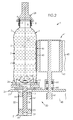
- the sidewall 6 may, as depicted in FIG.2 , include annular stiffening ribs 7 capable of resisting thermal and mechanical stresses undergone by the container 2 during filling, capping and subsequent handling.
- the container 2 has a base 8, which closes the container 2 and allows it to be normally put on a planar surface such as a table when used by a final customer.
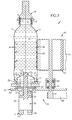
- the container base 8 includes a standing ring 9, which may be a high standing ring as it will be explained later, and a central invertible diaphragm 10, which has a symmetry around the main axis X and is deformable with respect to the sidewall 6 between an outwardly-inclined (or lower) position shown on FIG.2 , wherein the diaphragm 10 projects outwardly with respect to the container 2, and an inwardly-inclined (or upper) position, shown on FIG.3 , wherein the diaphragm 10 projects inwardly with respect to the container 2.
- a standing ring 9 which may be a high standing ring as it will be explained later
- a central invertible diaphragm 10 which has a symmetry around the main axis X and is deformable with respect to the sidewall 6 between an outwardly-inclined (or lower) position shown on FIG.2 , wherein the diaphragm 10 projects outwardly with respect to the container 2, and an inward
- the container 2 is blow molded with the diaphragm 10 in its lower position.
- the diaphragm 10 is capable of being mechanically forced upwards (i.e. inwards with respect to the container 2) after the container 2 has been filled with a pourable product, capped and cooled down, in order to compensate for the vacuum generated by the cooling of the product and to increase the overall rigidity of the filled container 2, for the benefits of container handling and customer quality perception.
- the standing ring 9 connects to the sidewall 6 of the container at a lower end portion 11 thereof.
- the standing ring 9 has a support flange 12 adjacent and substantially perpendicular to the lower end portion 11 of the sidewall 6, and a cylindrical or frustoconical inner portion 13, which connects the support flange 12 to the diaphragm 10.
- the support flange 12 is also substantially perpendicular to the container main axis X.
- the lower end portion 11 of the sidewall 6 has, when viewed in transversal section as shown on FIG.3 , the shape of an arch with a concavity turned inward with respect to the container 2, whereby the outer diameter of the support flange 12 is smaller than the overall diameter of the sidewall 6.
- the inner portion 13 preferably has the shape of a frustum of a cone and, when viewed in transversal section as shown on FIG.2 , inclines inwardly with respect to the container base 8, with a draft angle.
- the cone shape of the inner portion 13 provides a vault stiffening and locking function to the diaphragm 10 in its inverted position (shown in FIG.3 ), whereby the restriction of diameter of the inner portion 13 at its junction with the diaphragm 10 prevents the latter to articulate back from its inverted position with respect to the inner portion 13. As a result, re-inversion of the diaphragm 10 back to its initial outwardly-inclined position under the mere hydrostatic pressure of the poured product is prevented.
- the inner portion 13 has an axial extension, which is important with respect to the outer diameter of the support flange 12, hence the expression "high standing ring” to name the standing ring 9. More specifically, the axial extension (or height) of the inner portion 13 is greater than 1/10 of the outer diameter of the support flange 12, and preferably comprised between 1/10 and 1/5 of the outer diameter of the support flange 12.
- the invertible diaphragm 10 extends outwards in a frusto-conical shape from an outer edge 14 where the diaphragm 10 connects to an upper end of the inner portion 13, to an inner edge 15 where the diaphragm 10 connects to a central upwardly protruding recess 16.
- the axial extension, or height, of the diaphragm 10 is such that the inner edge 15 of the diaphragm 10 extends slightly above support plane defined at the junction between the support flange 12 and the lower end portion 11 of the sidewall 6.
- the height of the diaphragm 10 is slightly lower than the height of the standing ring 9.
- a filling step of pouring a product 17 such as a liquid, e.g. a beverage
- the container 2 is normally not fully filled, so that an empty volume (also called headspace) 18, remains above the product 17 within the neck 3.
- the volume of poured product 17 may vary from one container 2 to another.
- the headspace 18 may also vary from one container 2 to another, although the headspace 18 should always be substantially equal in volume to a reference headspace corresponding to the correct volume of dispensed product.
- the filled container 2 then undergoes a capping step of sealingly closing the mouth 4 (and hence the container 2) by means of a cap 19 mounted onto the neck 3.
- neck 3 and cap 19 are both correspondingly threaded and the cap 19 is screwed onto the neck 3 to provide sealing closure of the container 2.
- the container 2 may, in case the product 17 is poured hot, undergo a cooling step during which the container 2 and its content (product 17) are placed in a cooling tunnel, wherein they are artificially cooled down in a range from about 20°C to 35°C.
- the container 2 After having been capped, and, in the event the container 2 is cooled, after it has been cooled, the container 2 undergoes an inversion phase and a labeling phase.
- both phases may, as illustrated, be conducted within a same unit.
- the container handling machine 1 includes a plurality of processing units 20 each capable of conducting the labeling of the container 2 and the inversion of its diaphragm 10 to the inwardly-inclined position.
- Processing units 20 may, as depicted, be mounted onto a carrousel 21 including a frame 22 rotatably mounted around an axis 23 so as to be displaced around a circular path.
- the container handling machine 1 also comprises a rotary transfer unit 24, e.g. under the form of a star wheel provided with a plurality of peripheral gripping devices 25, which grab the filled and cap containers 2 from the capping unit and release each of them at a processing unit 20.
- a rotary transfer unit 24 e.g. under the form of a star wheel provided with a plurality of peripheral gripping devices 25, which grab the filled and cap containers 2 from the capping unit and release each of them at a processing unit 20.
- processing units 20 are identical, only one will be disclosed in detail hereinafter for the sake of clarity and simplicity.
- Each processing unit 20 comprises a hollow container support ring 26 suitable for engaging a container base 8. More precisely, the support ring 26 forms a counter print of at least the support flange 12 and the lower end portion 11 of the container sidewall 6.
- the container support ring 26 is rotatably mounted onto the frame 22, e.g. by means of a bearing 27.
- the processing unit 20 further includes a container retaining member 28 (only few of which are depicted on FIG.1 ) for rigidly retaining the container 2 in vertical position with its base located within the support ring 26 while the container 2 is being labeled and while the diaphragm 10 is being inverted.
- a container retaining member 28 (only few of which are depicted on FIG.1 ) for rigidly retaining the container 2 in vertical position with its base located within the support ring 26 while the container 2 is being labeled and while the diaphragm 10 is being inverted.
- the retaining member 28 is provided with a conical head suitable for vertically coming into abutment with the cap 19 along the container axis X.
- the processing unit 20 further includes a pusher 29 movable with respect to the frame 22 (and hence to the support ring 26) and capable of coming into abutment with the container base 8 through both the frame 22 and support ring 26 for inverting the diaphragm 10 from its outwardly-inclined position to its inwardly-inclined position.
- the pusher 29 is slidingly displaceable along axis X for coming into abutment within the central recess 16, as shown on FIG.3 .
- the pusher 29 has a tip 30, which is complementary in shape to the central recess 16, but the tip 30 may be of a simpler shape, such as a cylinder.
- the processing unit 20 further includes an actuator 31 for slidingly moving the pusher 29 frontwards (i.e. upwards) towards the container base 8 through the frame 22 in order to achieve inversion of the diaphragm 10, and backwards (i.e. downwards) thereafter, to be ready for another inversion cycle.
- the actuator 31 is a hydraulic or pneumatic cylinder, preferably of the two-way type.
- the actuator 31 has a cylinder housing 32, a piston 33 and a rod 34 fixed to the piston 33, with the pusher 29 mounted onto the rod 34 or integral therewith.
- the actuator 31 has a closure head 35 and a closure bottom 36 connected through the housing 32.
- the piston 33 defines within the housing 32 a front chamber 37 around the rod 34 and a back chamber 38 opposite to the rod 34, whereby the front chamber 37 is mainly defined between the piston 33 and the closure head 35 whereas the back chamber 38 is mainly defined between the piston 33 and the closure bottom 36.
- the back chamber 38 is in fluidic connection, through a bottom fluid port 39 formed in the closure bottom 36, with a control valve linked to a source of fluid (such as air or oil) under pressure and to a vent.
- the front chamber 37 is also in fluidic connection, through an upper fluid port 40 formed in the closure head 35, with a control valve linked to a source of fluid under pressure and to a vent.
- the back chamber 38 and front chamber 37 are alternately fluidly connected to the source of fluid and to the vent, so as to move the pusher 29 forth (or up) and back (or down) between a lower position in which the piston 33 is in the vicinity of the closure bottom 36 ( FIG.2 ), and an upper position in which the piston 33 is in the vicinity of the closure head 35 ( FIG.3 ).
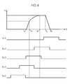
- Position (or height, denoted H) of the pusher 29 vs. time, within a container packaging cycle, is plotted on the uppermost curve of FIG.4 .
- the pusher 29 is initially in its lower position.
- the back chamber 38 is connected to the source of fluid and the front chamber 37 to the vent, so that the piston 33, together with the whole pusher 29, begins to move forward (or up), away from its lower position.
- the pusher 29 moves forward in a linear manner with respect to time as long as it encounters no resistance.
- the pusher 29 comes in contact with the container base, and more precisely with the central recess 16.
- the container base 8 resists to the upward movement of the piston 33, which is no longer linear in time but asymptotic as the pusher 29 reaches its upper position at instant t 2 (which, in practice, is of few tenths of a second after t 1 ) whereas the diaphragm 10 is inverted to its inwardly-inclined position ( FIG.3 ).
- the product 17, which is virtually incompressible, is displaced upwardly, whereby the gas (generally air) enclosed in the headspace 18 is compressed by a volume substantially equal to the volume (so-called extraction volume) swept by the diaphragm 10 during its inversion, between its outwardly-inclined and outwardly-inclined positions.
- inversion of the diaphragm 10 is achieved. From instant t 2 and until instant t 3 (which is from few seconds to several tens of seconds), the pusher 29 is held in its upper position to ensure stabilization (and dampen vibrations) of the diaphragm 10 in its inwardly-inclined position and prevent its re-inversion back to its outwardly-inclined position.
- the pusher may be electrically actuated by means of an electric motor, such as a linear motor.
- each processing unit 20 comprises a labeling device 41, which, in the depicted example, includes a driving pulley 42 and a driven pulley 43 both rotatably mounted onto the frame 22 (e.g. by means of bearings 44) and connected to each other through an endless labeling belt 45 carrying a label 46 to be affixed onto the container sidewall 6.
- a labeling device 41 which, in the depicted example, includes a driving pulley 42 and a driven pulley 43 both rotatably mounted onto the frame 22 (e.g. by means of bearings 44) and connected to each other through an endless labeling belt 45 carrying a label 46 to be affixed onto the container sidewall 6.
- the driving pulley 42 may be coupled, through a pinion 47 fixed to the pulley 42 and a driving belt 48, to a motor, which controls rotation and stopping of the driving pulley 42.
- One of the pulleys 42, 43 (the driving pulley 42 in the example depicted on FIG.2 and FIG.3 ) is located in the vicinity of the support ring 26, at a distance such that, when a container 2 is mounted on the support ring 26, the labeling belt 45 is in contact with the container sidewall 6 so as to be capable of wrapping a label 46 therearound as the container 2 is driven in rotation around its axis X by the retaining member 28 and/or by the support ring 26.
- the processing unit 20 also includes a glue applicator (not depicted) capable of applying a strip of glue either on an edge of the label 46 or directly on the container sidewall 6 to make the label 46 stick thereto.
- a glue applicator capable of applying a strip of glue either on an edge of the label 46 or directly on the container sidewall 6 to make the label 46 stick thereto.
- Initiation of the labeling phase of the container 2 is based on the timeline of the inversion step (or phase). More specifically, the labeling phase is initiated not later than 10 seconds after completion of the inversion step, i.e. not later than 10 seconds after t 2 .
- the labeling phase is initiated after completion of the inversion step, i.e. after instant t 2 .
- the advantage of such embodiment is that the container 2 is rigid, due to inversion of the diaphragm 10, which increases pressure inside the container 2.
- the labeling phase is initiated during inversion of the diaphragm 10, i.e. between instants t 1 and t 2 , and ends after completion of the inversion step, i.e. after t 2 .
- the labeling phase is initiated before initiation of the inversion step, i.e. before t 1 , and achieves after completion of the inversion step, i.e. after t 2 .
- the labeling phase is initiated before initiation of the inversion step, i.e. before t1, and achieves before completion the inversion phase, i.e. between t 1 and t 2 .
- the labeling phase is both initiated and completed before initiation of the inversion step, i.e. before t 1 .
- the label is firmly affixed to the container, and the use of thinner labels is possible.
Landscapes
- Labeling Devices (AREA)
Priority Applications (2)
| Application Number | Priority Date | Filing Date | Title |
|---|---|---|---|
| EP15305660.1A EP3088351A1 (de) | 2015-04-29 | 2015-04-29 | Verpackungsverfahren mit umkehr- und etikettierschritten auf einem behälter |
| PCT/EP2016/058437 WO2016173866A1 (en) | 2015-04-29 | 2016-04-15 | Packaging method including inversion and labeling steps on a container |
Applications Claiming Priority (1)
| Application Number | Priority Date | Filing Date | Title |
|---|---|---|---|
| EP15305660.1A EP3088351A1 (de) | 2015-04-29 | 2015-04-29 | Verpackungsverfahren mit umkehr- und etikettierschritten auf einem behälter |
Publications (1)
| Publication Number | Publication Date |
|---|---|
| EP3088351A1 true EP3088351A1 (de) | 2016-11-02 |
Family
ID=53177303
Family Applications (1)
| Application Number | Title | Priority Date | Filing Date |
|---|---|---|---|
| EP15305660.1A Withdrawn EP3088351A1 (de) | 2015-04-29 | 2015-04-29 | Verpackungsverfahren mit umkehr- und etikettierschritten auf einem behälter |
Country Status (2)
| Country | Link |
|---|---|
| EP (1) | EP3088351A1 (de) |
| WO (1) | WO2016173866A1 (de) |
Families Citing this family (2)
| Publication number | Priority date | Publication date | Assignee | Title |
|---|---|---|---|---|
| MX2021008543A (es) | 2019-01-15 | 2021-08-19 | Amcor Rigid Packaging Usa Llc | Base de contenedor de desplazamiento vertical. |
| CN115402551B (zh) * | 2022-06-20 | 2023-07-25 | 常州威斯敦粘合材料有限责任公司 | 用于pur热熔胶灌装的抽气组件和灌装机构、灌装方法 |
Citations (3)
| Publication number | Priority date | Publication date | Assignee | Title |
|---|---|---|---|---|
| DE102008026244A1 (de) * | 2008-05-30 | 2009-12-03 | Krones Ag | Verfahren zum Befüllen von Kunststoffflaschen und Flaschenfüller für Kunststoffflaschen |
| US8671653B2 (en) | 2003-07-30 | 2014-03-18 | Graham Packaging Company, L.P. | Container handling system |
| EP2851333A1 (de) * | 2013-09-19 | 2015-03-25 | Sidel S.p.a. Con Socio Unico | Behälterbehandlungsmaschine und Verfahren |
-
2015
- 2015-04-29 EP EP15305660.1A patent/EP3088351A1/de not_active Withdrawn
-
2016
- 2016-04-15 WO PCT/EP2016/058437 patent/WO2016173866A1/en not_active Ceased
Patent Citations (3)
| Publication number | Priority date | Publication date | Assignee | Title |
|---|---|---|---|---|
| US8671653B2 (en) | 2003-07-30 | 2014-03-18 | Graham Packaging Company, L.P. | Container handling system |
| DE102008026244A1 (de) * | 2008-05-30 | 2009-12-03 | Krones Ag | Verfahren zum Befüllen von Kunststoffflaschen und Flaschenfüller für Kunststoffflaschen |
| EP2851333A1 (de) * | 2013-09-19 | 2015-03-25 | Sidel S.p.a. Con Socio Unico | Behälterbehandlungsmaschine und Verfahren |
Also Published As
| Publication number | Publication date |
|---|---|
| WO2016173866A1 (en) | 2016-11-03 |
Similar Documents
| Publication | Publication Date | Title |
|---|---|---|
| JP6321677B2 (ja) | 容器充填機および容器充填方法 | |
| US10259696B2 (en) | Machine and method for processing filled containers having an invertible diaphragm | |
| US10017370B2 (en) | Machine and method for filling containers | |
| US7926243B2 (en) | Method and system for handling containers | |
| US8596029B2 (en) | System and method for pressurizing a plastic container | |
| US9156669B2 (en) | Liquid bottling method and machine, in particular for carbonated liquids or oxygen sensitive liquids | |
| AU2003211399B2 (en) | Method and plant for applying a heat-shrinkable label to containers | |
| CA2779016A1 (en) | Pressurized capping apparatus | |
| CA2707701C (en) | Container handling system | |
| JP7139115B2 (ja) | 湾曲した反転可能なダイヤフラムを備え付ける容器 | |
| CN103796945A (zh) | 用于测定灌装生产线上容器的完整性和密封性的方法 | |
| US20220388826A1 (en) | Automatic Container Closing Machine | |
| US3946540A (en) | Heat seal capper head assembly | |
| WO2016173866A1 (en) | Packaging method including inversion and labeling steps on a container | |
| AU689619B2 (en) | A beverage packaging apparatus and a beverage packaging method | |
| EP3106402A1 (de) | Prozess und vorrichtung zum verschliessen und bedrucken/etikettieren eines behälters | |
| EP4074649B1 (de) | Verschlussvorrichtung und verschlussverfahren | |
| EP3009393A1 (de) | Verfahren zur Bearbeitung gefüllter Behälter mit einer invertierbaren Membran | |
| EP3081527B1 (de) | Verfahren zur herstellung einer behälterverpackung mit umgebungsfüllung und umkehrmembran | |
| CN105217547A (zh) | 压盖机 | |
| US1363824A (en) | Means for capping or closing bottles and other containers | |
| US6619016B1 (en) | Method for filling and capping containers such as screw top bottles and the screw top closures therefor | |
| US20130199130A1 (en) | System and method for pressurizing a plastic container | |
| CN108946631B (zh) | 一种农产品包装设备 | |
| WO2013177150A1 (en) | System and method for pressurizing a plastic container |
Legal Events
| Date | Code | Title | Description |
|---|---|---|---|
| PUAI | Public reference made under article 153(3) epc to a published international application that has entered the european phase |
Free format text: ORIGINAL CODE: 0009012 |
|
| AK | Designated contracting states |
Kind code of ref document: A1 Designated state(s): AL AT BE BG CH CY CZ DE DK EE ES FI FR GB GR HR HU IE IS IT LI LT LU LV MC MK MT NL NO PL PT RO RS SE SI SK SM TR |
|
| AX | Request for extension of the european patent |
Extension state: BA ME |
|
| 17P | Request for examination filed |
Effective date: 20170104 |
|
| RBV | Designated contracting states (corrected) |
Designated state(s): AL AT BE BG CH CY CZ DE DK EE ES FI FR GB GR HR HU IE IS IT LI LT LU LV MC MK MT NL NO PL PT RO RS SE SI SK SM TR |
|
| STAA | Information on the status of an ep patent application or granted ep patent |
Free format text: STATUS: THE APPLICATION HAS BEEN WITHDRAWN |
|
| 18W | Application withdrawn |
Effective date: 20170516 |