EP3088610B1 - Protection contre l'érosion pour un fond sous-marin le long de la paroi d'un quai, et son procédé de fabrication - Google Patents
Protection contre l'érosion pour un fond sous-marin le long de la paroi d'un quai, et son procédé de fabrication Download PDFInfo
- Publication number
- EP3088610B1 EP3088610B1 EP15165792.1A EP15165792A EP3088610B1 EP 3088610 B1 EP3088610 B1 EP 3088610B1 EP 15165792 A EP15165792 A EP 15165792A EP 3088610 B1 EP3088610 B1 EP 3088610B1
- Authority
- EP
- European Patent Office
- Prior art keywords
- slabs
- scour protection
- foundation
- rocks
- protection according
- Prior art date
- Legal status (The legal status is an assumption and is not a legal conclusion. Google has not performed a legal analysis and makes no representation as to the accuracy of the status listed.)
- Active
Links
Images


Classifications
-
- E—FIXED CONSTRUCTIONS
- E02—HYDRAULIC ENGINEERING; FOUNDATIONS; SOIL SHIFTING
- E02B—HYDRAULIC ENGINEERING
- E02B3/00—Engineering works in connection with control or use of streams, rivers, coasts, or other marine sites; Sealings or joints for engineering works in general
- E02B3/04—Structures or apparatus for, or methods of, protecting banks, coasts, or harbours
- E02B3/06—Moles; Piers; Quays; Quay walls; Groynes; Breakwaters ; Wave dissipating walls; Quay equipment
-
- E—FIXED CONSTRUCTIONS
- E02—HYDRAULIC ENGINEERING; FOUNDATIONS; SOIL SHIFTING
- E02B—HYDRAULIC ENGINEERING
- E02B3/00—Engineering works in connection with control or use of streams, rivers, coasts, or other marine sites; Sealings or joints for engineering works in general
- E02B3/04—Structures or apparatus for, or methods of, protecting banks, coasts, or harbours
- E02B3/12—Revetment of banks, dams, watercourses, or the like, e.g. the sea-floor
- E02B3/14—Preformed blocks or slabs for forming essentially continuous surfaces; Arrangements thereof
-
- E—FIXED CONSTRUCTIONS
- E02—HYDRAULIC ENGINEERING; FOUNDATIONS; SOIL SHIFTING
- E02B—HYDRAULIC ENGINEERING
- E02B3/00—Engineering works in connection with control or use of streams, rivers, coasts, or other marine sites; Sealings or joints for engineering works in general
- E02B3/04—Structures or apparatus for, or methods of, protecting banks, coasts, or harbours
- E02B3/06—Moles; Piers; Quays; Quay walls; Groynes; Breakwaters ; Wave dissipating walls; Quay equipment
- E02B3/066—Quays
-
- E—FIXED CONSTRUCTIONS
- E02—HYDRAULIC ENGINEERING; FOUNDATIONS; SOIL SHIFTING
- E02B—HYDRAULIC ENGINEERING
- E02B3/00—Engineering works in connection with control or use of streams, rivers, coasts, or other marine sites; Sealings or joints for engineering works in general
- E02B3/04—Structures or apparatus for, or methods of, protecting banks, coasts, or harbours
- E02B3/12—Revetment of banks, dams, watercourses, or the like, e.g. the sea-floor
- E02B3/122—Flexible prefabricated covering elements, e.g. mats, strips
- E02B3/123—Flexible prefabricated covering elements, e.g. mats, strips mainly consisting of stone, concrete or similar stony material
-
- E—FIXED CONSTRUCTIONS
- E02—HYDRAULIC ENGINEERING; FOUNDATIONS; SOIL SHIFTING
- E02B—HYDRAULIC ENGINEERING
- E02B17/00—Artificial islands mounted on piles or like supports, e.g. platforms on raisable legs or offshore constructions; Construction methods therefor
- E02B17/0017—Means for protecting offshore constructions
Definitions
- the present invention relates to a scour protection for an underwater bottom extending alongside a quay wall.
- the invention further relates to a method for providing such scour protection.
- Marine transport is ever increasing, both in quantity and size.
- the last decade has seen developments in the shipping industry characterized by an increase in capacity.
- Vessels are becoming larger and larger in order to be able to carry as much load as possible.
- the increasing size of freight carriers and cruise ships has an important impact on harbor infrastructure, as docking basins need to be made deeper and quay walls stronger.
- the larger vessels presently being developed are equipped with far more power than known hitherto.
- the flow velocities against the quay walls and the harbor underwater bottom in front of the quay wall that are associated with the larger and more powerful propellers used on these vessels are anticipated to increase at such level that important damage may be caused to the quay walls and harbor underwater bottoms in particular. This damaging effect becomes more of a problem since modern vessels tend to have secondary propulsion systems such as bow and stern thrusters in order to increase their maneuverability, in particular while berthing.
- Scour protection of underwater bottoms in harbors is known.
- Existing scour protection at the toe of a quay wall may comprise a granular protection, to which may be added liquid asphalt mastic for additional strength.
- Other known scour protection comprises mattresses of concrete blocks, rock or fibrous stone asphalt. These mattresses are easily applied to an underwater bottom, and for most applications provide sufficient strength, among other factors due to the flexible nature of a mattress. These materials however may not always provide adequate protection, or may not be available at the site.
- FR-A-2 125 826 discloses a scour protection according to the preamble of claim 1 and a method for providing a scour protection according to the preamble of claim 16.
- the above aim is provided by a scour protection for an underwater bottom alongside a quay wall in accordance with claim 1.
- the scour protection of the invention comprises a foundation/leveling layer of rocks with a size distribution conforming to 100 ⁇ D n50 ⁇ 225 mm, and a plurality of prefabricated reinforced concrete slabs, adjacently positioned on top of the foundation/levelling layer and leaving a gap between edges of the slabs. It has turned out that a foundation/leveling layer in accordance with the invention provides a reliable and adequate support for the concrete slabs, and that the gap between edges of the slabs is instrumental in the long term protection offered by the invention.
- the known classically used scour protection in the form of mattresses or granular protection requires large and heavy rocks up to 1-5 tons to withstand the typical thrust forces generated by a vessel. These rocks may not be readily available and further need to be applied in rather thick layers. This reduces the maximum available water depth alongside the quay wall.
- the scour protection of the present invention does not have this drawback.
- Known granular protection may also need accurate installation and leveling.
- the scour protection thickness and density thus obtained is rather arbitrary and depends to some extent on the experience of the crane driver. Quality control tests performed upon completion of the works by the client or the contractor, in particular measurements of minimal thickness and density may result in a wide and undesirable variation.
- the scour protection of the present invention does not have this problem and provides an accurate thickness and density to the scour protection. This allows to accurately defining the depth of the underwater bottom.
- the foundation/leveling layer comprises rock with the claimed size distribution, whereby the wording rock may encompass any granular material such as rocks and/or stones, either natural and/or man-made.
- the gap width between edges of the slabs may be chosen according to the selected size distribution of the rocks of the foundation/leveling layer.
- a particularly preferred embodiment of the invention provides a scour protection wherein the gap width ranges from 10-100 mm, more preferably from 20-90 mm, and most preferably from 30-60 mm. The preferred embodiments help preventing washing out of underwater bottom layers below the slabs, and add to the stability of the scour protection.
- the gaps between the concrete slabs should be present along one edge of each of at least two slabs, preferably along two edges of each of at least three slabs, more preferably along three edges of each of at least four slabs, and most preferably along four edges of each of at least five slabs.
- the gaps may be present along edges that extend substantially parallel to an alongside direction of the quay wall, and/or may be present along edges that extend substantially perpendicular to the alongside direction of the quay wall.
- the gap width between slabs is preferably a constant but may vary along an edge of two adjacently positioned slabs, preferably within 50% of the average gap width, more preferably within 20% of the average gap width, and most preferably within 10% of the average gap width.
- the scour protection according to the invention advantageously allows maximizing the available water depth alongside the quay wall. It has turned out that the average thickness of the foundation/levelling layer and of in particular of the concrete slabs may be selected much smaller than with the known granular scour protection for instance.
- a scour protection is provided wherein the slabs have a thickness ranging from 200-500 mm, more preferably from 275-425 mm, and most preferably from 325-375 mm. These preferred thicknesses provide the required protection against erosion, and further allow handling the slabs while positioning them on an underwater bottom.
- An important advantage of the invented scour protection relates to an embodiment wherein concrete slabs are provided onto the foundation/leveling layer without requiring mutual connection of slabs. This facilitates replacement of a damaged slab by another slab.
- the scour protection in accordance with the invention requires a gap between edges of the concrete slabs.
- an embodiment relates to a scour protection wherein edges of the slabs are provided with distance holders or spacing lugs.
- the spacing lugs may be separate or may be integral to the slab, and can be made from concrete, wood, rubber or another polymer, metal, and other suitable materials.
- the spacing lugs or distance holders are instrumental in maintaining the required gap between slab edges.
- the invented scour protection comprises a foundation/leveling layer of rocks with a size distribution conforming to 100 ⁇ D n50 ⁇ 225 mm.
- D n50 is meant the nominal rock size that is exceeded by 50 wt.-% of the rocks.
- Other useful embodiments of the invention provide a scour protection wherein the size distribution of the rocks conforms to 100 ⁇ D n50 ⁇ 185 mm, more preferably to 100 ⁇ D n50 ⁇ 155 mm, and most preferably to 110 ⁇ D n50 ⁇ 130 mm.
- a scour protection is provided wherein the size distribution of the rocks is selected such that at most 10 wt.-% of the rocks has a size ⁇ 100 mm, and/or at most 10 wt.-% of the rocks has a size > 225 mm. In a particularly useful embodiment, at least 80 wt.-% of the rocks has a size between 100-225 mm.
- the foundation/leveling layer serves to support the concrete slabs, and distributes the forces to the underlying soils.
- a scour protection is provided wherein the foundation/levelling layer is level to within 200 mm, and more preferably to within 100 mm.
- the foundation/leveling layer may be horizontal but may also have a slope exhibiting an angle with the horizontal direction, whereby the angle may be between 0-40 degrees, more preferably between 0-30 degrees, and most preferably between 0-20 degrees.
- the scour protection according to the invention may be provided at any depth under water.
- a scour protection is provided wherein at least some of the slabs are provided at a depth of at least 15 m, more preferably at least 20 m, and most preferably at least 25 m.
- the concrete slabs of the scour protection may have any shape and may be curved or flat.
- An embodiment of the invention relates to a scour protection wherein the slabs are planar, and the edges of the slabs are straight and extend in a thickness direction perpendicular to the plane of the slabs.
- a practical embodiment of the invention provides a scour protection wherein the slabs have a lateral dimension of at least 3.5 m, more preferably at least 6 m, and most preferably at least 7 m.
- a preferred scour protection comprises at least some slabs having a size of 8 x 8 x 0.35 m, with a variation of at most 40% of each dimension, more preferably at most 30% of each dimension, and most preferably at most 20% of each dimension.
- the scour protection may extend in a transverse distance perpendicular to the quay wall over 1-10 meters only, over at least 10 meters, or over more than 100 m.
- the scour protection may extend in a longitudinal direction parallel to (alongside) the quay wall over a few meters only, preferably over more than 100 m, and more preferably over more than 1 km.
- the invention further provides an embodiment of a scour protection wherein the slabs are provided with a number of holes that extend from a front surface of the slabs to a back surface thereof.
- the holes interact with the gaps between the slabs in preventing uplifting forces that may destabilize the slabs.
- the holes are further instrumental in facilitating the placement of the slabs onto an underwater bottom.
- the number of holes in the slabs may be chosen within a large range.
- the number of holes in one slab ranges from 10-100, more preferably from 20-90, and most preferably from 30-80.
- a preferred hole density ranges from 0,5 to 5 holes per m 2 , more preferably from 0,8 to 3 holes per m 2 , and most preferably from 0,9 to 2 holes per m 2 .
- a cross-dimension of the holes (for instance the diameter in case of cylindrical holes) may be chosen within large ranges but is preferably selected between 20-200 mm, more preferably between 40-150 mm, and most preferably between 50-100 mm.
- an embodiment of the scour protection according to the invention is characterized in that the slabs comprise lifting brackets.
- the lifting brackets may be integrated into the concrete slabs during casting thereof, and may for instance comprise steel brackets.
- the concrete slabs of the invented scour protection are prefabricated, preferably at or close to the site where the scour protection has to be provided.
- the slabs comprise reinforcement in the form of a number of reinforcement bars (rebars), the number and properties of which are determined according to well known calculation principles.
- the rebars are instrumental in providing the slabs with the necessary strength when placed under water but also during lifting and positioning of the slabs onto the foundation/leveling layer.
- An improvement of the scour protection is obtained in an embodiment that further comprises a geotextile layer, preferably provided below the foundation/leveling layer.
- the underwater bottom may first be provided with a ground filter layer that may partly extend underneath the quay wall.
- the underwater bottom is in the present embodiment covered with a geotextile layer.
- the geotextile layers are typically placed parallel to each other and with a certain overlap, and the foundation/levelling layer is preferably provided thereon.
- the invention also relates to a method for providing a scour protection for an underwater bottom alongside a quay wall in accordance with claim 16.
- the invented method comprises providing a foundation/leveling layer of rocks with a size distribution conforming to 100 ⁇ D n50 ⁇ 225 mm on the bottom, and adjacently positioning a plurality of prefabricated reinforced concrete slabs on top of the foundation/levelling layer such that a gap is left between edges of the slabs.
- the scour protection is particularly advantageous for placement under water at considerable depths of at least 15 m, more preferably at least 20 m, and most preferably at least 25 m.
- the foundation/leveling layer may conveniently be provided onto an existing underwater bottom by dumping the rocks into the water from a vessel, preferably a vessel with a fall pipe, from a crane, or from any other suitable tool or device.
- the lifting of the slabs and subsequent positioning of the slabs onto the foundation/leveling layer may conveniently be carried out by a lifting device that is preferably provided with a lifting frame from which a slab may conveniently be suspended.
- the lifting frame and/or the slab itself may be provided with positioning and/or measuring tools, such as sonars, and the like.
- Preferred embodiments of the invention relate to a method wherein the slabs are positioned such that the gap between edges of the slabs ranges from 20-100 mm, and more preferably from 30-90 mm; wherein the slabs have a thickness ranging from 200-500 mm, more preferably from 275-425 mm, and most preferably from 325-375 mm; wherein edges of the slabs are provided with distance holders or spacing lugs; wherein the size distribution of the rocks conforms to 110 ⁇ D n50 ⁇ 130 mm; wherein the size distribution of the rocks is selected such that at most 10 wt.-% is ⁇ 100 mm, and/or at most 10 wt.-% is > 225 mm; wherein the foundation/levelling layer is level to within 200 mm; wherein at least some of the slabs are provided at a depth of at least 15 m, more preferably at least 20 m, and most preferably at least 25 m; wherein the slabs are planar, and the edges of the slabs are straight
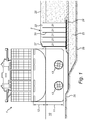
- the vessel 1 may be any vessel of considerable size, and comprises a Malaccamax container ship for illustrative purposes.
- a Malaccamax ship has the maximum dimensions that are still permissible to pass the most restrictive area of the Malacca Strait.
- a Malaccamax container ship typically has a draught of about 21 m, which is comparable to VLCC (Very Large Crude Carriers) vessels for instance.
- a Malaccamax container ship typically would have the following characteristics fully loaded:
- the vessel 1 has a draught 11 of about 21 m, and extends above the water 10 over a distance 12 of about 14 m.
- the water level is at 0.3 m CD (chart datum).
- the toe of the quay wall 2 is at -23,5 CD, while the maximum depth of the water basin alongside the quay wall 2 is at -26.5 m CD.
- the vessel 1 is at its stern equipped with two main propellers 13. Stern thrusters are not shown.
- the quay wall itself comprises for illustrative purpose a number of caissons 20, filled with dredged material 21.
- the caissons 20 are provided with a steel top plate 22, and extend over several km in an alongside direction of the quay wall 2.
- the caissons 20 rest on a foundation layer of compacted sand key 23, provided with a top layer of rock mound 24.
- the sand key 23 is preferably compacted and has been provided in a dredged volume of bottom material 25.
- the caissons 20 are on top provided with a sand surcharge 26 that is retained by a retaining ridge member 27 that extends alongside the quay wall 1.
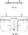
- the slabs 5 comprise a number of planar and square slabs 5a of 8 x 8 m wide and 0.35 m thick.
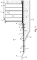
- the thickness 40 of the foundation/leveling layer 4 is about 0.5 m and gradually increases in thickness towards the quay wall 2 to a thickness 41 close to the quay wall toe of about 1.5 m.
- the slope 42 of the foundation/leveling layer 4 is about 11 degrees.
- the scour protection 3 shown in figure 2 further comprises a geotextile layer 6, provided between the foundation/leveling layer 4 and the bottom 25.
- the geotextile layer comprises a PP geotextile fabric and extends from the toe of the quay wall 2 to an opposite end of a deepened area 60 of the water basin 10.
- the scour protection 3 comprises a foundation/leveling layer 4 with a thickness 40 of about 0.5 m and a number of reinforced concrete slabs 5a having a thickness 50 of about 0.35 mm.
- the gap width 51 between slabs 5a ranges from 40-80 mm.
- the edges 58 of the slabs 5a are provided with spacing lugs 52 to provide the gap width 51.
- Reinforcing strips 53 are provided at the corners of each slab 5a.
- the slabs 5a are further provided with a number of holes 54 that extend from a front surface 55a of the slabs 5 to a back surface 55b thereof. About 64 holes are regularly distributed over the surfaces (55a, 55b).
- the slabs 5 also comprise lifting brackets 56, as shown in the side view of figure 3C .
- FIG 4 an embodiment of a method for providing an underwater bottom 25 alongside a quay wall 2 with scour protection 3 is shown.
- the method comprises providing a foundation/leveling layer 4 of rocks with a size distribution conforming to 100 ⁇ D n50 ⁇ 225 mm on the bottom 25, and adjacently positioning a plurality of prefabricated reinforced concrete slabs 5 on top of the foundation/levelling layer 4 such that a gap 51 is left between edges 58 of the slabs 5.
- the slabs 5 are conveniently placed on top of the foundation/leveling layer 4 by a suitable lifting device, such as a crane (not shown) operated from the shore or from a vessel or pontoon.
- a lifting frame 7 is suspended by wires 71 from a hook of the crane.
- suspending wires 72 which may be paid out or retracted by a suitable mechanism 73 provided on the frame 7.
- a slab 5 is attached to the wires 72 and brought under water by lowering a crane boom and/or paying out the wires (71, 72).
- the spacing lugs 52 allow to position the slabs 5 onto the foundation/leveling layer 4 such that a suitable gap width is maintained between edges 58 of adjacently positioned slabs 5.
- the frame 7 further may be provided with sonar or other positioning systems for accurate positioning of the slabs 5.
- the holes 54 in the slabs 5 allow to let the water escape from underneath the slab 5 while lowering it into the water, which further helps in accurate placement of the slabs 5.
Landscapes
- Engineering & Computer Science (AREA)
- General Engineering & Computer Science (AREA)
- Environmental & Geological Engineering (AREA)
- Ocean & Marine Engineering (AREA)
- Mechanical Engineering (AREA)
- Civil Engineering (AREA)
- Structural Engineering (AREA)
- Revetment (AREA)
- Devices Affording Protection Of Roads Or Walls For Sound Insulation (AREA)
Claims (16)
- Protection anti-affouillement (3) pour fond subaquatique le long du mur d'un quai, comprenant une couche de fondation/nivellement en roches (4) et une pluralité de dalles préfabriquées en béton armé (5, 5a, 5b, 5c), la couche de fondation/nivellement en roches assurant un support et un nivellement adéquats pour la pluralité de dalles préfabriquées en béton armé, étant entendu que les dalles ont été positionnées adjacentes par-dessus la couche de fondation/nivellement en roches, un espace (51) ayant été laissé entre les rives (58) des dalles, caractérisée en ce que la couche de fondation/nivellement en roches présente une distribution granulométrique conforme à 100 < Dn50 < 225 mm et en ce que les dalles ont une dimension latérale d'au moins 3,5 m.
- Protection anti-affouillement selon la revendication 1, étant entendu que la largeur de l'espace va de 10 à 100 mm, de préférence de 20 à 90 mm et, de manière particulièrement préférée, de 30 à 60 mm.
- Protection anti-affouillement selon la revendication 1 ou 2, étant entendu que les dalles ont une épaisseur allant de 200 à 500 mm, de préférence de 275 à 425 mm et, de manière particulièrement préférée, de 325 à 375 mm.
- Protection anti-affouillement selon l'une quelconque des revendications précédentes, étant entendu que les rives des dalles sont dotées d'entretoises ou de tenons d'écartement (52).
- Protection anti-affouillement selon l'une quelconque des revendications précédentes, étant entendu que la distribution granulométrique des roches est conforme à 110 < Dn50 < 130 mm.
- Protection anti-affouillement selon l'une quelconque des revendications précédentes, étant entendu que la distribution granulométrique des roches est sélectionnée de telle sorte qu'au plus 10 % en poids des roches aient une taille < 100 mm et/ou qu'au plus 10 % en poids des roches aient une taille > 225 mm.
- Protection anti-affouillement selon l'une quelconque des revendications précédentes, étant entendu que la couche de fondation/nivellement est horizontale à 200 mm près.
- Protection anti-affouillement selon l'une quelconque des revendications précédentes, étant entendu qu'au moins certaines des dalles sont aménagées à une profondeur d'au moins 15 m, de préférence d'au moins 20 m et, de manière particulièrement préférée, d'au moins 25 m.
- Protection anti-affouillement selon l'une quelconque des revendications précédentes, étant entendu que les dalles sont planes et que les rives des dalles sont rectilignes et s'étendent dans le sens de l'épaisseur perpendiculairement au plan des dalles.
- Protection anti-affouillement selon l'une quelconque des revendications précédentes, étant entendu que les dalles sont dotées d'un certain nombre de trous (54) qui s'étendent depuis une surface antérieure (55a) des dalles jusqu'à une surface postérieure (55b) de celles-ci.
- Protection anti-affouillement selon la revendication 10, étant entendu que le nombre de trous va de 10 à 100, de préférence de 20 à 90 et, de manière particulièrement préférée, de 30 à 80.
- Protection anti-affouillement selon l'une quelconque des revendications précédentes, étant entendu que les dalles ont une dimension latérale d'au moins 5 m, de préférence d'au moins 6 m et, de manière particulièrement préférée, d'au moins 7 m.
- Protection anti-affouillement selon l'une quelconque des revendications précédentes, étant entendu qu'au moins certaines dalles ont une taille de 8 x 8 x 0,35 m, chaque dimension présentant une variation d'au plus 20 %.
- Protection anti-affouillement selon l'une quelconque des revendications précédentes, étant entendu que les dalles comprennent des pattes de levage (56).
- Protection anti-affouillement selon l'une quelconque des revendications précédentes, comprenant par ailleurs une couche (6) de géotextile, de préférence aménagée sous la couche de fondation/nivellement.
- Procédé d'aménagement d'une protection anti-affouillement (3) pour fond subaquatique le long du mur d'un quai, le procédé consistant à aménager une couche de fondation/nivellement en roches (4) sur le fond et à positionner adjacentes une pluralité de dalles préfabriquées en béton armé (5, 5a, 5b, 5c) par-dessus la couche de fondation/nivellement de telle sorte qu'un espace (51) soit laissé entre les rives (58) des dalles, la couche de fondation/nivellement assurant la fonction combinée de support et de nivellement adéquats pour les dalles en béton, caractérisé en ce que la couche de fondation/nivellement en roches présente une distribution granulométrique conforme à 100 < Dn50 < 225 mm et en ce que les dalles ont une dimension latérale d'au moins 3,5 m.
Priority Applications (7)
| Application Number | Priority Date | Filing Date | Title |
|---|---|---|---|
| DK15165792.1T DK3088610T3 (en) | 2015-04-29 | 2015-04-29 | Erosion protection for an underwater floor along a quay wall and method for its preparation |
| EP15165792.1A EP3088610B1 (fr) | 2015-04-29 | 2015-04-29 | Protection contre l'érosion pour un fond sous-marin le long de la paroi d'un quai, et son procédé de fabrication |
| PCT/EP2016/059277 WO2016174029A1 (fr) | 2015-04-29 | 2016-04-26 | Protection contre l'affouillement pour un fond sous-marin le long d'une paroi de quai, et procédé pour la fournir |
| MYPI2017704050A MY189807A (en) | 2015-04-29 | 2016-04-26 | Scour protection for an underwater bottom alongside a quay wall, and method for providing the same |
| CN201680024257.8A CN107709669A (zh) | 2015-04-29 | 2016-04-26 | 沿码头岸壁的水下底部的冲刷防护结构及提供该防护结构的方法 |
| KR1020177033069A KR102616709B1 (ko) | 2015-04-29 | 2016-04-26 | 안벽의 옆을 따라 있는 수중 바닥을 위한 세굴 방지부 및 이러한 세굴 방지부를 제공하기 위한 방법 |
| PH12017501962A PH12017501962B1 (en) | 2015-04-29 | 2017-10-27 | Scour protection for an underwater bottom alongside a quay wall, and method for providing the same |
Applications Claiming Priority (1)
| Application Number | Priority Date | Filing Date | Title |
|---|---|---|---|
| EP15165792.1A EP3088610B1 (fr) | 2015-04-29 | 2015-04-29 | Protection contre l'érosion pour un fond sous-marin le long de la paroi d'un quai, et son procédé de fabrication |
Publications (2)
| Publication Number | Publication Date |
|---|---|
| EP3088610A1 EP3088610A1 (fr) | 2016-11-02 |
| EP3088610B1 true EP3088610B1 (fr) | 2018-11-14 |
Family
ID=53039305
Family Applications (1)
| Application Number | Title | Priority Date | Filing Date |
|---|---|---|---|
| EP15165792.1A Active EP3088610B1 (fr) | 2015-04-29 | 2015-04-29 | Protection contre l'érosion pour un fond sous-marin le long de la paroi d'un quai, et son procédé de fabrication |
Country Status (7)
| Country | Link |
|---|---|
| EP (1) | EP3088610B1 (fr) |
| KR (1) | KR102616709B1 (fr) |
| CN (1) | CN107709669A (fr) |
| DK (1) | DK3088610T3 (fr) |
| MY (1) | MY189807A (fr) |
| PH (1) | PH12017501962B1 (fr) |
| WO (1) | WO2016174029A1 (fr) |
Families Citing this family (4)
| Publication number | Priority date | Publication date | Assignee | Title |
|---|---|---|---|---|
| JP6309148B1 (ja) * | 2017-07-21 | 2018-04-11 | 有限会社キシムラ | 防砂シート敷設構造 |
| CN112049421A (zh) * | 2020-08-30 | 2020-12-08 | 广东省水利水电第三工程局有限公司 | 一种自密实堆石混凝土施工工艺 |
| CN113684856A (zh) * | 2021-08-31 | 2021-11-23 | 华能(浙江)能源开发有限公司清洁能源分公司 | 具有蜗杆导沙功能的海上风电基础 |
| CN119392711B (zh) * | 2025-01-03 | 2025-04-15 | 浙江世润建创科技发展有限公司 | 海上风机大直径钢管桩泵送固化土冲刷防护施工方法 |
Family Cites Families (17)
| Publication number | Priority date | Publication date | Assignee | Title |
|---|---|---|---|---|
| US1993217A (en) * | 1932-12-19 | 1935-03-05 | Union Oil Co | Revetment structure |
| FR1006559A (fr) * | 1948-02-02 | 1952-04-24 | Procédé de réalisation de quais en terrain vaseux et quais réalisés selon ce procédé | |
| FR1437602A (fr) * | 1965-03-22 | 1966-05-06 | Neyrpic Ets | Revêtement ou remplissage des bassins d'amortissement affouillés ou susceptibles de l'être |
| DE2107030A1 (de) * | 1971-02-15 | 1972-08-31 | E.A.H. Naue Kg, 4992 Espelkamp | Deckwerk für Dämme, Deiche und andere Wasserbauten |
| JP3758099B2 (ja) * | 1996-08-05 | 2006-03-22 | 株式会社大林組 | 水質浄化堤 |
| US5924820A (en) * | 1997-02-26 | 1999-07-20 | Creter; Richard E. | Anti-scour device and method for scour prevention |
| CN2365261Y (zh) * | 1998-09-03 | 2000-02-23 | 彭继源 | 镶嵌式混凝土防浪护坡板 |
| US6558074B2 (en) * | 2001-07-19 | 2003-05-06 | Jan Erik Jansson | Assembly of revetments with crush-absorbing ribs |
| US20040265060A1 (en) * | 2001-10-26 | 2004-12-30 | Lee Keun-Hee | Method for constructing scour protection of bridge and stabilization of stream bed using block mat |
| CN2737831Y (zh) * | 2004-01-09 | 2005-11-02 | 郑士元 | 一种组合板 |
| CN101761052A (zh) * | 2008-11-11 | 2010-06-30 | 李凤 | 混凝土护堤板 |
| KR100920400B1 (ko) * | 2009-03-17 | 2009-10-07 | 일광콘크리트공업 (주) | 수질정화용 식생호안블록 |
| CN101514547B (zh) * | 2009-03-23 | 2011-01-12 | 河南省燕山水库建设管理局 | 一种堤坝护坡 |
| CN101967811B (zh) * | 2009-07-27 | 2012-12-26 | 北京仁创科技集团有限公司 | 一种水利设施 |
| KR101162904B1 (ko) * | 2012-04-17 | 2012-07-05 | 국민대학교산학협력단 | 해저 연약지반의 세굴방지용 심층혼합처리공법 및 이를 이용하여 시공되는 기초구조체 |
| CN203411948U (zh) * | 2013-08-01 | 2014-01-29 | 鸿鑫建设集团有限公司 | 一种绿色生态河道护坡结构 |
| CN204059284U (zh) * | 2014-08-19 | 2014-12-31 | 东南大学 | 一种人工河道护岸及河底结构 |
-
2015
- 2015-04-29 EP EP15165792.1A patent/EP3088610B1/fr active Active
- 2015-04-29 DK DK15165792.1T patent/DK3088610T3/en active
-
2016
- 2016-04-26 CN CN201680024257.8A patent/CN107709669A/zh active Pending
- 2016-04-26 MY MYPI2017704050A patent/MY189807A/en unknown
- 2016-04-26 KR KR1020177033069A patent/KR102616709B1/ko active Active
- 2016-04-26 WO PCT/EP2016/059277 patent/WO2016174029A1/fr not_active Ceased
-
2017
- 2017-10-27 PH PH12017501962A patent/PH12017501962B1/en unknown
Non-Patent Citations (1)
| Title |
|---|
| None * |
Also Published As
| Publication number | Publication date |
|---|---|
| KR20170141724A (ko) | 2017-12-26 |
| EP3088610A1 (fr) | 2016-11-02 |
| CN107709669A (zh) | 2018-02-16 |
| PH12017501962A1 (en) | 2018-03-19 |
| PH12017501962B1 (en) | 2023-10-11 |
| MY189807A (en) | 2022-03-09 |
| KR102616709B1 (ko) | 2023-12-20 |
| WO2016174029A1 (fr) | 2016-11-03 |
| DK3088610T3 (en) | 2019-03-11 |
Similar Documents
| Publication | Publication Date | Title |
|---|---|---|
| DK3088610T3 (en) | Erosion protection for an underwater floor along a quay wall and method for its preparation | |
| KR101095496B1 (ko) | 노후 잔교식 안벽의 개축 공법 및 중력식 구조의 널말뚝 안벽 | |
| US5853264A (en) | Bridge, dock and pier shoring-up bulk-delivery floating conveyor unit | |
| HK1230681B (en) | Scour protection for an underwater bottom alongside a quay wall, and method for providing the same | |
| HK1230681A (en) | Scour protection for an underwater bottom alongside a quay wall, and method for providing the same | |
| HK1230681A1 (en) | Scour protection for an underwater bottom alongside a quay wall, and method for providing the same | |
| US4360291A (en) | Subsea foundation | |
| KR102383736B1 (ko) | 크레인 레일기초 일체형 케이슨 및 시공 방법 | |
| CN111321701B (zh) | 一种码头主体回填工艺 | |
| KR100707340B1 (ko) | 마찰증대 매트 및 이를 이용한 중력식 제체 구조의 방파제 | |
| RU2351526C2 (ru) | Способ погрузки-выгрузки тяжеловесов с плавучих средств | |
| JP7795585B1 (ja) | 浚渫土砂の運搬方法 | |
| JP3926027B2 (ja) | ケーソンの建造方法 | |
| Hawkswood et al. | Berth Scour Protection Design for Azipods, Falling Hinged Edges & Maintenance Dredging | |
| Molinero Guillén | Large breakwaters in deep water in northern Spain | |
| KR20200123977A (ko) | 선반식 강관널말뚝 안벽보강방법 및 이를 이용한 안벽보강구조 | |
| CN1022850C (zh) | 海洋岸壁 | |
| MORAn | Sea scour control systems—Some considerations for use | |
| Rambridge | Quay wall undermining repairs: A case study of Point A & B Berths in the Port of Durban | |
| JP2004011142A (ja) | 海域環境共生型岸壁構造物 | |
| WO2025008046A1 (fr) | Caisson et procédé de construction d'un caisson | |
| Padron et al. | Port-related marine structures | |
| Tsinker | Gravity-Type Quay Walls | |
| Abramowicz-Gerigk et al. | Selected problems of noninvasive ooze dredging in the protected areas of port docks | |
| Vanderloos et al. | Design and Construction of RO-RO Wharf at Webb Dock East, Melbourne |
Legal Events
| Date | Code | Title | Description |
|---|---|---|---|
| PUAI | Public reference made under article 153(3) epc to a published international application that has entered the european phase |
Free format text: ORIGINAL CODE: 0009012 |
|
| AK | Designated contracting states |
Kind code of ref document: A1 Designated state(s): AL AT BE BG CH CY CZ DE DK EE ES FI FR GB GR HR HU IE IS IT LI LT LU LV MC MK MT NL NO PL PT RO RS SE SI SK SM TR |
|
| AX | Request for extension of the european patent |
Extension state: BA ME |
|
| 17P | Request for examination filed |
Effective date: 20170502 |
|
| RBV | Designated contracting states (corrected) |
Designated state(s): AL AT BE BG CH CY CZ DE DK EE ES FI FR GB GR HR HU IE IS IT LI LT LU LV MC MK MT NL NO PL PT RO RS SE SI SK SM TR |
|
| STAA | Information on the status of an ep patent application or granted ep patent |
Free format text: STATUS: REQUEST FOR EXAMINATION WAS MADE |
|
| REG | Reference to a national code |
Ref country code: HK Ref legal event code: DE Ref document number: 1230681 Country of ref document: HK |
|
| GRAP | Despatch of communication of intention to grant a patent |
Free format text: ORIGINAL CODE: EPIDOSNIGR1 |
|
| STAA | Information on the status of an ep patent application or granted ep patent |
Free format text: STATUS: GRANT OF PATENT IS INTENDED |
|
| RIC1 | Information provided on ipc code assigned before grant |
Ipc: E02B 3/12 20060101ALI20180508BHEP Ipc: E02B 17/00 20060101ALN20180508BHEP Ipc: E02D 15/10 20060101ALN20180508BHEP Ipc: E02B 3/14 20060101ALN20180508BHEP Ipc: E02B 3/06 20060101AFI20180508BHEP |
|
| INTG | Intention to grant announced |
Effective date: 20180530 |
|
| GRAS | Grant fee paid |
Free format text: ORIGINAL CODE: EPIDOSNIGR3 |
|
| GRAA | (expected) grant |
Free format text: ORIGINAL CODE: 0009210 |
|
| STAA | Information on the status of an ep patent application or granted ep patent |
Free format text: STATUS: THE PATENT HAS BEEN GRANTED |
|
| AK | Designated contracting states |
Kind code of ref document: B1 Designated state(s): AL AT BE BG CH CY CZ DE DK EE ES FI FR GB GR HR HU IE IS IT LI LT LU LV MC MK MT NL NO PL PT RO RS SE SI SK SM TR |
|
| REG | Reference to a national code |
Ref country code: CH Ref legal event code: EP Ref country code: AT Ref legal event code: REF Ref document number: 1064969 Country of ref document: AT Kind code of ref document: T Effective date: 20181115 |
|
| REG | Reference to a national code |
Ref country code: DE Ref legal event code: R096 Ref document number: 602015019709 Country of ref document: DE |
|
| REG | Reference to a national code |
Ref country code: IE Ref legal event code: FG4D |
|
| REG | Reference to a national code |
Ref country code: NL Ref legal event code: FP |
|
| REG | Reference to a national code |
Ref country code: DK Ref legal event code: T3 Effective date: 20190304 |
|
| REG | Reference to a national code |
Ref country code: LT Ref legal event code: MG4D |
|
| REG | Reference to a national code |
Ref country code: AT Ref legal event code: MK05 Ref document number: 1064969 Country of ref document: AT Kind code of ref document: T Effective date: 20181114 |
|
| PG25 | Lapsed in a contracting state [announced via postgrant information from national office to epo] |
Ref country code: ES Free format text: LAPSE BECAUSE OF FAILURE TO SUBMIT A TRANSLATION OF THE DESCRIPTION OR TO PAY THE FEE WITHIN THE PRESCRIBED TIME-LIMIT Effective date: 20181114 Ref country code: LT Free format text: LAPSE BECAUSE OF FAILURE TO SUBMIT A TRANSLATION OF THE DESCRIPTION OR TO PAY THE FEE WITHIN THE PRESCRIBED TIME-LIMIT Effective date: 20181114 Ref country code: NO Free format text: LAPSE BECAUSE OF FAILURE TO SUBMIT A TRANSLATION OF THE DESCRIPTION OR TO PAY THE FEE WITHIN THE PRESCRIBED TIME-LIMIT Effective date: 20190214 Ref country code: IS Free format text: LAPSE BECAUSE OF FAILURE TO SUBMIT A TRANSLATION OF THE DESCRIPTION OR TO PAY THE FEE WITHIN THE PRESCRIBED TIME-LIMIT Effective date: 20190314 Ref country code: AT Free format text: LAPSE BECAUSE OF FAILURE TO SUBMIT A TRANSLATION OF THE DESCRIPTION OR TO PAY THE FEE WITHIN THE PRESCRIBED TIME-LIMIT Effective date: 20181114 Ref country code: HR Free format text: LAPSE BECAUSE OF FAILURE TO SUBMIT A TRANSLATION OF THE DESCRIPTION OR TO PAY THE FEE WITHIN THE PRESCRIBED TIME-LIMIT Effective date: 20181114 Ref country code: BG Free format text: LAPSE BECAUSE OF FAILURE TO SUBMIT A TRANSLATION OF THE DESCRIPTION OR TO PAY THE FEE WITHIN THE PRESCRIBED TIME-LIMIT Effective date: 20190214 Ref country code: FI Free format text: LAPSE BECAUSE OF FAILURE TO SUBMIT A TRANSLATION OF THE DESCRIPTION OR TO PAY THE FEE WITHIN THE PRESCRIBED TIME-LIMIT Effective date: 20181114 Ref country code: LV Free format text: LAPSE BECAUSE OF FAILURE TO SUBMIT A TRANSLATION OF THE DESCRIPTION OR TO PAY THE FEE WITHIN THE PRESCRIBED TIME-LIMIT Effective date: 20181114 |
|
| PG25 | Lapsed in a contracting state [announced via postgrant information from national office to epo] |
Ref country code: AL Free format text: LAPSE BECAUSE OF FAILURE TO SUBMIT A TRANSLATION OF THE DESCRIPTION OR TO PAY THE FEE WITHIN THE PRESCRIBED TIME-LIMIT Effective date: 20181114 Ref country code: SE Free format text: LAPSE BECAUSE OF FAILURE TO SUBMIT A TRANSLATION OF THE DESCRIPTION OR TO PAY THE FEE WITHIN THE PRESCRIBED TIME-LIMIT Effective date: 20181114 Ref country code: GR Free format text: LAPSE BECAUSE OF FAILURE TO SUBMIT A TRANSLATION OF THE DESCRIPTION OR TO PAY THE FEE WITHIN THE PRESCRIBED TIME-LIMIT Effective date: 20190215 Ref country code: RS Free format text: LAPSE BECAUSE OF FAILURE TO SUBMIT A TRANSLATION OF THE DESCRIPTION OR TO PAY THE FEE WITHIN THE PRESCRIBED TIME-LIMIT Effective date: 20181114 Ref country code: PT Free format text: LAPSE BECAUSE OF FAILURE TO SUBMIT A TRANSLATION OF THE DESCRIPTION OR TO PAY THE FEE WITHIN THE PRESCRIBED TIME-LIMIT Effective date: 20190314 |
|
| PG25 | Lapsed in a contracting state [announced via postgrant information from national office to epo] |
Ref country code: CZ Free format text: LAPSE BECAUSE OF FAILURE TO SUBMIT A TRANSLATION OF THE DESCRIPTION OR TO PAY THE FEE WITHIN THE PRESCRIBED TIME-LIMIT Effective date: 20181114 Ref country code: PL Free format text: LAPSE BECAUSE OF FAILURE TO SUBMIT A TRANSLATION OF THE DESCRIPTION OR TO PAY THE FEE WITHIN THE PRESCRIBED TIME-LIMIT Effective date: 20181114 |
|
| REG | Reference to a national code |
Ref country code: DE Ref legal event code: R097 Ref document number: 602015019709 Country of ref document: DE |
|
| PG25 | Lapsed in a contracting state [announced via postgrant information from national office to epo] |
Ref country code: EE Free format text: LAPSE BECAUSE OF FAILURE TO SUBMIT A TRANSLATION OF THE DESCRIPTION OR TO PAY THE FEE WITHIN THE PRESCRIBED TIME-LIMIT Effective date: 20181114 Ref country code: SM Free format text: LAPSE BECAUSE OF FAILURE TO SUBMIT A TRANSLATION OF THE DESCRIPTION OR TO PAY THE FEE WITHIN THE PRESCRIBED TIME-LIMIT Effective date: 20181114 Ref country code: RO Free format text: LAPSE BECAUSE OF FAILURE TO SUBMIT A TRANSLATION OF THE DESCRIPTION OR TO PAY THE FEE WITHIN THE PRESCRIBED TIME-LIMIT Effective date: 20181114 Ref country code: SK Free format text: LAPSE BECAUSE OF FAILURE TO SUBMIT A TRANSLATION OF THE DESCRIPTION OR TO PAY THE FEE WITHIN THE PRESCRIBED TIME-LIMIT Effective date: 20181114 |
|
| PLBE | No opposition filed within time limit |
Free format text: ORIGINAL CODE: 0009261 |
|
| STAA | Information on the status of an ep patent application or granted ep patent |
Free format text: STATUS: NO OPPOSITION FILED WITHIN TIME LIMIT |
|
| 26N | No opposition filed |
Effective date: 20190815 |
|
| PG25 | Lapsed in a contracting state [announced via postgrant information from national office to epo] |
Ref country code: SI Free format text: LAPSE BECAUSE OF FAILURE TO SUBMIT A TRANSLATION OF THE DESCRIPTION OR TO PAY THE FEE WITHIN THE PRESCRIBED TIME-LIMIT Effective date: 20181114 |
|
| REG | Reference to a national code |
Ref country code: CH Ref legal event code: PL |
|
| PG25 | Lapsed in a contracting state [announced via postgrant information from national office to epo] |
Ref country code: LU Free format text: LAPSE BECAUSE OF NON-PAYMENT OF DUE FEES Effective date: 20190429 Ref country code: MC Free format text: LAPSE BECAUSE OF FAILURE TO SUBMIT A TRANSLATION OF THE DESCRIPTION OR TO PAY THE FEE WITHIN THE PRESCRIBED TIME-LIMIT Effective date: 20181114 |
|
| PG25 | Lapsed in a contracting state [announced via postgrant information from national office to epo] |
Ref country code: LI Free format text: LAPSE BECAUSE OF NON-PAYMENT OF DUE FEES Effective date: 20190430 Ref country code: CH Free format text: LAPSE BECAUSE OF NON-PAYMENT OF DUE FEES Effective date: 20190430 |
|
| PG25 | Lapsed in a contracting state [announced via postgrant information from national office to epo] |
Ref country code: TR Free format text: LAPSE BECAUSE OF FAILURE TO SUBMIT A TRANSLATION OF THE DESCRIPTION OR TO PAY THE FEE WITHIN THE PRESCRIBED TIME-LIMIT Effective date: 20181114 |
|
| PG25 | Lapsed in a contracting state [announced via postgrant information from national office to epo] |
Ref country code: CY Free format text: LAPSE BECAUSE OF FAILURE TO SUBMIT A TRANSLATION OF THE DESCRIPTION OR TO PAY THE FEE WITHIN THE PRESCRIBED TIME-LIMIT Effective date: 20181114 |
|
| PG25 | Lapsed in a contracting state [announced via postgrant information from national office to epo] |
Ref country code: HU Free format text: LAPSE BECAUSE OF FAILURE TO SUBMIT A TRANSLATION OF THE DESCRIPTION OR TO PAY THE FEE WITHIN THE PRESCRIBED TIME-LIMIT; INVALID AB INITIO Effective date: 20150429 Ref country code: MT Free format text: LAPSE BECAUSE OF FAILURE TO SUBMIT A TRANSLATION OF THE DESCRIPTION OR TO PAY THE FEE WITHIN THE PRESCRIBED TIME-LIMIT Effective date: 20181114 |
|
| PG25 | Lapsed in a contracting state [announced via postgrant information from national office to epo] |
Ref country code: MK Free format text: LAPSE BECAUSE OF FAILURE TO SUBMIT A TRANSLATION OF THE DESCRIPTION OR TO PAY THE FEE WITHIN THE PRESCRIBED TIME-LIMIT Effective date: 20181114 |
|
| P01 | Opt-out of the competence of the unified patent court (upc) registered |
Effective date: 20230526 |
|
| PGFP | Annual fee paid to national office [announced via postgrant information from national office to epo] |
Ref country code: NL Payment date: 20250402 Year of fee payment: 11 |
|
| PGFP | Annual fee paid to national office [announced via postgrant information from national office to epo] |
Ref country code: DE Payment date: 20250402 Year of fee payment: 11 |
|
| PGFP | Annual fee paid to national office [announced via postgrant information from national office to epo] |
Ref country code: GB Payment date: 20250411 Year of fee payment: 11 Ref country code: DK Payment date: 20250411 Year of fee payment: 11 |
|
| PGFP | Annual fee paid to national office [announced via postgrant information from national office to epo] |
Ref country code: BE Payment date: 20250402 Year of fee payment: 11 Ref country code: IT Payment date: 20250403 Year of fee payment: 11 |
|
| PGFP | Annual fee paid to national office [announced via postgrant information from national office to epo] |
Ref country code: FR Payment date: 20250411 Year of fee payment: 11 |
|
| PGFP | Annual fee paid to national office [announced via postgrant information from national office to epo] |
Ref country code: IE Payment date: 20250402 Year of fee payment: 11 |