EP3088615B1 - Aérateur à débit d'eau réglable - Google Patents
Aérateur à débit d'eau réglable Download PDFInfo
- Publication number
- EP3088615B1 EP3088615B1 EP14875662.0A EP14875662A EP3088615B1 EP 3088615 B1 EP3088615 B1 EP 3088615B1 EP 14875662 A EP14875662 A EP 14875662A EP 3088615 B1 EP3088615 B1 EP 3088615B1
- Authority
- EP
- European Patent Office
- Prior art keywords
- water
- disposed
- switch shaft
- flow
- saving
- Prior art date
- Legal status (The legal status is an assumption and is not a legal conclusion. Google has not performed a legal analysis and makes no representation as to the accuracy of the status listed.)
- Active
Links
Images

Classifications
-
- E—FIXED CONSTRUCTIONS
- E03—WATER SUPPLY; SEWERAGE
- E03C—DOMESTIC PLUMBING INSTALLATIONS FOR FRESH WATER OR WASTE WATER; SINKS
- E03C1/00—Domestic plumbing installations for fresh water or waste water; Sinks
- E03C1/02—Plumbing installations for fresh water
- E03C1/08—Jet regulators or jet guides, e.g. anti-splash devices
- E03C1/084—Jet regulators with aerating means
-
- B—PERFORMING OPERATIONS; TRANSPORTING
- B05—SPRAYING OR ATOMISING IN GENERAL; APPLYING FLUENT MATERIALS TO SURFACES, IN GENERAL
- B05B—SPRAYING APPARATUS; ATOMISING APPARATUS; NOZZLES
- B05B1/00—Nozzles, spray heads or other outlets, with or without auxiliary devices such as valves, heating means
- B05B1/30—Nozzles, spray heads or other outlets, with or without auxiliary devices such as valves, heating means designed to control volume of flow, e.g. with adjustable passages
- B05B1/3013—Lift valves
-
- E—FIXED CONSTRUCTIONS
- E03—WATER SUPPLY; SEWERAGE
- E03C—DOMESTIC PLUMBING INSTALLATIONS FOR FRESH WATER OR WASTE WATER; SINKS
- E03C1/00—Domestic plumbing installations for fresh water or waste water; Sinks
- E03C1/02—Plumbing installations for fresh water
- E03C2001/026—Plumbing installations for fresh water with flow restricting devices
-
- F—MECHANICAL ENGINEERING; LIGHTING; HEATING; WEAPONS; BLASTING
- F16—ENGINEERING ELEMENTS AND UNITS; GENERAL MEASURES FOR PRODUCING AND MAINTAINING EFFECTIVE FUNCTIONING OF MACHINES OR INSTALLATIONS; THERMAL INSULATION IN GENERAL
- F16L—PIPES; JOINTS OR FITTINGS FOR PIPES; SUPPORTS FOR PIPES, CABLES OR PROTECTIVE TUBING; MEANS FOR THERMAL INSULATION IN GENERAL
- F16L55/00—Devices or appurtenances for use in, or in connection with, pipes or pipe systems
- F16L55/02—Energy absorbers; Noise absorbers
- F16L55/027—Throttle passages
-
- Y—GENERAL TAGGING OF NEW TECHNOLOGICAL DEVELOPMENTS; GENERAL TAGGING OF CROSS-SECTIONAL TECHNOLOGIES SPANNING OVER SEVERAL SECTIONS OF THE IPC; TECHNICAL SUBJECTS COVERED BY FORMER USPC CROSS-REFERENCE ART COLLECTIONS [XRACs] AND DIGESTS
- Y02—TECHNOLOGIES OR APPLICATIONS FOR MITIGATION OR ADAPTATION AGAINST CLIMATE CHANGE
- Y02A—TECHNOLOGIES FOR ADAPTATION TO CLIMATE CHANGE
- Y02A20/00—Water conservation; Efficient water supply; Efficient water use
- Y02A20/40—Protecting water resources
- Y02A20/411—Water saving techniques at user level
Definitions
- the present invention relates to sanitary ware and water supplying field, especially to a water-saving flow regulator with flow volume switchable.
- Flow regulators are widely used in the sanitary wares and washing device as sanitary accessory.
- a flow regulator is used to regulate the water flowing to diffuse the water flowing to particles and to absorb air to mix with water to form washing water with a lot of bubbles.
- This kind of accessory has varies types that can be assembled to taps, shower heads, etc.
- the flow regulator can be used with a water-saving device to be made with water-saving function.
- this kind of flow regulator has only one working state, the water-saving state, it can not achieve high flow volume, which is limited in the applicability.
- the document US 2012/0018661 A1 discloses a water-saving valve assembly with a base, a control valve device and a buffer device.
- the control valve device is mounted in the base.
- the water-saving valve assembly is mounted on an exit of a water pipe. Users can control the flowing out or stopping of water in the water pipe via the control valve device.
- the buffer device provides a gradual effect of switching off and can effectively reduce positive and negative pressure waves generated in the water pipe. Noises and damage to the water pipe are also prevented.
- the present invention relates to a water-saving flow regulator as defined in claim 1.
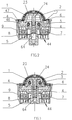
- the present invention is provided with a water-saving flow regulator with flow volume switchable, which has two working states. Normally is the water-saving state, the first flowing passage of the flow regulating device is closed by the switch shaft, water flows out of the second flowing passage.
- the water-saving state is suitable when low flow volume is required.
- high flow volume is required, pushing the switch shaft up, the first flowing passage is open, water flows out of the first and second flowing passage, at this time, it is in high outlet volume that it can achieve high flow volume.
- the present invention is further disposed with a reset device. When in high volume state, with the water pressure pushing upwardly, the switch shaft overcomes the action of the reset device to abut against the water diversion body, the switch shaft would not drop down.
- the tap is turned off, the switch shaft is pushed down by the action of the reset device to return to initial state, at this time, water flows out of only one flowing passage that it achieves forcible water-saving.
- the present invention has less component and smaller size, it can achieve free switch between two outlet states.
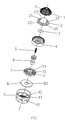
- the filter 1 is a semi-spherical shape with a plurality of throughout holes 11 used to diffuse the water flowing, the lower edge of the filter 1 is disposed with an assembly ring 12.
- the rectifier 7 is plate shaped with a plurality of concentric annular rings 71, a plurality of radial short columns 72 are disposed between the annular rings, a water hole is formed between two adjacent short columns.
- the center of the rectifier is disposed with a second shaft hole to hold the switch shaft 6.
- the center of the flat filter 8 is disposed with a third shaft hole 83 to hold the switch shaft 6.
- the periphery wall of the housing 9 is disposed with a plurality of suction holes 91 with space, the center of the bottom plate at the internal portion of the housing is disposed with a fourth shaft hole 93 to hold the switch shaft 6.
- the bottom plate at the periphery of the fourth shaft hole 93 is disposed with an outlet 92.
- An inlet chamber is formed between the internal wall of the filter 1 and the external periphery surface of the water diversion body 2; an outlet chamber is formed between the lower surface of the hem 25 of the water diversion body and the top surface of the baffle 42 of the inlet body.
Landscapes
- Health & Medical Sciences (AREA)
- Life Sciences & Earth Sciences (AREA)
- Engineering & Computer Science (AREA)
- Hydrology & Water Resources (AREA)
- Public Health (AREA)
- Water Supply & Treatment (AREA)
- Flow Control (AREA)
- Domestic Plumbing Installations (AREA)
- Lift Valve (AREA)
Claims (13)
- Régulateur d'écoulement économiseur d'eau à volume d'écoulement manœuvrable comprenant un boîtier (9) et un dispositif de régulation d'écoulement disposé dans le boîtier (9), le dispositif de régulation d'écoulement comprenant une tige de manœuvre (6), dans lequel le boîtier (9) comprend également un corps de dérivation d'eau (2) disposé au-dessus du dispositif de régulation d'écoulement, le dispositif de régulation d'écoulement est pourvu d'un trou pour tige (44), la tige de manœuvre (6) est insérée dans le trou pour tige (44) ; la périphérie du trou pour tige (44) est pourvue d'une pluralité de trous traversants, les trous traversants forment un deuxième passage d'écoulement, la partie de fond du corps de dérivation d'eau (2) forme une chambre de logement (23), la tige de manœuvre (6) est mobile entre une position initiale et une deuxième position ;
caractérisé en ce qu'un premier passage d'écoulement est formé entre la tige de manœuvre (6) et la paroi de trou pour tige du dispositif de régulation d'écoulement, la tige de manœuvre (6) est gainée avec une pièce d'étanchéité, et en ce que dans la position initiale, la pièce d'étanchéité de la tige de manœuvre (6) ferme le premier passage d'écoulement du dispositif de régulation d'écoulement, l'eau s'écoule seulement du deuxième passage d'écoulement, et dans la deuxième position, la pièce d'étanchéité de la tige de manœuvre (6) quitte le dispositif de régulation d'écoulement, le deuxième passage d'écoulement est ouvert et reste ouvert sous la pression de l'eau, l'eau coule du premier passage d'écoulement et du deuxième passage d'écoulement. - Régulateur d'écoulement économiseur d'eau à volume d'écoulement manœuvrable selon la revendication 1, dans lequel la tige de manœuvre (6) est pourvue d'une grosse extrémité, la grosse extrémité est gainée avec la pièce d'étanchéité.
- Régulateur d'écoulement économiseur d'eau à volume d'écoulement manœuvrable selon la revendication 1, dans lequel le centre du corps de dérivation d'eau (2) est pourvu d'une saillie creuse (21), une pluralité de trous de dérivation d'eau (22) sont disposés au bord de la saillie (21) ; la partie interne de la saillie (21) est pourvue de la chambre de logement (23) avec une ouverture vers le bas, la pièce d'étanchéité de la tige de manœuvre (6) ferme la chambre de logement (23) quand elle entre dans celle-ci.
- Régulateur d'écoulement économiseur d'eau à volume d'écoulement manœuvrable selon la revendication 1, dans lequel le dispositif de régulation d'écoulement comprend un corps d'entrée (4) et un rectifieur (7), le corps d'entrée (4) est disposé à l'orifice d'entrée, le rectifieur (7) est disposé au-dessous du corps d'entrée (4).
- Régulateur d'écoulement économiseur d'eau à volume d'écoulement manœuvrable selon la revendication 4, dans lequel le corps d'entrée (4) comprend une paroi périphérique (41), la partie de fond de la partie interne de la paroi périphérique (41) est pourvue d'un déflecteur (42), une pluralité de trous traversants sont disposés au niveau du déflecteur (42), le centre du déflecteur (42) est pourvu d'un premier trou pour tige (44), le côté du premier trou pour tige (44) tourné vers le corps de dérivation d'eau (2) est pourvu d'un trou à épaulement (45) à diamètre agrandi.
- Régulateur d'écoulement économiseur d'eau à volume d'écoulement manœuvrable selon la revendication 4, dans lequel le rectifieur (7) a la forme d'une plaque avec une pluralité de bagues annulaires concentriques (71), une pluralité de courtes colonnettes radiales (72) sont disposées entre les bagues annulaires (71), un trou d'eau est formé entre deux colonnettes courtes voisines ; le centre du rectifieur (7) est pourvu d'un deuxième trou pour tige (73) pour tenir la tige de manœuvre (6).
- Régulateur d'écoulement économiseur d'eau à volume d'écoulement manœuvrable selon la revendication 1, dans lequel la tige de manœuvre (6) a la forme d'une colonnette, l'extrémité supérieure de tige de manœuvre (6) est pourvue de deux saillies entourant la paroi périphérique (41), une rainure annulaire (63) est formée entre les deux saillies, la pièce d'étanchéité est une bague d'étanchéité (3) assemblée avec la rainure annulaire (63).
- Régulateur d'écoulement économiseur d'eau à volume d'écoulement manœuvrable selon la revendication 1, dans lequel le dispositif de régulation d'écoulement comprend également un filtre plat (8) assemblé avec la partie de sortie du dispositif de régulation d'écoulement, le centre du filtre plat (8) est pourvu d'un troisième trou pour tige (83) pour tenir la tige de manœuvre (6).
- Régulateur d'écoulement économiseur d'eau à volume d'écoulement manœuvrable selon la revendication 1, dans lequel le régulateur d'écoulement comprend un dispositif de rappel de tige de manœuvre (6), le dispositif de rappel de tige de manœuvre (6) comprend un ressort (5), une extrémité du ressort (5) bute contre la tige de manœuvre (6), l'autre extrémité bute contre une partie de fond du corps de dérivation d'eau (2).
- Régulateur d'écoulement économiseur d'eau à volume d'écoulement manœuvrable selon la revendication 9, dans lequel l'axe de la partie d'extrémité de la tige de manœuvre (6) est disposé le long d'une chambre de position de ressort, la chambre de logement (23) de la partie de fond du corps de dérivation d'eau (2) est pourvue d'une colonnette de position (24) insérée dans la chambre de position de ressort ; une extrémité du ressort est disposée dans la chambre de position de ressort de la tige de manœuvre (6), l'autre extrémité bute contre la colonnette de position (24) du corps de dérivation d'eau (2).
- Régulateur d'écoulement économiseur d'eau à volume d'écoulement manœuvrable selon la revendication 3, dans lequel le bord inférieur de la saillie (21) du corps de dérivation d'eau (2) forme un rebord (25), les trous de dérivation d'eau (22) sont disposés à la jonction de la bordure (25) et de la saillie (21), une nervure de renforcement (26) est disposée entre deux trous de dérivation d'eau (22) adjacents ; la partie supérieure de la saillie (21) est une section d'arc (27).
- Régulateur d'écoulement économiseur d'eau à volume d'écoulement manœuvrable selon la revendication 11, dans lequel le dispositif de régulation d'écoulement comprend un corps d'entrée (4) et un rectifieur (7) ; le corps d'entrée (4) comprend une paroi périphérique (41), la partie de fond de la partie interne de la paroi périphérique (41) est pourvue d'un déflecteur (42), le déflecteur (42) est pourvu d'une pluralité de trous traversants (43) ; un épaulement de position (46) et une rainure d'assemblage (47) sont disposés dans la paroi périphérique (41) du corps d'entrée (4) au-dessus du déflecteur (42).
- Régulateur d'écoulement économiseur d'eau à volume d'écoulement manœuvrable selon la revendication 12, dans lequel le dispositif de régulation d'écoulement comprend un filtre (1) et un filtre plat (8) ; le filtre plat (8), le rectifieur (7) et le corps d'entrée (4) sont assemblés dans le boîtier (9) dans cet ordre ; la tige de manœuvre (6) est disposée dans le corps d'entrée (4), la partie inférieure de la tige de manœuvre (6) passe à travers le corps d'entrée (4), le rectifieur (7), le filtre plat (8) et le boîtier (9) dans cet ordre ; le corps de dérivation d'eau (2) est assemblé avec l'épaulement de position (46) du corps d'entrée (4), le filtre est assemblé au-dessus du corps de dérivation d'eau (2), la bague d'assemblage (12) du filtre (1) est encastrée dans la rainure d'assemblage (47) du corps d'entrée (4) ; une chambre d'entrée est formée entre la paroi interne du filtre (1) et la surface périphérique externe du corps de dérivation d'eau (2) ; une chambre de sortie est formée entre la surface inférieure du rebord (25) du corps de dérivation d'eau (2) et la surface supérieure du déflecteur (42) du corps d'entrée (4).
Applications Claiming Priority (3)
| Application Number | Priority Date | Filing Date | Title |
|---|---|---|---|
| CN201310731765.8A CN103696462B (zh) | 2013-12-26 | 2013-12-26 | 一种可切换水量的节水起泡器 |
| CN201320868791.0U CN203625983U (zh) | 2013-12-26 | 2013-12-26 | 一种可切换水量的节水起泡器 |
| PCT/CN2014/094898 WO2015096759A1 (fr) | 2013-12-26 | 2014-12-25 | Barboteur d'économie en eau à débit d'eau réglable |
Publications (3)
| Publication Number | Publication Date |
|---|---|
| EP3088615A1 EP3088615A1 (fr) | 2016-11-02 |
| EP3088615A4 EP3088615A4 (fr) | 2017-08-09 |
| EP3088615B1 true EP3088615B1 (fr) | 2020-02-12 |
Family
ID=53477568
Family Applications (1)
| Application Number | Title | Priority Date | Filing Date |
|---|---|---|---|
| EP14875662.0A Active EP3088615B1 (fr) | 2013-12-26 | 2014-12-25 | Aérateur à débit d'eau réglable |
Country Status (3)
| Country | Link |
|---|---|
| US (1) | US9982423B2 (fr) |
| EP (1) | EP3088615B1 (fr) |
| WO (1) | WO2015096759A1 (fr) |
Families Citing this family (6)
| Publication number | Priority date | Publication date | Assignee | Title |
|---|---|---|---|---|
| SE540044C2 (sv) * | 2015-03-23 | 2018-03-06 | Ngl Teknik I Linkoeping Ab | Ställbar flödesbegränsare för en blandare och ett förfarandeför att ställa flödet |
| WO2017107352A1 (fr) * | 2015-12-23 | 2017-06-29 | 芜湖美的厨卫电器制造有限公司 | Appareil de régulation de débit et chauffe-eau au gaz comprenant celui-ci |
| CZ307612B6 (cs) * | 2017-04-20 | 2019-01-09 | Wavitar s.r.o. | Perlátor |
| CN109610569A (zh) * | 2018-11-27 | 2019-04-12 | 厦门睿晨环境科技有限公司 | 一种双功能自动切换起泡器 |
| TWI722765B (zh) * | 2020-01-16 | 2021-03-21 | 浩瀚國際有限公司 | 切換式省水閥 |
| CN115451228B (zh) * | 2022-10-11 | 2024-08-16 | 中交第一公路勘察设计研究院有限公司 | 一种用于公路桥梁集中排水系统的管径自动调节装置 |
Family Cites Families (20)
| Publication number | Priority date | Publication date | Assignee | Title |
|---|---|---|---|---|
| DE3903800C2 (de) * | 1989-02-09 | 2001-12-06 | Wildfang Dieter Gmbh | Auslaufvorrichtung |
| US5085246A (en) * | 1990-05-22 | 1992-02-04 | Griinke Ralph E | Plural-rate surge-suppressing valve |
| US6131608A (en) * | 1999-06-08 | 2000-10-17 | Lu; Ke-Way | Water flowrate control device |
| US7219690B2 (en) * | 2004-03-11 | 2007-05-22 | Watkins Manufacturing Corporation | Flow control valve |
| US7143997B2 (en) * | 2005-01-03 | 2006-12-05 | Highplus International Co., Ltd. | Plug assembly for a faucet to automatically stop water flow |
| DE202006003342U1 (de) * | 2006-03-01 | 2007-07-05 | Neoperl Gmbh | Strahlregler |
| EP2100200B1 (fr) * | 2006-12-06 | 2011-04-06 | Neoperl GmbH | Régulateur de débit |
| US7677473B2 (en) | 2007-12-28 | 2010-03-16 | Highplus International Co., Ltd. | Spout for foaming and saving water |
| US7950624B2 (en) * | 2008-09-04 | 2011-05-31 | Hui-Fen Liao | Water valve apparatus |
| CN201351764Y (zh) * | 2009-01-10 | 2009-11-25 | 邝溢林 | 一种结构改良的水龙头起泡器 |
| AU2010345682B2 (en) * | 2010-02-12 | 2013-05-30 | Neoperl Ag | Water-saving valve |
| CN201618625U (zh) * | 2010-03-02 | 2010-11-03 | 厦门松霖科技有限公司 | 一种按钮节水花洒 |
| DE102010055459A1 (de) * | 2010-05-27 | 2011-12-01 | Neoperl Gmbh | Sanitärer Auslaufeinsatz |
| CN201972201U (zh) * | 2011-01-20 | 2011-09-14 | 厦门市易洁卫浴有限公司 | 旋转节水起泡器 |
| CN102359154B (zh) | 2011-08-04 | 2013-03-27 | 厦门松霖科技有限公司 | 气水混合起泡器 |
| US9222599B2 (en) * | 2013-02-05 | 2015-12-29 | Highplus International Co., Ltd. | Self-closing water-saving valve assembly |
| CN203625983U (zh) * | 2013-12-26 | 2014-06-04 | 厦门松霖科技有限公司 | 一种可切换水量的节水起泡器 |
| CN103696462B (zh) * | 2013-12-26 | 2015-04-29 | 厦门松霖科技有限公司 | 一种可切换水量的节水起泡器 |
| JP6277835B2 (ja) * | 2014-04-08 | 2018-02-14 | 京三電機株式会社 | 燃料蒸気制御装置 |
| JP6176215B2 (ja) * | 2014-09-25 | 2017-08-09 | 株式会社デンソー | 二段切替弁 |
-
2014
- 2014-12-25 EP EP14875662.0A patent/EP3088615B1/fr active Active
- 2014-12-25 WO PCT/CN2014/094898 patent/WO2015096759A1/fr not_active Ceased
- 2014-12-25 US US15/103,136 patent/US9982423B2/en active Active
Non-Patent Citations (1)
| Title |
|---|
| None * |
Also Published As
| Publication number | Publication date |
|---|---|
| US20160298321A1 (en) | 2016-10-13 |
| US9982423B2 (en) | 2018-05-29 |
| WO2015096759A1 (fr) | 2015-07-02 |
| EP3088615A4 (fr) | 2017-08-09 |
| EP3088615A1 (fr) | 2016-11-02 |
Similar Documents
| Publication | Publication Date | Title |
|---|---|---|
| EP3088615B1 (fr) | Aérateur à débit d'eau réglable | |
| US8757518B2 (en) | Water-saving valve | |
| CN106703132B (zh) | 恒流起泡器 | |
| CN106704700B (zh) | 水龙头省水装置及使用该省水装置的方法 | |
| US20170136476A1 (en) | Concealed flow regulator | |
| US20140300010A1 (en) | Aerator with dual spraying functions | |
| EP3208390A1 (fr) | Régulateur d'écoulement dissimulé | |
| US20150090811A1 (en) | Combined pilot valve mechanism and a shower system applied with the combined pilot valve mechanism | |
| WO2018113129A1 (fr) | Pomme de douche apte à évacuer rapidement l'eau résiduelle | |
| CN103696462B (zh) | 一种可切换水量的节水起泡器 | |
| TWM452280U (zh) | 自閉式省水閥 | |
| CN103821201B (zh) | 带清洁功能的出水装置 | |
| US8857471B2 (en) | Control structure of wall-mounted faucet | |
| CN203625983U (zh) | 一种可切换水量的节水起泡器 | |
| GB2537209A (en) | A water saving mechanism with high flow volume in low pressure | |
| CN107289184A (zh) | 侧推式水阀 | |
| CN205018508U (zh) | 水壶盖 | |
| CN201284859Y (zh) | 进水限流阀 | |
| US20050060800A1 (en) | Control valve for a shower | |
| CN206555557U (zh) | 一种装在水龙头出水管的出水控制组件 | |
| CN103851243B (zh) | 自闭式省水阀 | |
| CN210713073U (zh) | 一种起泡器 | |
| CN206929379U (zh) | 一种按钮式龙头 | |
| CN102302988A (zh) | 一种按摩花洒水整流器 | |
| CN203730826U (zh) | 拨钮切换阀组及出水装置 |
Legal Events
| Date | Code | Title | Description |
|---|---|---|---|
| PUAI | Public reference made under article 153(3) epc to a published international application that has entered the european phase |
Free format text: ORIGINAL CODE: 0009012 |
|
| 17P | Request for examination filed |
Effective date: 20160726 |
|
| AK | Designated contracting states |
Kind code of ref document: A1 Designated state(s): AL AT BE BG CH CY CZ DE DK EE ES FI FR GB GR HR HU IE IS IT LI LT LU LV MC MK MT NL NO PL PT RO RS SE SI SK SM TR |
|
| AX | Request for extension of the european patent |
Extension state: BA ME |
|
| DAX | Request for extension of the european patent (deleted) | ||
| A4 | Supplementary search report drawn up and despatched |
Effective date: 20170710 |
|
| RIC1 | Information provided on ipc code assigned before grant |
Ipc: E03C 1/084 20060101AFI20170704BHEP Ipc: B05B 1/30 20060101ALI20170704BHEP |
|
| RAP1 | Party data changed (applicant data changed or rights of an application transferred) |
Owner name: XIAMEN SOLEX HIGH-TECH INDUSTRIES CO., LTD. Owner name: ZHOU, HUASONG |
|
| RAP1 | Party data changed (applicant data changed or rights of an application transferred) |
Owner name: XIAMEN SOLEX HIGH-TECH INDUSTRIES CO., LTD. |
|
| RAP1 | Party data changed (applicant data changed or rights of an application transferred) |
Owner name: XIAMEN SOLEX HIGH-TECH INDUSTRIES CO., LTD. |
|
| RIC1 | Information provided on ipc code assigned before grant |
Ipc: B05B 1/30 20060101ALI20190710BHEP Ipc: E03C 1/084 20060101AFI20190710BHEP |
|
| GRAP | Despatch of communication of intention to grant a patent |
Free format text: ORIGINAL CODE: EPIDOSNIGR1 |
|
| STAA | Information on the status of an ep patent application or granted ep patent |
Free format text: STATUS: GRANT OF PATENT IS INTENDED |
|
| INTG | Intention to grant announced |
Effective date: 20190819 |
|
| GRAS | Grant fee paid |
Free format text: ORIGINAL CODE: EPIDOSNIGR3 |
|
| GRAA | (expected) grant |
Free format text: ORIGINAL CODE: 0009210 |
|
| STAA | Information on the status of an ep patent application or granted ep patent |
Free format text: STATUS: THE PATENT HAS BEEN GRANTED |
|
| AK | Designated contracting states |
Kind code of ref document: B1 Designated state(s): AL AT BE BG CH CY CZ DE DK EE ES FI FR GB GR HR HU IE IS IT LI LT LU LV MC MK MT NL NO PL PT RO RS SE SI SK SM TR |
|
| REG | Reference to a national code |
Ref country code: GB Ref legal event code: FG4D |
|
| REG | Reference to a national code |
Ref country code: CH Ref legal event code: EP |
|
| REG | Reference to a national code |
Ref country code: AT Ref legal event code: REF Ref document number: 1232276 Country of ref document: AT Kind code of ref document: T Effective date: 20200215 |
|
| REG | Reference to a national code |
Ref country code: IE Ref legal event code: FG4D |
|
| REG | Reference to a national code |
Ref country code: DE Ref legal event code: R096 Ref document number: 602014061067 Country of ref document: DE |
|
| PG25 | Lapsed in a contracting state [announced via postgrant information from national office to epo] |
Ref country code: RS Free format text: LAPSE BECAUSE OF FAILURE TO SUBMIT A TRANSLATION OF THE DESCRIPTION OR TO PAY THE FEE WITHIN THE PRESCRIBED TIME-LIMIT Effective date: 20200212 Ref country code: NO Free format text: LAPSE BECAUSE OF FAILURE TO SUBMIT A TRANSLATION OF THE DESCRIPTION OR TO PAY THE FEE WITHIN THE PRESCRIBED TIME-LIMIT Effective date: 20200512 Ref country code: FI Free format text: LAPSE BECAUSE OF FAILURE TO SUBMIT A TRANSLATION OF THE DESCRIPTION OR TO PAY THE FEE WITHIN THE PRESCRIBED TIME-LIMIT Effective date: 20200212 |
|
| REG | Reference to a national code |
Ref country code: LT Ref legal event code: MG4D |
|
| REG | Reference to a national code |
Ref country code: NL Ref legal event code: MP Effective date: 20200212 |
|
| PG25 | Lapsed in a contracting state [announced via postgrant information from national office to epo] |
Ref country code: SE Free format text: LAPSE BECAUSE OF FAILURE TO SUBMIT A TRANSLATION OF THE DESCRIPTION OR TO PAY THE FEE WITHIN THE PRESCRIBED TIME-LIMIT Effective date: 20200212 Ref country code: LV Free format text: LAPSE BECAUSE OF FAILURE TO SUBMIT A TRANSLATION OF THE DESCRIPTION OR TO PAY THE FEE WITHIN THE PRESCRIBED TIME-LIMIT Effective date: 20200212 Ref country code: IS Free format text: LAPSE BECAUSE OF FAILURE TO SUBMIT A TRANSLATION OF THE DESCRIPTION OR TO PAY THE FEE WITHIN THE PRESCRIBED TIME-LIMIT Effective date: 20200612 Ref country code: HR Free format text: LAPSE BECAUSE OF FAILURE TO SUBMIT A TRANSLATION OF THE DESCRIPTION OR TO PAY THE FEE WITHIN THE PRESCRIBED TIME-LIMIT Effective date: 20200212 Ref country code: BG Free format text: LAPSE BECAUSE OF FAILURE TO SUBMIT A TRANSLATION OF THE DESCRIPTION OR TO PAY THE FEE WITHIN THE PRESCRIBED TIME-LIMIT Effective date: 20200512 Ref country code: GR Free format text: LAPSE BECAUSE OF FAILURE TO SUBMIT A TRANSLATION OF THE DESCRIPTION OR TO PAY THE FEE WITHIN THE PRESCRIBED TIME-LIMIT Effective date: 20200513 |
|
| PG25 | Lapsed in a contracting state [announced via postgrant information from national office to epo] |
Ref country code: NL Free format text: LAPSE BECAUSE OF FAILURE TO SUBMIT A TRANSLATION OF THE DESCRIPTION OR TO PAY THE FEE WITHIN THE PRESCRIBED TIME-LIMIT Effective date: 20200212 |
|
| PG25 | Lapsed in a contracting state [announced via postgrant information from national office to epo] |
Ref country code: SK Free format text: LAPSE BECAUSE OF FAILURE TO SUBMIT A TRANSLATION OF THE DESCRIPTION OR TO PAY THE FEE WITHIN THE PRESCRIBED TIME-LIMIT Effective date: 20200212 Ref country code: PT Free format text: LAPSE BECAUSE OF FAILURE TO SUBMIT A TRANSLATION OF THE DESCRIPTION OR TO PAY THE FEE WITHIN THE PRESCRIBED TIME-LIMIT Effective date: 20200705 Ref country code: LT Free format text: LAPSE BECAUSE OF FAILURE TO SUBMIT A TRANSLATION OF THE DESCRIPTION OR TO PAY THE FEE WITHIN THE PRESCRIBED TIME-LIMIT Effective date: 20200212 Ref country code: SM Free format text: LAPSE BECAUSE OF FAILURE TO SUBMIT A TRANSLATION OF THE DESCRIPTION OR TO PAY THE FEE WITHIN THE PRESCRIBED TIME-LIMIT Effective date: 20200212 Ref country code: EE Free format text: LAPSE BECAUSE OF FAILURE TO SUBMIT A TRANSLATION OF THE DESCRIPTION OR TO PAY THE FEE WITHIN THE PRESCRIBED TIME-LIMIT Effective date: 20200212 Ref country code: DK Free format text: LAPSE BECAUSE OF FAILURE TO SUBMIT A TRANSLATION OF THE DESCRIPTION OR TO PAY THE FEE WITHIN THE PRESCRIBED TIME-LIMIT Effective date: 20200212 Ref country code: RO Free format text: LAPSE BECAUSE OF FAILURE TO SUBMIT A TRANSLATION OF THE DESCRIPTION OR TO PAY THE FEE WITHIN THE PRESCRIBED TIME-LIMIT Effective date: 20200212 Ref country code: CZ Free format text: LAPSE BECAUSE OF FAILURE TO SUBMIT A TRANSLATION OF THE DESCRIPTION OR TO PAY THE FEE WITHIN THE PRESCRIBED TIME-LIMIT Effective date: 20200212 Ref country code: ES Free format text: LAPSE BECAUSE OF FAILURE TO SUBMIT A TRANSLATION OF THE DESCRIPTION OR TO PAY THE FEE WITHIN THE PRESCRIBED TIME-LIMIT Effective date: 20200212 |
|
| REG | Reference to a national code |
Ref country code: DE Ref legal event code: R097 Ref document number: 602014061067 Country of ref document: DE |
|
| REG | Reference to a national code |
Ref country code: AT Ref legal event code: MK05 Ref document number: 1232276 Country of ref document: AT Kind code of ref document: T Effective date: 20200212 |
|
| PLBE | No opposition filed within time limit |
Free format text: ORIGINAL CODE: 0009261 |
|
| STAA | Information on the status of an ep patent application or granted ep patent |
Free format text: STATUS: NO OPPOSITION FILED WITHIN TIME LIMIT |
|
| 26N | No opposition filed |
Effective date: 20201113 |
|
| PG25 | Lapsed in a contracting state [announced via postgrant information from national office to epo] |
Ref country code: AT Free format text: LAPSE BECAUSE OF FAILURE TO SUBMIT A TRANSLATION OF THE DESCRIPTION OR TO PAY THE FEE WITHIN THE PRESCRIBED TIME-LIMIT Effective date: 20200212 Ref country code: IT Free format text: LAPSE BECAUSE OF FAILURE TO SUBMIT A TRANSLATION OF THE DESCRIPTION OR TO PAY THE FEE WITHIN THE PRESCRIBED TIME-LIMIT Effective date: 20200212 |
|
| PG25 | Lapsed in a contracting state [announced via postgrant information from national office to epo] |
Ref country code: SI Free format text: LAPSE BECAUSE OF FAILURE TO SUBMIT A TRANSLATION OF THE DESCRIPTION OR TO PAY THE FEE WITHIN THE PRESCRIBED TIME-LIMIT Effective date: 20200212 Ref country code: PL Free format text: LAPSE BECAUSE OF FAILURE TO SUBMIT A TRANSLATION OF THE DESCRIPTION OR TO PAY THE FEE WITHIN THE PRESCRIBED TIME-LIMIT Effective date: 20200212 |
|
| REG | Reference to a national code |
Ref country code: CH Ref legal event code: PL |
|
| GBPC | Gb: european patent ceased through non-payment of renewal fee |
Effective date: 20201225 |
|
| PG25 | Lapsed in a contracting state [announced via postgrant information from national office to epo] |
Ref country code: MC Free format text: LAPSE BECAUSE OF FAILURE TO SUBMIT A TRANSLATION OF THE DESCRIPTION OR TO PAY THE FEE WITHIN THE PRESCRIBED TIME-LIMIT Effective date: 20200212 |
|
| REG | Reference to a national code |
Ref country code: BE Ref legal event code: MM Effective date: 20201231 |
|
| PG25 | Lapsed in a contracting state [announced via postgrant information from national office to epo] |
Ref country code: FR Free format text: LAPSE BECAUSE OF NON-PAYMENT OF DUE FEES Effective date: 20201231 Ref country code: LU Free format text: LAPSE BECAUSE OF NON-PAYMENT OF DUE FEES Effective date: 20201225 Ref country code: IE Free format text: LAPSE BECAUSE OF NON-PAYMENT OF DUE FEES Effective date: 20201225 |
|
| PG25 | Lapsed in a contracting state [announced via postgrant information from national office to epo] |
Ref country code: CH Free format text: LAPSE BECAUSE OF NON-PAYMENT OF DUE FEES Effective date: 20201231 Ref country code: GB Free format text: LAPSE BECAUSE OF NON-PAYMENT OF DUE FEES Effective date: 20201225 Ref country code: LI Free format text: LAPSE BECAUSE OF NON-PAYMENT OF DUE FEES Effective date: 20201231 |
|
| PGFP | Annual fee paid to national office [announced via postgrant information from national office to epo] |
Ref country code: DE Payment date: 20211231 Year of fee payment: 8 |
|
| PG25 | Lapsed in a contracting state [announced via postgrant information from national office to epo] |
Ref country code: MT Free format text: LAPSE BECAUSE OF FAILURE TO SUBMIT A TRANSLATION OF THE DESCRIPTION OR TO PAY THE FEE WITHIN THE PRESCRIBED TIME-LIMIT Effective date: 20200212 Ref country code: CY Free format text: LAPSE BECAUSE OF FAILURE TO SUBMIT A TRANSLATION OF THE DESCRIPTION OR TO PAY THE FEE WITHIN THE PRESCRIBED TIME-LIMIT Effective date: 20200212 |
|
| PG25 | Lapsed in a contracting state [announced via postgrant information from national office to epo] |
Ref country code: MK Free format text: LAPSE BECAUSE OF FAILURE TO SUBMIT A TRANSLATION OF THE DESCRIPTION OR TO PAY THE FEE WITHIN THE PRESCRIBED TIME-LIMIT Effective date: 20200212 Ref country code: AL Free format text: LAPSE BECAUSE OF FAILURE TO SUBMIT A TRANSLATION OF THE DESCRIPTION OR TO PAY THE FEE WITHIN THE PRESCRIBED TIME-LIMIT Effective date: 20200212 |
|
| PG25 | Lapsed in a contracting state [announced via postgrant information from national office to epo] |
Ref country code: BE Free format text: LAPSE BECAUSE OF NON-PAYMENT OF DUE FEES Effective date: 20201231 |
|
| REG | Reference to a national code |
Ref country code: DE Ref legal event code: R119 Ref document number: 602014061067 Country of ref document: DE |
|
| PG25 | Lapsed in a contracting state [announced via postgrant information from national office to epo] |
Ref country code: DE Free format text: LAPSE BECAUSE OF NON-PAYMENT OF DUE FEES Effective date: 20230701 |
|
| PG25 | Lapsed in a contracting state [announced via postgrant information from national office to epo] |
Ref country code: TR Free format text: LAPSE BECAUSE OF NON-PAYMENT OF DUE FEES Effective date: 20201225 |