EP3088645B1 - Dispositif de liaison pour une porte coulissante - Google Patents
Dispositif de liaison pour une porte coulissante Download PDFInfo
- Publication number
- EP3088645B1 EP3088645B1 EP15165291.4A EP15165291A EP3088645B1 EP 3088645 B1 EP3088645 B1 EP 3088645B1 EP 15165291 A EP15165291 A EP 15165291A EP 3088645 B1 EP3088645 B1 EP 3088645B1
- Authority
- EP
- European Patent Office
- Prior art keywords
- plate
- flange
- coupling
- mounting
- mounting plate
- Prior art date
- Legal status (The legal status is an assumption and is not a legal conclusion. Google has not performed a legal analysis and makes no representation as to the accuracy of the status listed.)
- Active
Links
Images


Classifications
-
- E—FIXED CONSTRUCTIONS
- E06—DOORS, WINDOWS, SHUTTERS, OR ROLLER BLINDS IN GENERAL; LADDERS
- E06B—FIXED OR MOVABLE CLOSURES FOR OPENINGS IN BUILDINGS, VEHICLES, FENCES OR LIKE ENCLOSURES IN GENERAL, e.g. DOORS, WINDOWS, BLINDS, GATES
- E06B3/00—Window sashes, door leaves, or like elements for closing wall or like openings; Layout of fixed or moving closures, e.g. windows in wall or like openings; Features of rigidly-mounted outer frames relating to the mounting of wing frames
- E06B3/32—Arrangements of wings characterised by the manner of movement; Arrangements of movable wings in openings; Features of wings or frames relating solely to the manner of movement of the wing
- E06B3/34—Arrangements of wings characterised by the manner of movement; Arrangements of movable wings in openings; Features of wings or frames relating solely to the manner of movement of the wing with only one kind of movement
- E06B3/42—Sliding wings; Details of frames with respect to guiding
- E06B3/46—Horizontally-sliding wings
- E06B3/4663—Horizontally-sliding wings specially adapted for furniture
-
- E—FIXED CONSTRUCTIONS
- E05—LOCKS; KEYS; WINDOW OR DOOR FITTINGS; SAFES
- E05D—HINGES OR SUSPENSION DEVICES FOR DOORS, WINDOWS OR WINGS
- E05D15/00—Suspension arrangements for wings
- E05D15/06—Suspension arrangements for wings for wings sliding horizontally more or less in their own plane
- E05D15/10—Suspension arrangements for wings for wings sliding horizontally more or less in their own plane movable out of one plane into a second parallel plane
-
- A—HUMAN NECESSITIES
- A47—FURNITURE; DOMESTIC ARTICLES OR APPLIANCES; COFFEE MILLS; SPICE MILLS; SUCTION CLEANERS IN GENERAL
- A47B—TABLES; DESKS; OFFICE FURNITURE; CABINETS; DRAWERS; GENERAL DETAILS OF FURNITURE
- A47B61/00—Wardrobes
-
- E—FIXED CONSTRUCTIONS
- E05—LOCKS; KEYS; WINDOW OR DOOR FITTINGS; SAFES
- E05D—HINGES OR SUSPENSION DEVICES FOR DOORS, WINDOWS OR WINGS
- E05D15/00—Suspension arrangements for wings
- E05D15/06—Suspension arrangements for wings for wings sliding horizontally more or less in their own plane
- E05D15/0621—Details, e.g. suspension or supporting guides
- E05D15/066—Details, e.g. suspension or supporting guides for wings supported at the bottom
- E05D15/0665—Details, e.g. suspension or supporting guides for wings supported at the bottom on wheels with fixed axis
-
- E—FIXED CONSTRUCTIONS
- E05—LOCKS; KEYS; WINDOW OR DOOR FITTINGS; SAFES
- E05D—HINGES OR SUSPENSION DEVICES FOR DOORS, WINDOWS OR WINGS
- E05D15/00—Suspension arrangements for wings
- E05D15/06—Suspension arrangements for wings for wings sliding horizontally more or less in their own plane
- E05D15/0621—Details, e.g. suspension or supporting guides
- E05D15/066—Details, e.g. suspension or supporting guides for wings supported at the bottom
- E05D15/0665—Details, e.g. suspension or supporting guides for wings supported at the bottom on wheels with fixed axis
- E05D15/0669—Details, e.g. suspension or supporting guides for wings supported at the bottom on wheels with fixed axis with height adjustment
-
- E—FIXED CONSTRUCTIONS
- E05—LOCKS; KEYS; WINDOW OR DOOR FITTINGS; SAFES
- E05D—HINGES OR SUSPENSION DEVICES FOR DOORS, WINDOWS OR WINGS
- E05D15/00—Suspension arrangements for wings
- E05D15/06—Suspension arrangements for wings for wings sliding horizontally more or less in their own plane
- E05D15/10—Suspension arrangements for wings for wings sliding horizontally more or less in their own plane movable out of one plane into a second parallel plane
- E05D2015/1026—Suspension arrangements for wings for wings sliding horizontally more or less in their own plane movable out of one plane into a second parallel plane accessories, e.g. sliding or rolling guides, latches
-
- E—FIXED CONSTRUCTIONS
- E05—LOCKS; KEYS; WINDOW OR DOOR FITTINGS; SAFES
- E05D—HINGES OR SUSPENSION DEVICES FOR DOORS, WINDOWS OR WINGS
- E05D15/00—Suspension arrangements for wings
- E05D15/06—Suspension arrangements for wings for wings sliding horizontally more or less in their own plane
- E05D15/10—Suspension arrangements for wings for wings sliding horizontally more or less in their own plane movable out of one plane into a second parallel plane
- E05D2015/1028—Suspension arrangements for wings for wings sliding horizontally more or less in their own plane movable out of one plane into a second parallel plane with only the wing moving transversely
- E05D2015/1031—Suspension arrangements for wings for wings sliding horizontally more or less in their own plane movable out of one plane into a second parallel plane with only the wing moving transversely the wing supported on arms extending from the carriage
-
- E—FIXED CONSTRUCTIONS
- E05—LOCKS; KEYS; WINDOW OR DOOR FITTINGS; SAFES
- E05Y—INDEXING SCHEME ASSOCIATED WITH SUBCLASSES E05D AND E05F, RELATING TO CONSTRUCTION ELEMENTS, ELECTRIC CONTROL, POWER SUPPLY, POWER SIGNAL OR TRANSMISSION, USER INTERFACES, MOUNTING OR COUPLING, DETAILS, ACCESSORIES, AUXILIARY OPERATIONS NOT OTHERWISE PROVIDED FOR, APPLICATION THEREOF
- E05Y2201/00—Constructional elements; Accessories therefor
- E05Y2201/60—Suspension or transmission members; Accessories therefor
- E05Y2201/622—Suspension or transmission members elements
- E05Y2201/696—Screw mechanisms
-
- E—FIXED CONSTRUCTIONS
- E05—LOCKS; KEYS; WINDOW OR DOOR FITTINGS; SAFES
- E05Y—INDEXING SCHEME ASSOCIATED WITH SUBCLASSES E05D AND E05F, RELATING TO CONSTRUCTION ELEMENTS, ELECTRIC CONTROL, POWER SUPPLY, POWER SIGNAL OR TRANSMISSION, USER INTERFACES, MOUNTING OR COUPLING, DETAILS, ACCESSORIES, AUXILIARY OPERATIONS NOT OTHERWISE PROVIDED FOR, APPLICATION THEREOF
- E05Y2600/00—Mounting or coupling arrangements for elements provided for in this subclass
- E05Y2600/10—Adjustable
-
- E—FIXED CONSTRUCTIONS
- E05—LOCKS; KEYS; WINDOW OR DOOR FITTINGS; SAFES
- E05Y—INDEXING SCHEME ASSOCIATED WITH SUBCLASSES E05D AND E05F, RELATING TO CONSTRUCTION ELEMENTS, ELECTRIC CONTROL, POWER SUPPLY, POWER SIGNAL OR TRANSMISSION, USER INTERFACES, MOUNTING OR COUPLING, DETAILS, ACCESSORIES, AUXILIARY OPERATIONS NOT OTHERWISE PROVIDED FOR, APPLICATION THEREOF
- E05Y2600/00—Mounting or coupling arrangements for elements provided for in this subclass
- E05Y2600/10—Adjustable
- E05Y2600/30—Adjustment motion
- E05Y2600/31—Linear motion
- E05Y2600/312—Horizontal motion
-
- E—FIXED CONSTRUCTIONS
- E05—LOCKS; KEYS; WINDOW OR DOOR FITTINGS; SAFES
- E05Y—INDEXING SCHEME ASSOCIATED WITH SUBCLASSES E05D AND E05F, RELATING TO CONSTRUCTION ELEMENTS, ELECTRIC CONTROL, POWER SUPPLY, POWER SIGNAL OR TRANSMISSION, USER INTERFACES, MOUNTING OR COUPLING, DETAILS, ACCESSORIES, AUXILIARY OPERATIONS NOT OTHERWISE PROVIDED FOR, APPLICATION THEREOF
- E05Y2600/00—Mounting or coupling arrangements for elements provided for in this subclass
- E05Y2600/10—Adjustable
- E05Y2600/30—Adjustment motion
- E05Y2600/31—Linear motion
- E05Y2600/314—Vertical motion
-
- E—FIXED CONSTRUCTIONS
- E05—LOCKS; KEYS; WINDOW OR DOOR FITTINGS; SAFES
- E05Y—INDEXING SCHEME ASSOCIATED WITH SUBCLASSES E05D AND E05F, RELATING TO CONSTRUCTION ELEMENTS, ELECTRIC CONTROL, POWER SUPPLY, POWER SIGNAL OR TRANSMISSION, USER INTERFACES, MOUNTING OR COUPLING, DETAILS, ACCESSORIES, AUXILIARY OPERATIONS NOT OTHERWISE PROVIDED FOR, APPLICATION THEREOF
- E05Y2600/00—Mounting or coupling arrangements for elements provided for in this subclass
- E05Y2600/10—Adjustable
- E05Y2600/30—Adjustment motion
- E05Y2600/32—Rotary motion
- E05Y2600/322—Rotary motion around a horizontal axis
-
- E—FIXED CONSTRUCTIONS
- E05—LOCKS; KEYS; WINDOW OR DOOR FITTINGS; SAFES
- E05Y—INDEXING SCHEME ASSOCIATED WITH SUBCLASSES E05D AND E05F, RELATING TO CONSTRUCTION ELEMENTS, ELECTRIC CONTROL, POWER SUPPLY, POWER SIGNAL OR TRANSMISSION, USER INTERFACES, MOUNTING OR COUPLING, DETAILS, ACCESSORIES, AUXILIARY OPERATIONS NOT OTHERWISE PROVIDED FOR, APPLICATION THEREOF
- E05Y2900/00—Application of doors, windows, wings or fittings thereof
- E05Y2900/20—Application of doors, windows, wings or fittings thereof for furniture, e.g. cabinets
Definitions
- the invention relates to a connecting device for sliding doors, in particular for sliding doors of a piece of furniture, which are held displaceably by a guide device and a piece of furniture, in particular a cabinet, with at least one sliding door, which is held by means of this connecting device.
- a disadvantage of cabinets with sliding doors of this type is that the sliding doors must be precisely aligned in order to avoid collisions during the shift and to produce a favorable appearance.
- Known connection devices do not allow it to adjust the sliding doors held in a simple manner.
- adjustable devices with mutually displaceable parts are known, which often have to be solved first before they can be adjusted.
- Such devices are typically designed consuming and also not easily adjustable, since after a mutual displacement and the subsequent mutual fixing of the device parts often turns out that a readjustment is required.
- the US1105918A discloses an adjustable suspension device for barn doors.
- the US6698138B1 discloses a suspension for sliding doors, which is connected on the one hand with the sliding door and on already displaceable with a drive and fixable.
- the present invention is therefore based on the object to provide an improved connection device and a piece of furniture, in particular a cabinet, with at least one sliding door, which is held by means of such a connection device.
- a connecting device is to be provided, which makes it possible to adjust a sliding door held by the connecting device, or generally a flat separating element, at least in height and lateral position, and preferably also in inclination.
- the connecting device should be simple and take up little space. Furthermore, the connecting device should be adjustable even after their installation in a simple manner.
- the sliding doors of a cabinet which are held by means of one or two connecting devices should therefore be adjustable so that they can be aligned flush with respect to the edges and the front surfaces and occupy desired positions and mutual distances in the end positions.
- the connecting device comprises a mounting plate, which is screwed on the one hand by mounting screws with a sliding door and on the other hand connected to a drive device.
- a connecting plate is provided which is arranged between the mounting plate and a coupling plate which can be connected to the drive device.
- the connecting plate is displaceable by first connecting elements in a first direction and connected by a first adjusting screw in a selected displacement position lockable with the mounting plate.
- the coupling plate is displaceable by second connecting elements in a second direction and connected by a second adjusting screw in a selected displacement position lockable with the connecting plate.
- the connecting plate is connected by the first connecting elements with the mounting plate and slidably held in a first direction, preferably horizontally, relative to the mounting plate.
- the coupling plate is connected by the second connecting elements with the connecting plate and slidably held in a second direction, preferably vertically, relative to the connecting plate.
- the first and second connecting elements are for example held in longitudinal slots connecting bolts, rivets or Flange elements that engage in corresponding grooves or overlap corresponding flange elements.
- the mounting plate on the top and bottom on a respective retaining groove into which the connecting plate is slidable so that the edges of the connecting plate engage in the retaining grooves.
- the use of connecting screws or rivets, which are guided through longitudinal slots in the connecting plate and in receiving openings, eg threaded holes, engage in the mounting plate, or connecting screws or rivets, which are guided through longitudinal slots in the coupling plate and in receiving openings, such as threaded holes, Intervene in the connection plate, is particularly easy to implement.
- the mounting plate and / or the connecting plate and / or the coupling plate are preferably made of steel, sheet steel or zinc die-cast. The production by means of die-cast zinc allows the play-free adjacent plates to move against each other without much effort.
- the first and second longitudinal slots are aligned obliquely or perpendicular to each other in accordance with the planned displacement directions.
- connection of the mounting plate and the connecting plate by means of the first adjusting screw and the connection of the coupling plate to the connecting plate by means of the second adjusting screw can each be done in different ways.
- parts of the mounting plate, the connecting plate and the coupling plate are formed as flange elements, which are connected in pairs by the first adjusting screw or by the second adjusting screw and pushed against each other or apart.
- flange elements may advantageously be partially cut out by cuts from the mounting plate, the connecting plate or the coupling plate and bent by 90 °, so that they are aligned parallel to each other.
- Flange elements which bear the load of the associated sliding door wholly or partly, can also with stabilizing elements, e.g. Stabilizing ribs to be connected.
- the mounting plate preferably has a mounting flange, which is preferably provided with a threaded bore, and the connecting plate has a first connecting flange, which is preferably provided with a first retaining element.
- the first adjusting screw can therefore be inserted into the first retaining element on the connecting flange and screwed into the mounting flange.
- the first adjusting screw below the screw head preferably has a collar, so that the e.g. fork-shaped first holding element between the screw head and the collar engage and can capture the screw shaft.
- the first adjusting screw is therefore rotatably held by the connecting flange, but not axially displaceable.
- the connecting plate preferably has a second connecting flange and the coupling plate has a coupling flange, which is preferably provided with a second holding element.
- the second adjusting screw can therefore be inserted into the second retaining element on the coupling flange and screwed into the second connecting flange become.
- the second adjusting screw below the screw head preferably has a collar, so that, for example, fork-shaped configured second holding element between the screw head and the collar and can capture the screw shaft.
- the second adjusting screw is therefore rotatably supported by the coupling flange, but not axially displaceable.
- a third adjusting screw is provided, by means of which the mounting plate or a part thereof relative to the coupling plate is rotatable or by means of which the coupling plate or a part thereof with respect to the mounting plate is rotatable.
- the second and the third adjusting screw By means of the first, the second and the third adjusting screw, it is thus possible to align two sliding doors in height, the lateral position and the inclination against each other. All adjustments can be made conveniently on the connection device.
- the second and the third adjusting screw are arranged on the same side of the connecting device.
- the connecting device is arranged on the underside of the sliding door such that the second and the third adjusting screw are accessible below the sliding door. Below the sliding door, to the rear offset, the second and the third adjustment screw are not visible by the user, but can be easily achieved by the installer. On the installation of a panel on the side of the sliding door, on which the connecting device is arranged, can therefore be omitted.
- the third adjusting screw is held in a threaded bore of a Justierflansches, which is provided on the mounting plate such that the third adjusting screw is rotatable against a stop member which is provided on the connecting plate or on the coupling plate.
- the mounting plate, the connecting plate or the coupling plate preferably has a hinge about which the mounting plate or the coupling plate or the part thereof is rotatable in the operation of the third adjusting screw.
- the joint is preferably a bending joint, followed by at least one incision. That is, preferably, a part of the mounting plate, the connecting plate, or the coupling plate is dimensioned to form a bending zone that is deformable upon rotation of the third adjusting screw, so that a part of the mounting plate or the coupling plate is rotatable by the desired amount.
- the mounting plate, the connecting plate and / or the coupling plate are preferably formed substantially symmetrical.
- the mounting plate and the connecting plate are therefore preferably equipped on both sides with corresponding flange elements, in which the first adjusting screw can be used.
- the connection device can be attached to the left, right or in the middle of a sliding door and adjusted.
- the first adjusting screw is inserted in the connecting flange and the mounting flange, which is the closer edge of the Sliding door is facing, so that the first adjustment screw can be easily detected and rotated.
- the mounting plate, the connecting plate and / or the coupling plate are preferably cut or stamped from a metal plate and provided with the necessary openings, slots and cuts, which allow to bend the flange elements and insert the connecting screws and mounting screws. In this way, the mounting plate and the connection data can be manufactured in a simple manner.
- the coupling plate is preferably provided with the said stabilizing ribs, by means of which the coupling flange is stabilized, in which preferably also the mounting screws provided for connection to the drive device are inserted.
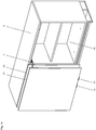
- Fig. 1a shows a cabinet 9 with two of connecting devices 10, 10 'and a complementary guide 6 held sliding doors 91, 92.
- the sliding doors 91, 92 can each be completed a cabinet opening 90.
- the first sliding door 91 was moved away and the associated cabinet opening 90 thereby exposed.
- the first sliding door 91 could be moved laterally over the second sliding door 92, two motion operations were completed.
- the first sliding door 91 was lifted from the cabinet opening 90 to the front and only laterally moved over the second sliding door 92 in the second movement process.
- the guide rails in which the drive 8A connected to the first sliding door 91 see FIG Fig.
- the second sliding door 92 can be moved in the same way on the first sliding door 91.
- the drives are provided on the underside of the cabinet 9. At the top of the cabinet 9, the sliding doors 91, 92 are each held by a complementary guide 9 and guided parallel to the bottom.
- Fig. 1a shows that the two superimposed sliding doors 91, 92 precise, ie flush and parallel aligned with each other. This not only allows the proper movement function of the two sliding doors 91, 92, but also gives an aesthetically advantageous impression. Since during installation of the drives and the guide devices within the cabinet 9 and during installation of the sliding doors 91, 92 regularly slight deviations from ideal positions occur, it is necessary to be able to make corresponding adjustments of the sliding doors 91, 92. In order not to have to intervene in the cabinet 9, for example, to adjust the drive devices, for mounting the sliding doors 91, 92 according to the invention connecting devices 10, 10 'are provided, which allow to perform all necessary adjustments.
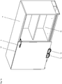
- Fig. 1b shows the cabinet 9 of Fig. 1a after the first sliding door 91 has been released from the associated connection devices 10, 10 'and the complementary guide 6. It can be seen that in the present embodiment of the cabinet 9, two identical connecting devices 10, 10 'are provided for mounting the sliding door 91. If sliding doors with reduced weight are used, a single connection device 10 can also be used.
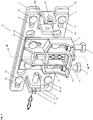
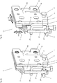
- Fig. 2 shows one of the connecting devices 10 of Fig. 1a in an exploded view with a mounting plate 1, which is connectable via a connecting plate 2 with a coupling plate 3 and the mounting holes 18, can be passed through the mounting screws 99, by means of which the connecting device 10 can be mounted on a sliding door 91.
- the connecting plate 2 each have an associated passage opening 28 whose size is selected such that the mounting screws 99 also after the mutual displacement the mounting plate 1 and the connecting plate 2 are accessible and that the displacement of the connecting plate 2 is not hindered if the mounting screws 99 are not sunk in the mounting plate 1.
- the coupling plate 3 is provided with two coupling screws 71.
- Fig. 3 shows the assembled connection device 10 of Fig. 2 after the mutual horizontal displacement of the mounting plate 1 and the connecting plate 2 and the mutual vertical displacement of the coupling plate 3 and the connecting plate. 2
- connection device 10 The description of the connection device 10 will be made below with reference to FIG Fig. 2 and Fig. 3 ,
- the at least approximately rectangular mounting plate 1 has in the four corner areas receiving openings, e.g. Threaded holes 14, in the first connecting bolts or rivets 41 are inserted, which are guided through horizontally oriented longitudinal slots 24 in corner regions of the at least approximately rectangular connecting plate 2 therethrough.
- the displacement range is defined by the length of the longitudinal slots 24.
- the mounting plate 1 comprises on both sides each a mounting flange 11 which has been cut out of the mounting plate 1 and bent by 90 ° against the connecting plate 2 and which has a fork-shaped holding element 111.
- the connecting plate 2 comprises on both sides each a first connecting flange 21 which has been cut out of the connecting plate 2 and bent by 90 ° against the coupling plate 3 and which is provided with a threaded bore in the a first adjusting screw 12 is inserted.
- the first adjusting screw 12 which has a screw head and a collar 121 underneath, can be inserted into the fork-shaped holding element 111 of the corresponding mounting flange 11.
- the mounting plate 1 and the connecting plate 2 which are connected by the first connecting bolts or rivets 41 slidably interconnected, therefore, by means of the first adjusting screw 12 against each other or pushed apart and remain held by the first adjusting screw 12 in a selected position.
- the first adjusting screw 12 can be connected on one or the other side with the local mounting flange 11 and the first connecting flange 21.
- the first adjustment screw 12 can be removed on the left side and inserted on the right side if the connection device 10 is mounted on the right edge of the sliding door.
- the connecting plate 2 comprises a second connecting flange 22, which has been cut out of the connecting plate 2 and bent by 90 ° against the coupling plate 3.
- the connecting plate 2 also has four receiving openings, for example threaded bores 26, into which second connecting screws or rivets 42 are inserted, which are guided through vertically aligned longitudinal slots 34 in the connecting plate 2.
- the displacement range is defined by the length of the longitudinal slots 34.
- the coupling plate 3 also has a coupling flange 31 with a second holding element 311 or a U-shaped recess, to which a window opening 35 in the coupling plate 3 adjoins.
- the window opening 35 serves to receive the second connecting flange 22, which is guided parallel to the coupling flange 31 through the window opening 35 and vertically displaceable therein.
- the coupling flange 31 further serves to hold the coupling screws 71.
- a second adjusting screw 23 is mounted, which has a screw head and a collar 231 below.
- the shaft of the second adjusting screw 23, however, is rotatably supported in the second connecting flange 22 in a threaded bore.
- the mounting plate 1 and the coupling plate 3 can therefore be moved horizontally and vertically against each other.
- the inclination of the coupling plate 3 with respect to the mounting plate 1 can be adjusted.
- the two wing elements 16 are formed by the two lower corners of the mounting plate 1, which are separated by a respective recess 19 from the mounting body 17.
- the two wing elements 16 are therefore only over the joints or bending zones 190 connected to the mounting body 17, so that they can be bent with a corresponding force or by rotation of a third adjusting screw 13 (see Fig. 5b ).
- the mounting plate of Fig. 2 On the bottom of a Justierflansch 15, which is provided with a threaded bore 150.
- the held in the threaded bore 150 third adjusting screw 13 is rotatable against a stop member 25 on the connecting plate 2.
- the underside of the connecting plate 2 is pushed forward together with the coupling plate 3 in the sequence.
- the wing members 16 rotate together with the connecting plate 2 to the joints 190.
- the mounting plate 1 usually to the required elasticity, so that the wing elements 16 act with a counter force on the third adjusting screw 13 and this always rests without play on the stop member 25.
- Fig. 3 shows the assembled connecting device 10 after an actuation of the first adjusting screw 12 and the second adjusting screw 23.
- the connecting plate 2 By operating the first adjusting screw 12, the connecting plate 2 has been moved with the coupling plate 3 relative to the mounting plate 1 to the left.
- the coupling plate 3 By rotation of the second adjusting screw 23, the coupling plate 3 has been moved relative to the mounting plate 1 and the connecting plate 2 down.
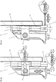
- Fig. 4a shows a section through the connecting device 10 of Fig. 3 along the line A - A in front of a mutual Displacement of the mounting plate 1, the connecting plate 2 and the coupling plate 3.
- the coupling flange 31, held by the coupling flange 31 second adjusting screw 23 (shown in section) and the window opening 35 in the coupling plate 3, in which the second connecting flange 22 protrudes shown.
- the third adjusting screw 13 inserted in the adjusting flange 15 is shown, which is preferably designed as a threaded pin 13.
- the wing member 16 is shown, which is partially separated by a recess 19 from the mounting body 17 of the mounting plate 1 and connected via a flexure 190 with this. By rotating the third adjusting screw 13, the mounting body 17 can therefore be rotated relative to the wing element 16.
- Fig. 4b shows a section through the connecting device 10 of Fig. 3 along the line A - A with subsequent mutual displacement of the mounting plate 1, the connecting plate 2 and the coupling plate 3.
- the mounting plate 1 and the connecting plate 2 were moved horizontally against each other.
- the coupling plate 3 was shifted vertically downward with respect to the connecting plate 2.
- Fig. 5a shows the connecting device 10 of Fig. 3 from the side during the adjustment for the horizontal mutual displacement of the mounting plate 1 and the connecting plate 2 by rotation of the first adjusting screw 12 and the vertical mutual displacement of the coupling plate 3 and the connecting plate 2 by rotation of the second adjusting screw 23rd
- Fig. 5b shows the connecting device 10 of Fig. 5a during adjustment for adjusting the inclination of the coupling plate 3 relative to the mounting plate 1 by rotation the third adjusting screw 13, which is used as a threaded pin in the mounting plate 1.
- the third adjusting screw 13 By rotation of the third adjusting screw 13, the inclination of the door leaf of the first sliding door 91 can be adjusted in an angular range w.
- the second and third adjusting screws 23 and 13 are easily accessible below the cabinet door 91.
- the first adjustment screw 12 is easily accessible from the side, so that all adjustments can be performed quickly, accurately and conveniently.
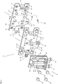
- Fig. 6a shows the two connecting devices 10, 10 'of Fig. 1b , which are connected by means of mounting screws 99 on the one hand to the first sliding door 91 and on the other hand by means of coupling screws 71 each with a drive lever 7, 7 'of a drive device.
- Fig. 6b shows the connecting devices 10, 10 'of Fig. 6a without the sliding door 91 with a section through the mounting plate 1 along the in Fig. 2 shown section line BB. Due to the cut, the connection plate 2 was partially exposed. It can be seen that the first connecting bolts or rivets 41 are passed through the slot openings 24. Furthermore, it is shown that the second connecting screws or rivets 42 are held in receiving openings, for example threaded bores 26. Furthermore, it is shown that the second connecting flange 22 is guided into the window opening 35 in the coupling plate 3. It is further shown that the third adjusting screw 13 (not shown) is rotatable against the stop member 25 by the threaded bore 150 provided in the adjusting flange 15.
- Fig. 6c shows the bottom of the cabinet 9 of Fig. 1a seen from the front with two drives 8A, 8B, which each have two drive lever 7, 7 'and associated connection devices 10, 10 'are each connected to one of the sliding doors 91, 92.
- the connecting devices 10, 10 ' the second and the third adjusting screw 23, 13 are visible, which can be easily operated by means of a suitable tool.
Landscapes
- Engineering & Computer Science (AREA)
- Mechanical Engineering (AREA)
- Civil Engineering (AREA)
- Structural Engineering (AREA)
- Hinges (AREA)
- Securing Of Glass Panes Or The Like (AREA)
- Support Devices For Sliding Doors (AREA)
- Cabinets, Racks, Or The Like Of Rigid Construction (AREA)
Claims (13)
- Dispositif de connexion (10) avec une plaque de montage (1), qui est d'une part destinée à être vissée par des vis de montage (99) à une porte coulissante (91) et d'autre part destinée à être connectée à dispositif d'entraînement (8A), une plaque de connexion (2) étant prévue, qui est arrangé entre la plaque de montage (1) et une plaque d'accouplement (3) du dispositif de connexion (10), ladite plaque d'accouplement (3) étant connectable au dispositif d'entraînement (8A), la plaque de connexion étant déplaçable par des premiers éléments de connexion (41) dans une première direction et peut verrouillé, de manière connecté à la plaque de montage (1), par une première vis d'ajustage (12) dans une position déplacée choisie, et la plaque d'accouplement (3) étant déplaçable par des deuxièmes éléments de connexion (42) dans une deuxième direction et peut verrouillé, de manière connecté à la plaque de montage (1), par une deuxième vis d'ajustage (23) dans une position déplacée choisie, caractérisé en ce que une troisième vis d'ajustage (13) est prévue, qui est tenue dans un trou taraudé (150) d'une bride d'ajustage (15) de la plaque de montage (1) et qui est rotative par rapport à une butée (25), qui est prévue sur la plaque de connexion (2) ou sur la plaque d'accouplement (3) et par laquelle la plaque d'accouplement (3) ou une partie de celle-là peut être tournée par rapport à la plaque de montage (1).
- Dispositif de connexion (10) selon la revendication 1, caractérisé en ce que la plaque de connexion (2) est déplaçable horizontalement par rapport à la plaque de montage (1) et que la plaque d'accouplement (3) est déplaçable verticalement par rapport à la plaque de connexion (2) ou que la plaque de connexion (2) est déplaçable verticalement par rapport à la plaque de montage (1) et que la plaque d'accouplement (3) est déplaçable horizontalement par rapport à la plaque de connexion (2).
- Dispositif de connexion (10) selon la revendication 1 ou 2, caractérisé en ce que les premiers éléments de connexion (41) sont des éléments de bride qui s'imbriquent ou des premiers vis de connexion ou rivets, qui sont tenus dans la plaque de montage (1) dans des premières ouvertures (14) et dans la plaque de connexion (2) dans de premières fentes longitudinales (24).
- Dispositif de connexion (10) selon la revendication 1, 2 ou 3, caractérisé en ce que les deuxièmes éléments de connexion (42) sont des éléments de bride qui s'imbriquent ou des deuxièmes vis de connexion, qui sont tenus dans la plaque de connexion (2) dans des deuxièmes ouvertures (26) et dans la plaque d'accouplement (3) dans de deuxièmes fentes longitudinales (34).
- Dispositif de connexion (10) selon la revendication 3 ou 4, caractérisé en ce que la première et la deuxième fente longitudinale (24, 34) sont orientés le long de la première ou deuxième direction de manière inclinées ou orthogonales l'un par rapport à l'autre.
- Dispositif de connexion (10) selon une des revendications 1 - 5, caractérisé en ce que la plaque de montage (1) présente une bride de montage (11) et la plaque de connexion (2) présente une première bride de connexion (21) et que la bride de montage (11) ou la première bride de connexion (21) présentent un trou taraudé destiné à recevoir la première vis d'ajustage (12) et que la bride de montage (11) ou la première bride de connexion (21) présentent un élément de fixation (111) destiné à tenir de manière rotative la première vis d'ajustage (12).
- Dispositif de connexion (10) selon une des revendications 1 - 6, caractérisé en ce que la plaque de connexion (2) présente une deuxième bride de connexion (22) et que la plaque d'accouplement (3) présente une bride d'accouplement (31) et une ouverture de fenêtre (35), dans laquelle pénètre la deuxième bride de connexion (22), et que la bride d'accouplement (31) ou la deuxième bride de connexion (22) présentent un trou taraudé destiné à recevoir la deuxième vis d'ajustage (23) et que la deuxième bride de connexion (22) ou la bride d'accouplement (31) présentent un élément de fixation (111) destiné à tenir de manière rotative la première vis d'ajustage (12) .
- Dispositif de connexion (10) selon une des revendications 1 - 7, caractérisé en ce que la plaque de montage (1) ou la plaque de connexion (2) ou la plaque d'accouplement (3) présentent au moins un joint (190), autour duquel la plaque de montage (1) ou la plaque d'accouplement (3) ou une partie de celle-là est rotative lors de la manipulation de la vis d'ajustage (13).
- Dispositif de connexion (10) selon la revendication 8, caractérisé en ce que le joint (190) est un joint de flexion, auquel au moins une incision (19) se raccorde.
- Dispositif de connexion (10) selon une des revendications 1 - 9, caractérisé en ce que la deuxième et la troisième vis d'ajustage d (23, 13) sont arrangé du même côté, de préférence sur la face inférieure du dispositif de connexion (10).
- Dispositif de connexion (10) selon une des revendications 1 - 10, caractérisé en ce que la plaque de montage (1), la plaque de connexion (2) et/ou la plaque d'accouplement (3) éventuellement sans la bride d'ajustage (15) et la butée (25) sont formés de manière symétrique et/ou en acier, tôle d'acier ou en zinc moulé sous pression.
- Meuble (9), en particulier une armoire, avec au moins une porte coulissante (91, 92), qui est reliée par au moins un dispositif de connexion (10) selon une des revendications 1 - 11 à un dispositif d'entraînement (8A; 8B) correspondant.
- Meuble (9) selon la revendication 12, caractérisé en ce que le au moins un dispositif de connexion (10) dépasse la porte coulissante (91; 92) en bas ou en haut du meuble (9), tel que au moins la deuxième et/ou la troisième vis d'ajustage (23, 13) en bas ou en haut de la porte coulissante (91; 92) sont accessibles.
Priority Applications (3)
| Application Number | Priority Date | Filing Date | Title |
|---|---|---|---|
| EP15165291.4A EP3088645B1 (fr) | 2015-04-27 | 2015-04-27 | Dispositif de liaison pour une porte coulissante |
| US15/138,395 US10145166B2 (en) | 2015-04-27 | 2016-04-26 | Connecting device for a sliding door |
| JP2016089799A JP6864332B2 (ja) | 2015-04-27 | 2016-04-27 | 摺動ドアのための接続デバイス |
Applications Claiming Priority (1)
| Application Number | Priority Date | Filing Date | Title |
|---|---|---|---|
| EP15165291.4A EP3088645B1 (fr) | 2015-04-27 | 2015-04-27 | Dispositif de liaison pour une porte coulissante |
Publications (2)
| Publication Number | Publication Date |
|---|---|
| EP3088645A1 EP3088645A1 (fr) | 2016-11-02 |
| EP3088645B1 true EP3088645B1 (fr) | 2018-06-27 |
Family
ID=53005511
Family Applications (1)
| Application Number | Title | Priority Date | Filing Date |
|---|---|---|---|
| EP15165291.4A Active EP3088645B1 (fr) | 2015-04-27 | 2015-04-27 | Dispositif de liaison pour une porte coulissante |
Country Status (3)
| Country | Link |
|---|---|
| US (1) | US10145166B2 (fr) |
| EP (1) | EP3088645B1 (fr) |
| JP (1) | JP6864332B2 (fr) |
Families Citing this family (10)
| Publication number | Priority date | Publication date | Assignee | Title |
|---|---|---|---|---|
| PL3204583T3 (pl) * | 2014-10-12 | 2022-08-08 | Bortoluzzi Sistemi S.P.A. | Mebel z mechanizmem przesuwnego skrzydła |
| US9708161B2 (en) * | 2015-08-31 | 2017-07-18 | Elevator Safety Company | Universal adapter assembly for connecting a roller guide to a frame of an elevator car |
| KR101674346B1 (ko) * | 2016-03-31 | 2016-11-08 | 정용일 | 미닫이용 도어의 슬라이딩 장치 |
| AT519904B1 (de) * | 2017-05-11 | 2022-07-15 | Blum Gmbh Julius | Führungsschlitten zur verfahrbaren Lagerung eines Möbelteiles |
| DE102017121844A1 (de) * | 2017-09-20 | 2019-03-21 | Hettich-Heinze Gmbh & Co. Kg | Führungsbeschlag für ein Schiebetürmöbel und Schiebetürmöbel |
| CN108759284B (zh) * | 2018-05-18 | 2021-09-14 | 海尔智家股份有限公司 | 螺钉装配元件、抽屉组件及制冷设备 |
| US10662030B2 (en) * | 2018-06-02 | 2020-05-26 | Elevator Safety Company | Unit or one or more members for an elevator component that allows the elevator component to withstand a seismic event or other significant force generating event |
| CN109907516B (zh) * | 2019-04-09 | 2021-04-13 | 张宝印 | 一种智能家居衣柜 |
| SE544135C2 (en) * | 2020-05-04 | 2022-01-11 | Ikea Supply Ag | Sliding closet door assembly, bypass door assembly, and method for connecting a sliding door |
| KR20240137838A (ko) * | 2023-03-09 | 2024-09-20 | 현대자동차주식회사 | 위치 조정이 용이한 차량의 슬라이드 아웃 타입 도어 어셈블리 및 이의 단차 조정 방법 |
Family Cites Families (12)
| Publication number | Priority date | Publication date | Assignee | Title |
|---|---|---|---|---|
| US1105918A (en) * | 1912-05-23 | 1914-08-04 | W V B Topping | Barn-door hanger part. |
| DE466175C (de) | 1927-08-05 | 1928-10-02 | Julius Wankmueller | Schiebetuer |
| US2940112A (en) * | 1958-02-04 | 1960-06-14 | Lawrence Brothers | Sliding door hanger |
| US6698138B1 (en) * | 2003-04-09 | 2004-03-02 | Heade Technology Co., Ltd. | Adjustable pulley assembly for a suspended door |
| JP4337025B2 (ja) * | 2003-05-07 | 2009-09-30 | スガツネ工業株式会社 | 蝶番 |
| US7770329B2 (en) * | 2005-07-13 | 2010-08-10 | Milgard Manufacturing Incorporated | Door roller system |
| EP2218858B1 (fr) | 2009-02-15 | 2013-10-16 | Hawa Ag | Train de roulement pour un élément de séparation, élément de séparation et dispositif |
| CH702441A1 (de) | 2009-12-18 | 2011-06-30 | Eku Ag | Laufwerksanordnung mit zwei Führungsschienen für eine Schiebetür. |
| US9163445B2 (en) * | 2010-06-24 | 2015-10-20 | Stefan B. Andren | Alignment mechanism |
| SE535000C2 (sv) * | 2010-07-07 | 2012-03-13 | Assa Abloy Ip Ab | Löpvagn för en skjutdörr och metod för byte av hjul på en löpvagn samt användning |
| CH707699B1 (de) * | 2013-03-12 | 2020-11-30 | Hawa Sliding Solutions Ag | Befestigungswinkel für eine Schiebetür und Schrank. |
| US9708161B2 (en) * | 2015-08-31 | 2017-07-18 | Elevator Safety Company | Universal adapter assembly for connecting a roller guide to a frame of an elevator car |
-
2015
- 2015-04-27 EP EP15165291.4A patent/EP3088645B1/fr active Active
-
2016
- 2016-04-26 US US15/138,395 patent/US10145166B2/en active Active
- 2016-04-27 JP JP2016089799A patent/JP6864332B2/ja active Active
Non-Patent Citations (1)
| Title |
|---|
| None * |
Also Published As
| Publication number | Publication date |
|---|---|
| JP6864332B2 (ja) | 2021-04-28 |
| US20160312520A1 (en) | 2016-10-27 |
| EP3088645A1 (fr) | 2016-11-02 |
| JP2016205127A (ja) | 2016-12-08 |
| US10145166B2 (en) | 2018-12-04 |
Similar Documents
| Publication | Publication Date | Title |
|---|---|---|
| EP3088645A1 (fr) | Dispositif de liaison pour une porte coulissante | |
| EP3707331B1 (fr) | Paroi latérale d'un corps de meuble avec ferrure et meuble muni d'une paroi latérale | |
| EP2246509B1 (fr) | Dispositif de déplacement pour éléments de séparation maintenus de manière rotative et élément de mobilier | |
| EP2531070B1 (fr) | Glissière pour tiroir | |
| EP2531065B1 (fr) | Châssis de tiroir | |
| EP2531068B1 (fr) | Dispositif d'accouplement à réglage latéral pour tiroir | |
| EP2851497B1 (fr) | Dispositif de montage réglable pour un élément coulissant et dispositif coulissant | |
| EP3625417B1 (fr) | Bras de commande réglable en longueur | |
| DE102009025890A1 (de) | Vorrichtung zur Befestigung einer Frontblende an einer Seitenzarge eines beweglichen Möbelteils eines Möbels, Schubkasten und Möbel | |
| EP3103948B1 (fr) | Penture pour une porte ou une fenêtre | |
| EP1743128B1 (fr) | Appareil menager comportant un ecran d'affichage pivotant | |
| EP3625415B1 (fr) | Palier de volet équipé d'un accessoire de réglage | |
| EP1653031B1 (fr) | Charnière de porte pliante | |
| EP2774509B1 (fr) | Dispositif d'orientation d'une façade de mobilier mobile | |
| DE202011104559U1 (de) | Vorrichtung mit einer Anbringeinrichtung zur lösbaren Verbindung eines Frontteils einer Schublade mit einer Profilleiste sowie Möbel | |
| EP2949844B1 (fr) | Agencement de bande pour portes, fenêtres ou analogues, doté d'un dispositif de réglage de jeu de joint | |
| DE202009016669U1 (de) | Möbel, Möbelteil und Vorrichtung zur Verbindung eines Frontbauteils eines Möbelteils | |
| EP2256443B1 (fr) | Système de porte pour un appareil de réfrigération et/ou de congélation, appareil de réfrigération et/ou de congélation et procédé destiné au montage d'un système de porte | |
| EP2208843B1 (fr) | Charnière pour une porte | |
| EP2233039B1 (fr) | Guidage pour tiroirs | |
| EP1454026B1 (fr) | Plaque de montage pour la fixation reglable de charnieres de meuble sur le corps de meubles | |
| EP3704337B1 (fr) | Pièce de bande | |
| DE2851658A1 (de) | Oberlichtoeffner o.dgl. | |
| EP3336290A1 (fr) | Fermeture pour une gorge à armature à contre-dépouille d'une ferrures du type à tige d'entraînement | |
| EP3379013A1 (fr) | Dispositif de guidage réglable pour un élément coulissant |
Legal Events
| Date | Code | Title | Description |
|---|---|---|---|
| PUAI | Public reference made under article 153(3) epc to a published international application that has entered the european phase |
Free format text: ORIGINAL CODE: 0009012 |
|
| AK | Designated contracting states |
Kind code of ref document: A1 Designated state(s): AL AT BE BG CH CY CZ DE DK EE ES FI FR GB GR HR HU IE IS IT LI LT LU LV MC MK MT NL NO PL PT RO RS SE SI SK SM TR |
|
| AX | Request for extension of the european patent |
Extension state: BA ME |
|
| 17P | Request for examination filed |
Effective date: 20170502 |
|
| RBV | Designated contracting states (corrected) |
Designated state(s): AL AT BE BG CH CY CZ DE DK EE ES FI FR GB GR HR HU IE IS IT LI LT LU LV MC MK MT NL NO PL PT RO RS SE SI SK SM TR |
|
| RAP1 | Party data changed (applicant data changed or rights of an application transferred) |
Owner name: HAWA SLIDING SOLUTIONS AG |
|
| STAA | Information on the status of an ep patent application or granted ep patent |
Free format text: STATUS: REQUEST FOR EXAMINATION WAS MADE |
|
| GRAP | Despatch of communication of intention to grant a patent |
Free format text: ORIGINAL CODE: EPIDOSNIGR1 |
|
| STAA | Information on the status of an ep patent application or granted ep patent |
Free format text: STATUS: GRANT OF PATENT IS INTENDED |
|
| INTG | Intention to grant announced |
Effective date: 20180124 |
|
| GRAS | Grant fee paid |
Free format text: ORIGINAL CODE: EPIDOSNIGR3 |
|
| GRAA | (expected) grant |
Free format text: ORIGINAL CODE: 0009210 |
|
| STAA | Information on the status of an ep patent application or granted ep patent |
Free format text: STATUS: THE PATENT HAS BEEN GRANTED |
|
| AK | Designated contracting states |
Kind code of ref document: B1 Designated state(s): AL AT BE BG CH CY CZ DE DK EE ES FI FR GB GR HR HU IE IS IT LI LT LU LV MC MK MT NL NO PL PT RO RS SE SI SK SM TR |
|
| REG | Reference to a national code |
Ref country code: GB Ref legal event code: FG4D Free format text: NOT ENGLISH |
|
| REG | Reference to a national code |
Ref country code: AT Ref legal event code: REF Ref document number: 1012510 Country of ref document: AT Kind code of ref document: T Effective date: 20180715 |
|
| REG | Reference to a national code |
Ref country code: DE Ref legal event code: R096 Ref document number: 502015004798 Country of ref document: DE |
|
| REG | Reference to a national code |
Ref country code: IE Ref legal event code: FG4D Free format text: LANGUAGE OF EP DOCUMENT: GERMAN |
|
| REG | Reference to a national code |
Ref country code: CH Ref legal event code: NV Representative=s name: PETER RUTZ C/O RUTZ AND PARTNER, CH |
|
| PG25 | Lapsed in a contracting state [announced via postgrant information from national office to epo] |
Ref country code: NO Free format text: LAPSE BECAUSE OF FAILURE TO SUBMIT A TRANSLATION OF THE DESCRIPTION OR TO PAY THE FEE WITHIN THE PRESCRIBED TIME-LIMIT Effective date: 20180927 Ref country code: FI Free format text: LAPSE BECAUSE OF FAILURE TO SUBMIT A TRANSLATION OF THE DESCRIPTION OR TO PAY THE FEE WITHIN THE PRESCRIBED TIME-LIMIT Effective date: 20180627 Ref country code: LT Free format text: LAPSE BECAUSE OF FAILURE TO SUBMIT A TRANSLATION OF THE DESCRIPTION OR TO PAY THE FEE WITHIN THE PRESCRIBED TIME-LIMIT Effective date: 20180627 Ref country code: BG Free format text: LAPSE BECAUSE OF FAILURE TO SUBMIT A TRANSLATION OF THE DESCRIPTION OR TO PAY THE FEE WITHIN THE PRESCRIBED TIME-LIMIT Effective date: 20180927 Ref country code: SE Free format text: LAPSE BECAUSE OF FAILURE TO SUBMIT A TRANSLATION OF THE DESCRIPTION OR TO PAY THE FEE WITHIN THE PRESCRIBED TIME-LIMIT Effective date: 20180627 |
|
| REG | Reference to a national code |
Ref country code: NL Ref legal event code: MP Effective date: 20180627 |
|
| REG | Reference to a national code |
Ref country code: LT Ref legal event code: MG4D |
|
| PG25 | Lapsed in a contracting state [announced via postgrant information from national office to epo] |
Ref country code: LV Free format text: LAPSE BECAUSE OF FAILURE TO SUBMIT A TRANSLATION OF THE DESCRIPTION OR TO PAY THE FEE WITHIN THE PRESCRIBED TIME-LIMIT Effective date: 20180627 Ref country code: HR Free format text: LAPSE BECAUSE OF FAILURE TO SUBMIT A TRANSLATION OF THE DESCRIPTION OR TO PAY THE FEE WITHIN THE PRESCRIBED TIME-LIMIT Effective date: 20180627 Ref country code: GR Free format text: LAPSE BECAUSE OF FAILURE TO SUBMIT A TRANSLATION OF THE DESCRIPTION OR TO PAY THE FEE WITHIN THE PRESCRIBED TIME-LIMIT Effective date: 20180928 Ref country code: RS Free format text: LAPSE BECAUSE OF FAILURE TO SUBMIT A TRANSLATION OF THE DESCRIPTION OR TO PAY THE FEE WITHIN THE PRESCRIBED TIME-LIMIT Effective date: 20180627 |
|
| PG25 | Lapsed in a contracting state [announced via postgrant information from national office to epo] |
Ref country code: NL Free format text: LAPSE BECAUSE OF FAILURE TO SUBMIT A TRANSLATION OF THE DESCRIPTION OR TO PAY THE FEE WITHIN THE PRESCRIBED TIME-LIMIT Effective date: 20180627 |
|
| PG25 | Lapsed in a contracting state [announced via postgrant information from national office to epo] |
Ref country code: IS Free format text: LAPSE BECAUSE OF FAILURE TO SUBMIT A TRANSLATION OF THE DESCRIPTION OR TO PAY THE FEE WITHIN THE PRESCRIBED TIME-LIMIT Effective date: 20181027 Ref country code: PL Free format text: LAPSE BECAUSE OF FAILURE TO SUBMIT A TRANSLATION OF THE DESCRIPTION OR TO PAY THE FEE WITHIN THE PRESCRIBED TIME-LIMIT Effective date: 20180627 Ref country code: EE Free format text: LAPSE BECAUSE OF FAILURE TO SUBMIT A TRANSLATION OF THE DESCRIPTION OR TO PAY THE FEE WITHIN THE PRESCRIBED TIME-LIMIT Effective date: 20180627 Ref country code: CZ Free format text: LAPSE BECAUSE OF FAILURE TO SUBMIT A TRANSLATION OF THE DESCRIPTION OR TO PAY THE FEE WITHIN THE PRESCRIBED TIME-LIMIT Effective date: 20180627 Ref country code: RO Free format text: LAPSE BECAUSE OF FAILURE TO SUBMIT A TRANSLATION OF THE DESCRIPTION OR TO PAY THE FEE WITHIN THE PRESCRIBED TIME-LIMIT Effective date: 20180627 Ref country code: SK Free format text: LAPSE BECAUSE OF FAILURE TO SUBMIT A TRANSLATION OF THE DESCRIPTION OR TO PAY THE FEE WITHIN THE PRESCRIBED TIME-LIMIT Effective date: 20180627 |
|
| PG25 | Lapsed in a contracting state [announced via postgrant information from national office to epo] |
Ref country code: ES Free format text: LAPSE BECAUSE OF FAILURE TO SUBMIT A TRANSLATION OF THE DESCRIPTION OR TO PAY THE FEE WITHIN THE PRESCRIBED TIME-LIMIT Effective date: 20180627 Ref country code: SM Free format text: LAPSE BECAUSE OF FAILURE TO SUBMIT A TRANSLATION OF THE DESCRIPTION OR TO PAY THE FEE WITHIN THE PRESCRIBED TIME-LIMIT Effective date: 20180627 |
|
| REG | Reference to a national code |
Ref country code: DE Ref legal event code: R097 Ref document number: 502015004798 Country of ref document: DE |
|
| PLBE | No opposition filed within time limit |
Free format text: ORIGINAL CODE: 0009261 |
|
| STAA | Information on the status of an ep patent application or granted ep patent |
Free format text: STATUS: NO OPPOSITION FILED WITHIN TIME LIMIT |
|
| PG25 | Lapsed in a contracting state [announced via postgrant information from national office to epo] |
Ref country code: DK Free format text: LAPSE BECAUSE OF FAILURE TO SUBMIT A TRANSLATION OF THE DESCRIPTION OR TO PAY THE FEE WITHIN THE PRESCRIBED TIME-LIMIT Effective date: 20180627 |
|
| 26N | No opposition filed |
Effective date: 20190328 |
|
| PG25 | Lapsed in a contracting state [announced via postgrant information from national office to epo] |
Ref country code: SI Free format text: LAPSE BECAUSE OF FAILURE TO SUBMIT A TRANSLATION OF THE DESCRIPTION OR TO PAY THE FEE WITHIN THE PRESCRIBED TIME-LIMIT Effective date: 20180627 |
|
| PG25 | Lapsed in a contracting state [announced via postgrant information from national office to epo] |
Ref country code: AL Free format text: LAPSE BECAUSE OF FAILURE TO SUBMIT A TRANSLATION OF THE DESCRIPTION OR TO PAY THE FEE WITHIN THE PRESCRIBED TIME-LIMIT Effective date: 20180627 |
|
| REG | Reference to a national code |
Ref country code: BE Ref legal event code: MM Effective date: 20190430 |
|
| GBPC | Gb: european patent ceased through non-payment of renewal fee |
Effective date: 20190427 |
|
| PG25 | Lapsed in a contracting state [announced via postgrant information from national office to epo] |
Ref country code: MC Free format text: LAPSE BECAUSE OF FAILURE TO SUBMIT A TRANSLATION OF THE DESCRIPTION OR TO PAY THE FEE WITHIN THE PRESCRIBED TIME-LIMIT Effective date: 20180627 Ref country code: LU Free format text: LAPSE BECAUSE OF NON-PAYMENT OF DUE FEES Effective date: 20190427 |
|
| PG25 | Lapsed in a contracting state [announced via postgrant information from national office to epo] |
Ref country code: GB Free format text: LAPSE BECAUSE OF NON-PAYMENT OF DUE FEES Effective date: 20190427 |
|
| PG25 | Lapsed in a contracting state [announced via postgrant information from national office to epo] |
Ref country code: FR Free format text: LAPSE BECAUSE OF NON-PAYMENT OF DUE FEES Effective date: 20190430 Ref country code: BE Free format text: LAPSE BECAUSE OF NON-PAYMENT OF DUE FEES Effective date: 20190430 |
|
| PG25 | Lapsed in a contracting state [announced via postgrant information from national office to epo] |
Ref country code: TR Free format text: LAPSE BECAUSE OF FAILURE TO SUBMIT A TRANSLATION OF THE DESCRIPTION OR TO PAY THE FEE WITHIN THE PRESCRIBED TIME-LIMIT Effective date: 20180627 |
|
| PG25 | Lapsed in a contracting state [announced via postgrant information from national office to epo] |
Ref country code: IE Free format text: LAPSE BECAUSE OF NON-PAYMENT OF DUE FEES Effective date: 20190427 |
|
| PG25 | Lapsed in a contracting state [announced via postgrant information from national office to epo] |
Ref country code: PT Free format text: LAPSE BECAUSE OF FAILURE TO SUBMIT A TRANSLATION OF THE DESCRIPTION OR TO PAY THE FEE WITHIN THE PRESCRIBED TIME-LIMIT Effective date: 20181029 |
|
| PG25 | Lapsed in a contracting state [announced via postgrant information from national office to epo] |
Ref country code: CY Free format text: LAPSE BECAUSE OF FAILURE TO SUBMIT A TRANSLATION OF THE DESCRIPTION OR TO PAY THE FEE WITHIN THE PRESCRIBED TIME-LIMIT Effective date: 20180627 |
|
| REG | Reference to a national code |
Ref country code: AT Ref legal event code: MM01 Ref document number: 1012510 Country of ref document: AT Kind code of ref document: T Effective date: 20200427 |
|
| PG25 | Lapsed in a contracting state [announced via postgrant information from national office to epo] |
Ref country code: HU Free format text: LAPSE BECAUSE OF FAILURE TO SUBMIT A TRANSLATION OF THE DESCRIPTION OR TO PAY THE FEE WITHIN THE PRESCRIBED TIME-LIMIT; INVALID AB INITIO Effective date: 20150427 Ref country code: MT Free format text: LAPSE BECAUSE OF FAILURE TO SUBMIT A TRANSLATION OF THE DESCRIPTION OR TO PAY THE FEE WITHIN THE PRESCRIBED TIME-LIMIT Effective date: 20180627 |
|
| PG25 | Lapsed in a contracting state [announced via postgrant information from national office to epo] |
Ref country code: AT Free format text: LAPSE BECAUSE OF NON-PAYMENT OF DUE FEES Effective date: 20200427 |
|
| PG25 | Lapsed in a contracting state [announced via postgrant information from national office to epo] |
Ref country code: MK Free format text: LAPSE BECAUSE OF FAILURE TO SUBMIT A TRANSLATION OF THE DESCRIPTION OR TO PAY THE FEE WITHIN THE PRESCRIBED TIME-LIMIT Effective date: 20180627 |
|
| P01 | Opt-out of the competence of the unified patent court (upc) registered |
Effective date: 20230529 |
|
| PGFP | Annual fee paid to national office [announced via postgrant information from national office to epo] |
Ref country code: DE Payment date: 20250422 Year of fee payment: 11 |
|
| PGFP | Annual fee paid to national office [announced via postgrant information from national office to epo] |
Ref country code: IT Payment date: 20250424 Year of fee payment: 11 |
|
| PGFP | Annual fee paid to national office [announced via postgrant information from national office to epo] |
Ref country code: CH Payment date: 20250501 Year of fee payment: 11 |
|
| REG | Reference to a national code |
Ref country code: CH Ref legal event code: U11 Free format text: ST27 STATUS EVENT CODE: U-0-0-U10-U11 (AS PROVIDED BY THE NATIONAL OFFICE) Effective date: 20260501 |