EP3088676B1 - Dispositif d'amortissement de moteur à turbine à gaz - Google Patents
Dispositif d'amortissement de moteur à turbine à gaz Download PDFInfo
- Publication number
- EP3088676B1 EP3088676B1 EP16164198.0A EP16164198A EP3088676B1 EP 3088676 B1 EP3088676 B1 EP 3088676B1 EP 16164198 A EP16164198 A EP 16164198A EP 3088676 B1 EP3088676 B1 EP 3088676B1
- Authority
- EP
- European Patent Office
- Prior art keywords
- damping device
- extension
- recessed area
- gas turbine
- blade
- Prior art date
- Legal status (The legal status is an assumption and is not a legal conclusion. Google has not performed a legal analysis and makes no representation as to the accuracy of the status listed.)
- Active
Links
Images



Classifications
-
- F—MECHANICAL ENGINEERING; LIGHTING; HEATING; WEAPONS; BLASTING
- F01—MACHINES OR ENGINES IN GENERAL; ENGINE PLANTS IN GENERAL; STEAM ENGINES
- F01D—NON-POSITIVE DISPLACEMENT MACHINES OR ENGINES, e.g. STEAM TURBINES
- F01D5/00—Blades; Blade-carrying members; Heating, heat-insulating, cooling or antivibration means on the blades or the members
- F01D5/12—Blades
- F01D5/22—Blade-to-blade connections, e.g. for damping vibrations
-
- F—MECHANICAL ENGINEERING; LIGHTING; HEATING; WEAPONS; BLASTING
- F01—MACHINES OR ENGINES IN GENERAL; ENGINE PLANTS IN GENERAL; STEAM ENGINES
- F01D—NON-POSITIVE DISPLACEMENT MACHINES OR ENGINES, e.g. STEAM TURBINES
- F01D11/00—Preventing or minimising internal leakage of working-fluid, e.g. between stages
- F01D11/005—Sealing means between non relatively rotating elements
- F01D11/006—Sealing the gap between rotor blades or blades and rotor
-
- F—MECHANICAL ENGINEERING; LIGHTING; HEATING; WEAPONS; BLASTING
- F01—MACHINES OR ENGINES IN GENERAL; ENGINE PLANTS IN GENERAL; STEAM ENGINES
- F01D—NON-POSITIVE DISPLACEMENT MACHINES OR ENGINES, e.g. STEAM TURBINES
- F01D25/00—Component parts, details, or accessories, not provided for in, or of interest apart from, other groups
- F01D25/04—Antivibration arrangements
- F01D25/06—Antivibration arrangements for preventing blade vibration
-
- F—MECHANICAL ENGINEERING; LIGHTING; HEATING; WEAPONS; BLASTING
- F01—MACHINES OR ENGINES IN GENERAL; ENGINE PLANTS IN GENERAL; STEAM ENGINES
- F01D—NON-POSITIVE DISPLACEMENT MACHINES OR ENGINES, e.g. STEAM TURBINES
- F01D5/00—Blades; Blade-carrying members; Heating, heat-insulating, cooling or antivibration means on the blades or the members
- F01D5/30—Fixing blades to rotors; Blade roots ; Blade spacers
- F01D5/3007—Fixing blades to rotors; Blade roots ; Blade spacers of axial insertion type
-
- F—MECHANICAL ENGINEERING; LIGHTING; HEATING; WEAPONS; BLASTING
- F05—INDEXING SCHEMES RELATING TO ENGINES OR PUMPS IN VARIOUS SUBCLASSES OF CLASSES F01-F04
- F05D—INDEXING SCHEME FOR ASPECTS RELATING TO NON-POSITIVE-DISPLACEMENT MACHINES OR ENGINES, GAS-TURBINES OR JET-PROPULSION PLANTS
- F05D2220/00—Application
- F05D2220/30—Application in turbines
- F05D2220/32—Application in turbines in gas turbines
-
- F—MECHANICAL ENGINEERING; LIGHTING; HEATING; WEAPONS; BLASTING
- F05—INDEXING SCHEMES RELATING TO ENGINES OR PUMPS IN VARIOUS SUBCLASSES OF CLASSES F01-F04
- F05D—INDEXING SCHEME FOR ASPECTS RELATING TO NON-POSITIVE-DISPLACEMENT MACHINES OR ENGINES, GAS-TURBINES OR JET-PROPULSION PLANTS
- F05D2240/00—Components
- F05D2240/80—Platforms for stationary or moving blades
Definitions
- Component assemblies of gas turbine engines can vibrate during operation. Damping devices can be used to damp the vibrations. Damping the vibrations can prevent the vibrations from accelerating fatigue.
- the damping devices are positioned between circumferentially adjacent blades within a gas turbine engine. Interfaces between the circumferentially adjacent blades are typically sealed. The damping devices are often near these interfaces.
- US 2012/0121424 A1 discloses a damper pin for a turbine bucket including an elongated main body portion having a first substantially uniform cross-sectional shape and axially-aligned, leading and trailing end portions having a second relatively smaller cross-sectional shape at opposite ends of the main body portion.
- a seal element is provided on one or both of the opposite leading and trailing end portions projecting radially outwardly beyond the main body portion.
- US 2014/0112786 A1 discloses a damper body which extends between an axial first end, an opposing axial second end, a first lateral side, and an opposing second lateral side.
- the invention provides a gas turbine engine assembly as claimed in claim 1.
- the gas turbine engine component is a blade and the extension is first extension from a root of a first blade, and the first recessed area is further configured to engage a second extension from a root of a second blade when the second side engages the seal.
- radially inward movement of the damping device is limited exclusively by the first extension and the second extension.
- the damping device is configured to be positioned circumferentially between a first blade and a second blade.
- the first blade and the second blade are constituents of a turbine blade array.
- the damping device is a cast component.
- the components are blades and the first extension extends from a root of one of the blades, and the second extension extends from a root of the second one of the blades.
- the first side includes a first recessed area that receives the one of the seals
- the second side includes a second recessed area that receives both the first extension and the second extension.
- the plurality of components are turbine blade assemblies.
- the seals are blade platform seals.
- the seals contact platforms of the components to limit movement of the damping device away from the axis.
- each of the damping device toward the axis is limited, exclusively, by the first extension and the second extension when the damping device is in an installed position.
- a method of damping and sealing a component array as claimed in claim 10 is also provided.
- the damping device receives the extension within a recess to engage the extension.
- the damping device receives the seal within a recess to engage the seal.
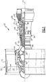
- FIG. 1 schematically illustrates a gas turbine engine 20.
- the gas turbine engine 20 is disclosed herein as a two-spool turbofan that generally incorporates a fan section 22, a compressor section 24, a combustor section 26 and a turbine section 28.
- the fan section 22 drives air along a bypass flow path B in a bypass duct defined within a nacelle 15, while the compressor section 24 drives air along a core flow path C for compression and communication into the combustor section 26 then expansion through the turbine section 28.
- the examples herein are not limited to use with two-spool turbofans and may be applied to other types of turbomachinery, including direct drive engine architectures, three-spool engine architectures, and ground-based turbines.
- the engine 20 generally includes a low speed spool 30 and a high speed spool 32 mounted for rotation about an engine central longitudinal axis A relative to an engine static structure 36 via several bearing systems 38. It should be understood that various bearing systems 38 at various locations may alternatively or additionally be provided, and the location of bearing systems 38 may be varied as appropriate to the application.
- the low speed spool 30 generally includes an inner shaft 40 that interconnects a fan 42, a first (or low) pressure compressor 44 and a first (or low) pressure turbine 46.
- the inner shaft 40 is connected to the fan 42 through a speed change mechanism, which in exemplary gas turbine engine 20 is illustrated as a geared architecture 48, to drive the fan 42 at a lower speed than the low speed spool 30.
- the high speed spool 32 includes an outer shaft 50 that interconnects a second (or high) pressure compressor 52 and a second (or high) pressure turbine 54.
- a combustor 56 is arranged between the high pressure compressor 52 and the high pressure turbine 54.
- a mid-turbine frame 57 of the engine static structure 36 is arranged generally between the high pressure turbine 54 and the low pressure turbine 46.
- the mid-turbine frame 57 further supports the bearing systems 38 in the turbine section 28.
- the inner shaft 40 and the outer shaft 50 are concentric and rotate via bearing systems 38 about the engine central longitudinal axis A, which is collinear with their longitudinal axes.
- the core airflow is compressed by the low pressure compressor 44 then the high pressure compressor 52, mixed and burned with fuel in the combustor 56, then expanded over the high pressure turbine 54 and low pressure turbine 46.
- the mid-turbine frame 57 includes airfoils 59 which are in the core airflow path C.
- the turbines 46, 54 rotationally drive the respective low speed spool 30 and high speed spool 32 in response to the expansion.
- gear system 48 may be located aft of combustor section 26 or even aft of turbine section 28, and fan section 22 may be positioned forward or aft of the location of gear system 48.
- the engine 20 in one example is a high-bypass geared aircraft engine.
- the engine 20 bypass ratio is greater than about six (6:1), with an example embodiment being greater than about ten (10:1)
- the geared architecture 48 is an epicyclic gear train, such as a planetary gear system or other gear system, with a gear reduction ratio of greater than about 2.3 (2.3:1)
- the low pressure turbine 46 has a pressure ratio that is greater than about five (5:1).
- the engine 20 bypass ratio is greater than about ten (10:1)
- the fan diameter is significantly larger than that of the low pressure compressor 44
- the low pressure turbine 46 has a pressure ratio that is greater than about five (5:1).
- Low pressure turbine 46 pressure ratio is pressure measured prior to inlet of low pressure turbine 46 as related to the pressure at the outlet of the low pressure turbine 46 prior to an exhaust nozzle.
- the geared architecture 48 may be an epicycle gear train, such as a planetary gear system or other gear system, with a gear reduction ratio of greater than about 2.3 (2.3:1). It should be understood, however, that the above parameters are only exemplary of one embodiment of a geared architecture engine and that the present invention is applicable to other gas turbine engines, including direct drive turbofans.
- the fan section 22 of the engine 20 is designed for a particular flight condition -- typically cruise at about 0.8 Mach and about 35,000 feet (10,668 m).
- the flight condition of 0.8 Mach and 35,000 ft (10,668 m), with the engine at its best fuel consumption - also known as "bucket cruise Thrust Specific Fuel Consumption ('TSFC')" - is the industry standard parameter of lbm of fuel being burned divided by lbf of thrust the engine produces at that minimum point.
- "Low fan pressure ratio” is the pressure ratio across the fan blade alone, without a Fan Exit Guide Vane (“FEGV”) system.
- the low fan pressure ratio as disclosed herein according to one non-limiting embodiment is less than about 1.45.
- "Low corrected fan tip speed” is the actual fan tip speed in ft/sec divided by an industry standard temperature correction of [(Tram °R) / (518.7 °R)] 0.5 .
- the "Low corrected fan tip speed” as disclosed herein according to one non-limiting embodiment is less than about 1150 ft / second (350.5 m/s).
- another example gas turbine engine 60 includes an augmentor section 62.
- the engine 60 further includes a fan section 64, a compression section 66, a combustor section 68, and a turbine section 70.
- the engine 60 includes a core flow path C, a first bypass flow path B 1 , and a second bypass flow path B 2 .
- the engine 60 is disposed about an axis A' and operates in a similar fashion to the engine 20 of Figure 1 .
- the engine 20 and the engine 60 both include multiple arrays of components such as vanes and blades.
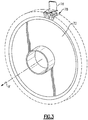
- the turbine section 70 of the engine 60 includes a turbine rotor 72.
- the rotor 72 includes a plurality of slots 78 distributed annularly about the axis A'.
- Figure 3 shows, for clarity, one blade 76 within one of the slots 78. In operation, the rotor 72 would include other blades associated with the other slots 78 of the rotor 72.
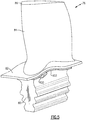
- the example blade 76 includes a root 80, a platform 82, and an airfoil 84 extending from the platform 82 to a tip 86.
- the root 80 includes dovetail or fir-tree features to engage corresponding features of the respective slot 78 within the rotor 72.
- the root 80 is slidably received within the slot 78.
- the example blade 76 includes an extension 90 extending circumferentially from the root 80 at a position radially outside an outer perimeter of the rotor 72. Another extension (not shown) extends circumferentially from an opposite side of the root 80. The other extension is at the same axial location. In some examples, the other extension directly opposes extension 90.
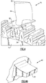
- the extension 90 is a post in this example that tapers from the root 80 to a face 92 ( Figure 4A ).
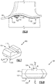
- the extension 90 engages a damping device 100, which holds a seal 102.
- the extension 90 supports the damping device 100 when engaging the damping device 100.
- the seal 102 is a blade platform seal in this example.
- the damping device 100 is positioned circumferentially between the blade 76 and a circumferentially adjacent blade 76a.
- the damping device 100 absorbs vibrational energy from the blade 76 and the circumferentially adjacent blade assembly by engaging in frictional sliding between adjacent blades. Absorbing the vibrational energy can inhibit fatigue.
- the damping device 100 can be positioned axially at a point of the blade 76 found to have the highest level of displacement during operation. Placement at the point of highest vibratory displacement can result in more effective damping.
- the location of maximum displacement during vibration can be at the aft end, the forward end, or somewhere in between depending on the vibratory mode shape.
- the example damping device 100 includes a first side 104 and a second side 108 facing away from the first side 104.
- the first side 104 can face radially inward or radially outward.
- the first side 104 includes a first recessed area 112.
- the second side 108 includes a second recessed area 116.
- a cross-sectional profile of the first recessed area 112 mimics the cross-sectional profile of the second recessed area 116.
- the first recessed area 112 is substantially identical to the second recessed area 116.
- the first recessed area 112 extends longitudinally in a direction D 1 .
- the second recessed area 116 extends longitudinally in a second direction D 2 .
- the direction D 1 is transverse to the direction D 2 .
- the direction D 1 is offset from 65 to 80 degrees from the direction D 2 .
- the direction D 1 is substantially perpendicular to the direction D 2 .
- Damping device 100 includes a first portion 120 and a second portion 121.
- the portions 120 and 121 have the same geometry.
- the damping device 100 presents substantially the same surfaces when in a first position and when in a second position that is rotated 180 degrees about axis D a from the first position.
- the damping device 100 presents substantially the same surfaces when in a third position and when in a fourth position that is rotated 180 degrees about an axis that stretches from one corner C 1 to an opposite corner C 2 . These two rotational transformations create four unique orientations in which the damping device is identical to itself.
- the corners C 1 and C 2 are angled at less than ninety degrees in this example. In another example, the corners C 1 and C 2 are ninety degrees such that the profile of the damping device 100 is square.
- the second recessed area 116 receives the extension 90 when the damping device 100 is installed.
- the first recessed area 112 receives a seal 102.
- first recessed area 112 could receive the extension 90 and the second recessed area 116 could receive the seal 102.
- the damping device 100 can also be rotated 180 degrees about the damping device axis D a and still be in a position appropriate for installation.
- the damping device 100 can be installed so that the first side 104 is facing radially outward or radially inward.
- the seal 102 is supported by the damping device 100.
- the seal 102 includes a leading portion 134 upstream from the damping device 100 and a trailing portion 138 downstream from the damping device 100 ( Figure 6 ).
- the leading portion 134 and the trailing portion 138 are circumferentially enlarged relative to a width W of the first recessed area 112 ( Figure 8 ). Circumferentially enlarging the seal 102 at these locations ensures that the seal 102 will maintain its axial position within the first recessed area 112.
- the circumferential enlarged areas limit axial movement of the seal 102 relative to the damping device 100 when the seal 102 is within the first recessed area 112 or the second recessed area 116.
- the circumferential width of the seal 102 is consistent along the entire axial length of the seal 102.
- the platform 82 interfaces with a platform 82a of the blade 76a at an interface I ( Figure 10 ).
- interface I Figure 10
- circumferential forces due to the rotating rotor 72 force the seal 102 radially outward against the platform 82, which seals the interface I.
- the seal 102 moves against the undersides of the platforms 82 and 82a to seal the interface I.
- the first recessed area 112 is perpendicular to the engine axis A', and the second recessed area 116 is parallel to the interface I.
- the example seal 102 is manufactured from sheet metal or another metallic material.
- the seal 102 may be from .008" - .025" (0.02 - 0.06 cm) thick in some examples.
- radially inward movement of the damping device 100 is limited, exclusively, by the extension 90 and an extension 90a from a root 80a of the blade 76a ( Figure 11 ). Notably, only two extensions 90 and 90a are required to support the damping device 100.
- the example damping device 100 is a cast cobalt alloy.
- the damping device 100 could be nickel.
- the damping device 100 could also be manufactured by an additive manufacturing process in another example.
- the example damping device 100 is described in connection with a blade from the turbine section 70 of the engine 60.
- the example damping device 100 could be used in connection with blades from other areas of the engine 60 or the engine 20, such as the compression sections 24 and 66.
- damping device that can be installed in multiple positions.
- the damping device can accommodate a seal in a first position.
- the damping device can be flipped and rotated ninety degrees to accommodate the same seal in a second position.
- the damping device can also be rotated 180 degrees from an installation position to another installation position.
- the damping device has, in these examples, four potential installation positions, which can reduce potential for installation errors associated with installing the damping device.
Landscapes
- Engineering & Computer Science (AREA)
- Mechanical Engineering (AREA)
- General Engineering & Computer Science (AREA)
- Turbine Rotor Nozzle Sealing (AREA)
Claims (12)
- Ensemble de moteur à turbine à gaz, comprenant :une pluralité de composants (76, 76a) répartis de manière circonférentielle autour d'un axe (A') ;une pluralité de joints (102) ; etun dispositif d'amortissement (100) ayant un premier côté (104) et un second côté (108) opposé au premier côté (104),le premier côté (104) comprend une première zone évidée (112) en prise avec l'un des joints (102), le second côté (108) comprend une seconde zone évidée (116) en prise avec une première extension (90) depuis un premier des composants (76) et en prise en outre avec une seconde extension (90a) depuis un second des composants (76a),caractérisé en ce que la première zone évidée (112) s'étend longitudinalement dans une première direction (D1) et la seconde zone évidée (116) s'étend longitudinalement dans une seconde direction (D2) perpendiculaire à la première direction (D1),dans lequel la première zone évidée (112) a un profil en coupe qui imite un profil en coupe de la seconde zone évidée (116),dans lequel le dispositif d'amortissement (100) est réorientable de sorte que la première zone évidée (112) vient en prise avec les première et seconde extensions (90, 90a), et la seconde zone évidée (116) vient en prise avec l'un des joints (102).
- Ensemble de turbine à gaz selon la revendication 1, dans lequel les composants (76, 76a) sont des aubes et la première extension (90) s'étend depuis un pied (80) de l'une des aubes (76), et la seconde extension (90a) s'étend d'un pied (80a) de la seconde des aubes (76a).
- Ensemble de moteur à turbine à gaz selon la revendication 2, dans lequel un mouvement radialement vers l'intérieur du dispositif d'amortissement (100) est limité exclusivement par la première extension (90) et la seconde extension (90a).
- Ensemble de moteur à turbine à gaz selon une quelconque revendication précédente, dans lequel le dispositif d'amortissement (100) est configuré pour être positionné de manière circonférentielle entre une première aube (76) et une seconde aube (76a).
- Ensemble de moteur à turbine à gaz selon la revendication 4, dans lequel la première aube (76) et la seconde aube (76a) sont des constituants d'un réseau d'aubes de turbine.
- Ensemble de moteur à turbine à gaz selon une quelconque revendication précédente, dans lequel le dispositif d'amortissement (100) est un composant coulé.
- Ensemble de turbine à gaz selon une quelconque revendication précédente, dans lequel la pluralité de composants (76, 76a) sont des ensembles d'aubes de turbine.
- Ensemble de turbine à gaz selon une quelconque revendication précédente, dans lequel les joints (102) :sont des joints de plate-forme d'aube ; et/ouentrent en contact avec les plates-formes (82, 82a) des composants (76, 76a) pour limiter le mouvement du dispositif d'amortissement (100) à l'opposé de l'axe (A').
- Ensemble de turbine à gaz selon une quelconque revendication précédente, dans lequel le mouvement du dispositif d'amortissement (100) vers l'axe (A') est limité exclusivement par la première extension (90) et la seconde extension (90a) lorsque le dispositif d'amortissement (100) est dans une position installée.
- Procédé d'amortissement et de scellement d'un réseau de composants d'un ensemble de turbine à gaz selon une quelconque revendication précédente, comprenant :l'utilisation d'une première zone évidée (112) dans un premier côté (104) d'un dispositif d'amortissement (100) pour venir en prise avec une extension (90) depuis un composant (76) et d'une seconde zone évidée (116) dans un second côté (108) du dispositif d'amortissement (100) pour venir en prise avec un joint (102),caractérisé par le basculement et la rotation du joint (102) ; etl'utilisation de la première zone évidée (112) du dispositif d'amortissement (100) pour venir en prise avec le joint (102) et de la seconde zone évidée (116) du dispositif d'amortissement (100) pour venir en prise avec l'extension (90) .
- Procédé selon la revendication 10, comprenant en outre la limitation du mouvement radialement vers l'extérieur du dispositif d'amortissement (100) en utilisant le joint (102), et la limitation du mouvement radialement vers l'intérieur du dispositif d'amortissement (100) en utilisant l'extension (90) .
- Procédé selon la revendication 10 ou 11, dans lequel le dispositif d'amortissement (100) :
reçoit l'extension (90) à l'intérieur de l'évidement (112, 116) pour venir en prise avec l'extension (90) ; et/ou reçoit le joint (102) à l'intérieur de l'évidement (112, 116) pour venir en prise avec le joint (102).
Applications Claiming Priority (1)
| Application Number | Priority Date | Filing Date | Title |
|---|---|---|---|
| US14/680,139 US9920637B2 (en) | 2015-04-07 | 2015-04-07 | Gas turbine engine damping device |
Publications (2)
| Publication Number | Publication Date |
|---|---|
| EP3088676A1 EP3088676A1 (fr) | 2016-11-02 |
| EP3088676B1 true EP3088676B1 (fr) | 2019-11-13 |
Family
ID=55699517
Family Applications (1)
| Application Number | Title | Priority Date | Filing Date |
|---|---|---|---|
| EP16164198.0A Active EP3088676B1 (fr) | 2015-04-07 | 2016-04-07 | Dispositif d'amortissement de moteur à turbine à gaz |
Country Status (2)
| Country | Link |
|---|---|
| US (1) | US9920637B2 (fr) |
| EP (1) | EP3088676B1 (fr) |
Families Citing this family (5)
| Publication number | Priority date | Publication date | Assignee | Title |
|---|---|---|---|---|
| US10023951B2 (en) * | 2013-10-22 | 2018-07-17 | Mo-How Herman Shen | Damping method including a face-centered cubic ferromagnetic damping material, and components having same |
| US10030530B2 (en) * | 2014-07-31 | 2018-07-24 | United Technologies Corporation | Reversible blade rotor seal |
| US9995162B2 (en) * | 2014-10-20 | 2018-06-12 | United Technologies Corporation | Seal and clip-on damper system and device |
| US20170191366A1 (en) * | 2016-01-05 | 2017-07-06 | General Electric Company | Slotted damper pin for a turbine blade |
| US12546229B1 (en) * | 2024-12-30 | 2026-02-10 | Pratt & Whitney Canada Corp. | Gas turbine engine rotor stage with seal members |
Family Cites Families (12)
| Publication number | Priority date | Publication date | Assignee | Title |
|---|---|---|---|---|
| US4455122A (en) | 1981-12-14 | 1984-06-19 | United Technologies Corporation | Blade to blade vibration damper |
| US5460489A (en) | 1994-04-12 | 1995-10-24 | United Technologies Corporation | Turbine blade damper and seal |
| US5827047A (en) | 1996-06-27 | 1998-10-27 | United Technologies Corporation | Turbine blade damper and seal |
| US5924699A (en) | 1996-12-24 | 1999-07-20 | United Technologies Corporation | Turbine blade platform seal |
| US6171058B1 (en) | 1999-04-01 | 2001-01-09 | General Electric Company | Self retaining blade damper |
| US6932575B2 (en) * | 2003-10-08 | 2005-08-23 | United Technologies Corporation | Blade damper |
| US7121800B2 (en) | 2004-09-13 | 2006-10-17 | United Technologies Corporation | Turbine blade nested seal damper assembly |
| US8011892B2 (en) | 2007-06-28 | 2011-09-06 | United Technologies Corporation | Turbine blade nested seal and damper assembly |
| US8672626B2 (en) | 2010-04-21 | 2014-03-18 | United Technologies Corporation | Engine assembled seal |
| US8876478B2 (en) | 2010-11-17 | 2014-11-04 | General Electric Company | Turbine blade combined damper and sealing pin and related method |
| US9151165B2 (en) | 2012-10-22 | 2015-10-06 | United Technologies Corporation | Reversible blade damper |
| US9856737B2 (en) * | 2014-03-27 | 2018-01-02 | United Technologies Corporation | Blades and blade dampers for gas turbine engines |
-
2015
- 2015-04-07 US US14/680,139 patent/US9920637B2/en active Active
-
2016
- 2016-04-07 EP EP16164198.0A patent/EP3088676B1/fr active Active
Non-Patent Citations (1)
| Title |
|---|
| None * |
Also Published As
| Publication number | Publication date |
|---|---|
| US20160298466A1 (en) | 2016-10-13 |
| EP3088676A1 (fr) | 2016-11-02 |
| US9920637B2 (en) | 2018-03-20 |
Similar Documents
| Publication | Publication Date | Title |
|---|---|---|
| US10329931B2 (en) | Stator assembly for a gas turbine engine | |
| EP3073055B1 (fr) | Amortisseur pour ensemble stator et ensemble stator | |
| EP3102794B1 (fr) | Support d'un joint d'étanchéité de stator externe pour une aube de turbine | |
| EP3342985B1 (fr) | Disque pour moteur à turbine à gaz et procédé d'amortissement de vibrations entre aubes rotoriques adjacentes d'un moteur à turbine à gaz | |
| EP3342984A1 (fr) | Aube rotorique, moteur à turbine à gaz et procédé associé d'amortissement de vibrations entre aubes rotoriques contiguës | |
| US20180187562A1 (en) | Blade platform with damper restraint | |
| US10662784B2 (en) | Damper with varying thickness for a blade | |
| EP3088676A1 (fr) | Dispositif d'amortissement de moteur à turbine à gaz | |
| EP2971548B1 (fr) | Joint à léchette pour un moteur à turbine à gaz, moteur à turbine à gaz et procédé d'étanchéification d'une zone haute pression par rapport à une zone basse pression d'un moteur à turbine à gaz | |
| EP2985419B1 (fr) | Ensemble de pales de turbomachines avec étanchéités de pied d'aube | |
| EP2900942B1 (fr) | Écran thermique pour carter intermédiaire de turbine | |
| US10655502B2 (en) | Stator assembly with retention clip for gas turbine engine | |
| EP2904252B2 (fr) | Aube directrice statique à canaux internes creux | |
| EP3008291B1 (fr) | Aube de turbine à épaisseur de paroi non uniforme | |
| EP2998514B1 (fr) | Joint de plateforme d'aube assemblable en position inversée | |
| EP3043030B1 (fr) | Aube anti-rotation | |
| EP3047107B1 (fr) | Refroidissement de joint de plateforme de composants de moteur à turbine à gaz | |
| US20210172324A1 (en) | Pre-formed faceted turbine blade damper seal | |
| EP3447250B1 (fr) | Plateforme de lame avec retenue par amortisseur | |
| EP3489465B1 (fr) | Joint pour un système d'étanchéité d'aube et procédé de management d'amortissement dans un système d'étanchéité d'aube | |
| EP3109403B1 (fr) | Joint de rotor à lame réversible avec des saillies | |
| EP3073060B1 (fr) | Structures de support de joint d'étanchéité pour turbomachines | |
| US10119410B2 (en) | Vane seal system having spring positively locating seal member in axial direction | |
| EP3495621B1 (fr) | Bague de support pour une turbine à gaz |
Legal Events
| Date | Code | Title | Description |
|---|---|---|---|
| PUAI | Public reference made under article 153(3) epc to a published international application that has entered the european phase |
Free format text: ORIGINAL CODE: 0009012 |
|
| AK | Designated contracting states |
Kind code of ref document: A1 Designated state(s): AL AT BE BG CH CY CZ DE DK EE ES FI FR GB GR HR HU IE IS IT LI LT LU LV MC MK MT NL NO PL PT RO RS SE SI SK SM TR |
|
| AX | Request for extension of the european patent |
Extension state: BA ME |
|
| 17P | Request for examination filed |
Effective date: 20170502 |
|
| RBV | Designated contracting states (corrected) |
Designated state(s): AL AT BE BG CH CY CZ DE DK EE ES FI FR GB GR HR HU IE IS IT LI LT LU LV MC MK MT NL NO PL PT RO RS SE SI SK SM TR |
|
| STAA | Information on the status of an ep patent application or granted ep patent |
Free format text: STATUS: REQUEST FOR EXAMINATION WAS MADE |
|
| STAA | Information on the status of an ep patent application or granted ep patent |
Free format text: STATUS: EXAMINATION IS IN PROGRESS |
|
| 17Q | First examination report despatched |
Effective date: 20180219 |
|
| REG | Reference to a national code |
Ref country code: DE Ref legal event code: R079 Ref document number: 602016024131 Country of ref document: DE Free format text: PREVIOUS MAIN CLASS: F01D0005240000 Ipc: F01D0011000000 |
|
| GRAP | Despatch of communication of intention to grant a patent |
Free format text: ORIGINAL CODE: EPIDOSNIGR1 |
|
| STAA | Information on the status of an ep patent application or granted ep patent |
Free format text: STATUS: GRANT OF PATENT IS INTENDED |
|
| RIC1 | Information provided on ipc code assigned before grant |
Ipc: F01D 25/06 20060101ALI20190423BHEP Ipc: F01D 5/22 20060101ALI20190423BHEP Ipc: F01D 11/00 20060101AFI20190423BHEP |
|
| INTG | Intention to grant announced |
Effective date: 20190524 |
|
| GRAS | Grant fee paid |
Free format text: ORIGINAL CODE: EPIDOSNIGR3 |
|
| GRAA | (expected) grant |
Free format text: ORIGINAL CODE: 0009210 |
|
| STAA | Information on the status of an ep patent application or granted ep patent |
Free format text: STATUS: THE PATENT HAS BEEN GRANTED |
|
| AK | Designated contracting states |
Kind code of ref document: B1 Designated state(s): AL AT BE BG CH CY CZ DE DK EE ES FI FR GB GR HR HU IE IS IT LI LT LU LV MC MK MT NL NO PL PT RO RS SE SI SK SM TR |
|
| REG | Reference to a national code |
Ref country code: CH Ref legal event code: EP Ref country code: AT Ref legal event code: REF Ref document number: 1201858 Country of ref document: AT Kind code of ref document: T Effective date: 20191115 |
|
| REG | Reference to a national code |
Ref country code: DE Ref legal event code: R096 Ref document number: 602016024131 Country of ref document: DE |
|
| REG | Reference to a national code |
Ref country code: IE Ref legal event code: FG4D |
|
| REG | Reference to a national code |
Ref country code: NL Ref legal event code: MP Effective date: 20191113 |
|
| REG | Reference to a national code |
Ref country code: LT Ref legal event code: MG4D |
|
| PG25 | Lapsed in a contracting state [announced via postgrant information from national office to epo] |
Ref country code: BG Free format text: LAPSE BECAUSE OF FAILURE TO SUBMIT A TRANSLATION OF THE DESCRIPTION OR TO PAY THE FEE WITHIN THE PRESCRIBED TIME-LIMIT Effective date: 20200213 Ref country code: NO Free format text: LAPSE BECAUSE OF FAILURE TO SUBMIT A TRANSLATION OF THE DESCRIPTION OR TO PAY THE FEE WITHIN THE PRESCRIBED TIME-LIMIT Effective date: 20200213 Ref country code: FI Free format text: LAPSE BECAUSE OF FAILURE TO SUBMIT A TRANSLATION OF THE DESCRIPTION OR TO PAY THE FEE WITHIN THE PRESCRIBED TIME-LIMIT Effective date: 20191113 Ref country code: PL Free format text: LAPSE BECAUSE OF FAILURE TO SUBMIT A TRANSLATION OF THE DESCRIPTION OR TO PAY THE FEE WITHIN THE PRESCRIBED TIME-LIMIT Effective date: 20191113 Ref country code: GR Free format text: LAPSE BECAUSE OF FAILURE TO SUBMIT A TRANSLATION OF THE DESCRIPTION OR TO PAY THE FEE WITHIN THE PRESCRIBED TIME-LIMIT Effective date: 20200214 Ref country code: LV Free format text: LAPSE BECAUSE OF FAILURE TO SUBMIT A TRANSLATION OF THE DESCRIPTION OR TO PAY THE FEE WITHIN THE PRESCRIBED TIME-LIMIT Effective date: 20191113 Ref country code: SE Free format text: LAPSE BECAUSE OF FAILURE TO SUBMIT A TRANSLATION OF THE DESCRIPTION OR TO PAY THE FEE WITHIN THE PRESCRIBED TIME-LIMIT Effective date: 20191113 Ref country code: PT Free format text: LAPSE BECAUSE OF FAILURE TO SUBMIT A TRANSLATION OF THE DESCRIPTION OR TO PAY THE FEE WITHIN THE PRESCRIBED TIME-LIMIT Effective date: 20200313 Ref country code: LT Free format text: LAPSE BECAUSE OF FAILURE TO SUBMIT A TRANSLATION OF THE DESCRIPTION OR TO PAY THE FEE WITHIN THE PRESCRIBED TIME-LIMIT Effective date: 20191113 Ref country code: NL Free format text: LAPSE BECAUSE OF FAILURE TO SUBMIT A TRANSLATION OF THE DESCRIPTION OR TO PAY THE FEE WITHIN THE PRESCRIBED TIME-LIMIT Effective date: 20191113 |
|
| PG25 | Lapsed in a contracting state [announced via postgrant information from national office to epo] |
Ref country code: IS Free format text: LAPSE BECAUSE OF FAILURE TO SUBMIT A TRANSLATION OF THE DESCRIPTION OR TO PAY THE FEE WITHIN THE PRESCRIBED TIME-LIMIT Effective date: 20200313 Ref country code: HR Free format text: LAPSE BECAUSE OF FAILURE TO SUBMIT A TRANSLATION OF THE DESCRIPTION OR TO PAY THE FEE WITHIN THE PRESCRIBED TIME-LIMIT Effective date: 20191113 Ref country code: RS Free format text: LAPSE BECAUSE OF FAILURE TO SUBMIT A TRANSLATION OF THE DESCRIPTION OR TO PAY THE FEE WITHIN THE PRESCRIBED TIME-LIMIT Effective date: 20191113 |
|
| PG25 | Lapsed in a contracting state [announced via postgrant information from national office to epo] |
Ref country code: AL Free format text: LAPSE BECAUSE OF FAILURE TO SUBMIT A TRANSLATION OF THE DESCRIPTION OR TO PAY THE FEE WITHIN THE PRESCRIBED TIME-LIMIT Effective date: 20191113 |
|
| PG25 | Lapsed in a contracting state [announced via postgrant information from national office to epo] |
Ref country code: DK Free format text: LAPSE BECAUSE OF FAILURE TO SUBMIT A TRANSLATION OF THE DESCRIPTION OR TO PAY THE FEE WITHIN THE PRESCRIBED TIME-LIMIT Effective date: 20191113 Ref country code: ES Free format text: LAPSE BECAUSE OF FAILURE TO SUBMIT A TRANSLATION OF THE DESCRIPTION OR TO PAY THE FEE WITHIN THE PRESCRIBED TIME-LIMIT Effective date: 20191113 Ref country code: EE Free format text: LAPSE BECAUSE OF FAILURE TO SUBMIT A TRANSLATION OF THE DESCRIPTION OR TO PAY THE FEE WITHIN THE PRESCRIBED TIME-LIMIT Effective date: 20191113 Ref country code: RO Free format text: LAPSE BECAUSE OF FAILURE TO SUBMIT A TRANSLATION OF THE DESCRIPTION OR TO PAY THE FEE WITHIN THE PRESCRIBED TIME-LIMIT Effective date: 20191113 Ref country code: CZ Free format text: LAPSE BECAUSE OF FAILURE TO SUBMIT A TRANSLATION OF THE DESCRIPTION OR TO PAY THE FEE WITHIN THE PRESCRIBED TIME-LIMIT Effective date: 20191113 |
|
| REG | Reference to a national code |
Ref country code: DE Ref legal event code: R097 Ref document number: 602016024131 Country of ref document: DE |
|
| REG | Reference to a national code |
Ref country code: AT Ref legal event code: MK05 Ref document number: 1201858 Country of ref document: AT Kind code of ref document: T Effective date: 20191113 |
|
| PG25 | Lapsed in a contracting state [announced via postgrant information from national office to epo] |
Ref country code: SM Free format text: LAPSE BECAUSE OF FAILURE TO SUBMIT A TRANSLATION OF THE DESCRIPTION OR TO PAY THE FEE WITHIN THE PRESCRIBED TIME-LIMIT Effective date: 20191113 Ref country code: SK Free format text: LAPSE BECAUSE OF FAILURE TO SUBMIT A TRANSLATION OF THE DESCRIPTION OR TO PAY THE FEE WITHIN THE PRESCRIBED TIME-LIMIT Effective date: 20191113 |
|
| PLBE | No opposition filed within time limit |
Free format text: ORIGINAL CODE: 0009261 |
|
| STAA | Information on the status of an ep patent application or granted ep patent |
Free format text: STATUS: NO OPPOSITION FILED WITHIN TIME LIMIT |
|
| 26N | No opposition filed |
Effective date: 20200814 |
|
| PG25 | Lapsed in a contracting state [announced via postgrant information from national office to epo] |
Ref country code: AT Free format text: LAPSE BECAUSE OF FAILURE TO SUBMIT A TRANSLATION OF THE DESCRIPTION OR TO PAY THE FEE WITHIN THE PRESCRIBED TIME-LIMIT Effective date: 20191113 Ref country code: SI Free format text: LAPSE BECAUSE OF FAILURE TO SUBMIT A TRANSLATION OF THE DESCRIPTION OR TO PAY THE FEE WITHIN THE PRESCRIBED TIME-LIMIT Effective date: 20191113 Ref country code: MC Free format text: LAPSE BECAUSE OF FAILURE TO SUBMIT A TRANSLATION OF THE DESCRIPTION OR TO PAY THE FEE WITHIN THE PRESCRIBED TIME-LIMIT Effective date: 20191113 |
|
| REG | Reference to a national code |
Ref country code: CH Ref legal event code: PL |
|
| PG25 | Lapsed in a contracting state [announced via postgrant information from national office to epo] |
Ref country code: LU Free format text: LAPSE BECAUSE OF NON-PAYMENT OF DUE FEES Effective date: 20200407 Ref country code: IT Free format text: LAPSE BECAUSE OF FAILURE TO SUBMIT A TRANSLATION OF THE DESCRIPTION OR TO PAY THE FEE WITHIN THE PRESCRIBED TIME-LIMIT Effective date: 20191113 Ref country code: CH Free format text: LAPSE BECAUSE OF NON-PAYMENT OF DUE FEES Effective date: 20200430 Ref country code: LI Free format text: LAPSE BECAUSE OF NON-PAYMENT OF DUE FEES Effective date: 20200430 |
|
| REG | Reference to a national code |
Ref country code: BE Ref legal event code: MM Effective date: 20200430 |
|
| PG25 | Lapsed in a contracting state [announced via postgrant information from national office to epo] |
Ref country code: BE Free format text: LAPSE BECAUSE OF NON-PAYMENT OF DUE FEES Effective date: 20200430 |
|
| PG25 | Lapsed in a contracting state [announced via postgrant information from national office to epo] |
Ref country code: IE Free format text: LAPSE BECAUSE OF NON-PAYMENT OF DUE FEES Effective date: 20200407 |
|
| PG25 | Lapsed in a contracting state [announced via postgrant information from national office to epo] |
Ref country code: TR Free format text: LAPSE BECAUSE OF FAILURE TO SUBMIT A TRANSLATION OF THE DESCRIPTION OR TO PAY THE FEE WITHIN THE PRESCRIBED TIME-LIMIT Effective date: 20191113 Ref country code: MT Free format text: LAPSE BECAUSE OF FAILURE TO SUBMIT A TRANSLATION OF THE DESCRIPTION OR TO PAY THE FEE WITHIN THE PRESCRIBED TIME-LIMIT Effective date: 20191113 Ref country code: CY Free format text: LAPSE BECAUSE OF FAILURE TO SUBMIT A TRANSLATION OF THE DESCRIPTION OR TO PAY THE FEE WITHIN THE PRESCRIBED TIME-LIMIT Effective date: 20191113 |
|
| PG25 | Lapsed in a contracting state [announced via postgrant information from national office to epo] |
Ref country code: MK Free format text: LAPSE BECAUSE OF FAILURE TO SUBMIT A TRANSLATION OF THE DESCRIPTION OR TO PAY THE FEE WITHIN THE PRESCRIBED TIME-LIMIT Effective date: 20191113 |
|
| REG | Reference to a national code |
Ref country code: DE Ref legal event code: R081 Ref document number: 602016024131 Country of ref document: DE Owner name: RAYTHEON TECHNOLOGIES CORPORATION (N.D.GES.D.S, US Free format text: FORMER OWNER: UNITED TECHNOLOGIES CORPORATION, FARMINGTON, CONN., US Ref country code: DE Ref legal event code: R081 Ref document number: 602016024131 Country of ref document: DE Owner name: RTX CORPORATION (N.D.GES.D. STAATES DELAWARE),, US Free format text: FORMER OWNER: UNITED TECHNOLOGIES CORPORATION, FARMINGTON, CONN., US |
|
| P01 | Opt-out of the competence of the unified patent court (upc) registered |
Effective date: 20230520 |
|
| REG | Reference to a national code |
Ref country code: DE Ref legal event code: R081 Ref document number: 602016024131 Country of ref document: DE Owner name: RTX CORPORATION (N.D.GES.D. STAATES DELAWARE),, US Free format text: FORMER OWNER: RAYTHEON TECHNOLOGIES CORPORATION (N.D.GES.D.STAATES DELAWARE), ARLINGTON, VA, US |
|
| PGFP | Annual fee paid to national office [announced via postgrant information from national office to epo] |
Ref country code: GB Payment date: 20260319 Year of fee payment: 11 |
|
| PGFP | Annual fee paid to national office [announced via postgrant information from national office to epo] |
Ref country code: FR Payment date: 20260320 Year of fee payment: 11 |
|
| PGFP | Annual fee paid to national office [announced via postgrant information from national office to epo] |
Ref country code: DE Payment date: 20260319 Year of fee payment: 11 |