EP3088680A1 - Dichtung für einen gasturbinenmotor - Google Patents
Dichtung für einen gasturbinenmotor Download PDFInfo
- Publication number
- EP3088680A1 EP3088680A1 EP16165827.3A EP16165827A EP3088680A1 EP 3088680 A1 EP3088680 A1 EP 3088680A1 EP 16165827 A EP16165827 A EP 16165827A EP 3088680 A1 EP3088680 A1 EP 3088680A1
- Authority
- EP
- European Patent Office
- Prior art keywords
- seal
- face
- seal member
- region
- angle
- Prior art date
- Legal status (The legal status is an assumption and is not a legal conclusion. Google has not performed a legal analysis and makes no representation as to the accuracy of the status listed.)
- Withdrawn
Links
- 230000011514 reflex Effects 0.000 claims description 14
- 239000000463 material Substances 0.000 claims description 6
- 230000001154 acute effect Effects 0.000 claims description 3
- 239000011248 coating agent Substances 0.000 claims description 3
- 238000000576 coating method Methods 0.000 claims description 3
- 230000008602 contraction Effects 0.000 description 3
- 229910052751 metal Inorganic materials 0.000 description 3
- 239000002184 metal Substances 0.000 description 3
- RTAQQCXQSZGOHL-UHFFFAOYSA-N Titanium Chemical compound [Ti] RTAQQCXQSZGOHL-UHFFFAOYSA-N 0.000 description 1
- 239000000919 ceramic Substances 0.000 description 1
- 229910010293 ceramic material Inorganic materials 0.000 description 1
- 238000010276 construction Methods 0.000 description 1
- 238000001816 cooling Methods 0.000 description 1
- 238000007373 indentation Methods 0.000 description 1
- 238000004519 manufacturing process Methods 0.000 description 1
- 238000000034 method Methods 0.000 description 1
- 239000000203 mixture Substances 0.000 description 1
- 238000012986 modification Methods 0.000 description 1
- 230000004048 modification Effects 0.000 description 1
- 230000001737 promoting effect Effects 0.000 description 1
- 238000010926 purge Methods 0.000 description 1
- 230000000717 retained effect Effects 0.000 description 1
- 238000005507 spraying Methods 0.000 description 1
- 239000010936 titanium Substances 0.000 description 1
- 229910052719 titanium Inorganic materials 0.000 description 1
Images


Classifications
-
- F—MECHANICAL ENGINEERING; LIGHTING; HEATING; WEAPONS; BLASTING
- F01—MACHINES OR ENGINES IN GENERAL; ENGINE PLANTS IN GENERAL; STEAM ENGINES
- F01D—NON-POSITIVE DISPLACEMENT MACHINES OR ENGINES, e.g. STEAM TURBINES
- F01D11/00—Preventing or minimising internal leakage of working-fluid, e.g. between stages
- F01D11/005—Sealing means between non relatively rotating elements
-
- F—MECHANICAL ENGINEERING; LIGHTING; HEATING; WEAPONS; BLASTING
- F01—MACHINES OR ENGINES IN GENERAL; ENGINE PLANTS IN GENERAL; STEAM ENGINES
- F01D—NON-POSITIVE DISPLACEMENT MACHINES OR ENGINES, e.g. STEAM TURBINES
- F01D11/00—Preventing or minimising internal leakage of working-fluid, e.g. between stages
- F01D11/08—Preventing or minimising internal leakage of working-fluid, e.g. between stages for sealing space between rotor blade tips and stator
-
- F—MECHANICAL ENGINEERING; LIGHTING; HEATING; WEAPONS; BLASTING
- F01—MACHINES OR ENGINES IN GENERAL; ENGINE PLANTS IN GENERAL; STEAM ENGINES
- F01D—NON-POSITIVE DISPLACEMENT MACHINES OR ENGINES, e.g. STEAM TURBINES
- F01D25/00—Component parts, details, or accessories, not provided for in, or of interest apart from, other groups
- F01D25/24—Casings; Casing parts, e.g. diaphragms, casing fastenings
-
- F—MECHANICAL ENGINEERING; LIGHTING; HEATING; WEAPONS; BLASTING
- F05—INDEXING SCHEMES RELATING TO ENGINES OR PUMPS IN VARIOUS SUBCLASSES OF CLASSES F01-F04
- F05D—INDEXING SCHEME FOR ASPECTS RELATING TO NON-POSITIVE-DISPLACEMENT MACHINES OR ENGINES, GAS-TURBINES OR JET-PROPULSION PLANTS
- F05D2220/00—Application
- F05D2220/30—Application in turbines
- F05D2220/32—Application in turbines in gas turbines
-
- F—MECHANICAL ENGINEERING; LIGHTING; HEATING; WEAPONS; BLASTING
- F05—INDEXING SCHEMES RELATING TO ENGINES OR PUMPS IN VARIOUS SUBCLASSES OF CLASSES F01-F04
- F05D—INDEXING SCHEME FOR ASPECTS RELATING TO NON-POSITIVE-DISPLACEMENT MACHINES OR ENGINES, GAS-TURBINES OR JET-PROPULSION PLANTS
- F05D2240/00—Components
- F05D2240/10—Stators
- F05D2240/11—Shroud seal segments
-
- F—MECHANICAL ENGINEERING; LIGHTING; HEATING; WEAPONS; BLASTING
- F05—INDEXING SCHEMES RELATING TO ENGINES OR PUMPS IN VARIOUS SUBCLASSES OF CLASSES F01-F04
- F05D—INDEXING SCHEME FOR ASPECTS RELATING TO NON-POSITIVE-DISPLACEMENT MACHINES OR ENGINES, GAS-TURBINES OR JET-PROPULSION PLANTS
- F05D2240/00—Components
- F05D2240/55—Seals
-
- F—MECHANICAL ENGINEERING; LIGHTING; HEATING; WEAPONS; BLASTING
- F05—INDEXING SCHEMES RELATING TO ENGINES OR PUMPS IN VARIOUS SUBCLASSES OF CLASSES F01-F04
- F05D—INDEXING SCHEME FOR ASPECTS RELATING TO NON-POSITIVE-DISPLACEMENT MACHINES OR ENGINES, GAS-TURBINES OR JET-PROPULSION PLANTS
- F05D2250/00—Geometry
- F05D2250/60—Structure; Surface texture
- F05D2250/61—Structure; Surface texture corrugated
-
- F—MECHANICAL ENGINEERING; LIGHTING; HEATING; WEAPONS; BLASTING
- F05—INDEXING SCHEMES RELATING TO ENGINES OR PUMPS IN VARIOUS SUBCLASSES OF CLASSES F01-F04
- F05D—INDEXING SCHEME FOR ASPECTS RELATING TO NON-POSITIVE-DISPLACEMENT MACHINES OR ENGINES, GAS-TURBINES OR JET-PROPULSION PLANTS
- F05D2250/00—Geometry
- F05D2250/70—Shape
- F05D2250/75—Shape given by its similarity to a letter, e.g. T-shaped
Definitions
- the present disclosure relates generally to gas turbine engines, and more specifically to seals used in gas turbine engines.
- Gas turbine engines are used to power aircraft, watercraft, power generators, and the like. Adjacent components in a gas turbine engine are often separated by a small gap. The small gap allows for variations in manufacturing tolerance of the adjacent components and for expansion/contraction of the components that occurs during operation of the gas turbine engine. Expansion and contraction of the adjacent components is typically caused by the selection of different materials for each component or by different temperatures experienced by each component.
- the small gaps between adjacent components may be sealed to prevent the leakage of air through the small gaps during operation of the turbine engine. Seals used to block the leakage of air through the small gaps are sometimes designed to account for changes in the dimension of the gap to be closed.
- the present disclosure may comprise one or more of the following features and combinations thereof.
- a seal for a gas turbine engine comprising a first component having a face and a second component having a face abutting the face of the first component.
- the first and second components separate a region of high pressure from a region of low pressure.
- the faces of the first and second components each include a discontinuity configured such that when the faces are placed in a confronting relationship, the discontinuities form a space.
- a seal member is positioned in the space. The seal member cooperates with the cavity such that high pressure gas in the region of high pressure that traverses the interface between the confronted faces urges the seal member against a portion of the discontinuities to seal the interface between the seal member and those portions of the faces engaged by the seal member.
- the discontinuity in the face of the first component and the discontinuity in the face of the second component form an angle with an apex of the angle positioned nearer the region of low pressure as compared the region of high pressure.
- the seal member is positioned such that the high pressure that traverses the interface between the confronted faces urges the seal member toward the apex of the angle.
- the face of each of the first and second components comprises a first surface.
- the discontinuity in each face includes a second surface intersecting the first surface such that a reflex angle is formed there between.
- intersections of first and second surfaces of each face are positioned adjacent one another when the faces are positioned in a confronting relationship, the intersections positioned at the apex of the angle formed between the discontinuities.
- an angle formed between the second surfaces of each of the first and second components is an obtuse angle.
- an angle formed between the second surfaces of each of the first and second components is an acute angle.
- each of the faces comprises a third surface that is coplanar with the first surface and spaced apart from the first surface, and wherein each of the faces comprises a fourth surface that intersects the third surface and the second surface, the fourth surface and the third surface forming a reflex angle.
- the seal member is corrugated. In some embodiments, the seal member is perforated. In some embodiments, the seal member is rigid.
- a seal for a gas turbine engine comprises a first component having a face and a second component having a face abutting the face of the first component.
- the first and second components separate a region of high pressure from a region of low pressure.
- the faces are placed in a confronting relationship such that the faces define a space.
- a seal member is positioned in the space such that high pressure gas in the region of high pressure urges the seal member against the interface between the faces.
- the space has a tapered shape such that the high pressure gas urges the seal member into the taper to seal the region of high pressure from the region of low pressure.
- the seal member is perforated to regulate the flow of gas from the region of high pressure to the region of low pressure.
- the seal member is corrugated such that flow paths are defined by the seal member to regulate the flow of gas from the region of high pressure to the region of low pressure.
- the seal member is rigid.
- the face of each of the first and second components includes a first surface, a second surface intersecting the first surface such that the first and second surfaces form a reflex angle, a third surface intersecting the second surface, and a fourth surface that is coplanar with the first surface, the fourth surface intersecting the third surface such that the third and fourth surfaces form a reflex angle.
- a gas turbine engine assembly comprises a first structural component including a body, the body having a side having a face. A notch is formed in the face. The face has first and second surfaces. The notch includes a third and a fourth surface. The third surface intersects the first surface so that a reflex angle is formed between the first and third surface. The fourth surface intersects the second surface so that a reflex angle is formed between the fourth and second surfaces. The third and fourth surfaces lie between the first and second surfaces. The third surface intersects the fourth surface.
- the gas turbine engine assembly also comprises a second structural component including a face. The second structural component is positioned so that the face of the second structural component abuts the face of the first structural component so that the notch of the first structural component defines a space between the first and second structural components.
- the angle between the third and fourth surfaces is large enough to permit a direct line of sight from a position outboard of the face of the first component to intersect all of the third and fourth surfaces.
- the first and second structural components are a CMC material. In some embodiments, the first, second, third, and fourth surfaces all include a metallic coating.
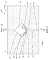
- An illustrative gas turbine engine assembly 10 includes a structural assembly 12 that also acts as a seal between a region of high pressure 18 and a region of low pressure 20.
- the seal 12 includes a first structural component 14 and a second structural component 16 which are arranged adjacently at an interface 22.
- structural components 14 and 16 may arranged so as to be supported by other structural members which support other components of the engine assembly 10 or may be structural members which are configured to form the seal 12.
- the structural components 14 and 16 in the illustrative embodiment of Fig. 1 comprise a ceramic material with each structural component 14 and 16 having a side or edge that abuts an adjacent structural component 14 or 16.
- the interface 22 between components 14 and 16 is configured so that the components 14 and 16 cooperate with a seal member 64 to form a seal between the region of high pressure 18 and the region of low pressure 20.
- the seal member 64 is an elongated rigid metal strip that is formed into two legs 40 and 46 that are separated by a bend 44.
- the seal member 64 may be resiliently pliable under pressure to allow the seal member 64 to conform and better seal the interlace 22.
- the legs 40 and 46 are bent at an angle 60 so that the legs 40 and 46 engage a surface 26 on structural component 14 and a surface 34 on structural component 16 respectively.
- High pressure gas from the region of high pressure 18 urges the legs 40 and 46 against the surfaces 26 and 34 so that the legs 40 and 46 tend to seal the region of high pressure 18 from the region of low pressure 20.
- high pressure gas is precluded from traversing the interface 22.
- the seal member 64 is retained in a space 42 that is defined when the structural components 14 and 16 are positioned in an abutting relationship.
- a portion of the space 42 is defined by the relationship of surfaces 24, 26, 28 and 30 in the side or edge of the component 14.
- the surface 24 and 30 are generally coplanar and cooperate to define a face of the edge of component 14.
- the surface 26 intersects surface 24 so that a reflex angle 62 is formed between the surface 24 and 26.
- the surface 28 intersects surface 26 so that an angle is formed therebetween.
- the angle between surfaces 28 and 26 is a right angle.
- the angle between surfaces 28 and 26 may be an obtuse angle.
- the angle between surfaces 26 and 28 may be an acute angle. Effectively, the surfaces 26 and 28 form a notch in the face of the edge of the component 14 defined by the surfaces 24 and 30.
- the surface 30 intersects the surface 28 so that a reflex angle is formed between surfaces 30 and 28.
- the angle between surfaces 30 and 28 is approximately 135°.
- the structural component 16 is formed to include surfaces 32,34,36, and 38 that mirror surfaces 24,26,28 and 30 so that the space 42 is defined when the structural components 14 and 16 are positioned in an abutting relationship. Similar to component 14, component 16 has a notch defined by surfaces 34 and 36 formed in a face defined by surfaces 32 and 38. Based on the angles 66 and 68 between the respective surfaces 34,36, and 38 that mirror surfaces 26,28 and 30, the space 42 is generally square in cross-sectional shape. The cross-sectional shape of space 42 reduces the opportunity for seal member 64 to become dislocated in the space 42 when pressure transients are experienced.
- intersections of surfaces 26, 28 and of surfaces 34, 36 may be sharp as shown in the illustrated embodiment in Fig. 1 .
- the intersections of surfaces 26, 28 and of surfaces 34, 36 may be a radius or blend as suggested in phantom in Fig. 1 .
- seal 12 formed by the structural components 14 and 16 and seal member 64 is adapted so that the interface 22 is sealed even during expansion and contraction of the adjacent components 14 and 16 that occurs during the operation of the gas turbine engine assembly 10.
- Fig. 8 it can be seen that the structure of the notch formed by surfaces 26 and 28 in the face of the structural component 14 is accessible with a direct line of sight to all of the surfaces 24, 26, 28, and 30 from the exterior of the structural component 14. This allows the surfaces 24, 26, 28, and 30 to be plasma coated with traditional spraying techniques. This permits an effective and uniform coating of oxides to be deposited on all of the surfaces 24, 26, 28, and 30.
- the discontinuity in the face of the first component 14 and the discontinuity in the face of the second component 16 form an angle with an apex of the angle positioned nearer the region of low pressure P LOW as compared the region of high pressure P HIGH .
- the discontinuity in the face of the first component 14 and the discontinuity in the face of the second component 16 may form an angle with an apex of the angle positioned nearer the region of high pressure P HIGH as compared the region of low pressure P LOW or midway between the region of high pressure P HIGH and the region of low pressure P LOW .
- a gas turbine engine assembly 410 includes a seal 412 as shown in Fig. 2 .
- the seal 412 includes the structural components 14 and 16 of the embodiment of Fig. 1 , but another embodiment of a seal member 70.
- the seal member 70 is formed from a rigid metallic strip that includes a base 54 and two wings 52 and 56 that are bent upwardly from the base 54 so that the wings 52 and 56 are bent at a 90° angle.
- the wings 52 and 56 engage the surfaces 26 and 34 respectively, and similarly to the engagement of the legs 40 and 46rigid of the seal member 64 of the embodiment of Fig. 1 .
- the base 54 is perforated with a number of through- holes 58 formed therethrough along the length of the seal member 70.
- the through- holes 58 are configured to allow some of the high pressure gas in the region of high pressure 18 to bleed through to the region of low pressure 20 for purge or cooling requirements. It should be understood that the size and number of the through-holes 58 might be varied in various applications to limit or control the flow of gas from the region of high pressure 18 to the region of low pressure 20.
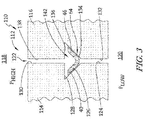
- a seal 112 is formed when two structural components 114 and 116 are positioned in an abutting relationship.
- An interface 122 is formed between the structural components 114 and 116.
- the structural component 114 includes a surface 130 that is coplanar with a surface 124 such that the two surfaces 124 and 130 define a face along the edge/side of the structural component 114.
- a notch or indentation is formed in the face by the intersection of a surface 126 with the surface 124 such that a reflex angle is formed between the surfaces 124 and 126.
- the reflex angle between the surfaces 124 and 126 is 135°.
- a surface 128 intersects the surface 130 and the surface 126.
- the surface 128 is generally perpendicular to the surface 130. In the illustrative embodiment of Fig. 3 , the angle between the surface 126 and the surface 128 is 45°.
- the structural component 116 includes surfaces 132, 134,136 and 138 which mirror the surfaces 124,126,128, and 130 when the structural component 114 is positioned to abut the structural component 116, as shown in Fig. 3 .
- the notches formed by surfaces 126 and 128 in structural component 114 and the surfaces 134 and 136 in structural component 116 cooperate to define a space 142 when the structural components 114 and 116 are positioned adjacent one another.
- the seal 112 Includes the seal member 64 discussed above with regard to the embodiment of Fig. 1 .
- the legs 40 and 46 of seal member 64 engage the surfaces 126 and 134 respectively.
- the seal member 64 acts to prevent or reduce a flow of gas from an area of high pressure 118 to an area of low pressure 120.
- the space 142 in which the seal number 64 is received is sized to limit the movement of the seal member 64 within the space 142, thereby reducing the potential for the seal member 64 to become dislodged or mis-positioned due to transients in the gas pressure.
- the structural components 114 and 116 are shown to be ceramic in Fig. 3 , it is contemplated that other materials may be used in a similar construction depending on pressures and temperatures experienced by the gas turbine engine assembly 110.
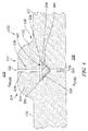
- gas turbine engine assembly 210 includes a seal 212 that is formed when the edges of a structural component 214 and the structural component 216 are positioned adjacent one another in an abutting relationship.
- the structural component 214 includes a surface 224 which is coplanar with a surface 230 and cooperate to define a face of the edge of the structural component 214.
- a notch is formed in the face, the notch being defined by a surface 226 and a surface 228.
- the surfaces 224,226,228, and 230 are arranged in the same manner as the surfaces 124,126,128, and 130, respectively.
- the structural component 216 includes surfaces 232,234,236, and 238 which are arranged in the same manner as discussed above with regard to the surfaces 132,134,136, and 138, respectively.
- the notches in the faces of the respective structural components 214 and 216 cooperate to define a space 242.
- a seal member 264 is positioned in the space 242 to seal the interface 222 between the structural components 214 and 216 to prevent the flow of gas from a region of high pressure 218 to a region of low pressure 220.
- the seal member 264 is a rigid strip of metal having a triangular cross-section.
- the structural components 214 and 216 comprise a metal, such as titanium, for example.
- the seal 212 is suitable for certain applications. Because the structural components 214 and 216 are metallic, they may be arranged and configured so that portions of the structural components 214 and 216 are thinner, thereby reducing the weight of the gas turbine engine assembly 210.
- the structural component 214 includes a body 215 and an interface member 213.
- the structural component 216 includes a body 219 and an interface member 217.
- the interface members 213 and 217 are thicker than the bodies 215 and 219. The thicker interface members 213 and 217 permit larger faces for the interface 222 between the structural components 214 and 216. This thereby allows for a larger space 242 and seal number 264 then would be possible if the structural components 214 and 216 had a uniform thickness.
- gas turbine engine assembly 310 includes a seal 312.
- the gas turbine engine assembly 310 includes the structural components 14 and 16 discussed above with regard to Fig. 1 .
- the structural components 14 and 16 are curved such that when multiple structural components 14 and 16 are placed together they will form an annular structure such as engine housing or a blade track, for example.
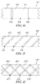
- the seal member 64 of the embodiment of Fig. 1 is omitted and replaced with a seal member 364.
- the seal member 364 is a strip of corrugated material as shown in Fig. 6 .
- the corrugations vary from a first end 366 to a second end 368 such that there are multiple raised areas 370 and multiple reduced areas 372.
- Fig. 7 it can be seen that when the seal member 364 is positioned against the surface 34 of structural component 16, a space 374 is formed between each raised area 370 and the surface 34.
- the spaces 374 provide a flow path for gas to flow from a region of high pressure 18 to a region of low pressure 20.
- the seal member 364 may be pliable and resilient such that under extreme pressures the seal member 364 deforms to close the gaps 374, thereby limiting or eliminating the flow of gas from the region of high pressure 18 to a region of low pressure 20. It is contemplated that the materials selected and dimensions of the corrugations may be adjusted to control the flow of gas through the interface 322 and the conditions required to deform the seal member 364.
- the seal member 364 may be omitted and replaced with a seal member 464 shown in Figure. 9 .
- the seal member 464 is similar to the seal member 364; however, the seal member 464 has a number of channels 474 formed along the length of the seal member 464 from a first into 466 to a second and 468.
- the channels 474 are interposed between ribs 472.
- the channels 474 provide a flow path for gas to flow past the seal member 464. It is contemplated that the location, size, number, and pattern of channels 474 may be varied for different applications to control or define the amount of flow of gas from a region of high pressure to region of low pressure when the seal member 464 is used in a particular seal.
- the channels 474 may extend in a generally straight line from a radially outer side to a radially inner side of the seal member 464.
- channels 474' may extend at an angle from a radially outer side to a radially inner side of a seal member 464'.
- channels 474" may intersect one another to form a hatched pattern as they extend from a radially outer side to a radially inner side of a seal member 464".
Landscapes
- Engineering & Computer Science (AREA)
- Mechanical Engineering (AREA)
- General Engineering & Computer Science (AREA)
- Turbine Rotor Nozzle Sealing (AREA)
- Gasket Seals (AREA)
Applications Claiming Priority (1)
| Application Number | Priority Date | Filing Date | Title |
|---|---|---|---|
| US201562155222P | 2015-04-30 | 2015-04-30 |
Publications (1)
| Publication Number | Publication Date |
|---|---|
| EP3088680A1 true EP3088680A1 (de) | 2016-11-02 |
Family
ID=55806177
Family Applications (1)
| Application Number | Title | Priority Date | Filing Date |
|---|---|---|---|
| EP16165827.3A Withdrawn EP3088680A1 (de) | 2015-04-30 | 2016-04-18 | Dichtung für einen gasturbinenmotor |
Country Status (2)
| Country | Link |
|---|---|
| US (1) | US10443419B2 (de) |
| EP (1) | EP3088680A1 (de) |
Cited By (6)
| Publication number | Priority date | Publication date | Assignee | Title |
|---|---|---|---|---|
| EP3135866A1 (de) * | 2015-08-25 | 2017-03-01 | General Electric Company | Beschichtete dichtungsschlitzsysteme für turbomaschinen und verfahren zur herstellung davon |
| EP3767076A1 (de) * | 2019-07-19 | 2021-01-20 | Raytheon Technologies Corporation | Baugruppe mit schaufelaussenluftdichtung aus keramischem matrixverbundstoff |
| EP3767075A1 (de) * | 2019-07-19 | 2021-01-20 | Raytheon Technologies Corporation | Baugruppe mit schaufelaussenluftdichtung aus keramischem matrixverbundstoff |
| US11105214B2 (en) | 2019-07-19 | 2021-08-31 | Raytheon Technologies Corporation | CMC BOAS arrangement |
| US11248482B2 (en) | 2019-07-19 | 2022-02-15 | Raytheon Technologies Corporation | CMC BOAS arrangement |
| EP4575187A1 (de) * | 2023-12-18 | 2025-06-25 | Rolls-Royce plc | Zwischenkomponentendichtungsanordnung für einen gasturbinenmotor |
Families Citing this family (20)
| Publication number | Priority date | Publication date | Assignee | Title |
|---|---|---|---|---|
| US10927692B2 (en) * | 2018-08-06 | 2021-02-23 | General Electric Company | Turbomachinery sealing apparatus and method |
| KR102168575B1 (ko) * | 2019-08-12 | 2020-10-22 | 두산중공업 주식회사 | 교환 가능한 자기 잠금식 씰링 어셈블리를 구비한 로터, 터빈 및 이를 포함하는 가스터빈 |
| US11248480B2 (en) * | 2019-09-11 | 2022-02-15 | Raytheon Technologies Corporation | Intersegment seal for CMC boas assembly |
| US11624441B2 (en) * | 2021-04-30 | 2023-04-11 | Raytheon Technologies Corporation | Reinforced brush seal assembly |
| US12188365B1 (en) | 2023-12-04 | 2025-01-07 | Rolls-Royce Corporation | Method and apparatus for ceramic matrix composite turbine shroud assembly |
| US12152499B1 (en) | 2023-12-04 | 2024-11-26 | Rolls-Royce Corporation | Turbine shroud segments with strip seal assemblies having dampened ends |
| US12286906B1 (en) | 2023-12-04 | 2025-04-29 | Rolls-Royce Corporation | Locating plate for use with turbine shroud assemblies |
| US12286885B1 (en) | 2023-12-04 | 2025-04-29 | Rolls-Royce Corporation | Turbine assembly with confronting vane and turbine shroud segment |
| US12158072B1 (en) | 2023-12-04 | 2024-12-03 | Rolls-Royce Corporation | Turbine shroud segments with damping strip seals |
| US12241376B1 (en) | 2023-12-04 | 2025-03-04 | Rolls-Royce Corporation | Locating plate for use with turbine shroud assemblies |
| US12421862B2 (en) | 2023-12-04 | 2025-09-23 | Rolls-Royce Corporation | Turbine shroud assembly with angled cooling holes |
| US12421870B1 (en) | 2024-04-30 | 2025-09-23 | Rolls-Royce Corporation | Pin mounted ceramic matrix composite heat shields with impingement cooling |
| US12258880B1 (en) | 2024-05-30 | 2025-03-25 | Rolls-Royce Corporation | Turbine shroud assemblies with inter-segment strip seal |
| US12305525B1 (en) | 2024-05-30 | 2025-05-20 | Rolls-Royce Corporation | Turbine shroud assemblies with rod seal and strip seals |
| US12215593B1 (en) | 2024-05-30 | 2025-02-04 | Rolls-Royce Corporation | Turbine shroud assembly with inter-segment damping |
| US12416241B1 (en) | 2024-05-30 | 2025-09-16 | Rolls-Royce Corporation | Turbine shroud assemblies with strip seals |
| US12410725B1 (en) | 2024-05-31 | 2025-09-09 | Rolls-Royce Corporation | Turbine shroud assemblies with air activated pistons for biasing buffer cavity seals |
| US12577881B2 (en) | 2024-05-31 | 2026-03-17 | Rolls-Royce Corporation | Turbine shroud assemblies with anti-migration seals |
| US12352176B1 (en) | 2024-05-31 | 2025-07-08 | Rolls-Royce Corporation | Turbine shroud assemblies with channels for buffer cavity seal thermal management |
| US12228044B1 (en) | 2024-06-26 | 2025-02-18 | Rolls-Royce Corporation | Turbine shroud system with ceramic matrix composite segments and dual inter-segment seals |
Citations (5)
| Publication number | Priority date | Publication date | Assignee | Title |
|---|---|---|---|---|
| US3728041A (en) * | 1971-10-04 | 1973-04-17 | Gen Electric | Fluidic seal for segmented nozzle diaphragm |
| US4767260A (en) * | 1986-11-07 | 1988-08-30 | United Technologies Corporation | Stator vane platform cooling means |
| EP1452694A2 (de) * | 2003-02-26 | 2004-09-01 | ROLLS-ROYCE plc | Dämpfungs- und Dichtungselement für Turbine |
| WO2005095763A1 (de) * | 2004-03-31 | 2005-10-13 | Alstom Technology Ltd | Spaltdichtung zum abdichten eines spalts zwischen zwei benachbarten bauteilen |
| US20070297900A1 (en) * | 2006-06-23 | 2007-12-27 | Snecma | Sector of a compressor guide vanes assembly or a sector of a turbomachine nozzle assembly |
Family Cites Families (21)
| Publication number | Priority date | Publication date | Assignee | Title |
|---|---|---|---|---|
| US177411A (en) * | 1876-05-16 | Improvement in reed-organs | ||
| IT1131142B (it) | 1980-05-06 | 1986-06-18 | Nuovo Pignone Spa | Guarnizione anulare di tenuta statica per altissime temperature e bassi salti di pressione e procedimento per realizzarla |
| US4336943A (en) | 1980-11-14 | 1982-06-29 | United Technologies Corporation | Wedge-shaped seal for flanged joints |
| US5076591A (en) | 1988-12-22 | 1991-12-31 | General Electric Company | Gas leakage seal |
| US5088888A (en) * | 1990-12-03 | 1992-02-18 | General Electric Company | Shroud seal |
| US5158305A (en) | 1992-01-31 | 1992-10-27 | Eg&G Pressure Science, Inc. | Pressure-energized two-element seal |
| DE4215440A1 (de) | 1992-05-11 | 1993-11-18 | Mtu Muenchen Gmbh | Einrichtung zur Bauteilabdichtung, insbesondere bei Turbomaschinen |
| US5630593A (en) | 1994-09-12 | 1997-05-20 | Eg&G Pressure Science, Inc. | Pressure-energized sealing rings |
| US6568692B2 (en) | 2001-03-02 | 2003-05-27 | Honeywell International, Inc. | Low stress seal |
| US6599089B2 (en) * | 2001-12-28 | 2003-07-29 | General Electric Company | Supplemental seal for the chordal hinge seal in a gas turbine |
| US6648333B2 (en) | 2001-12-28 | 2003-11-18 | General Electric Company | Method of forming and installing a seal |
| JP4577813B2 (ja) | 2003-08-20 | 2010-11-10 | イーグル・エンジニアリング・エアロスペース株式会社 | シール装置 |
| US20060025683A1 (en) * | 2004-07-30 | 2006-02-02 | Ahof Biophysical Systems Inc. | Hand-held imaging probe for treatment of states of low blood perfusion |
| JP4727934B2 (ja) | 2004-02-20 | 2011-07-20 | イーグル・エンジニアリング・エアロスペース株式会社 | シール装置 |
| US20060007842A1 (en) * | 2004-07-06 | 2006-01-12 | Epo Science & Technology Inc. | Cleaning disc for cleaning roller in drive |
| GB2418966B (en) * | 2004-10-11 | 2006-11-15 | Rolls Royce Plc | A sealing arrangement |
| US7654734B2 (en) * | 2005-05-10 | 2010-02-02 | General Electric Company | Methods and devices for evaluating the thermal exposure of a metal article |
| US7726936B2 (en) | 2006-07-25 | 2010-06-01 | Siemens Energy, Inc. | Turbine engine ring seal |
| US8128343B2 (en) | 2007-09-21 | 2012-03-06 | Siemens Energy, Inc. | Ring segment coolant seal configuration |
| US8201834B1 (en) * | 2010-04-26 | 2012-06-19 | Florida Turbine Technologies, Inc. | Turbine vane mate face seal assembly |
| US20130177411A1 (en) * | 2012-01-05 | 2013-07-11 | General Electric Company | System and method for sealing a gas path in a turbine |
-
2016
- 2016-03-25 US US15/081,399 patent/US10443419B2/en active Active
- 2016-04-18 EP EP16165827.3A patent/EP3088680A1/de not_active Withdrawn
Patent Citations (5)
| Publication number | Priority date | Publication date | Assignee | Title |
|---|---|---|---|---|
| US3728041A (en) * | 1971-10-04 | 1973-04-17 | Gen Electric | Fluidic seal for segmented nozzle diaphragm |
| US4767260A (en) * | 1986-11-07 | 1988-08-30 | United Technologies Corporation | Stator vane platform cooling means |
| EP1452694A2 (de) * | 2003-02-26 | 2004-09-01 | ROLLS-ROYCE plc | Dämpfungs- und Dichtungselement für Turbine |
| WO2005095763A1 (de) * | 2004-03-31 | 2005-10-13 | Alstom Technology Ltd | Spaltdichtung zum abdichten eines spalts zwischen zwei benachbarten bauteilen |
| US20070297900A1 (en) * | 2006-06-23 | 2007-12-27 | Snecma | Sector of a compressor guide vanes assembly or a sector of a turbomachine nozzle assembly |
Cited By (9)
| Publication number | Priority date | Publication date | Assignee | Title |
|---|---|---|---|---|
| EP3135866A1 (de) * | 2015-08-25 | 2017-03-01 | General Electric Company | Beschichtete dichtungsschlitzsysteme für turbomaschinen und verfahren zur herstellung davon |
| US10100656B2 (en) | 2015-08-25 | 2018-10-16 | General Electric Company | Coated seal slot systems for turbomachinery and methods for forming the same |
| EP3767076A1 (de) * | 2019-07-19 | 2021-01-20 | Raytheon Technologies Corporation | Baugruppe mit schaufelaussenluftdichtung aus keramischem matrixverbundstoff |
| EP3767075A1 (de) * | 2019-07-19 | 2021-01-20 | Raytheon Technologies Corporation | Baugruppe mit schaufelaussenluftdichtung aus keramischem matrixverbundstoff |
| US11073037B2 (en) | 2019-07-19 | 2021-07-27 | Raytheon Technologies Corporation | CMC BOAS arrangement |
| US11073038B2 (en) | 2019-07-19 | 2021-07-27 | Raytheon Technologies Corporation | CMC BOAS arrangement |
| US11105214B2 (en) | 2019-07-19 | 2021-08-31 | Raytheon Technologies Corporation | CMC BOAS arrangement |
| US11248482B2 (en) | 2019-07-19 | 2022-02-15 | Raytheon Technologies Corporation | CMC BOAS arrangement |
| EP4575187A1 (de) * | 2023-12-18 | 2025-06-25 | Rolls-Royce plc | Zwischenkomponentendichtungsanordnung für einen gasturbinenmotor |
Also Published As
| Publication number | Publication date |
|---|---|
| US20160319687A1 (en) | 2016-11-03 |
| US10443419B2 (en) | 2019-10-15 |
Similar Documents
| Publication | Publication Date | Title |
|---|---|---|
| US10443419B2 (en) | Seal for a gas turbine engine assembly | |
| EP3327254B1 (de) | Dichtungsanordnung für gasturbinenmotorkomponenten | |
| EP3088679A1 (de) | Dichtung für eine gasturbinenmotorbaugruppe | |
| US20170058689A1 (en) | Sealing element for a turbo-machine, turbo-machine comprising a sealing element and method for manufacturing a sealing element | |
| US9759079B2 (en) | Split line flow path seals | |
| EP2886803A1 (de) | Dichtung für Gasturbinenmotoren | |
| EP2836748B1 (de) | Duplexfingerdichtung für verbindungsstellen mit hoher relativer verschiebung | |
| US20180030896A1 (en) | Acoustic liners and method of shaping an inlet of an acoustic liner | |
| EP2105582A2 (de) | Gasturbinendichtungsanordnung sowie Gasturbine mit einer solchen Dichtungsanordnung | |
| EP3276152A1 (de) | Auskleidungsanordnung, motorgehäuse und verfahren zur montage davon | |
| EP1873426B1 (de) | Dichtungsanordnung | |
| US9453422B2 (en) | Device, system and method for preventing leakage in a turbine | |
| JP2016217349A (ja) | スロット付きピンを有するタービンブレードダンパーシステム | |
| RU2521526C1 (ru) | Уплотнительное металлическое кольцо и фланцевое уплотнительное устройство с перепуском рабочей среды | |
| EP3176474B1 (de) | Kombinationsölring | |
| US8950751B2 (en) | Compliant element | |
| KR102318300B1 (ko) | 터보기계의 구성요소의 제조 방법, 터보기계의 구성요소 및 터보기계 | |
| US10619671B2 (en) | Roller bearing cage and method for mounting a roller bearing cage | |
| EP3236113A1 (de) | Verbesserungen an oder in zusammenhang mit metall-metall-dichtungen | |
| JP6941674B2 (ja) | タービンのためのシールセグメント、タービンの流路の外側の境界を定めるための組立体、およびステータ/ロータシール | |
| KR200499581Y1 (ko) | 시일, 이러한 시일을 갖는 진공 시스템 및 이러한 시일의 제조 방법 | |
| US20170306904A1 (en) | Intake noise reduction device | |
| US20190107017A1 (en) | Device for depositing oil droplets and/or oil mist | |
| US10280783B2 (en) | Turbomachinery blade outer air seal | |
| EP2487331B1 (de) | Komponente einer Turbinenschaufelplattform |
Legal Events
| Date | Code | Title | Description |
|---|---|---|---|
| PUAI | Public reference made under article 153(3) epc to a published international application that has entered the european phase |
Free format text: ORIGINAL CODE: 0009012 |
|
| AK | Designated contracting states |
Kind code of ref document: A1 Designated state(s): AL AT BE BG CH CY CZ DE DK EE ES FI FR GB GR HR HU IE IS IT LI LT LU LV MC MK MT NL NO PL PT RO RS SE SI SK SM TR |
|
| AX | Request for extension of the european patent |
Extension state: BA ME |
|
| 17P | Request for examination filed |
Effective date: 20170426 |
|
| RBV | Designated contracting states (corrected) |
Designated state(s): AL AT BE BG CH CY CZ DE DK EE ES FI FR GB GR HR HU IE IS IT LI LT LU LV MC MK MT NL NO PL PT RO RS SE SI SK SM TR |
|
| STAA | Information on the status of an ep patent application or granted ep patent |
Free format text: STATUS: REQUEST FOR EXAMINATION WAS MADE |
|
| STAA | Information on the status of an ep patent application or granted ep patent |
Free format text: STATUS: EXAMINATION IS IN PROGRESS |
|
| 17Q | First examination report despatched |
Effective date: 20180910 |
|
| STAA | Information on the status of an ep patent application or granted ep patent |
Free format text: STATUS: THE APPLICATION HAS BEEN WITHDRAWN |
|
| 18W | Application withdrawn |
Effective date: 20200330 |