EP3088686A1 - Système d'huile modulé de contrôleur pour un système de propulsion à turbine à gaz - Google Patents
Système d'huile modulé de contrôleur pour un système de propulsion à turbine à gaz Download PDFInfo
- Publication number
- EP3088686A1 EP3088686A1 EP16164109.7A EP16164109A EP3088686A1 EP 3088686 A1 EP3088686 A1 EP 3088686A1 EP 16164109 A EP16164109 A EP 16164109A EP 3088686 A1 EP3088686 A1 EP 3088686A1
- Authority
- EP
- European Patent Office
- Prior art keywords
- propulsion system
- lubricant
- pump
- operating condition
- system controller
- Prior art date
- Legal status (The legal status is an assumption and is not a legal conclusion. Google has not performed a legal analysis and makes no representation as to the accuracy of the status listed.)
- Withdrawn
Links
- 239000000314 lubricant Substances 0.000 claims abstract description 197
- 238000005461 lubrication Methods 0.000 claims abstract description 30
- 238000010248 power generation Methods 0.000 claims abstract description 20
- 238000000034 method Methods 0.000 claims description 23
- 230000004044 response Effects 0.000 claims description 8
- 238000005516 engineering process Methods 0.000 abstract description 3
- 238000007726 management method Methods 0.000 description 16
- 238000004891 communication Methods 0.000 description 11
- 230000006870 function Effects 0.000 description 7
- 238000010586 diagram Methods 0.000 description 5
- 238000013500 data storage Methods 0.000 description 4
- 238000013461 design Methods 0.000 description 3
- 238000003491 array Methods 0.000 description 2
- 238000002485 combustion reaction Methods 0.000 description 2
- 239000012530 fluid Substances 0.000 description 2
- 239000000446 fuel Substances 0.000 description 2
- 238000012545 processing Methods 0.000 description 2
- 238000012546 transfer Methods 0.000 description 2
- 230000005540 biological transmission Effects 0.000 description 1
- 230000009194 climbing Effects 0.000 description 1
- 238000001816 cooling Methods 0.000 description 1
- 230000000694 effects Effects 0.000 description 1
- 238000012423 maintenance Methods 0.000 description 1
- 230000007246 mechanism Effects 0.000 description 1
- 238000012986 modification Methods 0.000 description 1
- 230000004048 modification Effects 0.000 description 1
- 230000003287 optical effect Effects 0.000 description 1
- 238000005457 optimization Methods 0.000 description 1
- 230000002085 persistent effect Effects 0.000 description 1
- 230000008569 process Effects 0.000 description 1
- 230000001737 promoting effect Effects 0.000 description 1
- 238000005086 pumping Methods 0.000 description 1
- 238000000926 separation method Methods 0.000 description 1
- 238000012360 testing method Methods 0.000 description 1
Images


Classifications
-
- F—MECHANICAL ENGINEERING; LIGHTING; HEATING; WEAPONS; BLASTING
- F02—COMBUSTION ENGINES; HOT-GAS OR COMBUSTION-PRODUCT ENGINE PLANTS
- F02C—GAS-TURBINE PLANTS; AIR INTAKES FOR JET-PROPULSION PLANTS; CONTROLLING FUEL SUPPLY IN AIR-BREATHING JET-PROPULSION PLANTS
- F02C7/00—Features, components parts, details or accessories, not provided for in, or of interest apart form groups F02C1/00 - F02C6/00; Air intakes for jet-propulsion plants
- F02C7/06—Arrangements of bearings; Lubricating
-
- F—MECHANICAL ENGINEERING; LIGHTING; HEATING; WEAPONS; BLASTING
- F01—MACHINES OR ENGINES IN GENERAL; ENGINE PLANTS IN GENERAL; STEAM ENGINES
- F01D—NON-POSITIVE DISPLACEMENT MACHINES OR ENGINES, e.g. STEAM TURBINES
- F01D25/00—Component parts, details, or accessories, not provided for in, or of interest apart from, other groups
- F01D25/18—Lubricating arrangements
- F01D25/20—Lubricating arrangements using lubrication pumps
Definitions
- the present disclosure relates generally to control systems used in gas turbine propulsion systems, and more specifically to control of an oil subsystem used for lubrication and cooling of the propulsion system.
- Gas turbine propulsion systems are used to power aircraft, watercraft, power generators, and the like.
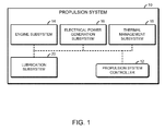
- a typical gas turbine propulsion system includes a gas turbine engine subsystem, an electrical power generation subsystem, a thermal management subsystem, and a lubrication subsystem.
- Typical lubrication subsystems include a lubricant pump that circulates oil to various sumps of the propulsion system on a set schedule and/or flow rate.
- the lubricant pump may be mechanically driven by an engine gearbox of the engine subsystem.
- Certain lubrication subsystems may include individual sub-circuits to distribute lubricant to individual bearing sumps and other locations throughout the engine on a set schedule and/or flow rate.
- a gas turbine engine propulsion system may include a plurality of lubricant pumps, a plurality of lubricant circuits, and a propulsion system controller.
- Each of the plurality of lubricant circuits includes a corresponding lubricated component of the propulsion system and is coupled to a corresponding lubricant pump.
- the propulsion system controller is configured to receive input data indicative of a current operating condition of the propulsion system, determine a plurality of pump control settings based on the current operating condition, and control each of the plurality of lubricant pumps according to a corresponding pump control setting of the plurality of pump control settings.
- the input data indicative of the current operating condition of the propulsion system may include input data indicative of a lubricant flow rate, a lubricant pressure, or a lubricant temperature of the propulsion system. In some embodiments, the input data indicative of the current operating condition of the propulsion system may include input data indicative of an engine subsystem load or an electrical power generation subsystem load of the propulsion system.
- the propulsion system may further include a gas turbine engine bearing, wherein a corresponding lubricated component of the propulsion system includes the gas turbine engine bearing.
- the propulsion system may further include a heat exchanger, wherein a corresponding lubricated component of the propulsion system includes the heat exchanger.
- the propulsion system controller may be further configured to determine whether a lubricant pump of the plurality of lubricant pumps has failed, and, in response to a determination that a lubricant pump has failed, control a valve of the propulsion system to redirect a lubricant circuit associated with the failed lubricant pump to provide lubricant to the corresponding lubricated component.
- receiving the input data indicative of the current operating condition of the propulsion system may include receiving input data indicative of a lubricant flow rate, a lubricant pressure, or a lubricant temperature of the propulsion system. In some embodiments, receiving the input data indicative of the current operating condition of the propulsion system may include receiving input data indicative of an engine subsystem load or an electrical power generation subsystem load of the propulsion system.
- the method may further include determining, by the propulsion system controller, whether a lubricant pump of the plurality of lubricant pumps has failed; and in response to determining that a lubricant pump has failed, controlling, by the propulsion system controller, a valve of the propulsion system to redirect a lubricant circuit associated with the failed lubricant pump to provide lubricant to the corresponding lubricated component.
- a propulsion system controller may include pump control logic to receive input data indicative of a current operating condition of a propulsion system; determine a plurality of pump control settings based on the current operating condition; and control each of a plurality of lubricant pumps of the propulsion system according to a corresponding pump control setting of the plurality of pump control settings, wherein each of the plurality of lubricant pumps is coupled to a corresponding lubricant circuit of the propulsion system and each lubricant circuit includes a corresponding lubricated component of the propulsion system.
- to receive the input data indicative of the current operating condition of the propulsion system may include to receive input data indicative of a lubricant flow rate, a lubricant pressure, or a lubricant temperature of the propulsion system. In some embodiments, to receive the input data indicative of the current operating condition of the propulsion system may include to receive input data indicative of an engine subsystem load or an electrical power generation subsystem load of the propulsion system.
- the pump control logic may be further configured to receive input data indicative of a pre-programmed operating condition of the propulsion system; and determine the plurality of pump control settings based on the pre-programmed operating condition.
- to determine the plurality of pump control settings based on the current operating condition may include to determine a pump control setting for a corresponding lubricant pump to achieve a target lubricant flow rate, a target lubricant pressure, or a target lubricant temperature.
- the propulsion system controller may further include pump failure logic to determine whether a lubricant pump of the plurality of lubricant pumps has failed; and, in response to a determination that a lubricant pump has failed, control a valve of the propulsion system to redirect a lubricant circuit associated with the failed lubricant pump to provide lubricant to the corresponding lubricated component.
- the engine subsystem 14 may be adapted to provide thrust or shaft power to an associated vehicle or system (e.g. plane, ship, generator, pump, or the like).
- the engine subsystem 14 may include a gas turbine engine, including a compressor, a combustor, a turbine, a gearbox, and other components typically included in a gas turbine engine.
- the thermal management subsystem 18 is configured to control the temperature of various components of the propulsion system 10 and/or an associated vehicle or system (e.g. plane, ship, generator, pump, or the like).
- the thermal management subsystem 18 may include heat exchangers, radiators, or other components capable of controlling the temperature of various components of the propulsion system 10 and/or the associated vehicle or system.
- the lubrication subsystem 20 distributes a lubricant such as oil to the other subsystems of the propulsion system 10 to provide lubrication and/or thermal management.
- a lubricant such as oil
- the lubrication subsystem 20 includes several lubricant circuits that each include a distributed electric pump that is controlled by the propulsion system controller 12.
- Each of the lubricated components 24 may be embodied as any component of the propulsion system 10 that uses lubricant supplied by the lubrication subsystem 20, for example for lubrication and/or thermal management purposes.
- the lubricated components 24 may be included in, coupled with, or otherwise interfaced with other subsystems of the propulsion system 10, such as the engine subsystem 14, the electrical power generation subsystem 16, and the thermal management subsystem 18.
- the lubricated components 24 include a low-pressure generator 34, a front engine sump 36, a heat exchanger 38, an engine gearbox 40, an intermediate engine sump 42, a high-pressure generator 44, and a rear engine sump 46.
- the low-pressure generator 34 and the high-pressure generator 44 may be embodied as AC generators or other electrical machines used to convert mechanical energy into electrical energy.
- the low-pressure generator 34 and the high-pressure generator 44 may be configured to generate power using low-pressure exhaust and high-pressure exhaust of the gas turbine engine, respectively.
- the generators 34, 44 may be included in the electrical power generation subsystem 16. Although illustrated as including two generators 34, 44, it should be understood that in some embodiments, the electrical power generation subsystem 16 may include one generator or more than two generators.
- the front engine sump 36, the engine gearbox 40, the intermediate engine sump 42, and the rear engine sump 46 may be embodied as engine bearing sumps or other components used to provide lubrication to components of the gas turbine engine and/or a transmission coupled to the gas turbine engine.
- part or all of the engine sumps 36, 42, 46 and the engine gearbox 40 may be included in the engine subsystem 14.
- the engine subsystem may include any number of engine bearing sumps. Additionally, it should be understood that in some embodiments the engine subsystem 14 may not include an engine gearbox 40.
- the heat exchanger 38 may be embodied as any component or components used to transfer heat to or from the oil or other lubricant pumped through the heat exchanger 38.
- the heat exchanger 38 may be used to remove heat from other components of the gas turbine engine.
- the heat exchanger 38 may be used to transfer heat from the lubricant to the fuel of the vehicle or system associated with the propulsion system 10.
- the heat exchanger 38 may be included in the thermal management subsystem 18. Although illustrated as including a single heat exchanger 38, it should be understood that in some embodiments, the thermal management subsystem 18 may include two or more heat exchangers 38.
- the pumps 28 are connected to the propulsion system controller 12 by a data bus 32.
- the data bus 32 may be embodied as any network interface, electrical connection, optical connection, wireless connection, or other control interface capable of transmitting control instructions from the propulsion system controller 12 to the pumps 28. Although illustrated as a data bus 32, it should be understood that in some embodiments the propulsion system controller 12 may be coupled to the pumps 28 using any appropriate communication technology or topology, such as one or more point-to-point communication links.
- the pump control logic 22 may be embodied as hardware, firmware, software, or a combination thereof.
- the pump control logic 22 may form a portion of, or otherwise be established by, a processor or other hardware components of the propulsion system controller 12.
- the pump control logic 22 may be embodied as a circuit or collection of electrical devices (e.g., a pump control logic circuit).
- the pump control logic 22 is configured to receive input data indicative of a current operating condition of the propulsion system 10 and determine a plurality of pump control settings based on the current operating condition.
- the pump control logic 22 is further configured to control each of the lubricant pumps 28 of the propulsion system 10 according to a corresponding pump control setting of the plurality of pump control settings.
- the illustrative lubrication subsystem 20' includes the oil sump 26 and two lubricant pumps 28a, 28b connected to two lubricant circuits 30a, 30b, respectively. As shown, the lubricant circuits 30a, 30b supply lubricant to two lubricated components 24a, 24b, respectively.
- the lubrication subsystem 20' further includes a valve 50 connected between the lubricant circuits 30a, 30b.
- the valve 50 may be embodied as any electrically operable fluid control valve.
- valve 50 When opened, the valve 50 allows fluid pumped by the pump 28b to be supplied to the lubricant circuit 30a and thereby be supplied to the lubricated component 24a. Thus, as further described below, the valve 50 may be opened to allow the lubricated component 24a to receive lubricant if the lubricant pump 28a fails.
- the valve 50 is connected to the data bus 32 and may be controlled by the propulsion system controller 12. Although illustrated as being connected to the data bus 32, it should be understood that the in some embodiments the valve 50 may be connected to the propulsion system controller 12 using any appropriate communication technology or topology, such as one or more point-to-point communication links.
- the lubrication subsystem 20 may include multiple valves 50 that may be used to redirect lubricant among the lubricant circuits 30 of the lubrication subsystem 20.
- the pump failure logic 48 is configured to determine whether a lubricant pump 28 has failed and, in response to a determination that the lubricant pump 28 has failed, control a valve 50 of the propulsion system 10 to redirect a lubricant circuit 30 associated with the failed lubricant pump 28 to provide lubricant to the corresponding lubricated component 24.
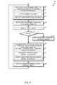
- an illustrative method 100 that may be executed by the propulsion system 10 (e.g., by the propulsion system controller 12) is shown. Aspects of the method 100 may be embodied as electrical circuitry, computerized programs, routines, logic, and/or instructions, such as the pump control logic 22 and/or the pump failure logic 48. The illustrative method 100 may be executed by the propulsion system 10 in real time during normal operation of a turbine-engine-powered vehicle/system or in an offline environment (e.g., during propulsion system testing or aircraft maintenance).
- the propulsion system controller 12 may receive pre-programmed information indicative of the operating condition of the propulsion system 10.
- the pre-programmed information may be embodied as any data indicative of a predefined operating mode or other predefined function of the propulsion system 10.
- the predefined operating mode or function may or may not correspond to the current operating condition of the propulsion system 10.
- the pre-programmed information may indicate that the gas turbine engine will be started soon, or that the gas turbine engine has recently been shut down.
- the propulsion system controller 12 may adjust the target lubricant flow rate, the target lubricant pressure, and/or the target thermal management based on a pre-programmed operating condition. Continuing that example, the propulsion system controller 12 may set the target lubricant flow and/or the target thermal management to cycle oil through the components of the propulsion system 10 prior to starting the gas turbine engine. As another example, the propulsion system controller 12 may set the target lubricant flow and/or the target thermal management to continue to provide oil to the heat exchanger 38 and/or other components of the propulsion system 10 after the gas turbine engine has been shut down, which may remove excess heat from the propulsion system 10.
- the illustrative propulsion system controller 12 includes at least one processor 210, an input/output (I/O) subsystem 212, and a memory 214.
- the I/O subsystem 212 typically includes, among other things, an I/O controller, a memory controller, and one or more I/O ports, although not specifically shown.
- the processor 210 and the I/O subsystem 212 are communicatively coupled to the memory 214.
- the memory 214 may be embodied as any type of suitable computer memory device (e.g., volatile memory such as various forms of random access memory).
- the I/O subsystem 212 is communicatively coupled to a number of hardware and/or software components, including a data storage device 216 and communication circuitry 218.
- an embodiment may include a particular feature, structure, or characteristic, but every embodiment may not necessarily include the particular feature, structure, or characteristic. Such phrases are not necessarily referring to the same embodiment. Further, when a particular feature, structure, or characteristic is described in connection with an embodiment, it is believed to be within the knowledge of one skilled in the art to effect such feature, structure, or characteristic in connection with other embodiments whether or not explicitly indicated.
- Embodiments in accordance with the disclosure may be implemented in hardware, firmware, software, or any combination thereof. Embodiments may also be implemented as instructions stored using one or more machine-readable media, which may be read and executed by one or more processors.
- a machine-readable medium may include any mechanism for storing or transmitting information in a form readable by a machine.
- a machine-readable medium may include any suitable form of volatile or non-volatile memory.
- Modules, data structures, and the like defined herein are defined as such for ease of discussion, and are not intended to imply that any specific implementation details are required.
- any of the described modules and/or data structures may be combined or divided into sub-modules, sub-processes or other units of computer code or data as may be required by a particular design or implementation.
Landscapes
- Engineering & Computer Science (AREA)
- Mechanical Engineering (AREA)
- General Engineering & Computer Science (AREA)
- Chemical & Material Sciences (AREA)
- Combustion & Propulsion (AREA)
- Control Of Turbines (AREA)
Applications Claiming Priority (1)
| Application Number | Priority Date | Filing Date | Title |
|---|---|---|---|
| US201562153804P | 2015-04-28 | 2015-04-28 |
Publications (1)
| Publication Number | Publication Date |
|---|---|
| EP3088686A1 true EP3088686A1 (fr) | 2016-11-02 |
Family
ID=55701789
Family Applications (1)
| Application Number | Title | Priority Date | Filing Date |
|---|---|---|---|
| EP16164109.7A Withdrawn EP3088686A1 (fr) | 2015-04-28 | 2016-04-06 | Système d'huile modulé de contrôleur pour un système de propulsion à turbine à gaz |
Country Status (3)
| Country | Link |
|---|---|
| US (1) | US20160319745A1 (fr) |
| EP (1) | EP3088686A1 (fr) |
| CA (1) | CA2924853A1 (fr) |
Families Citing this family (7)
| Publication number | Priority date | Publication date | Assignee | Title |
|---|---|---|---|---|
| US11162419B2 (en) * | 2018-02-12 | 2021-11-02 | General Electric Company | Method and structure for operating engine with bowed rotor condition |
| US11428164B2 (en) | 2019-02-21 | 2022-08-30 | Rolls-Royce Corporation | Gas turbine engine with scalable pumping system |
| US11970973B2 (en) * | 2020-08-07 | 2024-04-30 | Rolls-Royce Corporation | Electric machine cooling of stator with tube |
| US11629640B2 (en) | 2021-09-08 | 2023-04-18 | Rolls-Royce North American Technologies Inc. | Oil pumping control for electrical oil pumping system |
| US11702990B2 (en) | 2021-09-08 | 2023-07-18 | Rolls-Royce North American Technologies Inc. | Redundant electrically driven fuel and oil pumping system for gas turbine with bidirectional pump motor |
| FR3129375B1 (fr) * | 2021-11-25 | 2026-01-30 | Safran | Système de conversion et de transport d'énergie électrique pour l'hybridation interne d'une turbomachine d'aéronef |
| US12270337B1 (en) * | 2023-11-03 | 2025-04-08 | General Electric Company | Gas turbine engine oil flow control system |
Citations (4)
| Publication number | Priority date | Publication date | Assignee | Title |
|---|---|---|---|---|
| US20060054406A1 (en) * | 2004-07-23 | 2006-03-16 | Honeywell International Inc. | Active gas turbine lubrication system flow control |
| EP2025881A2 (fr) * | 2007-08-08 | 2009-02-18 | Honeywell International Inc. | Pompe de lubrification à entraînement motorisé et pronostic de système de lubrification et système et procédé de surveillance de l'état de ce système |
| US20100023169A1 (en) * | 2007-07-06 | 2010-01-28 | Honeywell International, Inc. | Electric Motor Driven Lubrication Pump Control System And Method That Accomodates Turbomachine Windmill Operation |
| US20160258267A1 (en) * | 2015-03-04 | 2016-09-08 | Stewart & Stevenson, LLC | Well fracturing systems with electrical motors and methods of use |
Family Cites Families (1)
| Publication number | Priority date | Publication date | Assignee | Title |
|---|---|---|---|---|
| JPH08118967A (ja) * | 1994-10-27 | 1996-05-14 | Yamaha Motor Co Ltd | エンジンの車載構造 |
-
2016
- 2016-02-19 US US15/048,259 patent/US20160319745A1/en not_active Abandoned
- 2016-03-23 CA CA2924853A patent/CA2924853A1/fr not_active Abandoned
- 2016-04-06 EP EP16164109.7A patent/EP3088686A1/fr not_active Withdrawn
Patent Citations (4)
| Publication number | Priority date | Publication date | Assignee | Title |
|---|---|---|---|---|
| US20060054406A1 (en) * | 2004-07-23 | 2006-03-16 | Honeywell International Inc. | Active gas turbine lubrication system flow control |
| US20100023169A1 (en) * | 2007-07-06 | 2010-01-28 | Honeywell International, Inc. | Electric Motor Driven Lubrication Pump Control System And Method That Accomodates Turbomachine Windmill Operation |
| EP2025881A2 (fr) * | 2007-08-08 | 2009-02-18 | Honeywell International Inc. | Pompe de lubrification à entraînement motorisé et pronostic de système de lubrification et système et procédé de surveillance de l'état de ce système |
| US20160258267A1 (en) * | 2015-03-04 | 2016-09-08 | Stewart & Stevenson, LLC | Well fracturing systems with electrical motors and methods of use |
Also Published As
| Publication number | Publication date |
|---|---|
| CA2924853A1 (fr) | 2016-10-28 |
| US20160319745A1 (en) | 2016-11-03 |
Similar Documents
| Publication | Publication Date | Title |
|---|---|---|
| EP3088686A1 (fr) | Système d'huile modulé de contrôleur pour un système de propulsion à turbine à gaz | |
| US9586690B2 (en) | Hybrid turbo electric aero-propulsion system control | |
| CN113253609B (zh) | 具有智能自适应控制的混合能量存储系统优化策略 | |
| US9593591B2 (en) | Engine health monitoring and power allocation control for a turbine engine using electric generators | |
| EP3667047B1 (fr) | Systèmes de carburant à flux de dérivation réduit | |
| JP6313756B2 (ja) | ヘリコプタの補助動力モータと主エンジンとの間の動力の最適化した伝達方法および構造 | |
| EP3530909B1 (fr) | Systèmes de pompe à carburant pour turbomachines | |
| US10233768B1 (en) | Apparatus and process for optimizing turbine engine performance via load control through a power control module | |
| US7876061B2 (en) | Power system with multiple generator units | |
| EP3067535B1 (fr) | Turbine à flux de retour | |
| US11441490B2 (en) | Hydraulic braking and power extraction for rotational machines | |
| US11015525B2 (en) | Methods, computer programs, non transitory computer readable storage mediums, signals, and apparatus for controlling electrical power supplied to a component of a vehicle | |
| CN114622997A (zh) | 操作飞行器发动机的方法和使用多种燃料类型的燃料系统 | |
| EP2937519A1 (fr) | Procédé de commande d'un générateur de démarrage électrique pour moteurs à turbine à gaz | |
| US20080297075A1 (en) | Power system with multiple generator units | |
| EP4148253B1 (fr) | Système redondant de pompage de carburant et d'huile à entraînement électrique pour turbine à gaz avec moteur à pompe bidirectionnel | |
| US20230072590A1 (en) | Redundant electrically driven fuel and oil pumping system for gas turbines | |
| US10934889B2 (en) | System and method for supplying lubrication fluid to at least one member of an aircraft propulsion assembly | |
| US20230076951A1 (en) | Electrically driven redundant fuel and oil pumping system for gas turbine engines | |
| EP2835521A1 (fr) | Dispositif de contrôle de génération d'électricité d'un navire, navire, et procédé de contrôle de génération d'électricité de navire | |
| KR20160023371A (ko) | 선박의 폐열을 이용한 전력 생산 장치 및 방법 | |
| Thirunavukarasu et al. | Evaluation of gas turbine engine dynamic interaction with electrical and thermal system | |
| US12534209B2 (en) | Autonomous air conditioning system for aircraft | |
| POWER | 3. iIlil |
Legal Events
| Date | Code | Title | Description |
|---|---|---|---|
| PUAI | Public reference made under article 153(3) epc to a published international application that has entered the european phase |
Free format text: ORIGINAL CODE: 0009012 |
|
| AK | Designated contracting states |
Kind code of ref document: A1 Designated state(s): AL AT BE BG CH CY CZ DE DK EE ES FI FR GB GR HR HU IE IS IT LI LT LU LV MC MK MT NL NO PL PT RO RS SE SI SK SM TR |
|
| AX | Request for extension of the european patent |
Extension state: BA ME |
|
| STAA | Information on the status of an ep patent application or granted ep patent |
Free format text: STATUS: REQUEST FOR EXAMINATION WAS MADE |
|
| 17P | Request for examination filed |
Effective date: 20170330 |
|
| RBV | Designated contracting states (corrected) |
Designated state(s): AL AT BE BG CH CY CZ DE DK EE ES FI FR GB GR HR HU IE IS IT LI LT LU LV MC MK MT NL NO PL PT RO RS SE SI SK SM TR |
|
| STAA | Information on the status of an ep patent application or granted ep patent |
Free format text: STATUS: EXAMINATION IS IN PROGRESS |
|
| 17Q | First examination report despatched |
Effective date: 20181107 |
|
| GRAP | Despatch of communication of intention to grant a patent |
Free format text: ORIGINAL CODE: EPIDOSNIGR1 |
|
| STAA | Information on the status of an ep patent application or granted ep patent |
Free format text: STATUS: GRANT OF PATENT IS INTENDED |
|
| INTG | Intention to grant announced |
Effective date: 20200826 |
|
| STAA | Information on the status of an ep patent application or granted ep patent |
Free format text: STATUS: THE APPLICATION IS DEEMED TO BE WITHDRAWN |
|
| 18D | Application deemed to be withdrawn |
Effective date: 20201103 |