EP3088732A1 - Procédé et système de remplacement d'une pale de turbine éolienne unique - Google Patents
Procédé et système de remplacement d'une pale de turbine éolienne unique Download PDFInfo
- Publication number
- EP3088732A1 EP3088732A1 EP16166071.7A EP16166071A EP3088732A1 EP 3088732 A1 EP3088732 A1 EP 3088732A1 EP 16166071 A EP16166071 A EP 16166071A EP 3088732 A1 EP3088732 A1 EP 3088732A1
- Authority
- EP
- European Patent Office
- Prior art keywords
- wind turbine
- turbine blade
- hoisting devices
- support hub
- blade
- Prior art date
- Legal status (The legal status is an assumption and is not a legal conclusion. Google has not performed a legal analysis and makes no representation as to the accuracy of the status listed.)
- Granted
Links
Images





Classifications
-
- F—MECHANICAL ENGINEERING; LIGHTING; HEATING; WEAPONS; BLASTING
- F03—MACHINES OR ENGINES FOR LIQUIDS; WIND, SPRING, OR WEIGHT MOTORS; PRODUCING MECHANICAL POWER OR A REACTIVE PROPULSIVE THRUST, NOT OTHERWISE PROVIDED FOR
- F03D—WIND MOTORS
- F03D1/00—Wind motors with rotation axis substantially parallel to the air flow entering the rotor
- F03D1/06—Rotors
-
- F—MECHANICAL ENGINEERING; LIGHTING; HEATING; WEAPONS; BLASTING
- F03—MACHINES OR ENGINES FOR LIQUIDS; WIND, SPRING, OR WEIGHT MOTORS; PRODUCING MECHANICAL POWER OR A REACTIVE PROPULSIVE THRUST, NOT OTHERWISE PROVIDED FOR
- F03D—WIND MOTORS
- F03D1/00—Wind motors with rotation axis substantially parallel to the air flow entering the rotor
- F03D1/06—Rotors
- F03D1/065—Rotors characterised by their construction elements
- F03D1/0658—Arrangements for fixing wind-engaging parts to a hub
-
- F—MECHANICAL ENGINEERING; LIGHTING; HEATING; WEAPONS; BLASTING
- F03—MACHINES OR ENGINES FOR LIQUIDS; WIND, SPRING, OR WEIGHT MOTORS; PRODUCING MECHANICAL POWER OR A REACTIVE PROPULSIVE THRUST, NOT OTHERWISE PROVIDED FOR
- F03D—WIND MOTORS
- F03D13/00—Assembly, mounting or commissioning of wind motors; Arrangements specially adapted for transporting wind motor components
- F03D13/10—Assembly of wind motors; Arrangements for erecting wind motors
-
- F—MECHANICAL ENGINEERING; LIGHTING; HEATING; WEAPONS; BLASTING
- F05—INDEXING SCHEMES RELATING TO ENGINES OR PUMPS IN VARIOUS SUBCLASSES OF CLASSES F01-F04
- F05B—INDEXING SCHEME RELATING TO WIND, SPRING, WEIGHT, INERTIA OR LIKE MOTORS, TO MACHINES OR ENGINES FOR LIQUIDS COVERED BY SUBCLASSES F03B, F03D AND F03G
- F05B2230/00—Manufacture
- F05B2230/60—Assembly methods
- F05B2230/61—Assembly methods using auxiliary equipment for lifting or holding
-
- Y—GENERAL TAGGING OF NEW TECHNOLOGICAL DEVELOPMENTS; GENERAL TAGGING OF CROSS-SECTIONAL TECHNOLOGIES SPANNING OVER SEVERAL SECTIONS OF THE IPC; TECHNICAL SUBJECTS COVERED BY FORMER USPC CROSS-REFERENCE ART COLLECTIONS [XRACs] AND DIGESTS
- Y02—TECHNOLOGIES OR APPLICATIONS FOR MITIGATION OR ADAPTATION AGAINST CLIMATE CHANGE
- Y02E—REDUCTION OF GREENHOUSE GAS [GHG] EMISSIONS, RELATED TO ENERGY GENERATION, TRANSMISSION OR DISTRIBUTION
- Y02E10/00—Energy generation through renewable energy sources
- Y02E10/70—Wind energy
- Y02E10/72—Wind turbines with rotation axis in wind direction
Definitions
- the subject matter disclosed herein relates generally to the art of wind turbines and, more particularly, to a method and system for replacing a wind turbine blade.
- Wind generators convert energy provided by air currents into electricity.
- the air currents rotate large rotor blades or propellers that are mounted in nacelles at the top of a tower.
- the blades spin a rotor relative to a stator to generate an electrical current.
- the rate of rotation is controlled by varying blade pitch as well as through the use of various braking systems.
- the blade pitch is adjusted to spill wind energy in order to limit rotational speed.
- the braking system is employed to further prevent the blades from achieving high rotational speeds.
- the blade pitch is adjusted in order to capture as much wind energy as possible.
- a method of replacing a wind turbine blade includes connecting a plurality of first hoisting devices between a wind turbine support hub and the wind turbine blade, suspending the wind turbine blade from the wind turbine support hub through the plurality of first hoisting devices, connecting a plurality of second hoisting devices between the wind turbine support hub and the wind turbine blade, supporting the wind turbine blade with the plurality of second hoisting devices, disconnecting the plurality of first hoisting devices from the wind turbine blade, and lowering the wind turbine blade to the ground.
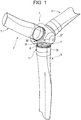
- a wind turbine is indicated generally at 2 in FIG. 1 .
- Wind turbine 2 includes a support hub 4 having attached thereto a first wind turbine blade 7, a second wind turbine blade 8, and a third wind turbine blade 9.
- Third wind turbine blade 9 includes a first end or root portion 11 and a second end or tip portion 12.
- first and second wind turbine blades 7 and 8 also include first end or root portions (not separately labeled) as well as second end or tip portions (also not separately labeled).
- End portion 11 includes an array of mechanical fasteners, indicated generally at 14, that extend through a corresponding plurality of openings, one of which is shown at 16 ( FIG. 3 ) provided on a blade receiving portion 18 of support hub 4.
- a blade replacement system a portion of which is indicated at 20, is provided within support hub 4.
- Blade replacement system 20 includes a first support member 25, a second support member 26, and a third support member 27.
- Support members 25-27 take the form of threaded rods (not separately labeled) that extend through openings 16 in blade receiving portion 18 and engage with threaded openings (not separately labeled) previously provided with fasteners 14 as shown in FIG. 2 .
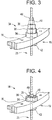
- a hydraulic jacking cylinder 34 illustrated in FIG. 3 , is guided over each support member 25-27.
- Hydraulic jacking cylinder 34 includes a base section 36 that rests on an inner surface (not separately labeled) of blade receiving portion 18 and a plurality of telescoping sections 38-40.
- Base section 36 and telescoping sections 38-40 include a central passage 42 that receives a corresponding one of support members 25-27.
- hydraulic jacking cylinder 34 is shown mounted over a free end (not separately labeled) of support member 25. Once in position, telescoping sections 38-40 are extended and a retaining nut 49 is threaded onto first support member 25. Once additional hydraulic jacking cylinders (not shown) are provided on first and second support members 26 and 27, retaining nuts 49 are removed from fasteners 14. At this point, telescoping sections 38-40 are shifted into base section 36 ( FIG. 4 ) separating third wind turbine blade 9 from support hub 4 a first distance. Once separated the first distance, one at a time, retaining nuts 49 are moved away from base section 36 and telescoping sections 38-40 are again extended in preparation for further separation of third wind turbine blade 9 from support hub 4.
- Blade replacement system 20 also includes a plurality of bracket members, one of which is indicated at 54 and a plurality of bracket elements, one of which is indicated at 57.
- bracket members 54 When separated the first distance, bracket members 54, are mounted to blade receiving portion 18 and bracket elements 57 are mounted to select ones of fasteners 14 on third wind turbine blade 9, as shown in FIG. 5 .
- Each bracket member 54 and bracket element 57 includes mounting structure, shown in the form of openings (not separately labeled).
- a number of cables 64, 65, and 66 are connected to corresponding ones of bracket members 54. Specifically, one end (not separately labeled) of each cable 64, 65, and 66 is mounted to a corresponding bracket member 54 which another, free end of each cable 64, 65, and 66 is allowed to fall toward ground.
- each cable 64, 65 and 66 may fall towards ground, a ship's deck, or a body of water depending upon the location of wind turbine 2.
- blade replacement system 20 further includes a plurality of cable climbing members 80, 81, and 82.
- Cable climbing members are connected to corresponding ones of cables 64, 65, and 66.
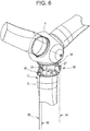
- Cable climbing members 80, 81, and 82 are controlled so as to climb from the free ends of each cable 64-66 toward bracket members 54, as shown in FIG. 6 .
- winch 80, 81, and 82 is similarly formed, a detailed description will follow to FIG. 7 in describing winch 80 with an understanding that cable climbing members 81 and 82 include corresponding structure.
- Winch 80 includes a housing 85 that supports a motor 88, a cable climbing portion 90 and a shackle 93.
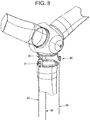
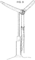
- Shackle 93 is connected to bracket element 57 through a coupler 96. Once all cable climbing members 80-82 are connected to corresponding bracket elements 57, telescoping sections 38-40 of hydraulic jacking cylinders 34 are further lowered transferring support of third wind turbine blade 9 from support members 25-27 to cable climbing members 80-82 as shown in FIG. 8 . At this point, support members 25-27 may be removed, and cable climbing members 80-82 shifted or climbed down cables 64-66 to lower third wind turbine blade 9 from support hub 4 as shown in FIG. 9 . The above steps may be revised to raise and install a new wind turbine blade.
- Root portion 11 of wind turbine blade 9 includes an inner surface 194.
- a plurality of hook members, one of which is indicated at 200, is attached to inner surface 194 of root portion 11.
- a tip rigging bracket 201 Prior to lowering wind turbine blade 9 to the ground, a tip rigging bracket 201 ( FIG. 15 ) is secured to adjacent to tip portion 12.
- a ground based tip rigging line or tether 202 may be secured or connected to tip rigging bracket 201.
- tether 202 allows personnel to shift tip portion 12 as wind turbine blade 9 is lowered to the ground.
- a plurality of first hoisting devices is secured between support hub 4 and wind turbine blade 9.
- Each of the plurality of first hoisting devices 204 may take the form of a chain hoist 206 having a first end 208 supported in support hub 4 and a second end 209 including a shackle 210 that is coupled to hook member 200.
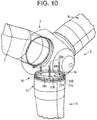
- One or more chains may extend between first and second ends 208 and 209. Once connected, wind turbine blade 9 may be disconnected from blade receiving portion 18. After freeing array of mechanical fasteners 14, wind turbine blade 9 may be lowered a first distance from wind turbine support hub 4 by plurality of first hoisting devices 204, as shown in FIG. 11 .
- a plurality of hook elements may be secured to array of mechanical fasteners 14, as shown in FIG. 12 .
- Each hook element 219 includes a base portion 221 and a hook eye portion 222.
- Base portion 221 may include one or more passages (not separately labeled) receptive to a corresponding one of array of mechanical fasteners 14.
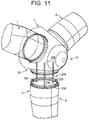
- a plurality of second hoisting devices one of which is indicated at 230, is connected between wind turbine support hub 4 and wind turbine blade 9, as shown in FIG. 13 .
- Each of the plurality of second hoisting devices 230 may take the form of a block and tackle 232 that may be lifted up to personnel in wind turbine support hub 4.
- Each block and tackle 232 includes a first end portion 234 fixedly supported within wind turbine support hub 4 and a second end portion 235 coupled to hook eye portion 222.
- a cable or rope 238 is threaded through pulleys (not separately labeled) carried by first and second end portions 234 and 235.
- Rope 238 includes a tag end 240 that extends to the ground.
- a handshake maneuver is performed after attaching the plurality of second hoisting devices 230.
- the plurality of first hoisting devices 204 are operated such that wind turbine blade 9 is supported by the plurality of second hoisting devices 230.
- the plurality of first hoisting devices 204 may be disconnected and removed, such as shown in FIG. 14 .
- the plurality of second hoisting devices 230 may be operated to lower wind turbine blade 9 toward the ground, as shown in FIG. 15 .
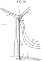
- tension may be applied to tether 202 to gradually move wind turbine blade 9 from a generally vertical orientation to a generally horizontal position. Wind turbine blade 9 may then be landed, as shown in FIG. 16 .
- Tension in tether 202 may be applied through ground based winches or by a small mobile crane.
- the exemplary embodiments describe a system for lowering and raising wind turbine blades without the need for ground-based cranes.
- the exemplary embodiments employ multiple hoisting devices that are used to lower the wind turbine blade to the ground without the need for large, ground based cranes. It should also be understood that the number and type of hoisting devices may vary. Further, it should be understood that a new blade can be raised and secured to the hub by reversing the process described above.
Landscapes
- Engineering & Computer Science (AREA)
- Life Sciences & Earth Sciences (AREA)
- Sustainable Development (AREA)
- Sustainable Energy (AREA)
- Chemical & Material Sciences (AREA)
- Combustion & Propulsion (AREA)
- Mechanical Engineering (AREA)
- General Engineering & Computer Science (AREA)
- Wind Motors (AREA)
Applications Claiming Priority (1)
| Application Number | Priority Date | Filing Date | Title |
|---|---|---|---|
| US14/697,054 US9745953B2 (en) | 2012-10-23 | 2015-04-27 | Method and system for replacing a single wind turbine blade |
Publications (2)
| Publication Number | Publication Date |
|---|---|
| EP3088732A1 true EP3088732A1 (fr) | 2016-11-02 |
| EP3088732B1 EP3088732B1 (fr) | 2020-02-05 |
Family
ID=55759565
Family Applications (1)
| Application Number | Title | Priority Date | Filing Date |
|---|---|---|---|
| EP16166071.7A Active EP3088732B1 (fr) | 2015-04-27 | 2016-04-19 | Procédé et système de remplacement d'une pale de turbine éolienne unique |
Country Status (6)
| Country | Link |
|---|---|
| EP (1) | EP3088732B1 (fr) |
| CN (2) | CN115419547A (fr) |
| BR (1) | BR102016008891B1 (fr) |
| CA (1) | CA2927197C (fr) |
| DK (1) | DK3088732T3 (fr) |
| ES (1) | ES2789025T3 (fr) |
Families Citing this family (6)
| Publication number | Priority date | Publication date | Assignee | Title |
|---|---|---|---|---|
| CN106744271B (zh) * | 2016-12-26 | 2019-02-12 | 北京金风科创风电设备有限公司 | 风力发电机叶片吊装工装、吊具及吊装方法和拆卸方法 |
| US10837425B2 (en) | 2017-09-11 | 2020-11-17 | Dalian University Of Technology | Hub mating mechanism applicable to single blade installation of offshore wind turbines |
| CN116928029A (zh) * | 2022-03-29 | 2023-10-24 | 福建金风科技有限公司 | 风力发电机组的叶片吊装方法和叶片吊装工装 |
| WO2024041683A1 (fr) * | 2022-08-22 | 2024-02-29 | Seilkonzept Gmbh & Co. Kg | Procédé de changement des pales d'une éolienne |
| CN115716624B (zh) * | 2022-10-20 | 2025-06-20 | 重庆海装风电工程技术有限公司 | 一种风力发电机更换叶片吊装系统 |
| EP4421311A1 (fr) * | 2023-02-23 | 2024-08-28 | Siemens Gamesa Renewable Energy A/S | Procédé d'abaissement et/ou de levage et procédé d'entretien d'une pale de rotor d'une éolienne |
Citations (3)
| Publication number | Priority date | Publication date | Assignee | Title |
|---|---|---|---|---|
| WO2009128708A2 (fr) * | 2008-04-16 | 2009-10-22 | Dutch Heavy Lift Concepts B.V. | Procédé et construction de levage permettant de lever et d’abaisser une pale d’éolienne |
| EP2369174A1 (fr) * | 2010-03-09 | 2011-09-28 | Lm Glasfiber A/S | Procédé pour le montage ou le démontage sans grue d'une pale d'éolienne |
| EP2725220A2 (fr) * | 2012-10-23 | 2014-04-30 | General Electric Company | Méthode et système pour échanger une seule pale d'éolienne |
Family Cites Families (5)
| Publication number | Priority date | Publication date | Assignee | Title |
|---|---|---|---|---|
| DE10303555B4 (de) * | 2003-01-29 | 2007-01-25 | Aloys Wobben | Verfahren zur kranlosen Montage eines Rotorblattes einer Windenergieanlage |
| CN201599142U (zh) * | 2009-07-21 | 2010-10-06 | 宁波中能风电科技有限公司 | 风叶安装法兰 |
| ES2564260T3 (es) * | 2010-11-18 | 2016-03-21 | Vestas Wind Systems A/S | Método para manipular sin grúa una pala de turbina eólica por medio de un buje de turbina |
| CN103597203B (zh) * | 2011-06-09 | 2016-10-12 | Pp能源有限责任公司 | 用于连接风力涡轮机的两个转子叶片段的升降装置 |
| US9394886B2 (en) * | 2013-03-07 | 2016-07-19 | General Electric Company | System and method for re-indexing a pitch bearing of a wind turbine |
-
2016
- 2016-04-14 CA CA2927197A patent/CA2927197C/fr active Active
- 2016-04-19 EP EP16166071.7A patent/EP3088732B1/fr active Active
- 2016-04-19 ES ES16166071T patent/ES2789025T3/es active Active
- 2016-04-19 DK DK16166071.7T patent/DK3088732T3/da active
- 2016-04-20 BR BR102016008891-7A patent/BR102016008891B1/pt active IP Right Grant
- 2016-04-27 CN CN202210971089.0A patent/CN115419547A/zh active Pending
- 2016-04-27 CN CN201610267550.9A patent/CN106089566A/zh active Pending
Patent Citations (3)
| Publication number | Priority date | Publication date | Assignee | Title |
|---|---|---|---|---|
| WO2009128708A2 (fr) * | 2008-04-16 | 2009-10-22 | Dutch Heavy Lift Concepts B.V. | Procédé et construction de levage permettant de lever et d’abaisser une pale d’éolienne |
| EP2369174A1 (fr) * | 2010-03-09 | 2011-09-28 | Lm Glasfiber A/S | Procédé pour le montage ou le démontage sans grue d'une pale d'éolienne |
| EP2725220A2 (fr) * | 2012-10-23 | 2014-04-30 | General Electric Company | Méthode et système pour échanger une seule pale d'éolienne |
Also Published As
| Publication number | Publication date |
|---|---|
| CN115419547A (zh) | 2022-12-02 |
| BR102016008891A2 (pt) | 2016-11-16 |
| BR102016008891B1 (pt) | 2022-05-17 |
| CA2927197C (fr) | 2019-04-09 |
| DK3088732T3 (da) | 2020-05-11 |
| EP3088732B1 (fr) | 2020-02-05 |
| CN106089566A (zh) | 2016-11-09 |
| ES2789025T3 (es) | 2020-10-23 |
| CA2927197A1 (fr) | 2016-10-27 |
Similar Documents
| Publication | Publication Date | Title |
|---|---|---|
| US9745953B2 (en) | Method and system for replacing a single wind turbine blade | |
| EP3088732B1 (fr) | Procédé et système de remplacement d'une pale de turbine éolienne unique | |
| EP3091222B1 (fr) | Système et procédé de remplacement d'un palier de pale d'éolienne | |
| EP3001029B1 (fr) | Systèmes de contrepoids pour une éolienne et procédés | |
| EP3191707B1 (fr) | Système et procédé pour retirer et/ou installer une pale de rotor d'une éolienne | |
| AU2007321076B2 (en) | Device and process for rapid disassembly of a rotor and a nacelle from the mast of a windmill, as well as a windmill that is equipped with such a device | |
| EP2725220B1 (fr) | Méthode et système pour échanger une seule pale d'éolienne | |
| EP2224126A2 (fr) | Procédé de manipulation d'une pale d'éolienne à position verticale | |
| EP3091223B1 (fr) | Système de suspension de tour supérieure pour une pale de rotor de turbine éolienne | |
| WO2011095167A2 (fr) | Procédé de levage et de descente d'une pale d'éolienne | |
| US11905143B2 (en) | Method for handling a wind turbine component with a control arrangement | |
| EP3559442B1 (fr) | Procédé et ensemble de manutention de pales d'éolienne | |
| CN105793560A (zh) | 用于维修风力涡轮机部件的固定装置 | |
| CN110088459A (zh) | 一种用于处理风轮机叶片的方法和组件 | |
| AU2024333286A1 (en) | A system for raising, positioning and lowering an offshore wind turbine blade and tower maintenance device | |
| JP2019074034A (ja) | 風力発電装置、風力発電装置の設置方法及び風力発電装置のメンテナンス方法 |
Legal Events
| Date | Code | Title | Description |
|---|---|---|---|
| PUAI | Public reference made under article 153(3) epc to a published international application that has entered the european phase |
Free format text: ORIGINAL CODE: 0009012 |
|
| AK | Designated contracting states |
Kind code of ref document: A1 Designated state(s): AL AT BE BG CH CY CZ DE DK EE ES FI FR GB GR HR HU IE IS IT LI LT LU LV MC MK MT NL NO PL PT RO RS SE SI SK SM TR |
|
| AX | Request for extension of the european patent |
Extension state: BA ME |
|
| 17P | Request for examination filed |
Effective date: 20170502 |
|
| RBV | Designated contracting states (corrected) |
Designated state(s): AL AT BE BG CH CY CZ DE DK EE ES FI FR GB GR HR HU IE IS IT LI LT LU LV MC MK MT NL NO PL PT RO RS SE SI SK SM TR |
|
| STAA | Information on the status of an ep patent application or granted ep patent |
Free format text: STATUS: REQUEST FOR EXAMINATION WAS MADE |
|
| GRAP | Despatch of communication of intention to grant a patent |
Free format text: ORIGINAL CODE: EPIDOSNIGR1 |
|
| STAA | Information on the status of an ep patent application or granted ep patent |
Free format text: STATUS: GRANT OF PATENT IS INTENDED |
|
| RIC1 | Information provided on ipc code assigned before grant |
Ipc: F03D 1/06 20060101AFI20190507BHEP |
|
| INTG | Intention to grant announced |
Effective date: 20190527 |
|
| GRAJ | Information related to disapproval of communication of intention to grant by the applicant or resumption of examination proceedings by the epo deleted |
Free format text: ORIGINAL CODE: EPIDOSDIGR1 |
|
| STAA | Information on the status of an ep patent application or granted ep patent |
Free format text: STATUS: REQUEST FOR EXAMINATION WAS MADE |
|
| GRAP | Despatch of communication of intention to grant a patent |
Free format text: ORIGINAL CODE: EPIDOSNIGR1 |
|
| STAA | Information on the status of an ep patent application or granted ep patent |
Free format text: STATUS: GRANT OF PATENT IS INTENDED |
|
| INTC | Intention to grant announced (deleted) | ||
| INTG | Intention to grant announced |
Effective date: 20190923 |
|
| GRAS | Grant fee paid |
Free format text: ORIGINAL CODE: EPIDOSNIGR3 |
|
| GRAA | (expected) grant |
Free format text: ORIGINAL CODE: 0009210 |
|
| STAA | Information on the status of an ep patent application or granted ep patent |
Free format text: STATUS: THE PATENT HAS BEEN GRANTED |
|
| AK | Designated contracting states |
Kind code of ref document: B1 Designated state(s): AL AT BE BG CH CY CZ DE DK EE ES FI FR GB GR HR HU IE IS IT LI LT LU LV MC MK MT NL NO PL PT RO RS SE SI SK SM TR |
|
| REG | Reference to a national code |
Ref country code: GB Ref legal event code: FG4D |
|
| REG | Reference to a national code |
Ref country code: AT Ref legal event code: REF Ref document number: 1230080 Country of ref document: AT Kind code of ref document: T Effective date: 20200215 |
|
| REG | Reference to a national code |
Ref country code: DE Ref legal event code: R096 Ref document number: 602016029021 Country of ref document: DE |
|
| REG | Reference to a national code |
Ref country code: IE Ref legal event code: FG4D |
|
| REG | Reference to a national code |
Ref country code: CH Ref legal event code: EP |
|
| REG | Reference to a national code |
Ref country code: DK Ref legal event code: T3 Effective date: 20200504 |
|
| REG | Reference to a national code |
Ref country code: NL Ref legal event code: MP Effective date: 20200205 |
|
| PG25 | Lapsed in a contracting state [announced via postgrant information from national office to epo] |
Ref country code: NO Free format text: LAPSE BECAUSE OF FAILURE TO SUBMIT A TRANSLATION OF THE DESCRIPTION OR TO PAY THE FEE WITHIN THE PRESCRIBED TIME-LIMIT Effective date: 20200505 Ref country code: FI Free format text: LAPSE BECAUSE OF FAILURE TO SUBMIT A TRANSLATION OF THE DESCRIPTION OR TO PAY THE FEE WITHIN THE PRESCRIBED TIME-LIMIT Effective date: 20200205 Ref country code: PT Free format text: LAPSE BECAUSE OF FAILURE TO SUBMIT A TRANSLATION OF THE DESCRIPTION OR TO PAY THE FEE WITHIN THE PRESCRIBED TIME-LIMIT Effective date: 20200628 Ref country code: RS Free format text: LAPSE BECAUSE OF FAILURE TO SUBMIT A TRANSLATION OF THE DESCRIPTION OR TO PAY THE FEE WITHIN THE PRESCRIBED TIME-LIMIT Effective date: 20200205 |
|
| REG | Reference to a national code |
Ref country code: LT Ref legal event code: MG4D |
|
| PG25 | Lapsed in a contracting state [announced via postgrant information from national office to epo] |
Ref country code: SE Free format text: LAPSE BECAUSE OF FAILURE TO SUBMIT A TRANSLATION OF THE DESCRIPTION OR TO PAY THE FEE WITHIN THE PRESCRIBED TIME-LIMIT Effective date: 20200205 Ref country code: LV Free format text: LAPSE BECAUSE OF FAILURE TO SUBMIT A TRANSLATION OF THE DESCRIPTION OR TO PAY THE FEE WITHIN THE PRESCRIBED TIME-LIMIT Effective date: 20200205 Ref country code: GR Free format text: LAPSE BECAUSE OF FAILURE TO SUBMIT A TRANSLATION OF THE DESCRIPTION OR TO PAY THE FEE WITHIN THE PRESCRIBED TIME-LIMIT Effective date: 20200506 Ref country code: HR Free format text: LAPSE BECAUSE OF FAILURE TO SUBMIT A TRANSLATION OF THE DESCRIPTION OR TO PAY THE FEE WITHIN THE PRESCRIBED TIME-LIMIT Effective date: 20200205 Ref country code: IS Free format text: LAPSE BECAUSE OF FAILURE TO SUBMIT A TRANSLATION OF THE DESCRIPTION OR TO PAY THE FEE WITHIN THE PRESCRIBED TIME-LIMIT Effective date: 20200605 Ref country code: BG Free format text: LAPSE BECAUSE OF FAILURE TO SUBMIT A TRANSLATION OF THE DESCRIPTION OR TO PAY THE FEE WITHIN THE PRESCRIBED TIME-LIMIT Effective date: 20200505 |
|
| PG25 | Lapsed in a contracting state [announced via postgrant information from national office to epo] |
Ref country code: NL Free format text: LAPSE BECAUSE OF FAILURE TO SUBMIT A TRANSLATION OF THE DESCRIPTION OR TO PAY THE FEE WITHIN THE PRESCRIBED TIME-LIMIT Effective date: 20200205 |
|
| REG | Reference to a national code |
Ref country code: ES Ref legal event code: FG2A Ref document number: 2789025 Country of ref document: ES Kind code of ref document: T3 Effective date: 20201023 |
|
| PG25 | Lapsed in a contracting state [announced via postgrant information from national office to epo] |
Ref country code: CZ Free format text: LAPSE BECAUSE OF FAILURE TO SUBMIT A TRANSLATION OF THE DESCRIPTION OR TO PAY THE FEE WITHIN THE PRESCRIBED TIME-LIMIT Effective date: 20200205 Ref country code: RO Free format text: LAPSE BECAUSE OF FAILURE TO SUBMIT A TRANSLATION OF THE DESCRIPTION OR TO PAY THE FEE WITHIN THE PRESCRIBED TIME-LIMIT Effective date: 20200205 Ref country code: LT Free format text: LAPSE BECAUSE OF FAILURE TO SUBMIT A TRANSLATION OF THE DESCRIPTION OR TO PAY THE FEE WITHIN THE PRESCRIBED TIME-LIMIT Effective date: 20200205 Ref country code: SM Free format text: LAPSE BECAUSE OF FAILURE TO SUBMIT A TRANSLATION OF THE DESCRIPTION OR TO PAY THE FEE WITHIN THE PRESCRIBED TIME-LIMIT Effective date: 20200205 Ref country code: EE Free format text: LAPSE BECAUSE OF FAILURE TO SUBMIT A TRANSLATION OF THE DESCRIPTION OR TO PAY THE FEE WITHIN THE PRESCRIBED TIME-LIMIT Effective date: 20200205 Ref country code: SK Free format text: LAPSE BECAUSE OF FAILURE TO SUBMIT A TRANSLATION OF THE DESCRIPTION OR TO PAY THE FEE WITHIN THE PRESCRIBED TIME-LIMIT Effective date: 20200205 |
|
| REG | Reference to a national code |
Ref country code: DE Ref legal event code: R097 Ref document number: 602016029021 Country of ref document: DE |
|
| REG | Reference to a national code |
Ref country code: AT Ref legal event code: MK05 Ref document number: 1230080 Country of ref document: AT Kind code of ref document: T Effective date: 20200205 |
|
| PG25 | Lapsed in a contracting state [announced via postgrant information from national office to epo] |
Ref country code: MC Free format text: LAPSE BECAUSE OF FAILURE TO SUBMIT A TRANSLATION OF THE DESCRIPTION OR TO PAY THE FEE WITHIN THE PRESCRIBED TIME-LIMIT Effective date: 20200205 |
|
| REG | Reference to a national code |
Ref country code: CH Ref legal event code: PL |
|
| PLBE | No opposition filed within time limit |
Free format text: ORIGINAL CODE: 0009261 |
|
| STAA | Information on the status of an ep patent application or granted ep patent |
Free format text: STATUS: NO OPPOSITION FILED WITHIN TIME LIMIT |
|
| 26N | No opposition filed |
Effective date: 20201106 |
|
| PG25 | Lapsed in a contracting state [announced via postgrant information from national office to epo] |
Ref country code: AT Free format text: LAPSE BECAUSE OF FAILURE TO SUBMIT A TRANSLATION OF THE DESCRIPTION OR TO PAY THE FEE WITHIN THE PRESCRIBED TIME-LIMIT Effective date: 20200205 Ref country code: LU Free format text: LAPSE BECAUSE OF NON-PAYMENT OF DUE FEES Effective date: 20200419 Ref country code: IT Free format text: LAPSE BECAUSE OF FAILURE TO SUBMIT A TRANSLATION OF THE DESCRIPTION OR TO PAY THE FEE WITHIN THE PRESCRIBED TIME-LIMIT Effective date: 20200205 Ref country code: FR Free format text: LAPSE BECAUSE OF NON-PAYMENT OF DUE FEES Effective date: 20200430 Ref country code: LI Free format text: LAPSE BECAUSE OF NON-PAYMENT OF DUE FEES Effective date: 20200430 Ref country code: CH Free format text: LAPSE BECAUSE OF NON-PAYMENT OF DUE FEES Effective date: 20200430 |
|
| REG | Reference to a national code |
Ref country code: BE Ref legal event code: MM Effective date: 20200430 |
|
| PG25 | Lapsed in a contracting state [announced via postgrant information from national office to epo] |
Ref country code: SI Free format text: LAPSE BECAUSE OF FAILURE TO SUBMIT A TRANSLATION OF THE DESCRIPTION OR TO PAY THE FEE WITHIN THE PRESCRIBED TIME-LIMIT Effective date: 20200205 Ref country code: BE Free format text: LAPSE BECAUSE OF NON-PAYMENT OF DUE FEES Effective date: 20200430 Ref country code: PL Free format text: LAPSE BECAUSE OF FAILURE TO SUBMIT A TRANSLATION OF THE DESCRIPTION OR TO PAY THE FEE WITHIN THE PRESCRIBED TIME-LIMIT Effective date: 20200205 |
|
| GBPC | Gb: european patent ceased through non-payment of renewal fee |
Effective date: 20200505 |
|
| PG25 | Lapsed in a contracting state [announced via postgrant information from national office to epo] |
Ref country code: GB Free format text: LAPSE BECAUSE OF NON-PAYMENT OF DUE FEES Effective date: 20200505 Ref country code: IE Free format text: LAPSE BECAUSE OF NON-PAYMENT OF DUE FEES Effective date: 20200419 |
|
| PG25 | Lapsed in a contracting state [announced via postgrant information from national office to epo] |
Ref country code: TR Free format text: LAPSE BECAUSE OF FAILURE TO SUBMIT A TRANSLATION OF THE DESCRIPTION OR TO PAY THE FEE WITHIN THE PRESCRIBED TIME-LIMIT Effective date: 20200205 Ref country code: MT Free format text: LAPSE BECAUSE OF FAILURE TO SUBMIT A TRANSLATION OF THE DESCRIPTION OR TO PAY THE FEE WITHIN THE PRESCRIBED TIME-LIMIT Effective date: 20200205 Ref country code: CY Free format text: LAPSE BECAUSE OF FAILURE TO SUBMIT A TRANSLATION OF THE DESCRIPTION OR TO PAY THE FEE WITHIN THE PRESCRIBED TIME-LIMIT Effective date: 20200205 |
|
| PG25 | Lapsed in a contracting state [announced via postgrant information from national office to epo] |
Ref country code: MK Free format text: LAPSE BECAUSE OF FAILURE TO SUBMIT A TRANSLATION OF THE DESCRIPTION OR TO PAY THE FEE WITHIN THE PRESCRIBED TIME-LIMIT Effective date: 20200205 Ref country code: AL Free format text: LAPSE BECAUSE OF FAILURE TO SUBMIT A TRANSLATION OF THE DESCRIPTION OR TO PAY THE FEE WITHIN THE PRESCRIBED TIME-LIMIT Effective date: 20200205 |
|
| P01 | Opt-out of the competence of the unified patent court (upc) registered |
Effective date: 20230530 |
|
| REG | Reference to a national code |
Ref country code: DE Ref legal event code: R082 Ref document number: 602016029021 Country of ref document: DE Representative=s name: ZIMMERMANN & PARTNER PATENTANWAELTE MBB, DE Ref country code: DE Ref legal event code: R082 Ref document number: 602016029021 Country of ref document: DE Ref country code: DE Ref legal event code: R081 Ref document number: 602016029021 Country of ref document: DE Owner name: GENERAL ELECTRIC RENOVABLES ESPANA, S.L., ES Free format text: FORMER OWNER: GENERAL ELECTRIC COMPANY, SCHENECTADY, NY, US |
|
| REG | Reference to a national code |
Ref country code: DE Ref legal event code: R082 Ref document number: 602016029021 Country of ref document: DE Representative=s name: ZIMMERMANN & PARTNER PATENTANWAELTE MBB, DE |
|
| REG | Reference to a national code |
Ref country code: ES Ref legal event code: PC2A Owner name: GENERAL ELECTRIC RENOVABLES ESPANA S.L. Effective date: 20240809 |
|
| PGFP | Annual fee paid to national office [announced via postgrant information from national office to epo] |
Ref country code: DE Payment date: 20250319 Year of fee payment: 10 |
|
| PGFP | Annual fee paid to national office [announced via postgrant information from national office to epo] |
Ref country code: ES Payment date: 20250502 Year of fee payment: 10 |
|
| PGFP | Annual fee paid to national office [announced via postgrant information from national office to epo] |
Ref country code: DK Payment date: 20260319 Year of fee payment: 11 |