EP3088741B1 - Système de contrôle amélioré pour une turbopompe - Google Patents
Système de contrôle amélioré pour une turbopompe Download PDFInfo
- Publication number
- EP3088741B1 EP3088741B1 EP16167333.0A EP16167333A EP3088741B1 EP 3088741 B1 EP3088741 B1 EP 3088741B1 EP 16167333 A EP16167333 A EP 16167333A EP 3088741 B1 EP3088741 B1 EP 3088741B1
- Authority
- EP
- European Patent Office
- Prior art keywords
- turbopump
- magnetic
- torque generator
- driving shaft
- magnetic torque
- Prior art date
- Legal status (The legal status is an assumption and is not a legal conclusion. Google has not performed a legal analysis and makes no representation as to the accuracy of the status listed.)
- Active
Links
Images
Classifications
-
- F—MECHANICAL ENGINEERING; LIGHTING; HEATING; WEAPONS; BLASTING
- F04—POSITIVE - DISPLACEMENT MACHINES FOR LIQUIDS; PUMPS FOR LIQUIDS OR ELASTIC FLUIDS
- F04D—NON-POSITIVE-DISPLACEMENT PUMPS
- F04D13/00—Pumping installations or systems
- F04D13/02—Units comprising pumps and their driving means
- F04D13/04—Units comprising pumps and their driving means the pump being fluid driven
-
- F—MECHANICAL ENGINEERING; LIGHTING; HEATING; WEAPONS; BLASTING
- F04—POSITIVE - DISPLACEMENT MACHINES FOR LIQUIDS; PUMPS FOR LIQUIDS OR ELASTIC FLUIDS
- F04D—NON-POSITIVE-DISPLACEMENT PUMPS
- F04D13/00—Pumping installations or systems
- F04D13/02—Units comprising pumps and their driving means
- F04D13/06—Units comprising pumps and their driving means the pump being electrically driven
- F04D13/0606—Canned motor pumps
-
- F—MECHANICAL ENGINEERING; LIGHTING; HEATING; WEAPONS; BLASTING
- F04—POSITIVE - DISPLACEMENT MACHINES FOR LIQUIDS; PUMPS FOR LIQUIDS OR ELASTIC FLUIDS
- F04D—NON-POSITIVE-DISPLACEMENT PUMPS
- F04D15/00—Control, e.g. regulation, of pumps, pumping installations or systems
- F04D15/0066—Control, e.g. regulation, of pumps, pumping installations or systems by changing the speed, e.g. of the driving engine
Definitions
- the present invention relates to the field of turbopumps, used in particular for spacecraft.
- Turbopumps are commonly controlled either by controlling the flow at the inlet of the turbopump, for example by restricting the flow downstream from the turbopump, or by controlling the speed of rotation of a drive shaft of the turbopump. , for example by controlling the energy supplied to this drive shaft, commonly by a turbine.
- Such control is suitable within the nominal operating range of a turbopump, once started and in steady state, and having sufficient energy to allow a significant gain between an actuator and the parameter to be controlled.
- the document CA 2394819 thus presents an example of a turbopump.
- turbopumps tend either to converge towards the nominal regime due to energy contributions resulting from the thermodynamic cycle taking place within the turbopump, or to remain in standby mode in the absence of input d additional energy.
- the turbopump further comprises a control unit, configured so as to control the magnetic torque generator in order to selectively apply a driving or resistant torque to the drive shaft, for example according to the state of the turbopump or d '' a command applied by control software.
- the magnetic torque generator comprises for example magnetic poles arranged on the stator and on the rotor of the turbopump, so as to form a synchronous machine.
- the magnetic torque generator comprises for example magnetic poles arranged on the stator, and a material ferromagnetic arranged on the rotor, adapted to allow the generation of an induced field, so as to form an asynchronous machine.
- the magnetic torque generator is for example configured so as to generate a radial and / or axial flux.
- the magnetic torque generator can be configured so as to establish a radial magnetic field for holding the drive shaft and thus perform a bearing function, and / or configured so as to form a stop limiting the axial movement of the shaft and thus achieve a balancing function.
- Said magnetic holding field is for example a repelling field, configured to hold the drive shaft spaced from the stator of the turbopump.
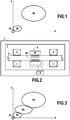
- the figure 2 schematically presents a turbopump 1 according to one aspect of the invention.
- the turbopump 1 shown comprises a fixed assembly defining a stator, and a mobile assembly defining a rotor.
- the rotor of the turbopump 1 comprises for example a drive shaft 2, typically driven in rotation by a turbine, not shown in this figure, or any other suitable rotary drive member.
- the drive shaft 2 performs the rotational drive of the rotor of the turbopump 1, and thus ensures its operation.
- the fixed assembly comprises for example a casing 3 of the turbopump 1, as well as bearings 4 making it possible to mount the drive shaft 2 rotating relative to the casing 3.
- the regimes R2 and R3, corresponding to the stable operating regimes of the turbopump, are disjoint, that is to say that a continuous transition from the regime R2 to the regime R3 (or vice versa) is only possible by passing through an unstable intermediate regime, and that operation outside of these two regimes R2 or R3 will naturally tend to bring the turbopump back to one or the other of these stable regimes.
- the turbopump 1 further comprises a magnetic torque generator 5, configured so as to selectively apply a torque to the drive shaft 2.
- the magnetic torque generator 5 comprises a fixed part 51, for example magnetic poles arranged on the stator of the turbopump 1, and a mobile part 52 mounted on the drive shaft 2, for example magnetic poles or portions comprising a ferromagnetic material.
- the magnetic torque generator 5 is associated with a control 6, configured so as to control the torque applied by the magnetic torque generator 5 on the drive shaft 2.
- the control 6 typically includes a shaft position sensor drive 2, to control the torque applied by the magnetic torque generator 5 depending in particular on the position of the drive shaft 2.
- the magnetic torque generator 5 is arranged between two bearings 4 of the drive shaft 2. Such positioning is not limiting; the magnetic torque generator 5 can also be arranged at one end of the drive shaft 2, or according to any other suitable configuration.
- the magnetic poles of the fixed part 51 and of the movable part 52 can for example be distributed in several distinct portions of the drive shaft 2.
- the magnetic torque generator 5 is of radial flux. Another embodiment not shown is the axial flow torque generator.
- the magnetic torque generator 5 has an operation similar to that of a synchronous machine.
- the fixed part 51 of the magnetic torque generator 5 comprises magnetic poles
- the movable part 52 of the magnetic torque generator 5 comprises portions comprising a ferromagnetic material
- the magnetic torque generator 5 has an operation similar to that of an asynchronous machine.
- controlling the phase and the current intensity of the magnetic torque generator 5 makes it possible to control the rotating field generated, and thus to control the torque produced by the magnetic torque generator 5 on l drive shaft 2.
- the torque thus produced by the magnetic torque generator 5 on the drive shaft 2 can be finely controlled, thus allowing control of the resulting torque on the drive shaft 2.
- the magnetic torque generator 5 thus makes it possible to generate a torque on the drive shaft 2 of the turbopump, and therefore makes it possible to modify its operating modes.
- the magnetic torque generator 5 produces a torque which may be a driving torque or a resisting torque on the drive shaft 2.
- the magnetic torque generator 5 makes it possible to obtain an additional stable speed of the turbopump between the nominal speed R3 and the waiting speed R2 already described with reference to the figure 1 .
- Such a stable R4 speed is obtained by applying a motor or resistant torque to the drive shaft 2 of the turbopump 1, when the latter is in standby mode R2 or in nominal speed R3.
- the magnetic torque generator 5 can apply a driving torque to the drive shaft 2, in order to increase the speed of rotation and the resulting torque on the drive shaft. drive 2 of the turbopump 1, and therefore achieve a ramp-up of the turbopump 1.
- the magnetic torque generator 5 can apply a resistive torque to the drive shaft 2, in order to reduce the speed of rotation and the resulting torque on the drive shaft 2 of the turbopump 1, and therefore achieve a drop in speed of the turbopump 1.
- the magnetic torque generator 5 allows, via the application of a motor or resisting torque on the drive shaft 2, to reach stable operating points between the standby speed R2 and the nominal speed R3, checking the resulting torque on the drive shaft 2.
- An additional stability domain is thus obtained for the turbomachine, identified by the region R4 on the figure 3 .
- the application of a motor or resistant torque to the drive shaft 2 also makes it possible to improve the transition between the nominal speed R3 and the waiting speed R2, either by initiating the speed increase to change from the speed standby R2 at nominal speed R3 and also to improve the start-up of the turbopump to pass from a stopped state R1 to the standby speed R2, either by dissipating the energy commonly supplied by the turbine and thus achieving a decrease from nominal speed R3 to standby speed R2.
- the magnetic torque generator 5 makes it possible to carry out a drive of the drive shaft at very low and controlled speeds of rotation, which makes it possible to carry out a circulation of cryogenic propellants in the turbopump in order to achieve its setting in cold, that is to say its gradual cooling from room temperature to cryogenic operating temperatures.
- Such controlled circulation of propellants makes it possible to reduce the consumption of propellants compared to conventional methods of cooling.
- the precise control of the starting torque makes it possible to specify the design of the starting sequences of the turbopump, in particular by overcoming inaccuracies due in particular to the low speed regimes of conventional turbopumps whose properties are not known in a manner sufficiently precise in the design phases.
- the magnetic torque generator 5 also makes it possible to perform a function of holding the drive shaft 2, by forming an axial stop or a bearing for the drive shaft 2. To do this, the magnetic torque generator 5 is configured so as to generate a repulsion force between the stator and the rotor, or more precisely between the fixed part 51 and the mobile part 52 of the magnetic torque generator 5.
- a field repellant is typically produced by generating a stator flux opposite to the rotor flux, for example by generating a rotating field at a very high speed, or by producing a passive configuration in which the north / south poles of the rotor are permanently in phase with the poles South / North (respectively) of the stator.
- the repulsion force thus generated makes it possible to avoid contact between the drive shaft 2 and the stator, which is advantageous both in terms of efficiency and of wear.
- the magnetic torque generator 5 is a reversible system, and that the rotation of the drive shaft 2 can thus be exploited in order to generate electricity as soon as an associated electrical converter is also reversible , for example when the turbopump 1 is in a stable speed such as the nominal speed R3, for which it is not necessary to apply a torque via the magnetic torque generator 5.
- the different functions performed by the magnetic torque generator 5 can be grouped. One can for example depending on the speed of the turbopump 1, perform a torque application function on the drive shaft 2 or energy recovery to generate electricity.
Landscapes
- Engineering & Computer Science (AREA)
- Mechanical Engineering (AREA)
- General Engineering & Computer Science (AREA)
- Structures Of Non-Positive Displacement Pumps (AREA)
- Details And Applications Of Rotary Liquid Pumps (AREA)
Description
- La présente invention concerne le domaine des turbopompes, utilisées notamment pour les engins spatiaux.
- Les turbopompes utilisées pour les moteurs d'engins spatiaux doivent communément fonctionner sur des domaines étendus.
- Le contrôle des turbopompes est communément réalisé soit via le pilotage du débit en entrée de la turbopompe, par exemple en restreignant le débit en aval de la turbopompe, soit via le pilotage de la vitesse de rotation d'un arbre d'entrainement de la turbopompe, par exemple en contrôlant l'énergie apportée à cet arbre d'entrainement, communément par une turbine.
- Un tel contrôle est adapté dans la plage nominale de fonctionnement d'une turbopompe, une fois démarrée et en régime stable, et disposant de suffisamment d'énergie pour permettre un gain important entre un actionneur et le paramètre à contrôler.
- Les turbopompes présentent en effet plusieurs régimes stables, à savoir :
- R1 : A l'arrêt,
- R2 : En attente, dans lequel la turbopompe est en fonctionnement mais sa vitesse de rotation et le couple appliqué sont minimisés,
- R3 : En régime nominal, à vitesse de rotation et couple élevés.
- Ces régimes R1, R2 et R3 sont indiqués schématiquement sur la
figure 1 , en fonction de la poussée délivrée (axe horizontal X) et de la vitesse de rotation (axe vertical Y). - Le document
CA 2394819 présente ainsi un exemple de turbopompe. - Les contrôles conventionnels ne sont cependant pas adaptés pour permettre un fonctionnement en régime stable entre le régime d'attente R2, et le régime nominal R3 de la turbopompe. En effet, les turbopompes ont tendance soit à converger vers le régime nominal du fait d'apports d'énergie résultant du cycle thermodynamique ayant lieu au sein de la turbopompe, soit à demeurer en régime d'attente en l'absence d'apport d'énergie additionnelle.
- On cherche ainsi à obtenir un fonctionnement amélioré entre le régime d'attente et le régime nominal.
- La présente invention vise à répondre au moins en partie à ces problématiques, et propose ainsi une turbopompe comprenant
- un ensemble fixe définissant un stator de la turbopompe, et
- un ensemble mobile définissant un rotor de la turbopompe, comprenant un arbre d'entrainement, et un organe d'entrainement adapté pour entrainer l'arbre d'entrainement,
- La turbopompe comprend en outre une unité de commande, configurée de manière à piloter le générateur magnétique de couple afin d'appliquer sélectivement un couple moteur ou résistant sur l'arbre d'entrainement par exemple en fonction de l'état de la turbopompe ou d'une commande appliquée par un logiciel de commande.
- Le générateur magnétique de couple comprend par exemple des pôles magnétiques disposés sur le stator et sur le rotor de la turbopompe, de manière à former une machine synchrone.
- En variante, le générateur magnétique de couple comprend par exemple des pôles magnétiques disposés sur le stator, et un matériau ferromagnétique disposé sur le rotor, adapté pour permettre la génération d'un champ induit, de manière à former une machine asynchrone.
- Le générateur magnétique de couple est par exemple configuré de manière à générer un flux radial et/ou axial.
- Le générateur magnétique de couple peut être configuré de manière à établir un champ magnétique de maintien radial de l'arbre d'entrainement et réaliser ainsi une fonction palier, et/ou configuré de manière à former une butée limitant le déplacement axial de l'arbre d'entrainement et réaliser ainsi une fonction d'équilibrage.
Ledit champ magnétique de maintien est par exemple un champ répulsif, configuré pour maintenir l'arbre d'entrainement espacé du stator de la turbopompe. - D'autres caractéristiques, buts et avantages de l'invention ressortiront de la description qui suit, qui est purement illustrative et non limitative, et qui doit être lue en regard des figures annexées, sur lesquelles :
- La
figure 1 présentée précédemment illustre les modes de fonctionnement conventionnels d'une turbopompe, - La
figure 2 présente schématiquement un système selon un aspect de l'invention, - La
figure 3 illustre les modes de fonctionnement obtenus au moyen d'un tel système. - Sur l'ensemble des figures, les éléments en commun sont repérés par des références numériques identiques.
- La
figure 2 présente schématiquement une turbopompe 1 selon un aspect de l'invention. - La turbopompe 1 représentée comprend un ensemble fixe définissant un stator, et un ensemble mobile définissant un rotor.
- Le rotor de la turbopompe 1 comprend par exemple un arbre d'entrainement 2, typiquement entrainé en rotation par une turbine, non représentée sur cette figure, ou tout autre organe d'entrainement en rotation approprié.
- L'arbre d'entrainement 2 réalise l'entrainement en rotation du rotor de la turbopompe 1, et assure ainsi son fonctionnement.
- L'ensemble fixe comprend par exemple un carter 3 de la turbopompe 1, ainsi que des paliers 4 permettant de monter l'arbre d'entrainement 2 tournant par rapport au carter 3.
- Comme indiqué précédemment en référence à la
figure 1 , la turbopompe 1 présente plusieurs régimes stables, à savoir : - R1 : A l'arrêt,
- R2 : En attente, dans lequel la turbopompe est en fonctionnement mais sa vitesse de rotation et le couple appliqué sont minimisés,
- R3 : En régime nominal, à vitesse de rotation et couple élevés.
- Ces régimes R1, R2 et R3 sont indiqués schématiquement sur la
figure 1 , en fonction de la poussée délivrée (axe horizontal X) et de la vitesse de rotation (axe vertical Y). - Les régimes R2 et R3, correspondant aux régimes stables de fonctionnement de la turbopompe sont disjoints, c'est-à-dire qu'une transition continue du régime R2 vers le régime R3 (ou inversement) n'est possible qu'en passant par un régime intermédiaire instable, et qu'un fonctionnement hors de ces deux régimes R2 ou R3 va tendre naturellement à ramener la turbopompe vers l'un ou l'autre de ces régimes stables.
- La turbopompe 1 comprend de plus un générateur magnétique de couple 5, configuré de manière à sélectivement appliquer un couple sur l'arbre d'entrainement 2.
Le générateur magnétique de couple 5 comprend une partie fixe 51, par exemple des pôles magnétiques disposés sur le stator de la turbopompe 1, et une partie mobile 52 montée sur l'arbre d'entrainement 2, par exemple des pôles magnétiques ou des portions comprenant un matériau ferromagnétique. - Le générateur magnétique de couple 5 est associé à une commande 6, configurée de manière à piloter le couple appliqué par le générateur magnétique de couple 5 sur l'arbre d'entrainement 2. La commande 6 comprend typiquement un capteur de position de l'arbre d'entrainement 2, afin de piloter le couple appliqué par le générateur magnétique de couple 5 en fonction notamment de la position de l'arbre d'entrainement 2.
- Dans le mode de réalisation représenté sur la
figure 2 , le générateur magnétique de couple 5 est disposé entre deux paliers 4 de l'arbre d'entrainement 2. Un tel positionnement n'est pas limitatif ; le générateur magnétique de couple 5 peut également être disposé à une extrémité de l'arbre d'entrainement 2, ou selon toute autre configuration adaptée. Les pôles magnétiques de la partie fixe 51 et de la partie mobile 52 peuvent par exemple être répartis selon plusieurs portions distinctes de l'arbre d'entrainement 2. - Dans le mode de réalisation représenté sur la
figure 2 , le générateur magnétique de couple 5 est à flux radial. Un autre mode de réalisation non représenté est le générateur de couple à flux axial. - On distingue deux modes de fonctionnement du générateur magnétique de couple 5, selon la nature de ses parties fixe 51 et mobile 52.
- Dans le cas où la partie fixe 51 et la partie mobile sont des pôles magnétiques, le générateur magnétique de couple 5 présente un fonctionnement similaire à celui d'une machine synchrone.
Dans le cas où la partie fixe 51 du générateur magnétique de couple 5 comprend des pôles magnétiques, alors que la partie mobile 52 du générateur magnétique de couple 5 comprend des portions comprenant un matériau ferromagnétique, le générateur magnétique de couple 5 présente un fonctionnement similaire à celui d'une machine asynchrone. - Quel que soit le mode de fonctionnement, le contrôle de la phase et de l'intensité du courant du générateur magnétique de couple 5 permet de contrôler le champ tournant généré, et ainsi de contrôler le couple produit par le générateur magnétique de couple 5 sur l'arbre d'entrainement 2.
Le couple ainsi produit par le générateur magnétique de couple 5 sur l'arbre d'entrainement 2 peut être piloté de manière fine, permettant ainsi une maîtrise du couple résultant sur l'arbre d'entrainement 2. - Le générateur magnétique de couple 5 permet ainsi de générer un couple sur l'arbre d'entrainement 2 de la turbopompe, et permet donc de modifier ses modes de fonctionnement.
- Plus précisément, en fonction du champ tournant généré et du couple produit, ainsi que de la vitesse de rotation de l'arbre d'entrainement 2, le générateur magnétique de couple 5 produit un couple pouvant être un couple moteur ou un couple résistant sur l'arbre d'entrainement 2.
- Ainsi, le générateur magnétique de couple 5 permet d'obtenir un régime stable additionnel de la turbopompe entre le régime nominal R3 et le régime d'attente R2 déjà décrits en référence à la
figure 1 . - On représente sur la
figure 3 les modes de fonctionnement obtenus pour la turbopompe 1 au moyen d'un tel système, en indiquant la poussée selon l'horizontal X et la vitesse de rotation en tours par minute selon l'axe vertical Y.
Comme déjà décrit en référence à lafigure 1 , on représente sur lafigure 3 plusieurs régimes stables, à savoir : - R1 : A l'arrêt,
- R2 : En attente, dans lequel la turbopompe est en fonctionnement mais sa vitesse de rotation et le couple appliqué sont minimisés,
- R3 : En régime nominal, à vitesse de rotation et couple élevés.
- Un tel régime R4 stable est obtenu en appliquant un couple moteur ou résistant sur l'arbre d'entrainement 2 de la turbopompe 1, lorsque cette dernière est en régime d'attente R2 ou en régime nominal R3.
- Lorsque la turbopompe 1 est en régime d'attente R2, le générateur magnétique de couple 5 peut appliquer un couple moteur sur l'arbre d'entrainement 2, afin d'augmenter la vitesse de rotation et le couple résultant sur l'arbre d'entrainement 2 de la turbopompe 1, et donc réaliser une montée en régime de la turbopompe 1.
A l'inverse, lorsque la turbopompe 1 est en régime nominal R3, le générateur magnétique de couple 5 peut appliquer un couple résistant sur l'arbre d'entrainement 2, afin d'en diminuer la vitesse de rotation et le couple résultant sur l'arbre d'entrainement 2 de la turbopompe 1, et donc réaliser une baisse en régime de la turbopompe 1. - Ainsi, le générateur magnétique de couple 5 permet, via l'application d'un couple moteur ou résistant sur l'arbre d'entrainement 2, d'atteindre des points de fonctionnement stables entre le régime d'attente R2 et le régime nominal R3, en contrôlant le couple résultant sur l'arbre d'entraînement 2.
On obtient ainsi un domaine de stabilité additionnel pour la turbomachine, repéré par la région R4 sur lafigure 3 . - L'application d'un couple moteur ou résistant sur l'arbre d'entrainement 2 permet de plus d'améliorer la transition entre le régime nominal R3 et le régime d'attente R2, soit en amorçant la montée en régime pour passer du régime d'attente R2 au régime nominal R3 et également pour améliorer le démarrage de la turbopompe pour passer d'un état d'arrêt R1 au régime d'attente R2, soit en dissipant l'énergie apportée communément par la turbine et ainsi en réalisant une baisse du régime nominal R3 vers le régime d'attente R2.
- Par ailleurs, le générateur magnétique de couple 5 permet de réaliser un entraînement de l'arbre d'entrainement à des vitesses de rotation très faibles et contrôlées, ce qui permet de réaliser une circulation d'ergols cryogéniques dans la turbopompe afin de réaliser sa mise en froid, c'est-à-dire son refroidissement graduel de la température ambiante aux températures cryogéniques de fonctionnement.
Une telle circulation maîtrisée d'ergols permet de réduire la consommation d'ergols par rapport aux procédés conventionnels de mise en froid. - En outre, le contrôle précis du couple au démarrage permet de préciser la conception des séquences de démarrage de la turbopompe, notamment en s'affranchissant d'imprécisions dues notamment aux régimes à faible vitesse des turbopompes conventionnelles dont les propriétés ne sont pas connues de manière suffisamment précise dans les phases de conception.
- Le générateur magnétique de couple 5 permet également de réaliser une fonction de maintien de l'arbre d'entrainement 2, en formant une butée axiale ou un palier pour l'arbre d'entrainement 2.
Pour ce faire, le générateur magnétique de couple 5 est configuré de manière à générer une force de répulsion entre le stator et le rotor, ou plus précisément entre la partie fixe 51 et la partie mobile 52 du générateur magnétique de couple 5. Un tel champ répulsif est typiquement réalisé en générant un flux stator opposé au flux rotor, par exemple en générant un champ tournant à une vitesse très élevée, ou en réalisant une configuration passive dans laquelle les pôles Nord/Sud du rotor sont en permanence en phase avec les pôles Sud/Nord(respectivement) du stator. - La force de répulsion ainsi générée permet d'éviter le contact entre l'arbre d'entrainement 2 et le stator, ce qui est avantageux à la fois en termes de rendement et d'usure.
- On note par ailleurs que le générateur magnétique de couple 5 est un système réversible, et que la rotation de l'arbre d'entrainement 2 peut ainsi être exploitée afin de générer de l'électricité dès lors qu'un convertisseur électrique associé est également réversible, par exemple lorsque la turbopompe 1 est dans un régime stable tel que le régime nominal R3, pour lequel il n'est pas nécessaire d'appliquer un couple via le générateur magnétique de couple 5.
- Les différentes fonctions réalisées grâce au générateur magnétique de couple 5 peuvent être regroupées. On peut par exemple en fonction du régime de la turbopompe 1, réaliser une fonction d'application de couple sur l'arbre d'entrainement 2 ou de récupération d'énergie afin de générer de l'électricité.
Claims (7)
- Turbopompe (1) d'engin spatial comprenant- un ensemble fixe définissant un stator de la turbopompe (1), et- un ensemble mobile définissant un rotor de la turbopompe, comprenant un arbre d'entrainement (2),- un générateur magnétique de couple (5) configuré de manière à sélectivement appliquer un couple sur l'arbre d'entrainement (2),- un organe d'entrainement adapté pour entrainer l'arbre d'entrainement (2)la turbopompe (1) présentant deux régimes stables de fonctionnement (R2, R3) disjoints,
caractérisée en ce qu'elle comprend en outre une unité de commande (6), configurée de manière à piloter le générateur magnétique de couple (5) afin d'appliquer sélectivement un couple moteur ou résistant sur l'arbre d'entrainement (2) en fonction d'une commande appliquée, de manière à définir un régime intermédiaire stable (R4) entre lesdits deux régimes stables de fonctionnement (R2, R3) disjoints. - Turbopompe (1) selon la revendication 1, dans laquelle le générateur magnétique de couple (5) comprend des pôles magnétiques (51, 52) disposés sur le stator et sur le rotor de la turbopompe, de manière à former une machine synchrone.
- Turbopompe (1) selon la revendication 1, dans laquelle le générateur magnétique de couple comprend des pôles magnétiques (51) disposés sur le stator, et un matériau ferromagnétique (52) disposé sur le rotor, adapté pour permettre la génération d'un champ induit, de manière à former une machine asynchrone.
- Turbopompe (1) selon l'une des revendications 1 à 3, dans laquelle le générateur magnétique de couple (5) est configuré de manière à générer un flux radial.
- Turbopompe (1) selon l'une des revendications 1 à 4, dans laquelle le générateur magnétique de couple (5) est configuré de manière à générer un flux axial.
- Turbopompe (1) selon l'une des revendications 1 à 5, dans laquelle le générateur magnétique de couple (5) est configuré de manière à établir un champ magnétique de maintien de l'arbre d'entrainement, configuré de manière à former une butée limitant le déplacement axial de l'arbre d'entrainement (2).
- Turbopompe (1) selon l'une des revendications 1 à 6, dans laquelle le générateur magnétique de couple (5) est configuré de manière à réaliser un maintien radial de l'arbre d'entrainement (2), et ainsi maintenir l'arbre d'entrainement (2) espacé du stator de la turbopompe (1).
Applications Claiming Priority (1)
| Application Number | Priority Date | Filing Date | Title |
|---|---|---|---|
| FR1500900A FR3035690B1 (fr) | 2015-04-28 | 2015-04-28 | Systeme de controle ameliore pour une pompe |
Publications (2)
| Publication Number | Publication Date |
|---|---|
| EP3088741A1 EP3088741A1 (fr) | 2016-11-02 |
| EP3088741B1 true EP3088741B1 (fr) | 2019-12-25 |
Family
ID=54707813
Family Applications (1)
| Application Number | Title | Priority Date | Filing Date |
|---|---|---|---|
| EP16167333.0A Active EP3088741B1 (fr) | 2015-04-28 | 2016-04-27 | Système de contrôle amélioré pour une turbopompe |
Country Status (2)
| Country | Link |
|---|---|
| EP (1) | EP3088741B1 (fr) |
| FR (1) | FR3035690B1 (fr) |
Family Cites Families (4)
| Publication number | Priority date | Publication date | Assignee | Title |
|---|---|---|---|---|
| FR1099107A (fr) * | 1954-02-03 | 1955-08-30 | Alsthom Cgee | Procédé de réglage d'un débit variable d'un fluide mis en mouvement ou sous pression par une pompe ou autre machine |
| US5906098A (en) * | 1996-07-16 | 1999-05-25 | Turbodyne Systems, Inc. | Motor-generator assisted turbocharging systems for use with internal combustion engines and control method therefor |
| CA2394819A1 (fr) * | 2002-08-09 | 2004-02-09 | Douglas Wilbert Paul Smith | Pompe, generatrice et turbine combinees |
| DE102013014140A1 (de) * | 2012-12-21 | 2014-06-26 | Brose Fahrzeugteile GmbH & Co. Kommanditgesellschaft, Würzburg | Elektromotorische Wasserpumpe |
-
2015
- 2015-04-28 FR FR1500900A patent/FR3035690B1/fr active Active
-
2016
- 2016-04-27 EP EP16167333.0A patent/EP3088741B1/fr active Active
Non-Patent Citations (1)
| Title |
|---|
| None * |
Also Published As
| Publication number | Publication date |
|---|---|
| EP3088741A1 (fr) | 2016-11-02 |
| FR3035690B1 (fr) | 2019-12-20 |
| FR3035690A1 (fr) | 2016-11-04 |
Similar Documents
| Publication | Publication Date | Title |
|---|---|---|
| EP1382802B1 (fr) | Démarreur-générateur intégré pour turbomachine | |
| CA2621711C (fr) | Procede de prelevement d'energie auxiliaire sur un turboreacteur d'avion et turboreacteur equipe pour mettre en oeuvre un tel procede | |
| FR2952130A1 (fr) | Demarreur-generateur de turbomachine et procede pour sa commande. | |
| FR2682429A1 (fr) | Turbocompresseur a gaz d'echappement pour un moteur a combustion interne. | |
| FR3020838B1 (fr) | Moteur a turbine a gaz a demarreur en prise avec un corps basse pression | |
| EP2092634A1 (fr) | Dispositif et procède d'alimentation électrique d'au moins une machine a induction a bord d'un aéronef | |
| EP1777373A1 (fr) | Procédé et système de pilotage de jeu au sommet d'aubes de rotor de turbine dans un moteur à turbine à gaz | |
| WO2017182734A1 (fr) | Système d'actionnement de pas pour une hélice de turbomachine | |
| EP2782827A1 (fr) | Système mécanique tournant a actionnement sans contact description | |
| EP4179185B1 (fr) | Procede de demarrage d'un moteur d'aeronef | |
| EP3732353B1 (fr) | Procédé de démarrage de turbomachine par temps froid et système de démarrage de turbomachine | |
| WO2015014896A1 (fr) | Actionneur électromagnétique destiné notamment au pilotage d'une soupape de décharge pour turbocompresseur | |
| EP3088741A1 (fr) | Système de contrôle amélioré pour une turbopompe | |
| EP3189216B1 (fr) | Mécanisme d'entraînement d'organes de réglage de l'orientation des pales | |
| FR3085408A1 (fr) | Perfectionnements aux turbomachines | |
| EP1201891A1 (fr) | Turbocompresseur à assistance électrique | |
| FR3050431A1 (fr) | Systeme d'actionnement simplifie de pas pour une helice de turbomachine | |
| EP4252336B1 (fr) | Dispositif d'actionnement de pompe, systeme de pompage, aeronef et procede d'alimentation en carburant associes | |
| EP4179190B1 (fr) | Méthode et système de régulation de poussée d'une turbomachine d'aéronef | |
| FR3062420A1 (fr) | Dispositif d'entrainement d'une pompe a carburant pour turbomachine | |
| FR3057327A1 (fr) | Mecanisme d'entrainement d'organes de reglage de l'orientation des pales | |
| EP4630321A1 (fr) | Turbomachine comportant un dispositif d'accouplement magnétique d'immobilisation | |
| CH260398A (fr) | Turbo-machine à grande vitesse. | |
| FR3112369A1 (fr) | Compresseur contrarotatif de turbomachine | |
| FR2950954A1 (fr) | Bruleur a air souffle et combustible liquide avec modulation du ratio comburant/carburant |
Legal Events
| Date | Code | Title | Description |
|---|---|---|---|
| PUAI | Public reference made under article 153(3) epc to a published international application that has entered the european phase |
Free format text: ORIGINAL CODE: 0009012 |
|
| 17P | Request for examination filed |
Effective date: 20160427 |
|
| AK | Designated contracting states |
Kind code of ref document: A1 Designated state(s): AL AT BE BG CH CY CZ DE DK EE ES FI FR GB GR HR HU IE IS IT LI LT LU LV MC MK MT NL NO PL PT RO RS SE SI SK SM TR |
|
| AX | Request for extension of the european patent |
Extension state: BA ME |
|
| RAP1 | Party data changed (applicant data changed or rights of an application transferred) |
Owner name: SAFRAN AIRCRAFT ENGINES |
|
| RAP1 | Party data changed (applicant data changed or rights of an application transferred) |
Owner name: ARIANEGROUP SAS |
|
| GRAP | Despatch of communication of intention to grant a patent |
Free format text: ORIGINAL CODE: EPIDOSNIGR1 |
|
| STAA | Information on the status of an ep patent application or granted ep patent |
Free format text: STATUS: GRANT OF PATENT IS INTENDED |
|
| INTG | Intention to grant announced |
Effective date: 20190719 |
|
| GRAS | Grant fee paid |
Free format text: ORIGINAL CODE: EPIDOSNIGR3 |
|
| GRAA | (expected) grant |
Free format text: ORIGINAL CODE: 0009210 |
|
| STAA | Information on the status of an ep patent application or granted ep patent |
Free format text: STATUS: THE PATENT HAS BEEN GRANTED |
|
| AK | Designated contracting states |
Kind code of ref document: B1 Designated state(s): AL AT BE BG CH CY CZ DE DK EE ES FI FR GB GR HR HU IE IS IT LI LT LU LV MC MK MT NL NO PL PT RO RS SE SI SK SM TR |
|
| REG | Reference to a national code |
Ref country code: GB Ref legal event code: FG4D Free format text: NOT ENGLISH |
|
| REG | Reference to a national code |
Ref country code: CH Ref legal event code: EP |
|
| REG | Reference to a national code |
Ref country code: DE Ref legal event code: R096 Ref document number: 602016026684 Country of ref document: DE |
|
| REG | Reference to a national code |
Ref country code: AT Ref legal event code: REF Ref document number: 1217419 Country of ref document: AT Kind code of ref document: T Effective date: 20200115 |
|
| REG | Reference to a national code |
Ref country code: IE Ref legal event code: FG4D Free format text: LANGUAGE OF EP DOCUMENT: FRENCH |
|
| REG | Reference to a national code |
Ref country code: NL Ref legal event code: MP Effective date: 20191225 |
|
| PG25 | Lapsed in a contracting state [announced via postgrant information from national office to epo] |
Ref country code: SE Free format text: LAPSE BECAUSE OF FAILURE TO SUBMIT A TRANSLATION OF THE DESCRIPTION OR TO PAY THE FEE WITHIN THE PRESCRIBED TIME-LIMIT Effective date: 20191225 Ref country code: LT Free format text: LAPSE BECAUSE OF FAILURE TO SUBMIT A TRANSLATION OF THE DESCRIPTION OR TO PAY THE FEE WITHIN THE PRESCRIBED TIME-LIMIT Effective date: 20191225 Ref country code: BG Free format text: LAPSE BECAUSE OF FAILURE TO SUBMIT A TRANSLATION OF THE DESCRIPTION OR TO PAY THE FEE WITHIN THE PRESCRIBED TIME-LIMIT Effective date: 20200325 Ref country code: LV Free format text: LAPSE BECAUSE OF FAILURE TO SUBMIT A TRANSLATION OF THE DESCRIPTION OR TO PAY THE FEE WITHIN THE PRESCRIBED TIME-LIMIT Effective date: 20191225 Ref country code: GR Free format text: LAPSE BECAUSE OF FAILURE TO SUBMIT A TRANSLATION OF THE DESCRIPTION OR TO PAY THE FEE WITHIN THE PRESCRIBED TIME-LIMIT Effective date: 20200326 Ref country code: NO Free format text: LAPSE BECAUSE OF FAILURE TO SUBMIT A TRANSLATION OF THE DESCRIPTION OR TO PAY THE FEE WITHIN THE PRESCRIBED TIME-LIMIT Effective date: 20200325 Ref country code: FI Free format text: LAPSE BECAUSE OF FAILURE TO SUBMIT A TRANSLATION OF THE DESCRIPTION OR TO PAY THE FEE WITHIN THE PRESCRIBED TIME-LIMIT Effective date: 20191225 |
|
| REG | Reference to a national code |
Ref country code: LT Ref legal event code: MG4D |
|
| PG25 | Lapsed in a contracting state [announced via postgrant information from national office to epo] |
Ref country code: RS Free format text: LAPSE BECAUSE OF FAILURE TO SUBMIT A TRANSLATION OF THE DESCRIPTION OR TO PAY THE FEE WITHIN THE PRESCRIBED TIME-LIMIT Effective date: 20191225 Ref country code: HR Free format text: LAPSE BECAUSE OF FAILURE TO SUBMIT A TRANSLATION OF THE DESCRIPTION OR TO PAY THE FEE WITHIN THE PRESCRIBED TIME-LIMIT Effective date: 20191225 |
|
| PG25 | Lapsed in a contracting state [announced via postgrant information from national office to epo] |
Ref country code: AL Free format text: LAPSE BECAUSE OF FAILURE TO SUBMIT A TRANSLATION OF THE DESCRIPTION OR TO PAY THE FEE WITHIN THE PRESCRIBED TIME-LIMIT Effective date: 20191225 |
|
| PG25 | Lapsed in a contracting state [announced via postgrant information from national office to epo] |
Ref country code: PT Free format text: LAPSE BECAUSE OF FAILURE TO SUBMIT A TRANSLATION OF THE DESCRIPTION OR TO PAY THE FEE WITHIN THE PRESCRIBED TIME-LIMIT Effective date: 20200520 Ref country code: CZ Free format text: LAPSE BECAUSE OF FAILURE TO SUBMIT A TRANSLATION OF THE DESCRIPTION OR TO PAY THE FEE WITHIN THE PRESCRIBED TIME-LIMIT Effective date: 20191225 Ref country code: RO Free format text: LAPSE BECAUSE OF FAILURE TO SUBMIT A TRANSLATION OF THE DESCRIPTION OR TO PAY THE FEE WITHIN THE PRESCRIBED TIME-LIMIT Effective date: 20191225 Ref country code: EE Free format text: LAPSE BECAUSE OF FAILURE TO SUBMIT A TRANSLATION OF THE DESCRIPTION OR TO PAY THE FEE WITHIN THE PRESCRIBED TIME-LIMIT Effective date: 20191225 Ref country code: NL Free format text: LAPSE BECAUSE OF FAILURE TO SUBMIT A TRANSLATION OF THE DESCRIPTION OR TO PAY THE FEE WITHIN THE PRESCRIBED TIME-LIMIT Effective date: 20191225 |
|
| PG25 | Lapsed in a contracting state [announced via postgrant information from national office to epo] |
Ref country code: IS Free format text: LAPSE BECAUSE OF FAILURE TO SUBMIT A TRANSLATION OF THE DESCRIPTION OR TO PAY THE FEE WITHIN THE PRESCRIBED TIME-LIMIT Effective date: 20200425 Ref country code: SK Free format text: LAPSE BECAUSE OF FAILURE TO SUBMIT A TRANSLATION OF THE DESCRIPTION OR TO PAY THE FEE WITHIN THE PRESCRIBED TIME-LIMIT Effective date: 20191225 Ref country code: SM Free format text: LAPSE BECAUSE OF FAILURE TO SUBMIT A TRANSLATION OF THE DESCRIPTION OR TO PAY THE FEE WITHIN THE PRESCRIBED TIME-LIMIT Effective date: 20191225 |
|
| REG | Reference to a national code |
Ref country code: DE Ref legal event code: R097 Ref document number: 602016026684 Country of ref document: DE |
|
| PG25 | Lapsed in a contracting state [announced via postgrant information from national office to epo] |
Ref country code: DK Free format text: LAPSE BECAUSE OF FAILURE TO SUBMIT A TRANSLATION OF THE DESCRIPTION OR TO PAY THE FEE WITHIN THE PRESCRIBED TIME-LIMIT Effective date: 20191225 Ref country code: ES Free format text: LAPSE BECAUSE OF FAILURE TO SUBMIT A TRANSLATION OF THE DESCRIPTION OR TO PAY THE FEE WITHIN THE PRESCRIBED TIME-LIMIT Effective date: 20191225 |
|
| PLBE | No opposition filed within time limit |
Free format text: ORIGINAL CODE: 0009261 |
|
| STAA | Information on the status of an ep patent application or granted ep patent |
Free format text: STATUS: NO OPPOSITION FILED WITHIN TIME LIMIT |
|
| REG | Reference to a national code |
Ref country code: AT Ref legal event code: MK05 Ref document number: 1217419 Country of ref document: AT Kind code of ref document: T Effective date: 20191225 |
|
| PG25 | Lapsed in a contracting state [announced via postgrant information from national office to epo] |
Ref country code: MC Free format text: LAPSE BECAUSE OF FAILURE TO SUBMIT A TRANSLATION OF THE DESCRIPTION OR TO PAY THE FEE WITHIN THE PRESCRIBED TIME-LIMIT Effective date: 20191225 Ref country code: SI Free format text: LAPSE BECAUSE OF FAILURE TO SUBMIT A TRANSLATION OF THE DESCRIPTION OR TO PAY THE FEE WITHIN THE PRESCRIBED TIME-LIMIT Effective date: 20191225 |
|
| REG | Reference to a national code |
Ref country code: CH Ref legal event code: PL |
|
| 26N | No opposition filed |
Effective date: 20200928 |
|
| PG25 | Lapsed in a contracting state [announced via postgrant information from national office to epo] |
Ref country code: CH Free format text: LAPSE BECAUSE OF NON-PAYMENT OF DUE FEES Effective date: 20200430 Ref country code: LU Free format text: LAPSE BECAUSE OF NON-PAYMENT OF DUE FEES Effective date: 20200427 Ref country code: LI Free format text: LAPSE BECAUSE OF NON-PAYMENT OF DUE FEES Effective date: 20200430 Ref country code: AT Free format text: LAPSE BECAUSE OF FAILURE TO SUBMIT A TRANSLATION OF THE DESCRIPTION OR TO PAY THE FEE WITHIN THE PRESCRIBED TIME-LIMIT Effective date: 20191225 |
|
| REG | Reference to a national code |
Ref country code: BE Ref legal event code: MM Effective date: 20200430 |
|
| PG25 | Lapsed in a contracting state [announced via postgrant information from national office to epo] |
Ref country code: BE Free format text: LAPSE BECAUSE OF NON-PAYMENT OF DUE FEES Effective date: 20200430 Ref country code: PL Free format text: LAPSE BECAUSE OF FAILURE TO SUBMIT A TRANSLATION OF THE DESCRIPTION OR TO PAY THE FEE WITHIN THE PRESCRIBED TIME-LIMIT Effective date: 20191225 |
|
| PG25 | Lapsed in a contracting state [announced via postgrant information from national office to epo] |
Ref country code: IE Free format text: LAPSE BECAUSE OF NON-PAYMENT OF DUE FEES Effective date: 20200427 |
|
| PG25 | Lapsed in a contracting state [announced via postgrant information from national office to epo] |
Ref country code: TR Free format text: LAPSE BECAUSE OF FAILURE TO SUBMIT A TRANSLATION OF THE DESCRIPTION OR TO PAY THE FEE WITHIN THE PRESCRIBED TIME-LIMIT Effective date: 20191225 Ref country code: MT Free format text: LAPSE BECAUSE OF FAILURE TO SUBMIT A TRANSLATION OF THE DESCRIPTION OR TO PAY THE FEE WITHIN THE PRESCRIBED TIME-LIMIT Effective date: 20191225 Ref country code: CY Free format text: LAPSE BECAUSE OF FAILURE TO SUBMIT A TRANSLATION OF THE DESCRIPTION OR TO PAY THE FEE WITHIN THE PRESCRIBED TIME-LIMIT Effective date: 20191225 |
|
| PG25 | Lapsed in a contracting state [announced via postgrant information from national office to epo] |
Ref country code: MK Free format text: LAPSE BECAUSE OF FAILURE TO SUBMIT A TRANSLATION OF THE DESCRIPTION OR TO PAY THE FEE WITHIN THE PRESCRIBED TIME-LIMIT Effective date: 20191225 |
|
| REG | Reference to a national code |
Ref country code: DE Ref legal event code: R082 Ref document number: 602016026684 Country of ref document: DE Representative=s name: CBDL PATENTANWAELTE GBR, DE Ref country code: DE Ref legal event code: R082 Ref document number: 602016026684 Country of ref document: DE Representative=s name: CBDL PATENTANWAELTE EGBR, DE |
|
| P01 | Opt-out of the competence of the unified patent court (upc) registered |
Effective date: 20230612 |
|
| PGFP | Annual fee paid to national office [announced via postgrant information from national office to epo] |
Ref country code: DE Payment date: 20250422 Year of fee payment: 10 |
|
| PGFP | Annual fee paid to national office [announced via postgrant information from national office to epo] |
Ref country code: IT Payment date: 20250424 Year of fee payment: 10 |
|
| PGFP | Annual fee paid to national office [announced via postgrant information from national office to epo] |
Ref country code: FR Payment date: 20250425 Year of fee payment: 10 |
|
| PGFP | Annual fee paid to national office [announced via postgrant information from national office to epo] |
Ref country code: GB Payment date: 20260306 Year of fee payment: 11 |