EP3088892A1 - Analysevorrichtung mit einheitlicher umströmung um ecken - Google Patents
Analysevorrichtung mit einheitlicher umströmung um ecken Download PDFInfo
- Publication number
- EP3088892A1 EP3088892A1 EP16174438.8A EP16174438A EP3088892A1 EP 3088892 A1 EP3088892 A1 EP 3088892A1 EP 16174438 A EP16174438 A EP 16174438A EP 3088892 A1 EP3088892 A1 EP 3088892A1
- Authority
- EP
- European Patent Office
- Prior art keywords
- zone
- projections
- sample
- flow path
- reagent
- Prior art date
- Legal status (The legal status is an assumption and is not a legal conclusion. Google has not performed a legal analysis and makes no representation as to the accuracy of the status listed.)
- Granted
Links
Images





Classifications
-
- G—PHYSICS
- G01—MEASURING; TESTING
- G01N—INVESTIGATING OR ANALYSING MATERIALS BY DETERMINING THEIR CHEMICAL OR PHYSICAL PROPERTIES
- G01N35/00—Automatic analysis not limited to methods or materials provided for in any single one of groups G01N1/00 - G01N33/00; Handling materials therefor
- G01N35/08—Automatic analysis not limited to methods or materials provided for in any single one of groups G01N1/00 - G01N33/00; Handling materials therefor using a stream of discrete samples flowing along a tube system, e.g. flow injection analysis
-
- G—PHYSICS
- G01—MEASURING; TESTING
- G01N—INVESTIGATING OR ANALYSING MATERIALS BY DETERMINING THEIR CHEMICAL OR PHYSICAL PROPERTIES
- G01N33/00—Investigating or analysing materials by specific methods not covered by groups G01N1/00 - G01N31/00
- G01N33/48—Biological material, e.g. blood, urine; Haemocytometers
- G01N33/50—Chemical analysis of biological material, e.g. blood, urine; Testing involving biospecific ligand binding methods; Immunological testing
- G01N33/53—Immunoassay; Biospecific binding assay; Materials therefor
- G01N33/543—Immunoassay; Biospecific binding assay; Materials therefor with an insoluble carrier for immobilising immunochemicals
- G01N33/54366—Apparatus specially adapted for solid-phase testing
-
- B—PERFORMING OPERATIONS; TRANSPORTING
- B01—PHYSICAL OR CHEMICAL PROCESSES OR APPARATUS IN GENERAL
- B01L—CHEMICAL OR PHYSICAL LABORATORY APPARATUS FOR GENERAL USE
- B01L3/00—Containers or dishes for laboratory use, e.g. laboratory glassware; Droppers
- B01L3/50—Containers for the purpose of retaining a material to be analysed, e.g. test tubes
- B01L3/502—Containers for the purpose of retaining a material to be analysed, e.g. test tubes with fluid transport, e.g. in multi-compartment structures
- B01L3/5023—Containers for the purpose of retaining a material to be analysed, e.g. test tubes with fluid transport, e.g. in multi-compartment structures with a sample being transported to, and subsequently stored in an absorbent for analysis
-
- B—PERFORMING OPERATIONS; TRANSPORTING
- B01—PHYSICAL OR CHEMICAL PROCESSES OR APPARATUS IN GENERAL
- B01L—CHEMICAL OR PHYSICAL LABORATORY APPARATUS FOR GENERAL USE
- B01L3/00—Containers or dishes for laboratory use, e.g. laboratory glassware; Droppers
- B01L3/50—Containers for the purpose of retaining a material to be analysed, e.g. test tubes
- B01L3/502—Containers for the purpose of retaining a material to be analysed, e.g. test tubes with fluid transport, e.g. in multi-compartment structures
- B01L3/5027—Containers for the purpose of retaining a material to be analysed, e.g. test tubes with fluid transport, e.g. in multi-compartment structures by integrated microfluidic structures, i.e. dimensions of channels and chambers are such that surface tension forces are important, e.g. lab-on-a-chip
- B01L3/502746—Containers for the purpose of retaining a material to be analysed, e.g. test tubes with fluid transport, e.g. in multi-compartment structures by integrated microfluidic structures, i.e. dimensions of channels and chambers are such that surface tension forces are important, e.g. lab-on-a-chip characterised by the means for controlling flow resistance, e.g. flow controllers, baffles or throttle valves
-
- G—PHYSICS
- G01—MEASURING; TESTING
- G01N—INVESTIGATING OR ANALYSING MATERIALS BY DETERMINING THEIR CHEMICAL OR PHYSICAL PROPERTIES
- G01N1/00—Sampling; Preparing specimens for investigation
- G01N1/28—Preparing specimens for investigation including physical details of (bio-)chemical methods covered elsewhere, e.g. G01N33/50, C12Q
-
- G—PHYSICS
- G01—MEASURING; TESTING
- G01N—INVESTIGATING OR ANALYSING MATERIALS BY DETERMINING THEIR CHEMICAL OR PHYSICAL PROPERTIES
- G01N33/00—Investigating or analysing materials by specific methods not covered by groups G01N1/00 - G01N31/00
- G01N33/48—Biological material, e.g. blood, urine; Haemocytometers
- G01N33/50—Chemical analysis of biological material, e.g. blood, urine; Testing involving biospecific ligand binding methods; Immunological testing
- G01N33/52—Use of compounds or compositions for colorimetric, spectrophotometric or fluorometric investigation, e.g. use of reagent paper and including single- and multilayer analytical elements
-
- G—PHYSICS
- G01—MEASURING; TESTING
- G01N—INVESTIGATING OR ANALYSING MATERIALS BY DETERMINING THEIR CHEMICAL OR PHYSICAL PROPERTIES
- G01N33/00—Investigating or analysing materials by specific methods not covered by groups G01N1/00 - G01N31/00
- G01N33/48—Biological material, e.g. blood, urine; Haemocytometers
- G01N33/50—Chemical analysis of biological material, e.g. blood, urine; Testing involving biospecific ligand binding methods; Immunological testing
- G01N33/53—Immunoassay; Biospecific binding assay; Materials therefor
-
- B—PERFORMING OPERATIONS; TRANSPORTING
- B01—PHYSICAL OR CHEMICAL PROCESSES OR APPARATUS IN GENERAL
- B01L—CHEMICAL OR PHYSICAL LABORATORY APPARATUS FOR GENERAL USE
- B01L2200/00—Solutions for specific problems relating to chemical or physical laboratory apparatus
- B01L2200/06—Fluid handling related problems
- B01L2200/0636—Focussing flows, e.g. to laminate flows
-
- B—PERFORMING OPERATIONS; TRANSPORTING
- B01—PHYSICAL OR CHEMICAL PROCESSES OR APPARATUS IN GENERAL
- B01L—CHEMICAL OR PHYSICAL LABORATORY APPARATUS FOR GENERAL USE
- B01L2300/00—Additional constructional details
- B01L2300/08—Geometry, shape and general structure
- B01L2300/0809—Geometry, shape and general structure rectangular shaped
- B01L2300/0816—Cards, e.g. flat sample carriers usually with flow in two horizontal directions
-
- B—PERFORMING OPERATIONS; TRANSPORTING
- B01—PHYSICAL OR CHEMICAL PROCESSES OR APPARATUS IN GENERAL
- B01L—CHEMICAL OR PHYSICAL LABORATORY APPARATUS FOR GENERAL USE
- B01L2300/00—Additional constructional details
- B01L2300/08—Geometry, shape and general structure
- B01L2300/0861—Configuration of multiple channels and/or chambers in a single devices
-
- B—PERFORMING OPERATIONS; TRANSPORTING
- B01—PHYSICAL OR CHEMICAL PROCESSES OR APPARATUS IN GENERAL
- B01L—CHEMICAL OR PHYSICAL LABORATORY APPARATUS FOR GENERAL USE
- B01L2400/00—Moving or stopping fluids
- B01L2400/08—Regulating or influencing the flow resistance
- B01L2400/084—Passive control of flow resistance
- B01L2400/086—Passive control of flow resistance using baffles or other fixed flow obstructions
-
- Y—GENERAL TAGGING OF NEW TECHNOLOGICAL DEVELOPMENTS; GENERAL TAGGING OF CROSS-SECTIONAL TECHNOLOGIES SPANNING OVER SEVERAL SECTIONS OF THE IPC; TECHNICAL SUBJECTS COVERED BY FORMER USPC CROSS-REFERENCE ART COLLECTIONS [XRACs] AND DIGESTS
- Y10—TECHNICAL SUBJECTS COVERED BY FORMER USPC
- Y10T—TECHNICAL SUBJECTS COVERED BY FORMER US CLASSIFICATION
- Y10T436/00—Chemistry: analytical and immunological testing
- Y10T436/25—Chemistry: analytical and immunological testing including sample preparation
- Y10T436/2575—Volumetric liquid transfer
Definitions
- the present invention relates to the field of diagnostic assays, and in particular to lateral flow assays where an analyte to be detected is present in a biological or non-biological sample.
- Diagnostic assays are widespread and central for the diagnosis, treatment and management of many diseases. Different types of diagnostic assays have been developed over the years in order to simplify the detection of various analytes in clinical samples such as blood, serum, plasma, urine, saliva, tissue biopsies, stool, sputum, skin or throat swabs and tissue samples or processed tissue samples. These assays are frequently expected to give a fast and reliable result, while being easy to use and inexpensive to manufacture. Understandably it is difficult to meet all these requirements in one and the same assay. In practice, many assays are limited by their speed. Another important parameter is sensitivity. Recent developments in assay technology have led to increasingly more sensitive tests that allow detection of an analyte in trace quantities as well the detection of disease indicators in a sample at the earliest time possible.
- a common type of disposable assay device includes a zone or area for receiving the liquid sample, a conjugate zone also known as a reagent zone, and a reaction zone also known as a detection zone.
- These assay devices are commonly known as lateral flow test strips. They employ a porous material, e.g., nitrocellulose, defining a path for fluid flow capable of supporting capillary flow. Examples include those shown in US Patent Nos. 5,559,041 , 5,714,389 , 5,120,643 , and 6,228,660 .
- the sample-addition zone frequently consists of a more porous material, capable of absorbing the sample, and, when separation of blood cells is desired, also effective to trap the red blood cells.
- fibrous materials such as paper, fleece, gel or tissue, comprising e.g. cellulose, wool, glass fiber, asbestos, synthetic fibers, polymers, or mixtures of the same.
- assay device is a non-porous assay having projections to induce capillary flow.
- assay devices include the open lateral flow device as disclosed in WO 2003/103835 , WO 2005/089082 , WO 2005/118139 , and WO 2006/137785 .
- a known non-porous assay device is shown in Figure 1 .
- the assay device 1 has at least one sample addition zone 2, a reagent zone 3, at least one detection zone 4, and at least one wicking zone 5.
- the zones form a flow path by which sample flows from the sample addition zone to the wicking zone.
- capture elements such as antibodies, in the detection zone 4, capable of binding to the analyte, optionally deposited on the device (such as by coating); and a labeled conjugate material also capable of participating in reactions that will enable determination of the concentration of the analyte, deposited on the device in the reagent zone, wherein the labeled conjugate material carries a label for detection in the detection zone.
- the conjugate material is dissolved as the sample flows through the reagent zone forming a conjugate plume of dissolved labeled conjugate material and sample that flows downstream to the detection zone.
- the conjugated material will be captured by the capture elements such as via a complex of conjugated material and analyte (as in a "sandwich” assay) or directly (as in a "competitive” assay). Unbound dissolved conjugate material will be swept past the detection zone into the at least one wicking zone 5.
- An instrument such as that disclosed US 20060289787A1 , US20070231883A1 , US 7,416,700 and US 6,139,800 is able to detect the bound conjugated material in the detection zone.
- Common labels include fluorescent dyes that can be detected by instruments which excite the fluorescent dyes and incorporate a detector capable of detecting the fluorescent dyes.
- the sample size for such typical assay devices as shown in Figure 1 are generally on the order of 200 ⁇ l.
- Such a sample size requires a venous blood draw from a medical professional such as a phlebotomist.
- a medical professional such as a phlebotomist.
- Such a small amount of sample is the amount of blood in a drop of blood after pricking a finger tip with a lancet.
- Home blood glucose meters typically use a drop of blood obtained in such a fashion to provide glucose levels in blood.
- Such a smaller sample size would not require a medical professional to draw the blood and would provide greater comfort to the patients providing the sample for analysis.
- the dimensions of the lateral flow assay devices are reduced to accommodate the smaller sample size.
- reducing the sample size and dimensions of the device provides inadequate conjugate in the detection zone and accordingly less signal that can be read by the instrument.
- the inadequate conjugate in the detection zone is believed to be due to reduced sample size and inefficient use of the sample in the device, amongst other conditions.
- Another drawback of reducing dimensions is that the width of the detection zone will also be reduced, again making less signal available that can be read by the instrument.
- the detection zone can be lengthened by bending or folding the flow path of the detection zone or other part of the flow path around one or more corners to create a serpentine design that can be contained within a smaller foot print.
- US Patent Nos./Publication Nos. 7,524,464 , 2010/0167318 , 2009/0130658 , 2009/0123336 all disclose fluidic devices having folded or serpentine flow paths.
- an assay device that can provide a longer detection zone in a small footprint while maintaining desired flow characteristics of the conjugated sample through the detection zone.
- the present invention is directed to an assay device that alleviates one or more the foregoing problems described above.
- One aspect of the invention is directed to an assay device, which includes: a liquid sample zone; a reagent zone downstream and in fluid communication with the sample zone containing a reagent material; a detection zone in fluid communication with the reagent zone having capture elements bound thereto; and a wicking zone in fluid communication with the capture zone having a capacity to receive liquid sample flowing from the detection zone
- the sample receiving zone, the reagent zone, the detection zone and the wicking zone define a fluid flow path and at least a part of the fluid flow path has a substrate and projections which extend substantially vertically from the substrate.
- the projections have a height, cross-section and a distance between one another that defines a space between the projections capable of generating capillary flow parallel to the substrate surface.
- the fluid flow path having projections includes a corner section which changes the direction of the flow path. The projections in or around the corner section are modified to maintain the configuration of the flow front of the sample flowing through the flow path after the corner is substantially the same configuration as before the corner.
- a method for performing an assay on a liquid sample for the detection of one or more analytes of interest includes: providing a liquid sample zone; providing a reagent zone downstream and in fluid communication with the sample addition zone containing a reagent material; providing a detection zone in fluid communication with the reagent zone; providing a wicking zone in fluid communication with the detection zone having a capacity to receive liquid sample flowing from the detection zone.
- the sample receiving zone, the reagent zone, the detection zone and the wicking zone define a fluid flow path and at least a part of the fluid flow path has a substrate and projections which extend substantially vertically from the substrate.
- the projections have a height, cross-section and a distance between one another that defines a space between the projections capable of generating capillary flow parallel to the substrate surface.
- the at least part of the fluid flow path having projections has a corner section to change the direction of the flow path, wherein the projections in or around the corner section are modified to maintain the flow front of the sample flowing through the flow path after the corner is substantially the same configuration as before the corner.
- a liquid sample containing the analyte(s) of interest is deposited onto the sample zone; the sample is moved by capillary action into the reagent zone where it dissolves the reagent material; the sample flows away from the reagent zone having a dissolved reagent plume and into a detection zone by capillary action, where the analytes are detection by reading a signal that is generated to determine the presence or concentration of the analyte(s); and the sample and any other unbound material flows into the wicking zone.
- a method of controlling the flow of a liquid around the corner section of a fluid flow path in an assay device that includes: providing a liquid sample zone; providing a reagent zone downstream and in fluid communication with the sample addition zone containing a reagent material; providing a detection zone in fluid communication with the reagent zone; providing a wicking zone in fluid communication with the detection zone having a capacity to receive liquid sample flowing from the detection zone, wherein the sample receiving zone, the reagent zone, the detection zone and the wicking zone define a fluid flow path and at least a part of the fluid flow path has a substrate and projections which extend substantially vertically from the substrate, wherein the projections have a height, cross-section and a distance between one another that defines a space between the projections capable of generating capillary flow parallel to the substrate surface, and wherein the at least part of the fluid flow path having projections has a corner section to change the direction of the flow path, wherein the projections in or around the corner
- sample herein means a volume of a liquid, solution or suspension, intended to be subjected to qualitative or quantitative determination of any of its properties, such as the presence or absence of a component, the concentration of a component, etc.
- Typical samples in the context of the present invention are human or animal bodily fluids such as blood, plasma, serum, lymph, urine, saliva, semen, amniotic fluid, gastric fluid, phlegm, sputum, mucus, tears, stool, etc.
- Other types of samples are derived from human or animal tissue samples where the tissue sample has been processed into a liquid, solution, or suspension to reveal particular tissue components for examination.
- the embodiments of the present invention are applicable to all bodily samples, but preferably to samples of whole blood, urine or sputum.
- the sample can be related to food testing, environmental testing, bio-threat or bio-hazard testing, etc. This is only a small example of samples that can be used in the present invention.
- the determination based on lateral flow of a sample and the interaction of components present in the sample with reagents present in the device or added to the device during the procedure and detection of such interaction may be for any purpose, such as diagnostic purposes.
- Such tests are often referred to as lateral flow assays.
- diagnostic determinations include, but are not limited to, the determination of analytes, also called markers, specific for different disorders, e.g. chronic metabolic disorders, such as blood glucose, blood ketones, urine glucose (diabetes), blood cholesterol (atherosclerosis, obesity, etc); markers of other specific diseases, e.g. acute diseases, such as coronary infarct markers (e.g. troponin-T, NT-ProBNP), markers of thyroid function (e.g. determination of thyroid stimulating hormone (TSH)), markers of viral infections (the use of lateral flow immunoassays for the detection of specific viral antibodies); etc.
- analytes also called markers
- markers specific for different disorders
- chronic metabolic disorders such as blood glucose, blood ketones, urine glucose (diabetes), blood cholesterol (atherosclerosis, obesity, etc
- markers of other specific diseases e.g. acute diseases, such as coronary infarct markers (e.g. troponin-T, NT-ProBNP), markers of thyroid function (e.g.
- Yet another important field is the field of companion diagnostics where a therapeutic agent, such as a drug, is administered to an individual in need of such a drug. An appropriate assay is then conducted to determine the level of an appropriate marker to determine whether the drug is having its desired effect. Alternatively, the assay device of the present invention can be used prior to administration of a therapeutic agent to determine if the agent will help the individual in need.
- a therapeutic agent such as a drug
- Yet another important field is that of drug tests, for easy and rapid detection of drugs and drug metabolites indicating drug abuse; such as the determination of specific drugs and drug metabolites (e.g. THC) in urine samples etc.
- drugs and drug metabolites e.g. THC
- analyte is used as a synonym of the term “marker” and intended to encompass any chemical or biological substance that is measured quantitatively or qualitatively and can include small molecules, proteins, antibodies, DNA, RNA, nucleic acids, virus components or intact viruses, bacteria components or intact bacteria, cellular components or intact cells and complexes and derivatives thereof.
- zone zone
- area area
- site site
- reaction is used to define any reaction, which takes place between components of a sample and at least one reagent or reagents on or in the substrate, or between two or more components present in the sample.
- reaction is in particular used to define the reaction, taking place between an analyte and a reagent as part of the qualitative or quantitative determination of the analyte.
- substrate means the carrier or matrix to which a sample is added, and on or in which the determination is performed, or where the reaction between analyte and reagent takes place.
- the present invention is directed to a lateral flow assay device for determining the presence or amount of at least one analyte that solves, at least in part, the problem of lowered signal due to a narrow reagent plume (described below) or reduced sample size.
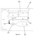
- Figures 2 and 3 show a schematic view of a preferred embodiment of such a device according to the invention.
- the assay device 10 has at least one sample zone 20, at least one reagent zone 30, at least one detection zone 40, and at least one wicking zone 50.
- the zones form a flow path by which sample flows from the sample zone to the wicking zone.
- Components of the assay device i.e., a physical structure of the device whether or not a discrete piece from other parts of the device
- device components can be prepared from copolymers, blends, laminates, metallized foils, metallized films or metals deposited one of the following materials: polyolefins, polyesters, styrene containing polymers, polycarbonate, acrylic polymers, chlorine containing polymers, acetal homopolymers and copolymers, cellulosics and their esters, cellulose nitrate, fluorine containing polymers, polyamides, polyimides, polymethylmethacrylates, sulfur containing polymers, polyurethanes, silicon containing polymers, glass, and ceramic materials.
- components of the device are made with a plastic, elastomer, latex, silicon chip, or metal; the elastomer can comprise polyethylene, polypropylene, polystyrene, polyacrylates, silicon elastomers, or latex.
- components of the device can be prepared from latex, polystyrene latex or hydrophobic polymers; the hydrophobic polymer can comprise polypropylene, polyethylene, or polyester.
- components of the device can comprise TEFLON®, polystyrene, polyacrylate, or polycarbonate.
- device components are made from plastics which are capable of being embossed, milled or injection molded or from surfaces of copper, silver and gold films upon which may be adsorbed various long chain alkanethiols.
- the structures of plastic which are capable of being milled or injection molded can comprise a polystyrene, a polycarbonate, or a polyacrylate.
- the assay device is injection molded from a cyclo olefin polymer, such as those sold under the name Zeonor®. Preferred injection molding techniques are described in U.S. Patent Nos. 6,372,542 , 6,733,682 , 6,811,736 , 6,884,370 , and 6,733,682 .
- the flow path can include open or closed paths, grooves, and capillaries.
- the flow path comprises a lateral flow path of adjacent projections, having a size, shape and mutual spacing such that capillary flow is sustained through the flow path.
- the flow path is in a channel within the substrate having a bottom surface and side walls.
- the projections protrude from the bottom surface of the channel.
- the side walls may or may not contribute to the capillary action of the liquid. If the sidewalls do not contribute to the capillary action of the liquid, then a gap can be provided between the outermost projections and the sidewalls to keep the liquid contained in the flow path defined by the projections.
- Figure 1 shows projections 7.
- the flow path is at least partially open. In another embodiment the flow path is entirely open. Open means that there is no lid or cover at a capillary distance. Thus the lid, if present as a physical protection for the flow path, does not contribute to the capillary flow in the flow path.
- An open lateral flow path is described for example in the following published applications: WO 2003/103835 , WO 2005/089082 ; WO 2005/118139 ; WO 2006/137785 ; and WO 2007/149042 .
- the projections have a height (H), diameter (D) and a distance or distances between the projections (t1, t2) such, that lateral capillary flow of the fluid, such as plasma, preferably human plasma, in the zone is achieved.
- the projections may be given a desired chemical, biological or physical functionality, e.g. by modifying the surface of the projections.
- the projections have a height in the interval of about 15 to about 150 ⁇ m, preferably about 30 to about 100 ⁇ m, a diameter of about 10 to about 160 ⁇ m, preferably 40 to about 100 ⁇ m, and a gap or gaps between the projections of about 3 to about 200 ⁇ m, preferably 10 to about 100 pm or 5 to 50 ⁇ m from each other.
- the flow channel may have a length of about 5 to about 500 mm, preferably about 10 to about 100 mm, and a width of about 0.3 to about 10 mm, preferably about 0.3 to about 3 mm, preferably about 0.5 to 1.5, and preferably about 0.5 to 1.2 mm.
- non-invasive, non-reactive sample integrity measurements may occur between the sample zone and the reagent zone or reagent addition zone, preferably after a filter element, if present.
- Other measurements may include blanks reads, one part of a two part reaction sequence as for measuring both hemoglobin and glycated hemoglobin for determination of HbA1 c, etc.
- the liquid sample zone 20 also referred to as the liquid sample addition zone, receives sample from a sample dispenser, such as a pipette.
- the sample is typically deposited onto the top of the zone.
- the sample addition zone is capable of transporting the liquid sample from the point where the sample is deposited to the reagent zone, through an optional filter and reagent addition zone, preferably through capillary flow.
- the capillary flow inducing structure can include porous materials, such as nitrocellulose, or preferably through projections, such as micro-pillars, as shown in Figure 1 . In those devices that can use finger stick volumes of blood, the sample can be directly touched off from the finger, or by a capillary pipette.
- a filter material (not shown) can be placed in the sample addition zone to filter particulates from the sample or to filter blood cells from blood so that plasma can travel further through the device.
- the reagent zone can include reagent(s) integrated into the analytical element and are generally reagents useful in the reaction---binding partners such as antibodies or antigens for immunoassays, substrates for enzyme assays, probes for molecular diagnostic assays, or are auxiliary materials such as materials that stabilize the integrated reagents, materials that suppress interfering reactions, etc.
- binding partners such as antibodies or antigens for immunoassays, substrates for enzyme assays, probes for molecular diagnostic assays, or are auxiliary materials such as materials that stabilize the integrated reagents, materials that suppress interfering reactions, etc.
- auxiliary materials such as materials that stabilize the integrated reagents, materials that suppress interfering reactions, etc.
- one of the reagents useful in the reaction bears a detectable signal as discussed below.
- the reagents may react with the analyte directly or through a cascade of reactions to form a detectable signal such as, but not restricted to, a molecule detectable using spectroscopy such as a colored or fluorescent molecule.
- the amount of reagent in the reagent zone can be adjusted by the length of reagent deposited into the device while maintaining the same reagent width.
- the amount of reagent can also be adjusted by changing the width while maintaining the length.
- the amount of reagent can further be adjusted by changing both width and length simultaneously.
- the reagent zone includes conjugate material.
- conjugate means any moiety bearing both a detection element and a binding partner.
- the detection element is an agent which is detectable with respect to its physical distribution or/and the intensity of the signal it delivers, such as but not limited to luminescent molecules (e.g. fluorescent agents, phosphorescent agents, chemiluminescent agents, bioluminescent agents and the like), colored molecules, molecules producing colors upon reaction, enzymes, radioisotopes, ligands exhibiting specific binding and the like.
- luminescent molecules e.g. fluorescent agents, phosphorescent agents, chemiluminescent agents, bioluminescent agents and the like
- colored molecules molecules producing colors upon reaction
- the detection element also referred to as a label is preferably chosen from chromophores, fluorophores, radioactive labels, and enzymes. Suitable labels are available from commercial suppliers, providing a wide range of dyes for the labeling of antibodies, proteins, and nucleic acids. There are, for example, fluorophores spanning practically the entire visible and in
- Suitable fluorescent or phosphorescent labels include for instance, but are not limited to, fluoresceins, Cy3, Cy5 and the like.
- Suitable chemoluminescent labels are for instance but are not limited to luminol, cyalume and the like.
- radioactive labels are commercially available, or detection elements can be synthesized so that they incorporate a radioactive label.
- Suitable radioactive labels are for instance but are not limited to radioactive iodine and phosphorus; e.g. 125 I and 32 P.
- Suitable enzymatic labels are, for instance, but are not limited to, horseradish peroxidase, beta-galactosidase, luciferase, alkaline phosphatase and the like. Two labels are "distinguishable" when they can be individually detected and preferably quantified simultaneously, without significantly disturbing, interfering or quenching each other. Two or more labels may be used, for example, when multiple analytes or markers are being detected.
- the binding partner is a material that can form a complex that can be used to determine the presence of or amount of an analyte.
- the binding partner in the conjugate can form a complex including the analyte and the conjugate and that complex can further bind to another binding partner, also called a capture element, integrated into the detection zone.
- another binding partner also called a capture element
- the analyte will interfere with binding of the binding partner in the conjugate to another binding partner, also called a capture element, integrated into the detection zone.
- Example binding partners included in conjugates include antibodies, antigens, analyte or analyte-mimics, protein, etc.
- a reagent addition zone is optionally located in the fluid flow path, before or after the reagent zone and before the detection zone.
- the reagent addition zone is shown as 35 in Figures 2 and 3 .
- the reagent addition zone can allow addition of a reagent externally from the device.
- the reagent addition zone may be used to add an interrupting reagent that may be used to wash the sample and other unbound components present in the fluid flow path into the wicking zone.
- the reagent addition zone 35 is located after the reagent zone 30.
- the detection zone 40 Downstream from the liquid sample zone and the reagent zone is the detection zone 40 which is in fluid communication with the sample addition zone.
- the detection zone 40 may include projections such as those described above. As also noted above, these projections are preferably integrally molded into the substrate from an optical plastic material such as Zeonor, such as injection molding or embossing.
- the width of the flow channel in the detection zone is typically on the order of 2mm for conventional size devices, however, some lower volume devices, such as those described above and in copending application entitled "Lower Volume Assay Device Having Increased Sensitivity" (Application No. 61/588758, first named inventor: Phil Hosimer) filed January 20, 2012 are significantly narrower, e.g., 1.5 mm or less.
- the detection zone is where any detectable signal is read.
- capture elements attached to the projections in the detection zone are capture elements.
- the capture elements can include binding partners for the conjugate or complexes containing the conjugate, as described above.
- the conjugate may be an antibody that will specifically bind that protein coupled to a detection element such as a fluorescence probe.
- the capture element could then be another antibody that also specifically binds to that protein.
- the capture molecule can be, but is not limited to, synthetic oligonucleotides, analogues thereof, or specific antibodies.
- Suitable capture elements include antibodies, antibody fragments, aptamers, and nucleic acid sequences, specific for the analyte to be detected.
- a non-limiting example of a suitable capture element is a molecule that bears avidin functionality that would bind to a conjugate containing a biotin functionality.
- the detection zone can include multiple detection zones. The multiple detection zones can be used for assays that include one or more markers. In the event of multiple detection zones, the capture elements can include multiple capture elements, such as first and second capture elements.
- the conjugate can be pre-deposited on the assay device, such as by coating in the reagent zone. Similarly the capture elements can be pre-deposited on the assay device on the detection zone. Preferably, both the detection and capture elements are pre-deposited on the assay device, on the reaction zone and detection zone, respectively.
- the reagent plume can contain any of the reagent materials that have been dissolved in the reaction zone or those added through the reagent addition zone.
- the reagent plume can include the conjugate having both the detection element and binding partner, in which case it is often referred to as a conjugate plume. As noted throughout, one challenge facing the inventors was to keep the reagent plume as wide as possible as it enters the detection zone.
- the reagent zone can include multiple reagent cells such as described in copending application "Assay Device Having Multiple Reagent Cells" (Serial No. 61/588738, first named inventor Zhong Ding) filed January 20, 2010 in which case multiple reagent plumes will exit the reagent zone to recombine partially or completely downstream.
- the present invention is based, in part, on the surprising discovery that in a device, where it may be possible to design a flow path to include corners to reduce the size and foot print of the device, simply fabricating corners or turns in the device, without more, will result in an assay device that has less signal that can be read by the detection instrument and poorer wash efficiency, and hence will result in assays having lower sensitivity.
- it was discovered that going around corners using projections, such as those described herein, having the same pattern as the straight sections of the detection zone will adversely affect the configuration of the flow front that is present as a sample progresses down the flow path of the assay device.
- a uniform flow front is the flow of the fluid, such as plasma, in the flow path, where the front edge of the fluid is substantially perpendicular to the direction of fluid flow.
- FIG. 4a-c the wetting of the flow path as observed from above is shown in Figures 4a-c .
- the direction of fluid flow is shown by arrow A in Figure 4a .
- the rows of pillars or projections 41 are shown as reference numbers 42a-42c.
- the projections or pillars 41 are patterned so that as the sample fluid advances from one row to the next, wetting occurs in a repeatable pattern by first wetting all pillars within a row.
- the fluid advances to the outside edges of the next row, such as shown in Figure 4b , where the fluid advances from row 42b to 42c along the outside edges 43, where the fluid will then wet the projections within row 42c as shown by arrow B, before advancing to the next row (not shown) along the outside edges.
- This ensures that the projections are uniformly wetted row by row and the flow front of the fluid is across the entire width of the flow path and is substantially perpendicular to the direction of fluid flow, i.e., a uniform flow front.
- Uniform flow across the entire width of the detection zone is important because the reagent plume containing the readable label or signal reagent that exits the reagent zone should cover as much of the width of the flow path as possible, such that the read window of the detection instrument, which is typically on the order of 1 mm, will read as much signal as possible, which is made possible by the reagent plume extending the entire width of the detection zone.
- a wide reagent plume relative to the detection zone width is particularly important in smaller assay devices where the width of the detection zone may be narrower.
- the inventors determined that the pillar geometry around the corner had to be modified or replaced altogether in order to maintain a uniform flow front in the flow path downstream of the corner section.
- one aspect of the invention provides modifying the configuration of the projections in or around the corner section to maintain a uniform flow front downstream of the corner section.
- modifying the configuration of the projections can include replacing the projections in the corner section altogether with other configurations as described in detail below. While any modification that maintains the configuration of the flow front after it exits the corner section as it had before the corner section (preferably uniform) can be used, the following modifications are particularly preferred.
- the corner sections can change the direction of the flow path by any desired amount.
- the change in direction is at least 30 degrees and can be up to 270 degrees, and preferably 90 degrees to 180 degrees.
- the projections are rotated before or after the turn to maintain the uniform flow profile after the turn.
- the amount rotated will depend on the change in the flow of direction. For example a flow path that turns 30° will have the projections rotated approximately 30°, whereas a flow path that turns 90° will have the projection rotated approximately 90°.
- Figure 6 shows the pillars rotated after the turn for a 90° change in flow direction.
- the rows 42a, 42b, 42c, etc., before they turn are perpendicular to the direction of flow. As the pillars move into the turn they maintain this configuration. If this configuration continued the rows would be parallel to the direction of fluid flow. Instead, the inventors have found that re-orienting the projections to where they form rows 42a', 42b', 42c', etc., after the turn ensures that the fluid maintains the configuration after the turn.
- contoured microchannels 45 without projections can be used at the turns or corners in place of projections as shown in Figure 7 .
- the flow rate across the channel is the same and the flow rate at the inlet and outlet will be the same as long as the distance between each microchannel is the same and the channel heights are the same.
- the relationship between W and R is shown in Figure 7 .
- the radius of the innermost flow channel is shown as R and the width as W, whereas the radius of the outermost flow channels is shown as R' and the width as W'.
- the smallest microchannel width can range from 5 ⁇ m to 30 ⁇ m. and preferably from 10 ⁇ m to 30 ⁇ m.
- the corner sections can change the direction of the flow path by any desired amount.
- the change in direction is at least 30 degrees and can be up to 270 degrees, and preferably 90 degrees to 180 degrees.
- a wicking zone Downstream from the detection zone is a wicking zone in fluid communication with the detection zone.
- the wicking zone is an area of the assay device with the capacity of receiving liquid sample and any other material in the flow path, e.g., unbound reagents, wash fluids, etc.
- the wicking zone provides a capillary force to continue moving the liquid sample through and out of the detection zone.
- the wicking zone can include a porous material such as nitrocellulose or can be a non-porous structure such as the projections described herein.
- the wicking zone can also include non-capillary fluid driving means, such as using evaporative heating or a pump.
- wicking zones as used in assay devices according to the present invention can be found in patent publications US 2005/0042766 and US 2006/0239859 . Wicking zones are also described in copending patent application entitled “Controlling Fluid Flow Through An Assay Device” (Application No. 61/588772, first named inventor: James Kanaley), filed January 20, 2012 .
- the entirety of the flow path including the sample addition zone, the detection zone and the wicking zone includes projections substantially vertical in relation to the substrate, and having a height, diameter and reciprocal spacing capable of creating lateral flow of the sample in the flow path.
- the device is preferably a disposable assay device.
- the assay device may be contained in a housing for ease of handling and protection. If the assay device is contained in such a housing, the housing will preferably include a port for adding sample to the assay device.
- the assay device of the present invention can be used with a device for reading (a reader) the result of an assay device performed on the assay of the present invention.
- the reader includes means for reading a signal emitted by, or reflected from the detection element, such as a photodetector, and means for computing the signal and displaying a result, such as microprocessor that may be included within an integrated reader or on a separate computer. Suitable readers are described for example in US 2007/0231883 and US Patent No. 7,416,700 .
- Another embodiment is a device for reading the result of an assay performed on an assay device, wherein the device comprises a detector capable of reading a signal emitted from or reflected from at least one detection element present in a defined location of the assay device.
- the reading preferably is chosen from the detection and/or quantification of color, fluorescence, radioactivity or enzymatic activity.
- Another aspect of the invention is directed to a method of performing an assay on a liquid sample for the detection of one or more analytes of interest.
- a liquid sample containing the analyte(s) of interest is deposited onto the sample addition zone of the assay device, such as through a port in the housing of the device, or by touching off a finger directly onto the sample addition zone in the case of a fingerstick blood draw.
- the sample moves by capillary action in the fluid flow path through an optional filter, and into the reagent zone where it dissolves the one or more reagents.
- the sample flows away from the reagent zone and optionally the reagent addition zone having a dissolved reagent plume and into the detection zone. At some point in the flow path, the flow will encounter a corner section, the uniform flow front of the sample and hence the width of the reagent plume is maintained by the modifications of the projections before, in or after the corner section according to the present invention.
- the sample moves by capillary action into the detection zone.
- a signal representative of an analyte or control is produced.
- the sample or the one or more reagents having a detection element is captured in the detection zone, such as by antibodies on the surface of the detection zone and a signal representative of the presence or concentration of the analyte(s) or control(s) is produced.
- the reader or detection instrument as described above is then used to read the signal that is produced in the detection zone to determine the presence or concentration of the analyte(s) or control(s).
- the sample moves from the detection zone and into the wicking zone.
- the reader may read the signal immediately or a short time after the sample has moved through the detection zone. Also, one or more washes may follow the sample through the device to wash any unbound reagents, such as detection element, away from the detection zone.
- Another aspect of the invention is a method of controlling the flow of a liquid around the corner section of a fluid flow path an assay device, which includes providing an assay device as described herein.
- the sample zone, the reagent zone, the detection zone and the wicking zone define a fluid flow path and at least a part of the fluid flow path has a substrate and projections which extend substantially vertically from the substrate.
- the projections have a height, cross-section and a distance between one another that defines a space between the projections capable of generating capillary flow parallel to the substrate surface.
- At least part of the fluid flow path having projections also has a corner section to change the direction of the flow path.
- the projections in or around the corner section are modified to maintain the flow front of the sample flowing through the flow path after the corner is substantially the same configuration as before the corner.
- Sample such as whole blood
- the sample flows from the sample addition through the reagent zone into and through the detection zone and into the wicking zone.
- the sample encounters a corner section where the modifications to the projections maintain the configuration of the flow front of the sample before and after the corner.
- the method, assay device, and reader according to an embodiment of the invention have many advantages, mainly related to the improved reaction kinetics of the immunochemical reactions and the increased sensitivity of the assay.
- Plastic substrate chips made of Zeonor (Zeon, Japan) having oxidized dextran on the surface for covalent immobilization of proteins via Schiff base coupling were used. Fluorescently labeled Anti-NT-proBNP monoclonal antibody was deposited and dried to create a reagent zone. Anti-NT-proBNP monoclonal antibody was deposited and dried to create a detection zone. A small amount of Triton X-45 was deposited on the device to increase wettability of the sample for better capillary flow. Sample was added to the sample zone of the device and the capillary action of the micropillar array distributed the sample through the flow channel into the wicking zone. A typical assay time was about 10 minutes.
- Figure 10 shows another embodiment of an assay device having two reagent cells 31 a and 31 b in the reagent zone 30.
- a reagent plume will flow from each of these cells and be distinct plumes for at least a portion of the subsequent detection zone 40.
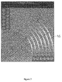
- Figure 11 shows a photograph showing flow around the corner according to one embodiment of the invention where the projections are rotated after the turn.
- the direction of flow is shown by arrows B and B'.
- the light colored shading shown as A and A' are distinct reagent plumes coming from reagent cells 31 a and 31 b before they have combined to form a single wide plume.
- the plumes are biased toward the inner edge of the flow channel as they round the corner. However, as the figure shows, the plumes return to substantially the same symmetry after completing the turn.
- Figure 12 shows a photograph showing flow around the corner according to one embodiment of the invention where contoured microchannels 45 are used at the corners instead of projections.
- the direction of flow is shown by arrows B and B'.
- the light colored shading shown as A and A' are distinct reagent plumes coming from reagent cells 31 a and 31 b before they have combined to form a single wide plume.
- the plumes retain substantially the same symmetry before, during and after the turn.
Landscapes
- Health & Medical Sciences (AREA)
- Chemical & Material Sciences (AREA)
- Life Sciences & Earth Sciences (AREA)
- Immunology (AREA)
- Hematology (AREA)
- Engineering & Computer Science (AREA)
- General Health & Medical Sciences (AREA)
- Analytical Chemistry (AREA)
- Molecular Biology (AREA)
- Biomedical Technology (AREA)
- Urology & Nephrology (AREA)
- General Physics & Mathematics (AREA)
- Pathology (AREA)
- Biochemistry (AREA)
- Physics & Mathematics (AREA)
- Biotechnology (AREA)
- Microbiology (AREA)
- Cell Biology (AREA)
- Food Science & Technology (AREA)
- Medicinal Chemistry (AREA)
- Clinical Laboratory Science (AREA)
- Chemical Kinetics & Catalysis (AREA)
- Dispersion Chemistry (AREA)
- Automatic Analysis And Handling Materials Therefor (AREA)
- Investigating Or Analysing Biological Materials (AREA)
- Apparatus Associated With Microorganisms And Enzymes (AREA)
Applications Claiming Priority (2)
| Application Number | Priority Date | Filing Date | Title |
|---|---|---|---|
| US201261588745P | 2012-01-20 | 2012-01-20 | |
| EP13151780.7A EP2618149B1 (de) | 2012-01-20 | 2013-01-18 | Analysevorrichtung mit einheitlicher Strömung um Ecken |
Related Parent Applications (2)
| Application Number | Title | Priority Date | Filing Date |
|---|---|---|---|
| EP13151780.7A Division EP2618149B1 (de) | 2012-01-20 | 2013-01-18 | Analysevorrichtung mit einheitlicher Strömung um Ecken |
| EP13151780.7A Division-Into EP2618149B1 (de) | 2012-01-20 | 2013-01-18 | Analysevorrichtung mit einheitlicher Strömung um Ecken |
Publications (2)
| Publication Number | Publication Date |
|---|---|
| EP3088892A1 true EP3088892A1 (de) | 2016-11-02 |
| EP3088892B1 EP3088892B1 (de) | 2018-07-25 |
Family
ID=47630173
Family Applications (2)
| Application Number | Title | Priority Date | Filing Date |
|---|---|---|---|
| EP13151780.7A Active EP2618149B1 (de) | 2012-01-20 | 2013-01-18 | Analysevorrichtung mit einheitlicher Strömung um Ecken |
| EP16174438.8A Active EP3088892B1 (de) | 2012-01-20 | 2013-01-18 | Analysevorrichtung mit einheitlicher umströmung um ecken |
Family Applications Before (1)
| Application Number | Title | Priority Date | Filing Date |
|---|---|---|---|
| EP13151780.7A Active EP2618149B1 (de) | 2012-01-20 | 2013-01-18 | Analysevorrichtung mit einheitlicher Strömung um Ecken |
Country Status (7)
| Country | Link |
|---|---|
| US (2) | US8895293B2 (de) |
| EP (2) | EP2618149B1 (de) |
| JP (1) | JP6133063B2 (de) |
| KR (1) | KR20130085991A (de) |
| CN (1) | CN103212455B (de) |
| BR (1) | BR102013001328A2 (de) |
| CA (1) | CA2802669C (de) |
Families Citing this family (18)
| Publication number | Priority date | Publication date | Assignee | Title |
|---|---|---|---|---|
| JP6395999B2 (ja) | 2012-01-20 | 2018-09-26 | オーソ−クリニカル・ダイアグノスティックス・インコーポレイテッドOrtho−Clinical Diagnostics, Inc. | アッセイ装置を通じた流体流の制御 |
| CA2833532C (en) | 2012-11-15 | 2021-10-26 | Ortho-Clinical Diagnostics, Inc. | Quality/process control of a lateral flow assay device based on flow monitoring |
| MX2015016017A (es) * | 2013-05-22 | 2016-06-21 | Imec Vzw | Dispositivo de analisis de fluido compacto y metodos para fabricarlo. |
| US10071373B2 (en) * | 2014-08-08 | 2018-09-11 | Ortho-Clinical Diagnostics, Inc. | Lateral-flow assay device having flow constrictions |
| US10073091B2 (en) | 2014-08-08 | 2018-09-11 | Ortho-Clinical Diagnostics, Inc. | Lateral flow assay device |
| US20170326552A1 (en) | 2014-11-26 | 2017-11-16 | Imec Vzw | Compact Fluid Analysis Device and Method to Fabricate |
| US10427156B2 (en) | 2014-11-26 | 2019-10-01 | Imec Vzw | Fluid analysis device |
| CN107636460A (zh) * | 2015-05-19 | 2018-01-26 | 奥索临床诊断有限公司 | 改善测定装置中液体样品流动的方法 |
| US10369567B2 (en) * | 2015-11-04 | 2019-08-06 | International Business Machines Corporation | Continuous, capacitance-based monitoring of liquid flows in a microfluidic device |
| AU2017212742A1 (en) | 2016-01-27 | 2018-07-26 | Undercover Colors, Inc. | Wearable apparatus for detecting a target substance in a liquid |
| US11446654B2 (en) | 2017-02-10 | 2022-09-20 | Quidel Corporation | Substrate with channels for controlled fluid flow |
| JP6919215B2 (ja) * | 2017-02-17 | 2021-08-18 | ソニーグループ株式会社 | マイクロチップ及び微小粒子分取装置 |
| BE1026910B1 (nl) | 2018-12-21 | 2020-07-22 | Pharmafluidics N V | Chemische reactoren |
| WO2021247335A1 (en) * | 2020-06-04 | 2021-12-09 | Aptavid Inc. | Viral diagnostics |
| CN113804658B (zh) * | 2020-06-11 | 2023-06-06 | 京东方科技集团股份有限公司 | 微流控流道结构、检测系统及其使用方法 |
| CN114100716B (zh) * | 2021-12-01 | 2023-04-21 | 上海天马微电子有限公司 | 微流控装置及其驱动方法 |
| EP4522981A2 (de) | 2022-05-13 | 2025-03-19 | University of Rochester | Multiplex-photonischer biosensor, system und verfahren |
| WO2026064707A1 (en) | 2024-09-23 | 2026-03-26 | University Of Rochester | Apparatus, method, and system for measuring enzyme activity and enzyme concentration |
Citations (24)
| Publication number | Priority date | Publication date | Assignee | Title |
|---|---|---|---|---|
| US5120643A (en) | 1987-07-13 | 1992-06-09 | Abbott Laboratories | Process for immunochromatography with colloidal particles |
| US5559041A (en) | 1989-12-18 | 1996-09-24 | Princeton Biomeditech Corporation | Immunoassay devices and materials |
| US5714389A (en) | 1988-06-27 | 1998-02-03 | Carter-Wallace, Inc. | Test device and method for colored particle immunoassay |
| US6139800A (en) | 1997-06-23 | 2000-10-31 | Luminex Corporation | Interlaced lasers for multiple fluorescence measurement |
| US6228660B1 (en) | 1908-04-27 | 2001-05-08 | Conopco Inc. | Capillary immunoassay and device therefor comprising mobilizable particulate labelled reagents |
| US6372542B1 (en) | 1998-02-17 | 2002-04-16 | Åmic AB | Method of component manufacture |
| US20030152927A1 (en) * | 2000-10-25 | 2003-08-14 | Jakobsen Mogens Havsteen | Closed substrate platforms suitable for analysis of biomolecules |
| WO2003103835A1 (en) | 2002-06-07 | 2003-12-18 | Åmic AB | Micro fluidic structures |
| US20040077103A1 (en) * | 1992-05-21 | 2004-04-22 | Biosite, Inc. | Diagnostic devices and apparatus for the controlled movement of reagents without membranes |
| US6733682B1 (en) | 1999-09-10 | 2004-05-11 | Amic Ab | Method for the manufacturing of a matrix and a matrix manufactured according to the method |
| US6811736B1 (en) | 1999-08-26 | 2004-11-02 | Gyros Ab | Method of producing a plastic product and an arrangement for moulding plastic products utilised therefor |
| US6884370B2 (en) | 1998-10-14 | 2005-04-26 | Amic Ab | Matrix and method of producing said matrix |
| WO2005089082A2 (en) | 2004-03-24 | 2005-09-29 | Åmic AB | Assay device and method |
| WO2005118139A1 (en) | 2004-06-02 | 2005-12-15 | Åmic AB | Controlled flow assay device and method |
| US20060285996A1 (en) | 2005-06-20 | 2006-12-21 | Amic Ab | Method and means for creating fluid transport |
| US20060289787A1 (en) | 2005-06-17 | 2006-12-28 | Amic Ab | Optical assay system |
| US20070122819A1 (en) * | 2005-11-25 | 2007-05-31 | Industrial Technology Research Institute | Analyte assay structure in microfluidic chip for quantitative analysis and method for using the same |
| US20070231883A1 (en) | 2006-03-22 | 2007-10-04 | Amic Ab | Flourescence reader |
| WO2007149042A1 (en) | 2006-06-20 | 2007-12-27 | Åmic AB | Assay device and method |
| US7416700B2 (en) | 1998-01-05 | 2008-08-26 | Biosite Incorporated | Immunoassay fluorometer |
| US7524464B2 (en) | 2003-09-26 | 2009-04-28 | Ahn Chong H | Smart disposable plastic lab-on-a-chip for point-of-care testing |
| US20090123336A1 (en) | 2007-11-08 | 2009-05-14 | The Ohio State University Research Foundation | Microfluidic chips for rapid multiplex elisa |
| US20090130658A1 (en) | 2004-10-15 | 2009-05-21 | Heike Barlag | Arrangement for integrated and automated dna or protein analysis in a single-use cartridge, method for producing such a cartridge and operating method for dna or protein analysis using such a cartridge |
| US20100167318A1 (en) | 2005-04-19 | 2010-07-01 | Vincent Linder | Fluidic Structures Including Meandering and Wide Channels |
Family Cites Families (18)
| Publication number | Priority date | Publication date | Assignee | Title |
|---|---|---|---|---|
| US6113855A (en) | 1996-11-15 | 2000-09-05 | Biosite Diagnostics, Inc. | Devices comprising multiple capillarity inducing surfaces |
| US5842787A (en) * | 1997-10-09 | 1998-12-01 | Caliper Technologies Corporation | Microfluidic systems incorporating varied channel dimensions |
| US6270641B1 (en) | 1999-04-26 | 2001-08-07 | Sandia Corporation | Method and apparatus for reducing sample dispersion in turns and junctions of microchannel systems |
| US6451264B1 (en) | 2000-01-28 | 2002-09-17 | Roche Diagnostics Corporation | Fluid flow control in curved capillary channels |
| US7005301B2 (en) * | 2002-06-10 | 2006-02-28 | Sandia National Laboratories | Piecewise uniform conduction-like flow channels and method therefor |
| WO2004084263A2 (en) | 2002-09-07 | 2004-09-30 | Arizona Board Of Regents | Integrated apparatus and methods for treating liquids |
| US20040259076A1 (en) | 2003-06-23 | 2004-12-23 | Accella Scientific, Inc. | Nano and micro-technology virus detection method and device |
| WO2007063719A1 (ja) * | 2005-11-29 | 2007-06-07 | Nec Corporation | 電気泳動チップ、電気泳動装置、および試料分析方法 |
| US7695687B2 (en) | 2006-06-30 | 2010-04-13 | International Business Machines Corporation | Capillary system for controlling the flow rate of fluids |
| SE529978C2 (sv) | 2007-04-16 | 2008-01-22 | Aamic Ab | Analysanordning för vätskeformiga prov |
| JP5345136B2 (ja) | 2007-05-23 | 2013-11-20 | ブレイエ・ユニバージテイト・ブリュッセル | 微細加工分離チャネルに試料及びキャリア液を分配する装置 |
| EP2304445B1 (de) * | 2008-07-09 | 2020-06-10 | Micropoint Bioscience Inc | Analysekassette mit flusssteuerung |
| CN101623660B (zh) * | 2008-07-09 | 2014-04-02 | 微点生物技术有限公司 | 具有液流控制的分析喷射筒 |
| CN102341491B (zh) * | 2009-03-20 | 2014-08-20 | 国际商业机器公司 | 微生物培养装置及其操作方法 |
| KR20130085994A (ko) | 2012-01-20 | 2013-07-30 | 오르토-클리니칼 다이아그노스틱스, 인코포레이티드 | 다수의 시약 셀을 갖는 분석 장치 |
| US10712340B2 (en) | 2012-01-20 | 2020-07-14 | Ortho-Clinical Diagnostics, Inc. | Assay device having controllable sample size |
| JP6395999B2 (ja) | 2012-01-20 | 2018-09-26 | オーソ−クリニカル・ダイアグノスティックス・インコーポレイテッドOrtho−Clinical Diagnostics, Inc. | アッセイ装置を通じた流体流の制御 |
| WO2013109821A1 (en) | 2012-01-20 | 2013-07-25 | Ortho-Clinical Diagnostics, Inc. | Assay device having multiplexing |
-
2013
- 2013-01-18 BR BRBR102013001328-5A patent/BR102013001328A2/pt not_active IP Right Cessation
- 2013-01-18 CA CA2802669A patent/CA2802669C/en active Active
- 2013-01-18 CN CN201310026252.7A patent/CN103212455B/zh not_active Expired - Fee Related
- 2013-01-18 KR KR1020130005869A patent/KR20130085991A/ko not_active Withdrawn
- 2013-01-18 JP JP2013007011A patent/JP6133063B2/ja not_active Expired - Fee Related
- 2013-01-18 EP EP13151780.7A patent/EP2618149B1/de active Active
- 2013-01-18 EP EP16174438.8A patent/EP3088892B1/de active Active
- 2013-01-18 US US13/744,451 patent/US8895293B2/en active Active
-
2014
- 2014-11-13 US US14/540,221 patent/US9625457B2/en not_active Expired - Fee Related
Patent Citations (27)
| Publication number | Priority date | Publication date | Assignee | Title |
|---|---|---|---|---|
| US6228660B1 (en) | 1908-04-27 | 2001-05-08 | Conopco Inc. | Capillary immunoassay and device therefor comprising mobilizable particulate labelled reagents |
| US5120643A (en) | 1987-07-13 | 1992-06-09 | Abbott Laboratories | Process for immunochromatography with colloidal particles |
| US5714389A (en) | 1988-06-27 | 1998-02-03 | Carter-Wallace, Inc. | Test device and method for colored particle immunoassay |
| US5559041A (en) | 1989-12-18 | 1996-09-24 | Princeton Biomeditech Corporation | Immunoassay devices and materials |
| US20040077103A1 (en) * | 1992-05-21 | 2004-04-22 | Biosite, Inc. | Diagnostic devices and apparatus for the controlled movement of reagents without membranes |
| US6139800A (en) | 1997-06-23 | 2000-10-31 | Luminex Corporation | Interlaced lasers for multiple fluorescence measurement |
| US7416700B2 (en) | 1998-01-05 | 2008-08-26 | Biosite Incorporated | Immunoassay fluorometer |
| US6372542B1 (en) | 1998-02-17 | 2002-04-16 | Åmic AB | Method of component manufacture |
| US6884370B2 (en) | 1998-10-14 | 2005-04-26 | Amic Ab | Matrix and method of producing said matrix |
| US6811736B1 (en) | 1999-08-26 | 2004-11-02 | Gyros Ab | Method of producing a plastic product and an arrangement for moulding plastic products utilised therefor |
| US6733682B1 (en) | 1999-09-10 | 2004-05-11 | Amic Ab | Method for the manufacturing of a matrix and a matrix manufactured according to the method |
| US20030152927A1 (en) * | 2000-10-25 | 2003-08-14 | Jakobsen Mogens Havsteen | Closed substrate platforms suitable for analysis of biomolecules |
| WO2003103835A1 (en) | 2002-06-07 | 2003-12-18 | Åmic AB | Micro fluidic structures |
| US20050042766A1 (en) | 2002-06-07 | 2005-02-24 | Amic Ab | Micro fluidic structures |
| US7524464B2 (en) | 2003-09-26 | 2009-04-28 | Ahn Chong H | Smart disposable plastic lab-on-a-chip for point-of-care testing |
| WO2005089082A2 (en) | 2004-03-24 | 2005-09-29 | Åmic AB | Assay device and method |
| WO2005118139A1 (en) | 2004-06-02 | 2005-12-15 | Åmic AB | Controlled flow assay device and method |
| US20060239859A1 (en) | 2004-06-02 | 2006-10-26 | Ohman Per O | Controlled flow assay device and method |
| US20090130658A1 (en) | 2004-10-15 | 2009-05-21 | Heike Barlag | Arrangement for integrated and automated dna or protein analysis in a single-use cartridge, method for producing such a cartridge and operating method for dna or protein analysis using such a cartridge |
| US20100167318A1 (en) | 2005-04-19 | 2010-07-01 | Vincent Linder | Fluidic Structures Including Meandering and Wide Channels |
| US20060289787A1 (en) | 2005-06-17 | 2006-12-28 | Amic Ab | Optical assay system |
| WO2006137785A1 (en) | 2005-06-20 | 2006-12-28 | Åmic AB | Method and means for creating fluid transport |
| US20060285996A1 (en) | 2005-06-20 | 2006-12-21 | Amic Ab | Method and means for creating fluid transport |
| US20070122819A1 (en) * | 2005-11-25 | 2007-05-31 | Industrial Technology Research Institute | Analyte assay structure in microfluidic chip for quantitative analysis and method for using the same |
| US20070231883A1 (en) | 2006-03-22 | 2007-10-04 | Amic Ab | Flourescence reader |
| WO2007149042A1 (en) | 2006-06-20 | 2007-12-27 | Åmic AB | Assay device and method |
| US20090123336A1 (en) | 2007-11-08 | 2009-05-14 | The Ohio State University Research Foundation | Microfluidic chips for rapid multiplex elisa |
Also Published As
| Publication number | Publication date |
|---|---|
| EP3088892B1 (de) | 2018-07-25 |
| CA2802669C (en) | 2020-08-11 |
| CN103212455B (zh) | 2016-12-28 |
| BR102013001328A2 (pt) | 2015-05-12 |
| KR20130085991A (ko) | 2013-07-30 |
| EP2618149B1 (de) | 2016-07-27 |
| US20150153337A1 (en) | 2015-06-04 |
| US20130189796A1 (en) | 2013-07-25 |
| JP6133063B2 (ja) | 2017-05-24 |
| US8895293B2 (en) | 2014-11-25 |
| CN103212455A (zh) | 2013-07-24 |
| JP2013148584A (ja) | 2013-08-01 |
| CA2802669A1 (en) | 2013-07-20 |
| EP2618149A1 (de) | 2013-07-24 |
| US9625457B2 (en) | 2017-04-18 |
Similar Documents
| Publication | Publication Date | Title |
|---|---|---|
| EP3088892B1 (de) | Analysevorrichtung mit einheitlicher umströmung um ecken | |
| EP2618153B1 (de) | Steuerung des Fluidstroms durch eine Analysevorrichtung | |
| EP2618150B1 (de) | Analysevorrichtung mit mehreren Reagenzienzellen | |
| EP2618151B1 (de) | Niedermengen-Analysevorrichtung mit gesteigerter Empfindlichkeit | |
| US20150153338A1 (en) | Low Volume Assay Device Having Increased Sensitivity | |
| US9927436B2 (en) | Reagent zone deposition pattern | |
| US20160018394A1 (en) | Assay Device Having Multiplexing |
Legal Events
| Date | Code | Title | Description |
|---|---|---|---|
| PUAI | Public reference made under article 153(3) epc to a published international application that has entered the european phase |
Free format text: ORIGINAL CODE: 0009012 |
|
| 17P | Request for examination filed |
Effective date: 20160620 |
|
| AC | Divisional application: reference to earlier application |
Ref document number: 2618149 Country of ref document: EP Kind code of ref document: P |
|
| AK | Designated contracting states |
Kind code of ref document: A1 Designated state(s): AL AT BE BG CH CY CZ DE DK EE ES FI FR GB GR HR HU IE IS IT LI LT LU LV MC MK MT NL NO PL PT RO RS SE SI SK SM TR |
|
| AX | Request for extension of the european patent |
Extension state: BA ME |
|
| STAA | Information on the status of an ep patent application or granted ep patent |
Free format text: STATUS: EXAMINATION IS IN PROGRESS |
|
| 17Q | First examination report despatched |
Effective date: 20170914 |
|
| GRAP | Despatch of communication of intention to grant a patent |
Free format text: ORIGINAL CODE: EPIDOSNIGR1 |
|
| STAA | Information on the status of an ep patent application or granted ep patent |
Free format text: STATUS: GRANT OF PATENT IS INTENDED |
|
| INTG | Intention to grant announced |
Effective date: 20180228 |
|
| GRAS | Grant fee paid |
Free format text: ORIGINAL CODE: EPIDOSNIGR3 |
|
| GRAA | (expected) grant |
Free format text: ORIGINAL CODE: 0009210 |
|
| STAA | Information on the status of an ep patent application or granted ep patent |
Free format text: STATUS: THE PATENT HAS BEEN GRANTED |
|
| AC | Divisional application: reference to earlier application |
Ref document number: 2618149 Country of ref document: EP Kind code of ref document: P |
|
| AK | Designated contracting states |
Kind code of ref document: B1 Designated state(s): AL AT BE BG CH CY CZ DE DK EE ES FI FR GB GR HR HU IE IS IT LI LT LU LV MC MK MT NL NO PL PT RO RS SE SI SK SM TR |
|
| REG | Reference to a national code |
Ref country code: GB Ref legal event code: FG4D |
|
| REG | Reference to a national code |
Ref country code: CH Ref legal event code: EP |
|
| REG | Reference to a national code |
Ref country code: AT Ref legal event code: REF Ref document number: 1022317 Country of ref document: AT Kind code of ref document: T Effective date: 20180815 |
|
| REG | Reference to a national code |
Ref country code: IE Ref legal event code: FG4D |
|
| REG | Reference to a national code |
Ref country code: DE Ref legal event code: R096 Ref document number: 602013041028 Country of ref document: DE |
|
| REG | Reference to a national code |
Ref country code: SE Ref legal event code: TRGR |
|
| REG | Reference to a national code |
Ref country code: NL Ref legal event code: MP Effective date: 20180725 |
|
| REG | Reference to a national code |
Ref country code: LT Ref legal event code: MG4D |
|
| PG25 | Lapsed in a contracting state [announced via postgrant information from national office to epo] |
Ref country code: NL Free format text: LAPSE BECAUSE OF FAILURE TO SUBMIT A TRANSLATION OF THE DESCRIPTION OR TO PAY THE FEE WITHIN THE PRESCRIBED TIME-LIMIT Effective date: 20180725 |
|
| REG | Reference to a national code |
Ref country code: AT Ref legal event code: MK05 Ref document number: 1022317 Country of ref document: AT Kind code of ref document: T Effective date: 20180725 |
|
| PG25 | Lapsed in a contracting state [announced via postgrant information from national office to epo] |
Ref country code: LT Free format text: LAPSE BECAUSE OF FAILURE TO SUBMIT A TRANSLATION OF THE DESCRIPTION OR TO PAY THE FEE WITHIN THE PRESCRIBED TIME-LIMIT Effective date: 20180725 Ref country code: PL Free format text: LAPSE BECAUSE OF FAILURE TO SUBMIT A TRANSLATION OF THE DESCRIPTION OR TO PAY THE FEE WITHIN THE PRESCRIBED TIME-LIMIT Effective date: 20180725 Ref country code: IS Free format text: LAPSE BECAUSE OF FAILURE TO SUBMIT A TRANSLATION OF THE DESCRIPTION OR TO PAY THE FEE WITHIN THE PRESCRIBED TIME-LIMIT Effective date: 20181125 Ref country code: RS Free format text: LAPSE BECAUSE OF FAILURE TO SUBMIT A TRANSLATION OF THE DESCRIPTION OR TO PAY THE FEE WITHIN THE PRESCRIBED TIME-LIMIT Effective date: 20180725 Ref country code: FI Free format text: LAPSE BECAUSE OF FAILURE TO SUBMIT A TRANSLATION OF THE DESCRIPTION OR TO PAY THE FEE WITHIN THE PRESCRIBED TIME-LIMIT Effective date: 20180725 Ref country code: GR Free format text: LAPSE BECAUSE OF FAILURE TO SUBMIT A TRANSLATION OF THE DESCRIPTION OR TO PAY THE FEE WITHIN THE PRESCRIBED TIME-LIMIT Effective date: 20181026 Ref country code: NO Free format text: LAPSE BECAUSE OF FAILURE TO SUBMIT A TRANSLATION OF THE DESCRIPTION OR TO PAY THE FEE WITHIN THE PRESCRIBED TIME-LIMIT Effective date: 20181025 Ref country code: BG Free format text: LAPSE BECAUSE OF FAILURE TO SUBMIT A TRANSLATION OF THE DESCRIPTION OR TO PAY THE FEE WITHIN THE PRESCRIBED TIME-LIMIT Effective date: 20181025 Ref country code: AT Free format text: LAPSE BECAUSE OF FAILURE TO SUBMIT A TRANSLATION OF THE DESCRIPTION OR TO PAY THE FEE WITHIN THE PRESCRIBED TIME-LIMIT Effective date: 20180725 |
|
| PG25 | Lapsed in a contracting state [announced via postgrant information from national office to epo] |
Ref country code: HR Free format text: LAPSE BECAUSE OF FAILURE TO SUBMIT A TRANSLATION OF THE DESCRIPTION OR TO PAY THE FEE WITHIN THE PRESCRIBED TIME-LIMIT Effective date: 20180725 Ref country code: LV Free format text: LAPSE BECAUSE OF FAILURE TO SUBMIT A TRANSLATION OF THE DESCRIPTION OR TO PAY THE FEE WITHIN THE PRESCRIBED TIME-LIMIT Effective date: 20180725 Ref country code: AL Free format text: LAPSE BECAUSE OF FAILURE TO SUBMIT A TRANSLATION OF THE DESCRIPTION OR TO PAY THE FEE WITHIN THE PRESCRIBED TIME-LIMIT Effective date: 20180725 |
|
| REG | Reference to a national code |
Ref country code: DE Ref legal event code: R097 Ref document number: 602013041028 Country of ref document: DE |
|
| PG25 | Lapsed in a contracting state [announced via postgrant information from national office to epo] |
Ref country code: CZ Free format text: LAPSE BECAUSE OF FAILURE TO SUBMIT A TRANSLATION OF THE DESCRIPTION OR TO PAY THE FEE WITHIN THE PRESCRIBED TIME-LIMIT Effective date: 20180725 Ref country code: ES Free format text: LAPSE BECAUSE OF FAILURE TO SUBMIT A TRANSLATION OF THE DESCRIPTION OR TO PAY THE FEE WITHIN THE PRESCRIBED TIME-LIMIT Effective date: 20180725 Ref country code: RO Free format text: LAPSE BECAUSE OF FAILURE TO SUBMIT A TRANSLATION OF THE DESCRIPTION OR TO PAY THE FEE WITHIN THE PRESCRIBED TIME-LIMIT Effective date: 20180725 Ref country code: EE Free format text: LAPSE BECAUSE OF FAILURE TO SUBMIT A TRANSLATION OF THE DESCRIPTION OR TO PAY THE FEE WITHIN THE PRESCRIBED TIME-LIMIT Effective date: 20180725 |
|
| PG25 | Lapsed in a contracting state [announced via postgrant information from national office to epo] |
Ref country code: DK Free format text: LAPSE BECAUSE OF FAILURE TO SUBMIT A TRANSLATION OF THE DESCRIPTION OR TO PAY THE FEE WITHIN THE PRESCRIBED TIME-LIMIT Effective date: 20180725 Ref country code: SK Free format text: LAPSE BECAUSE OF FAILURE TO SUBMIT A TRANSLATION OF THE DESCRIPTION OR TO PAY THE FEE WITHIN THE PRESCRIBED TIME-LIMIT Effective date: 20180725 Ref country code: SM Free format text: LAPSE BECAUSE OF FAILURE TO SUBMIT A TRANSLATION OF THE DESCRIPTION OR TO PAY THE FEE WITHIN THE PRESCRIBED TIME-LIMIT Effective date: 20180725 |
|
| PLBE | No opposition filed within time limit |
Free format text: ORIGINAL CODE: 0009261 |
|
| STAA | Information on the status of an ep patent application or granted ep patent |
Free format text: STATUS: NO OPPOSITION FILED WITHIN TIME LIMIT |
|
| 26N | No opposition filed |
Effective date: 20190426 |
|
| PG25 | Lapsed in a contracting state [announced via postgrant information from national office to epo] |
Ref country code: SI Free format text: LAPSE BECAUSE OF FAILURE TO SUBMIT A TRANSLATION OF THE DESCRIPTION OR TO PAY THE FEE WITHIN THE PRESCRIBED TIME-LIMIT Effective date: 20180725 Ref country code: MC Free format text: LAPSE BECAUSE OF FAILURE TO SUBMIT A TRANSLATION OF THE DESCRIPTION OR TO PAY THE FEE WITHIN THE PRESCRIBED TIME-LIMIT Effective date: 20180725 |
|
| PG25 | Lapsed in a contracting state [announced via postgrant information from national office to epo] |
Ref country code: LU Free format text: LAPSE BECAUSE OF NON-PAYMENT OF DUE FEES Effective date: 20190118 |
|
| REG | Reference to a national code |
Ref country code: BE Ref legal event code: MM Effective date: 20190131 |
|
| PG25 | Lapsed in a contracting state [announced via postgrant information from national office to epo] |
Ref country code: BE Free format text: LAPSE BECAUSE OF NON-PAYMENT OF DUE FEES Effective date: 20190131 |
|
| PG25 | Lapsed in a contracting state [announced via postgrant information from national office to epo] |
Ref country code: TR Free format text: LAPSE BECAUSE OF FAILURE TO SUBMIT A TRANSLATION OF THE DESCRIPTION OR TO PAY THE FEE WITHIN THE PRESCRIBED TIME-LIMIT Effective date: 20180725 |
|
| PG25 | Lapsed in a contracting state [announced via postgrant information from national office to epo] |
Ref country code: PT Free format text: LAPSE BECAUSE OF FAILURE TO SUBMIT A TRANSLATION OF THE DESCRIPTION OR TO PAY THE FEE WITHIN THE PRESCRIBED TIME-LIMIT Effective date: 20181125 Ref country code: MT Free format text: LAPSE BECAUSE OF NON-PAYMENT OF DUE FEES Effective date: 20190118 |
|
| PG25 | Lapsed in a contracting state [announced via postgrant information from national office to epo] |
Ref country code: CY Free format text: LAPSE BECAUSE OF FAILURE TO SUBMIT A TRANSLATION OF THE DESCRIPTION OR TO PAY THE FEE WITHIN THE PRESCRIBED TIME-LIMIT Effective date: 20180725 |
|
| PG25 | Lapsed in a contracting state [announced via postgrant information from national office to epo] |
Ref country code: HU Free format text: LAPSE BECAUSE OF FAILURE TO SUBMIT A TRANSLATION OF THE DESCRIPTION OR TO PAY THE FEE WITHIN THE PRESCRIBED TIME-LIMIT; INVALID AB INITIO Effective date: 20130118 |
|
| PG25 | Lapsed in a contracting state [announced via postgrant information from national office to epo] |
Ref country code: MK Free format text: LAPSE BECAUSE OF FAILURE TO SUBMIT A TRANSLATION OF THE DESCRIPTION OR TO PAY THE FEE WITHIN THE PRESCRIBED TIME-LIMIT Effective date: 20180725 |
|
| P01 | Opt-out of the competence of the unified patent court (upc) registered |
Effective date: 20230718 |
|
| PGFP | Annual fee paid to national office [announced via postgrant information from national office to epo] |
Ref country code: GB Payment date: 20231130 Year of fee payment: 12 |
|
| PGFP | Annual fee paid to national office [announced via postgrant information from national office to epo] |
Ref country code: SE Payment date: 20231213 Year of fee payment: 12 Ref country code: IE Payment date: 20231211 Year of fee payment: 12 Ref country code: FR Payment date: 20231212 Year of fee payment: 12 |
|
| PGFP | Annual fee paid to national office [announced via postgrant information from national office to epo] |
Ref country code: DE Payment date: 20231205 Year of fee payment: 12 Ref country code: CH Payment date: 20240201 Year of fee payment: 12 |
|
| PGFP | Annual fee paid to national office [announced via postgrant information from national office to epo] |
Ref country code: IT Payment date: 20231212 Year of fee payment: 12 |
|
| REG | Reference to a national code |
Ref country code: DE Ref legal event code: R119 Ref document number: 602013041028 Country of ref document: DE |
|
| REG | Reference to a national code |
Ref country code: CH Ref legal event code: PL |
|
| REG | Reference to a national code |
Ref country code: SE Ref legal event code: EUG |
|
| GBPC | Gb: european patent ceased through non-payment of renewal fee |
Effective date: 20250118 |
|
| PG25 | Lapsed in a contracting state [announced via postgrant information from national office to epo] |
Ref country code: DE Free format text: LAPSE BECAUSE OF NON-PAYMENT OF DUE FEES Effective date: 20250801 |
|
| PG25 | Lapsed in a contracting state [announced via postgrant information from national office to epo] |
Ref country code: GB Free format text: LAPSE BECAUSE OF NON-PAYMENT OF DUE FEES Effective date: 20250118 |
|
| PG25 | Lapsed in a contracting state [announced via postgrant information from national office to epo] |
Ref country code: FR Free format text: LAPSE BECAUSE OF NON-PAYMENT OF DUE FEES Effective date: 20250131 |
|
| PG25 | Lapsed in a contracting state [announced via postgrant information from national office to epo] |
Ref country code: CH Free format text: LAPSE BECAUSE OF NON-PAYMENT OF DUE FEES Effective date: 20250131 |
|
| PG25 | Lapsed in a contracting state [announced via postgrant information from national office to epo] |
Ref country code: IE Free format text: LAPSE BECAUSE OF NON-PAYMENT OF DUE FEES Effective date: 20250118 |