EP3088936B1 - Dispositif d'affichage - Google Patents
Dispositif d'affichage Download PDFInfo
- Publication number
- EP3088936B1 EP3088936B1 EP15177642.4A EP15177642A EP3088936B1 EP 3088936 B1 EP3088936 B1 EP 3088936B1 EP 15177642 A EP15177642 A EP 15177642A EP 3088936 B1 EP3088936 B1 EP 3088936B1
- Authority
- EP
- European Patent Office
- Prior art keywords
- pixel
- sub pixels
- sub
- stereoscopic
- pixels
- Prior art date
- Legal status (The legal status is an assumption and is not a legal conclusion. Google has not performed a legal analysis and makes no representation as to the accuracy of the status listed.)
- Not-in-force
Links
Images








Classifications
-
- H—ELECTRICITY
- H04—ELECTRIC COMMUNICATION TECHNIQUE
- H04N—PICTORIAL COMMUNICATION, e.g. TELEVISION
- H04N13/00—Stereoscopic video systems; Multi-view video systems; Details thereof
- H04N13/30—Image reproducers
- H04N13/302—Image reproducers for viewing without the aid of special glasses, i.e. using autostereoscopic displays
- H04N13/31—Image reproducers for viewing without the aid of special glasses, i.e. using autostereoscopic displays using parallax barriers
-
- G—PHYSICS
- G02—OPTICS
- G02B—OPTICAL ELEMENTS, SYSTEMS OR APPARATUS
- G02B30/00—Optical systems or apparatus for producing three-dimensional [3D] effects, e.g. stereoscopic images
- G02B30/20—Optical systems or apparatus for producing three-dimensional [3D] effects, e.g. stereoscopic images by providing first and second parallax images to an observer's left and right eyes
- G02B30/26—Optical systems or apparatus for producing three-dimensional [3D] effects, e.g. stereoscopic images by providing first and second parallax images to an observer's left and right eyes of the autostereoscopic type
- G02B30/27—Optical systems or apparatus for producing three-dimensional [3D] effects, e.g. stereoscopic images by providing first and second parallax images to an observer's left and right eyes of the autostereoscopic type involving lenticular arrays
-
- G—PHYSICS
- G02—OPTICS
- G02B—OPTICAL ELEMENTS, SYSTEMS OR APPARATUS
- G02B30/00—Optical systems or apparatus for producing three-dimensional [3D] effects, e.g. stereoscopic images
- G02B30/20—Optical systems or apparatus for producing three-dimensional [3D] effects, e.g. stereoscopic images by providing first and second parallax images to an observer's left and right eyes
- G02B30/26—Optical systems or apparatus for producing three-dimensional [3D] effects, e.g. stereoscopic images by providing first and second parallax images to an observer's left and right eyes of the autostereoscopic type
- G02B30/30—Optical systems or apparatus for producing three-dimensional [3D] effects, e.g. stereoscopic images by providing first and second parallax images to an observer's left and right eyes of the autostereoscopic type involving parallax barriers
- G02B30/31—Optical systems or apparatus for producing three-dimensional [3D] effects, e.g. stereoscopic images by providing first and second parallax images to an observer's left and right eyes of the autostereoscopic type involving parallax barriers involving active parallax barriers
-
- G—PHYSICS
- G09—EDUCATION; CRYPTOGRAPHY; DISPLAY; ADVERTISING; SEALS
- G09G—ARRANGEMENTS OR CIRCUITS FOR CONTROL OF INDICATING DEVICES USING STATIC MEANS TO PRESENT VARIABLE INFORMATION
- G09G3/00—Control arrangements or circuits, of interest only in connection with visual indicators other than cathode-ray tubes
- G09G3/20—Control arrangements or circuits, of interest only in connection with visual indicators other than cathode-ray tubes for presentation of an assembly of a number of characters, e.g. a page, by composing the assembly by combination of individual elements arranged in a matrix no fixed position being assigned to or needed to be assigned to the individual characters or partial characters
- G09G3/2007—Display of intermediate tones
- G09G3/207—Display of intermediate tones by domain size control
-
- H—ELECTRICITY
- H04—ELECTRIC COMMUNICATION TECHNIQUE
- H04N—PICTORIAL COMMUNICATION, e.g. TELEVISION
- H04N13/00—Stereoscopic video systems; Multi-view video systems; Details thereof
- H04N13/30—Image reproducers
- H04N13/324—Colour aspects
-
- H—ELECTRICITY
- H04—ELECTRIC COMMUNICATION TECHNIQUE
- H04N—PICTORIAL COMMUNICATION, e.g. TELEVISION
- H04N13/00—Stereoscopic video systems; Multi-view video systems; Details thereof
- H04N13/30—Image reproducers
- H04N13/398—Synchronisation thereof; Control thereof
-
- G—PHYSICS
- G09—EDUCATION; CRYPTOGRAPHY; DISPLAY; ADVERTISING; SEALS
- G09G—ARRANGEMENTS OR CIRCUITS FOR CONTROL OF INDICATING DEVICES USING STATIC MEANS TO PRESENT VARIABLE INFORMATION
- G09G2300/00—Aspects of the constitution of display devices
- G09G2300/04—Structural and physical details of display devices
- G09G2300/0421—Structural details of the set of electrodes
- G09G2300/0426—Layout of electrodes and connections
-
- G—PHYSICS
- G09—EDUCATION; CRYPTOGRAPHY; DISPLAY; ADVERTISING; SEALS
- G09G—ARRANGEMENTS OR CIRCUITS FOR CONTROL OF INDICATING DEVICES USING STATIC MEANS TO PRESENT VARIABLE INFORMATION
- G09G2300/00—Aspects of the constitution of display devices
- G09G2300/04—Structural and physical details of display devices
- G09G2300/0439—Pixel structures
- G09G2300/0443—Pixel structures with several sub-pixels for the same colour in a pixel, not specifically used to display gradations
-
- G—PHYSICS
- G09—EDUCATION; CRYPTOGRAPHY; DISPLAY; ADVERTISING; SEALS
- G09G—ARRANGEMENTS OR CIRCUITS FOR CONTROL OF INDICATING DEVICES USING STATIC MEANS TO PRESENT VARIABLE INFORMATION
- G09G2300/00—Aspects of the constitution of display devices
- G09G2300/04—Structural and physical details of display devices
- G09G2300/0439—Pixel structures
- G09G2300/0452—Details of colour pixel setup, e.g. pixel composed of a red, a blue and two green components
-
- G—PHYSICS
- G09—EDUCATION; CRYPTOGRAPHY; DISPLAY; ADVERTISING; SEALS
- G09G—ARRANGEMENTS OR CIRCUITS FOR CONTROL OF INDICATING DEVICES USING STATIC MEANS TO PRESENT VARIABLE INFORMATION
- G09G2300/00—Aspects of the constitution of display devices
- G09G2300/04—Structural and physical details of display devices
- G09G2300/0439—Pixel structures
- G09G2300/0465—Improved aperture ratio, e.g. by size reduction of the pixel circuit, e.g. for improving the pixel density or the maximum displayable luminance or brightness
-
- G—PHYSICS
- G09—EDUCATION; CRYPTOGRAPHY; DISPLAY; ADVERTISING; SEALS
- G09G—ARRANGEMENTS OR CIRCUITS FOR CONTROL OF INDICATING DEVICES USING STATIC MEANS TO PRESENT VARIABLE INFORMATION
- G09G3/00—Control arrangements or circuits, of interest only in connection with visual indicators other than cathode-ray tubes
- G09G3/20—Control arrangements or circuits, of interest only in connection with visual indicators other than cathode-ray tubes for presentation of an assembly of a number of characters, e.g. a page, by composing the assembly by combination of individual elements arranged in a matrix no fixed position being assigned to or needed to be assigned to the individual characters or partial characters
- G09G3/2007—Display of intermediate tones
- G09G3/2074—Display of intermediate tones using sub-pixels
-
- G—PHYSICS
- G09—EDUCATION; CRYPTOGRAPHY; DISPLAY; ADVERTISING; SEALS
- G09G—ARRANGEMENTS OR CIRCUITS FOR CONTROL OF INDICATING DEVICES USING STATIC MEANS TO PRESENT VARIABLE INFORMATION
- G09G3/00—Control arrangements or circuits, of interest only in connection with visual indicators other than cathode-ray tubes
- G09G3/20—Control arrangements or circuits, of interest only in connection with visual indicators other than cathode-ray tubes for presentation of an assembly of a number of characters, e.g. a page, by composing the assembly by combination of individual elements arranged in a matrix no fixed position being assigned to or needed to be assigned to the individual characters or partial characters
- G09G3/22—Control arrangements or circuits, of interest only in connection with visual indicators other than cathode-ray tubes for presentation of an assembly of a number of characters, e.g. a page, by composing the assembly by combination of individual elements arranged in a matrix no fixed position being assigned to or needed to be assigned to the individual characters or partial characters using controlled light sources
- G09G3/30—Control arrangements or circuits, of interest only in connection with visual indicators other than cathode-ray tubes for presentation of an assembly of a number of characters, e.g. a page, by composing the assembly by combination of individual elements arranged in a matrix no fixed position being assigned to or needed to be assigned to the individual characters or partial characters using controlled light sources using electroluminescent panels
- G09G3/32—Control arrangements or circuits, of interest only in connection with visual indicators other than cathode-ray tubes for presentation of an assembly of a number of characters, e.g. a page, by composing the assembly by combination of individual elements arranged in a matrix no fixed position being assigned to or needed to be assigned to the individual characters or partial characters using controlled light sources using electroluminescent panels semiconductive, e.g. using light-emitting diodes [LED]
- G09G3/3208—Control arrangements or circuits, of interest only in connection with visual indicators other than cathode-ray tubes for presentation of an assembly of a number of characters, e.g. a page, by composing the assembly by combination of individual elements arranged in a matrix no fixed position being assigned to or needed to be assigned to the individual characters or partial characters using controlled light sources using electroluminescent panels semiconductive, e.g. using light-emitting diodes [LED] organic, e.g. using organic light-emitting diodes [OLED]
Definitions
- the exemplary embodiments relate to a display device for displaying a stereoscopic image.
- a display device capable of 3-dimensional stereoscopic expression for expressing an image that is stereoscopic and realistic.
- a stereoscopic image providing 3-dimensional expression is formed by a principle of stereopsis using both eyes. Since both eyes are separated from each other by about 65 mm, an image with a stereoscopic effect can be displayed using binocular parallax.
- a technique for displaying a stereoscopic image there are known stereoscopic image display of glass type and stereoscopic image display of no-glass type.
- a stereoscopic image display method of no-glass type there are known a parallax barrier method in which vertical grid-like openings are placed in front of respective images for left and right eyes so that the images are separately observed via the openings, a lenticular method using a lenticular plate formed by semicylindrical lenses arranged in a stripe shape, and an integral photography method using a fly-eye lens plate.
- the above methods can also be taken as a parallax method in which stereoscopic images for left eye and right eye (left-eye viewpoint image and right-eye viewpoint image) are configured to be separately visible, thereby realizing a 3-dimensional image.
- a parallax barrier method a parallax barrier is placed which has slit-like openings vertically or horizontally formed being opposed to a surface of display elements on which image information for left eye and right eye is displayed, so that an image that should enter a left eye is shut out of a right eye and an image that should enter a right eye is shut out of a left eye, thereby eventually allowing a user to view a 3-dimensional stereoscopic image owing to binocular parallax.
- one pixel is composed of sub pixels for a plurality of colors such as RGB.
- a stereoscopic image display device having sub pixels of RGB repeatedly arranged in the vertical direction.
- a stereoscopic image display device having stripe-like barriers set in the vertical direction and the horizontal direction so that a stereoscopic image is visible even when a screen is turned by 90 degrees.
- Document US 2012/050857 relates to a stereoscopic 3D display device, wherein a first and second parallax barrier selectively allows different pixels depending on if the display device is used in a landscape or portrait mode.
- the positions of both eyes slightly move (shift) leftward or rightward from an appropriate position (for example, an exactly front position) for the observer to view stereoscopic display.
- an appropriate position for example, an exactly front position
- the parallax barrier appears to be shifted rightward as a whole. That is, the parallax barrier overlaps on a part of the sub pixel.
- degrees to which the parallax barrier overlaps on the sub pixels of RGB are equal. Therefore, amounts of red, green, and blue entering a right eye and left eye decrease or increase at the same rate.
- a screen is turned by 90 degrees from the above state and the screen is viewed in the landscape mode.
- the sub pixels are arranged in order of R, G, then B in the horizontal direction as seen from the observer. That is, sub pixels for each of red, green and blue are arranged in one line in the vertical direction as seen from the observer.
- the positions of both eyes slightly move leftward from an appropriate position for the observer to view stereoscopic display as described above (the parallax barrier appears to be shifted rightward as a whole).
- the exemplary embodiments will be given to describe a display device capable of displaying a stereoscopic image such that the stereoscopic image is visible even if a screen is changed from a predetermined orientation, while maintaining a color display quality in a preferred state before and after the change.
- the display device for displaying a stereoscopic image composed of an image for right eye and an image for left eye.
- the display device includes an image display portion, a display mode setting portion, a parallax barrier forming portion, and an image control portion.
- the image display portion has a plurality of stereoscopic pixels each composed of a pixel for right eye and a pixel for left eye, the plurality of stereoscopic pixels being arranged in a horizontal direction and in a vertical direction.
- the display mode setting portion is configured to set one of at least a vertical display mode and a horizontal display mode.
- the parallax barrier forming portion is configured to form a parallax barrier in accordance with the setting by the display mode setting portion.
- the image control portion is configured to control the image display portion in accordance with the setting by the display mode setting portion.
- the pixel for right eye and the pixel for left eye each include at least one sub pixel for each of red, blue, and green.
- the image control portion is configured to, when the vertical display mode is set, not allow the sub pixels at first intervals in the horizontal direction to emit color lights, but allow the sub pixels at second intervals in the vertical direction to emit color lights, and when the horizontal display mode is set, not allow the sub pixels at the second intervals in the vertical direction to emit color lights, but allow the sub pixels at the first intervals in the horizontal direction to emit color lights.
- control for allowing or not allowing color light emission by the image control portion may be performed on sub pixels for one of red, blue, and green. Further, the color of such sub pixels may be green.
- the number of sub pixels for a color for which control for allowing or not allowing color light emission is performed by the image control portion may be larger than the respective numbers of sub pixels for the other colors. Further, a total area of such sub pixels may be greater than respective total areas of sub pixels for the other colors.
- sub pixels for the other colors may not be located.
- each of a column and a row that are respectively adjacent to each of a column and a row in which only sub pixels for a color for which control for allowing or not allowing color light emission is performed by the image control portion are located at least one sub pixel for each of red, blue, and green may be located.
- the image control portion may be configured to, when the vertical display mode is set, not allow sub pixels in columns present at the first intervals in the horizontal direction to emit color lights, but allow sub pixels in rows present at the second intervals in the vertical direction to emit color lights, and when the horizontal display mode is set, not allow sub pixels in columns present at the second intervals in the vertical direction to emit color lights, but allow sub pixels in rows present at the first intervals in the horizontal direction to emit color lights.
- the image control portion may be configured to, when the vertical display mode is set, not allow sub pixels at even-numbered locations in the horizontal direction to emit color lights, but allow sub pixels at even-numbered locations in the vertical direction to emit color lights, and when the horizontal display mode is set, not allow sub pixels at even-numbered locations in the vertical direction to emit color lights, but allow sub pixels at even-numbered locations in the horizontal direction to emit color lights.
- the image control portion may be configured to, when the vertical display mode is set, not allow sub pixels at odd-numbered locations in the horizontal direction to emit color lights, but allow sub pixels at odd-numbered locations in the vertical direction to emit color lights, and when the horizontal display mode is set, not allow sub pixels at odd-numbered locations in the vertical direction to emit color lights, but allow sub pixels at odd-numbered locations in the horizontal direction to emit color lights.
- the stereoscopic pixel may be configured such that at least four sub pixels can be arranged in each of the horizontal direction and the vertical direction.
- a width of each sub pixel for a color for which control for selectively allowing or not allowing color light emission is performed by the image control portion may be smaller than widths of sub pixels for the other colors.
- a width of each sub pixel for a color for which control for selectively allowing or not allowing color light emission is performed by the image control portion may be substantially the same as widths of sub pixels for the other colors.
- At least one vacant region in which no sub pixel is located may be present adjacent to each sub pixel for a color for which control for selectively allowing or not allowing color light emission is performed by the image control portion.
- At least one sub pixel that is not allowed to emit color light at least when a stereoscopic image is displayed may be located adjacent to each sub pixel for a color for which control for selectively allowing or not allowing color light emission is performed by the image control portion.
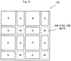
- the stereoscopic pixel may include at least one sub pixel for a color other than red, blue, and green.
- the color of the sub pixel other than red, blue, and green may be at least either yellow or white.
- the first interval and the second interval may be the same interval.
- the sub pixels are arranged such that sub pixels positioned substantially symmetrically with respect to a diagonal line extending from an upper left to a lower right or an upper right to a lower left in the stereoscopic pixel may have the same color.
- the sub pixels in the stereoscopic pixel, may be arranged such that sub pixels positioned substantially point-symmetrically with respect to a specific position in the stereoscopic pixel have the same color.
- the sub pixels may be arranged such that an arrangement order in a predetermined direction of sub pixels for red, blue, and green in one of the pixel for right eye and the pixel for left eye is different from an arrangement order in the predetermined direction of sub pixels for red, blue, and green in the other one.
- At least one sub pixel for each of red, blue, and green may be arranged in a predetermined order in the horizontal direction, and at least one sub pixel for each of red, blue, and green may be arranged in the same order as the predetermined order, in the vertical direction.
- the display device for displaying a stereoscopic image composed of a plurality of viewpoint images corresponding to a plurality of viewpoints.
- the display device includes an image display portion and an image control portion.
- the image display portion has a plurality of stereoscopic pixels each composed of a plurality of viewpoint pixels, the stereoscopic pixels being arranged in a horizontal direction and in a vertical direction.
- the image control portion is configured to control the image display portion.
- Each of the plurality of viewpoint pixels is composed of a plurality of sub pixels that include at least sub pixels for a first basic color and a second basic color that serve as a base for expressing a color.
- the image control portion is configured to perform control for selectively allowing or not allowing color light emission, for sub pixels present at predetermined intervals in the horizontal direction and in the vertical direction.
- the display device for displaying a stereoscopic image composed of a plurality of viewpoint images corresponding to a plurality of viewpoints.
- the display device includes an image display portion and an image control portion.
- the image display portion has a plurality of stereoscopic pixels each composed of a plurality of viewpoint pixels, the stereoscopic pixels being arranged in a horizontal direction and in a vertical direction.
- the image control portion is configured to control the image display portion.
- Each of the plurality of viewpoint pixels is composed of a plurality of sub pixels.
- the stereoscopic pixel includes at least one sub pixel for each of red, blue, and green, the sub pixels being arranged such that sub pixels positioned substantially symmetrically with respect to a diagonal line extending from an upper left to a lower right or an upper right to a lower left in the stereoscopic pixel have the same color.
- the display device for displaying a stereoscopic image composed of a plurality of viewpoint images corresponding to a plurality of viewpoints.
- the display device includes an image display portion and an image control portion.
- the image display portion has a plurality of stereoscopic pixels each composed of a plurality of viewpoint pixels, the stereoscopic pixels being arranged in a horizontal direction and in a vertical direction.
- the image control portion is configured to control the image display portion.
- Each of the plurality of viewpoint pixels is composed of a plurality of sub pixels.
- the stereoscopic pixel includes at least one sub pixel for each of red, blue, and green, the sub pixels being arranged such that sub pixels positioned substantially point-symmetrically with respect to a specific position in the stereoscopic pixel have the same color.
- the display device for displaying a stereoscopic image composed of an image for right eye and an image for left eye.
- the display device includes an image display portion and an image control portion.
- the image display portion has a plurality of stereoscopic pixels each composed of a pixel for right eye and a pixel for left eye, the plurality of stereoscopic pixels being arranged in a horizontal direction and in a vertical direction.
- the image control portion is configured to control the image display portion.
- the pixel for right eye and the pixel for left eye each includes at least one sub pixel for each of red, blue, and green.
- the sub pixels are arranged such that an arrangement order in a predetermined direction of sub pixels for red, blue, and green in one of the pixel for right eye and the pixel for left eye is different from an arrangement order in the predetermined direction of sub pixels for red, blue, and green in the other one.
- an arrangement order in a predetermined direction of sub pixels for red, blue, and green in one of the pixel for right eye and the pixel for left eye may be the same as an arrangement order, in a direction perpendicular to the predetermined direction, of sub pixels for red, blue, and green in the stereoscopic pixel composed of the pixel for right eye and the pixel for left eye.
- the display device for displaying a stereoscopic image composed of a plurality of viewpoint images corresponding to a plurality of viewpoints.
- the display device includes an image display portion and an image control portion.
- the image display portion has a plurality of stereoscopic pixels each composed of a plurality of viewpoint pixels, the stereoscopic pixels being arranged in a horizontal direction and in a vertical direction.
- the image control portion is configured to control the image display portion.
- the stereoscopic pixel at least includes one sub pixel for red, one sub pixel for blue, and two sub pixels for green.
- a first sub pixel for green is located between the sub pixel for red and the sub pixel for blue.
- a second sub pixel for green is located outward of the sub pixel for red and the sub pixel for blue.
- a sum of sizes of the first sub pixel for green and the second sub pixel for green is the same as a size of the sub pixel for red or blue.
- the display device for displaying a stereoscopic image composed of a plurality of viewpoint images corresponding to a plurality of viewpoints.
- the display device includes an image display portion and an image control portion.
- the image display portion has a plurality of stereoscopic pixels arranged in a horizontal direction and in a vertical direction.
- the image control portion is configured to control the image display portion.
- Each of the plurality of stereoscopic pixels is composed of a plurality of regions arranged in the horizontal direction and in the vertical direction, the regions each including a plurality of sub pixels that include at least sub pixels for a first basic color and a second basic color that serve as a base for expressing a color.
- the image control portion is configured to perform control for selectively allowing or not allowing color light emission, on a region-by-region basis, for sub pixels included in the regions present at predetermined intervals in the horizontal direction and in the vertical direction.
- each of the plurality of regions may be a four-row four-column region in the stereoscopic pixel.
- a width of each region for which the control for selectively allowing or not allowing color light emission is performed by the image control portion may be substantially equal to or substantially half a width of each region for which the control for selectively allowing or not allowing color light emission is not performed by the image control portion.
- the display device for displaying a stereoscopic image composed of a plurality of viewpoint images corresponding to a plurality of viewpoints.
- the display device includes an image display portion and an image control portion.
- the image display portion has a plurality of stereoscopic pixels each composed of a plurality of viewpoint pixels, the stereoscopic pixels being arranged in a horizontal direction and in a vertical direction.
- the image control portion is configured to control the image display portion.
- Each of the plurality of viewpoint pixels is composed of a plurality of sub pixels.
- At least one sub pixel for each of red, blue, and green is arranged in a predetermined order in the horizontal direction, and at least one sub pixel for each of red, blue, and green is arranged in the same order as the predetermined order, in the vertical direction.
- the display device for displaying a stereoscopic image composed of an image for right eye and an image for left eye.
- the display device includes an image display portion and an image control portion.
- the image display portion has a plurality of stereoscopic pixels each composed of a pixel for right eye and a pixel for left eye, the plurality of stereoscopic pixels being arranged in a horizontal direction and in a vertical direction.
- the image control portion is configured to control the image display portion.
- the pixel for right eye and the pixel for left eye each includes at least one sub pixel for each of red, blue, and green arranged in the vertical direction.
- a region having a predetermined width is provided between the sub pixel arranged in the vertical direction in the pixel for right eye and the sub pixel arranged in the vertical direction in the pixel for left eye. At least one sub pixel for one of red, blue, and green is located in the region having the predetermined width.
- the image control portion may perform control for allowing or not allowing color light emission, on the sub pixel located in the region having the predetermined width.
- the number of the sub pixel located in the region having the predetermined width may be less than the number of the at least one sub pixel for red, blue, or green arranged in the vertical direction.
- a display device that allows a stereoscopic image to be visible even if a screen is changed from a predetermined orientation, while maintaining a color display quality in a preferred state before and after the change.
- a stereoscopic image display device (hereinafter, simply referred to as a display device) according to the present embodiment displays a stereoscopic image composed of a plurality of viewpoint images corresponding to a plurality of viewpoints.
- the display device includes an image display portion having a plurality of viewpoint pixels arranged in the horizontal direction and the vertical direction, and an image control portion configured to control the image display portion.
- the plurality of viewpoint pixels are each composed of sub pixels arranged in patterns described later.
- the image control portion controls the image display portion so as to sequentially displaying a plurality of viewpoint images along the horizontal direction, using a plurality of "stereoscopic pixels" each of which is composed of, as a unit, a plurality of viewpoint pixels adjacent in the horizontal direction.
- the display device is a plasma display, an organic EL display, a MEMS display, a liquid crystal display, or the like.
- the display device is a liquid crystal display.
- horizontal direction and vertical direction may not strictly mean the horizontal direction and the vertical direction, depending on the way to use the hand-held terminal.
- horizontal direction means a direction in which a line connecting a left eye and a right eye of an observer extends.
- vertical direction means a direction perpendicular to the horizontal direction.
- a horizontally long screen (so-called landscape display) whose long-side direction coincides with (or almost coincides with) the horizontal direction when an observer views the screen is referred to as a "horizontal screen”.
- a vertically long screen (so-called portrait display) whose long-side direction coincides with (or almost coincides with) the vertical direction is referred to as a "vertical screen”.
- the case where the display device is used in a "vertical screen" state is defined as a normal state.
- a stereoscopic image is composed of a left-eye viewpoint image and a right-eye viewpoint image.
- pixels composing a left-eye viewpoint image and pixels composing a right-eye viewpoint image are alternately displayed in the horizontal direction.
- pixels composing a left-eye viewpoint image and pixels composing a right-eye viewpoint image are alternately displayed in a direction that corresponds to the vertical direction when the display device is in a "vertical screen” state. In this case, an observer views the stereoscopic image with the display device turned by 90 degrees.
- images for three or more viewpoints may be used so that a plurality of observers can view the stereoscopic image from different viewpoints.
- the number of viewpoints there is known a technique of allowing, for example, two observers to view a stereoscopic image simultaneously. In this case, at least four viewpoints are assumed (There are right-eye viewpoints and left-eye viewpoints for two persons, i.e., there are four viewpoints in total. There are two positions where the stereoscopic image can be viewed simultaneously).
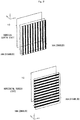
- FIG. 1 is a schematic diagram showing a non-limiting example of the display device 100 according to the first embodiment.
- the display device 100 includes an image display portion 10 and an image separating portion 30.
- the image display portion 10 is composed of a plurality of viewpoint pixels (hereinafter, simply referred to as pixels). Each pixel is composed of sub pixels for red, blue, and green. Inside the image display portion 10, a backlight (not shown) is also provided for radiating light from a back side to the plurality of sub pixels.
- the image separating portion 30 separates image light emitted from pixels (pixels L in the image display portion 10) composing a left-eye viewpoint image (image for left eye), and image light emitted from pixels (pixels R in the image display portion 10) composing a right-eye viewpoint image (image for right eye), from each other.
- the image separating portion 30 is a parallax barrier, a lenticular lens, or the like. In the present embodiment, the image separating portion 30 is a parallax barrier, as an example.
- the image separating portion 30 has a parallax barrier for "vertical screen” (a parallax barrier extending in the vertical direction as seen in a "vertical screen” state), and a parallax barrier for "horizontal screen” (a parallax barrier extending in the horizontal direction as seen in a "vertical screen” state), and is controlled to be switched therebetween as appropriate in accordance with whether the display device is in a "horizontal screen” state or a "vertical screen” state.
- FIG. 2 is a schematic diagram showing a non-limiting example of a concept of control for the image separating portion 30 in the present embodiment. In the example in FIG.
- a parallax barrier 30A for vertical screen and a parallax barrier 30B for horizontal screen are placed, overlapping on each other, at a front surface side of the image display portion 10. Both parallax barriers are disabled by default.
- One of the parallax barriers is enabled as necessary. That is, control is performed so that, in a vertical screen state, the parallax barrier 30A for vertical screen is enabled, and in a horizontal screen state, the parallax barrier 30B for horizontal screen is enabled.
- Each of the plurality of sub pixels composing each pixel includes a transparent pixel electrode (not shown), a transparent common electrode (not shown), and an RGB color filter.
- the transparent pixel electrode and the transparent common electrode are placed being opposed to each other via a liquid crystal (not shown).
- a thin film transistor (not shown) for switching is connected to the transparent pixel electrode. Through switching operation of the thin film transistor, image signal voltage is applied to the transparent pixel electrode, whereby the sub pixel is driven.
- a liquid crystal molecule having an optical anisotropy property and a polarization property is excited due to a potential difference occurring between the transparent pixel electrode and the transparent common electrode.
- a difference in transmittance occurs among liquid crystal molecules in the sub pixels.
- the plurality of sub pixels emit color lights according to their respective transmittances and the colors of the respective color filters, by receiving light from the backlight.
- FIG. 3 is a block diagram showing a non-limiting example of the display device 100 according to the first embodiment. As shown in FIG. 3 , the display device 100 includes the image display portion 10, the image control portion 50, and a determination portion 60.
- the image display portion 10 is composed of a plurality of pixels as described above. Specifically, the image display portion 10 has a plurality of pixels placed in the horizontal direction and the vertical direction.
- a plurality of sub pixels compose one pixel (arrangement of the sub pixels will be described later).
- a plurality of pixels (here, two pixels) adjacent in the horizontal direction compose one stereoscopic pixel.
- each stereoscopic pixel is displayed as a pixel forming a left-eye viewpoint image.
- the other pixel is displayed as a pixel forming a right-eye viewpoint image. That is, left-eye viewpoint images and right-eye viewpoint images are sequentially displayed on a pixel-by-pixel basis along the horizontal direction.
- R denotes red
- G denotes green
- B denotes blue
- the image control portion 50 controls the image display portion 10. Specifically, the image control portion 50 controls the image display portion 10 so as to display a plurality of viewpoint images (left-eye viewpoint image and right-eye viewpoint image) alternately along the horizontal direction, using a plurality of pixels.
- a plurality of viewpoint images left-eye viewpoint image and right-eye viewpoint image
- the image control portion 50 performs control so that only some of the sub pixels composing each pixel are allowed to emit color lights, and the other sub pixels are not allowed to emit color lights.
- the image control portion 50 performs control so that, of the sub pixels arranged in the vertical and horizontal directions, sub pixels at even-numbered locations are not allowed to emit color lights, and sub pixels at odd-numbered locations are allowed to emit color lights.
- a pixel may be divided into a plurality of "regions", and the control for allowing or not allowing color light emission may be performed on a region-by-region basis. In this case, the number of sub pixels located in each region is not limited to one, but a plurality of sub pixels may be located in each region.
- the sub pixels included in each region may be collectively targeted for the color light emission control. That is, in the above control, the control target may be each individual "sub pixel", or may be each region (which can include a plurality of sub pixels). In the following description, basically, an example in which the control target is each individual sub pixel will be described. However, for reference, in an "arrangement pattern 1" described later, an example in which the control target is each region will be also described.
- sub pixels that are "not allowed to emit color lights" in the above control are not allowed to emit color lights no matter what image the display device 100 displays.
- the display device 100 also has the determination portion 60 for determining whether a screen is in a "horizontal screen” state or in a "vertical screen” state as described above (in other words, determining the orientation of the screen or the orientation of the display device 100).
- the determination method a known method may be used.
- the display device 100 may be provided with an acceleration sensor, and the orientation of the display device 100 may be calculated based on a result of detection by the acceleration sensor, whereby whether the screen is in a "horizontal screen” state or in a "vertical screen” state may be determined.
- the determination portion 60 outputs the determination result to the image control portion 50.
- the image control portion 50 performs control for sub pixels as described later, based on the determination result (that is, whether the screen is in a "horizontal screen” state or in a "vertical screen” state) sent from the determination portion. In addition, based on the determination result, the image control portion 50 also performs control for switching between enabling and disabling of the parallax barrier for horizontal screen and the parallax barrier for vertical screen. In the present embodiment, the image control portion 50 switches a display control mode between two modes in accordance with a result outputted from the determination portion, and controls the image display portion 10 in accordance with the mode. Specifically, if the output from the determination portion 60 indicates a "horizontal screen", the image control portion 50 sets the display control mode to a "horizontal display mode".
- the image control portion 50 sets the display control mode to a "vertical display mode”. Then, the image control portion forms a parallax barrier according to the display control mode. That is, in the "horizontal display mode", the image control portion performs control to disable the parallax barrier for vertical screen, and in the "vertical display mode", the image control portion performs control to disable the parallax barrier for horizontal screen.
- the "horizontal display mode” and the “vertical display mode” may be switched by an observer's predetermined operation, for example.
- the "horizontal display mode” and the “vertical display mode” may be switched in accordance with an observer's operation such as operation of a slidable switch for switching between both modes, an operation for setting a screen direction on a predetermined setting screen, or the like.
- sub pixels for three primary colors of RGB are arranged in arrangement patterns described below. As an example, seven arrangement patterns will be described below. Owing to these arrangement patterns and color light emission control described below, in the present embodiment, the amounts of red light, green light, and blue light entering a right eye and a left eye can be made equal both when the screen is viewed in a "vertical screen” state and when the screen is viewed in a "horizontal screen".
- the sub pixels are arranged so that the ratio (proportion) of red, green, and blue in each pixel becomes constant irrespective of whether the screen is viewed horizontally or vertically. As a result, even if an observer is not at an ideal position for stereoscopic viewing, the observer can view a stereoscopic image.
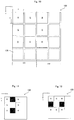
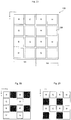
- FIG. 4 is a diagram showing a non-limiting example of arrangement of sub pixels in a stereoscopic pixel 120 according to the first embodiment.
- the arrangement pattern shown in FIG. 4 is referred to as an "arrangement pattern 1".
- the case where the screen is a "vertical screen” is shown.
- the stereoscopic pixel 120 shown in FIG. 4 is composed of two pixels 121 and 122 adjacent in the horizontal direction as described above.
- the pixel 121 is a pixel for right eye
- the pixel 122 is a pixel for left eye. Since FIG. 4 shows the case of "vertical screen” as described above, in the case of "horizontal screen", allocation of the pixel for right eye and the pixel for left eye is changed as appropriate in accordance with turning by 90 degrees.
- the pixel for right eye 121 and the pixel for left eye 122 each include six sub pixels, and a total number of sub pixels included in the stereoscopic pixel 120 is twelve.
- sub pixels are arranged in two columns in the vertical direction (y-axis direction) and in four rows in the horizontal direction (x-axis direction).
- sub pixels are arranged in four columns and four rows. That is, the stereoscopic pixel 120 is configured such that at least four sub pixels can be arranged in each column or each row.
- the number of sub pixels of G is more than the number of sub pixels of R or B.
- a "row” corresponds to arrangement in the x-axis direction (right-left direction) on the screen in a “vertical screen” state
- a “column” corresponds to arrangement in the y-axis direction (up-down direction).
- FIG. 4 in the pixel for right eye 121, first, in a left column (the first column in the stereoscopic pixel 120 as a whole), four sub pixels are arranged in order of R, G, B, then G along the vertical direction (y-axis direction).
- a right column the second column in the stereoscopic pixel 120 as a whole
- one sub pixel of G is located at each position adjacent to the sub pixel of R or B.
- a sub pixel of G is located between a sub pixel of R and a sub pixel of B while the sub pixels of G are not adjacent to each other.
- a vacant region 126 in FIG. 4 , a region indicated by a dotted square) in which no sub pixel is located is present between the sub pixel of G and the sub pixel of G.
- a vacant region 126 is also present in the fourth row of this column.
- the pixel for left eye 122 in a left column (the third column in the stereoscopic pixel 120 as a whole), four sub pixels are arranged in order of B, G, R, then G along the vertical direction. That is, as compared to the left column in the pixel for right eye 121, the order of R and G is reversed.
- a right column in the pixel for left eye 122, as in the above pixel for right eye 121, one sub pixel of G is located at each position adjacent to the sub pixel of R or B.
- a vacant region 126 is present between the sub pixel of G and the sub pixel of G.
- a vacant region 126 is also present in the fourth row in this column.
- a first sub pixel of G i.e., the sub pixel of G in the left column
- a second sub pixel of G i.e., the sub pixel in the right column
- the second sub pixel of G located outward of the sub pixel of R or the sub pixel of B is located between the sub pixel of R and the sub pixel of B.
- the arrangement order of RGB in the first row and the arrangement order of RGB in the first column are the same, i.e., R, G, B, then G. That is, in both the vertical direction and the horizontal direction, the sub pixels are arranged in order of R, G, B, then G (namely, the same order), starting from the sub pixel positioned at the upper left in the stereoscopic pixel 120.
- the number of sub pixels of G is more than the number of sub pixels of R or B. Specifically, the number of R is two, the number of B is two, and the number of G is four.
- the pixel for right eye and the pixel for left eye each include at least one sub pixel for each of red, blue, and green.
- At least one sub pixel for each of R, G, and B is included in the first column and in the third column, but only sub pixels of G are located in the second column and in the fourth column.
- at least one sub pixel for each of R, G, and B is included in the first row and in the third row, and only sub pixels of G are located in the second row and in the fourth row.
- Such sub pixels in the even-numbered columns and in the even-numbered rows are targets of control for allowing or not allowing color light emission as described later.
- a sub pixel for a color that is not targeted for the later-described control for allowing or not allowing color light emission is not located in the even-numbered column or the even-numbered row.
- the horizontal width of a sub pixel will be described.
- the widths of sub pixels in the horizontal direction as seen from an observer are set such that the ratio of the horizontal width of each sub pixel of R and B and the horizontal width of each sub pixel of G is 2 : 1.
- the ratio of the horizontal widths is not limited thereto.
- the ratio of the horizontal width of each sub pixel of R and B and the horizontal width of each sub pixel of G may be set at 1 : 1 (for example, an arrangement pattern 2 described later).
- other ratios may be used.
- the ratio of the widths of sub pixels in the horizontal direction as seen from an observer may differ between a vertical screen state and a horizontal screen state (for example, an arrangement pattern 5 described later).
- each sub pixel of R and B has the same area.
- An area of a sub pixel of G is half the area of the sub pixel of R or B.
- each sub pixel of R and B is a square having a side with a length of p.
- a sub pixel of G is a rectangle having a long side with the length of p and a short side with half (p/2) the length of p (it is noted that, in a horizontal screen state, the short side of the sub pixel of G is parallel to the x axis (horizontal direction)).
- the area of a sub pixel of G is half the area of a sub pixel of R or B.
- a sum of the areas of two sub pixels of G is equal to the area of a sub pixel of R or B.
- the number of sub pixels of G is twice the total number of sub pixels of R and B. Therefore, in one pixel, areas occupied by the respective sub pixels of R, G, and B are the same.
- an area of the vacant region 126 is 1/4 of the area of a sub pixel of R or B.
- the sub pixels in the arrangement pattern 1 are arranged such that sub pixels positioned substantially line-symmetrically with respect to a diagonal line extending from the upper left to the lower right in the stereoscopic pixel 120 have the same color.
- the image control portion 50 performs control for allowing or not allowing any sub pixel of G in each pixel in accordance with whether the screen is a "vertical screen” or a "horizontal screen” (a determination result from the determination portion 60). Specifically, in the case of "vertical screen”, controls is performed so that, in the horizontal direction, sub pixels at first intervals are not allowed to emit color lights, and in the vertical direction, sub pixels at second intervals are allowed to emit color lights. On the other hand, in the case of "horizontal screen”, controls is performed so that, in the vertical direction, sub pixels at the second intervals are not allowed to emit color lights, and in the horizontal direction, sub pixels at the first intervals are allowed to emit color lights.
- control is performed so that, in the stereoscopic pixel 120, sub pixels located in even-numbered rows or columns (corresponding to the first intervals and the second intervals) starting from the sub pixel at the upper left are selectively allowed or not allowed to emit color lights in accordance with whether or not the screen is a vertical screen or a horizontal screen.
- control is performed so that, in the arrangement order of the sub pixels, even-numbered sub pixels are selectively allowed or not allowed to emit color lights.
- control is performed such that sub pixels present in a column in which sub pixels are arranged in the vertical direction as seen from observer's eyes (a “column” as seen from the observer's viewpoint, or an array along a longitudinal direction of a parallax barrier used in the present screen state) and in which sub pixels of R and B are not present, are not allowed to emit color lights.
- FIG. 5 is a diagram showing a non-limiting example of a color light emission state of the stereoscopic pixel 120 in the case where the image control portion 50 operates in a "vertical display mode".
- sub pixels of G located in the second column and the fourth column are not allowed to emit color lights (Sub pixels in filled areas do not emit color lights. The same applies hereinafter.). This can be considered to be control of not allowing sub pixels in even-numbered columns to emit color lights.
- the stereoscopic pixel 120 only sub pixels of R, G, B, and then G in the first column and sub pixels of B, G, R, and then G in the third column (corresponding to the first column in the pixel for left eye 122) emit color lights.
- control is performed so that sub pixels of G at even-numbered locations as counted from the left end of the stereoscopic pixel 120 are not allowed to emit color lights.
- not allowing even-numbered columns to emit color lights generates some regions that do not emit color lights in the stereoscopic pixel 120. This enables an observer to view a stereoscopic image even if the observer is not at an ideal position for stereoscopic viewing.
- the color light emission state is as shown in FIG. 6 .
- the screen is in a "horizontal screen” state, a screen obtained by turning right or left the screen shown in FIG. 6 by 90 degrees is actually seen by an observer.
- the color light emission control shown in FIG. 6 as compared to the case in FIG. 5 , only sub pixels in the first row and the third row which include sub pixels of R and B are allowed to emit color lights.
- sub pixels (in FIG. 6 , sub pixels of G) in the second row and the fourth row, i.e., in even-numbered rows as counted from above are controlled to be not allowed to emit color lights.
- the stereoscopic pixel 120 sub pixels of G at even-numbered locations as counted from above are controlled to be not allowed to emit color lights.
- the sub pixel of R and the sub pixel of B in the first column are included in the pixel for right eye 121 in a vertical screen state. Therefore, in a vertical screen state, those sub pixels are controlled as pixels for right eye.
- the case where the screen is turned left by 90 degrees will be considered ( FIG. 6 is turned left by 90 degrees).
- the sub pixel of R is included in the pixel for right eye 121 as in the case of vertical screen state, but the sub pixel of B is included in the pixel for left eye. Therefore, the sub pixel of B is controlled as a pixel for left eye in a horizontal screen state (in the case where the screen is turned left by 90 degrees).
- color light emission control for the sub pixel of B in a horizontal screen state is the same as color light emission control for a sub pixel of B in the third column in a vertical screen state.
- the case where the screen is turned right by 90 degrees from a vertical screen state will be considered ( FIG. 6 is turned right by 90 degrees).
- the sub pixel of R is included in a pixel for left eye, and the sub pixel of B is still in a pixel for right eye. Therefore, in a horizontal screen state (in the case where the screen is turned right by 90 degrees), the sub pixel of R is controlled as a pixel for left eye.
- color light emission control for the sub pixel of R in a horizontal screen state is the same as color light emission control for a sub pixel of R in the third column in a vertical screen state.
- the sub pixel of B is switched between a role as a pixel for right eye and a role as a pixel for left eye, but the sub pixel of R is not changed in its role between before and after the turning.
- the sub pixel of R is switched between a role as a pixel for right eye and a role as a pixel for left eye, but the sub pixel of B is not changed in its role between before and after the turning.
- the image control portion 50 performs control so that sub pixels in even-numbered columns or rows in the arrangement order starting from the sub pixel located at the upper left of the stereoscopic pixel 120 are selectively allowed or not allowed to emit color lights in accordance with whether in the horizontal display mode or in the vertical display mode.
- control is performed so that, in the vertical display mode, at least one of the sub pixels of G is not allowed to emit color light, and in the horizontal display mode, at least the other one of the sub pixels of G is not allowed to emit color light.
- the sub pixels of G that are allowed (not allowed) to emit color lights differ between the vertical display mode and the horizontal display mode.
- At least one sub pixel for each of R, G, and B is allowed to emit color light in both the vertical display mode and the horizontal display mode.
- the sub pixels included in the stereoscopic pixel 120 are arranged as shown in FIG. 4 .
- the amounts of lights of R, G, and B entering both eyes of an observer increase or decrease in the same rate when the position of the observer's viewpoint is changed.
- the positions of both eyes of an observer slightly shift leftward from positions appropriate for recognizing stereoscopic display.
- the parallax barrier 30A for vertical screen partially overlaps on left ends of sub pixels in the first and third columns as seen from an observer, as shown in FIG. 7 .
- the parallax barrier 30B for horizontal screen partially overlaps on left ends of sub pixels in the first and third columns along the x-axis direction in FIG. 8 (if the screen is taken as a vertical screen, the parallax barrier 30B for horizontal screen overlaps on upper ends in the first and third rows).
- R, G, and B decrease at an equal rate.
- FIG. 5 since areas in the second and fourth columns in which sub pixels of G are located are present, even if an observer is not at an ideal position for stereoscopic viewing, the observer can clearly view a stereoscopic image.
- FIG. 9 is a diagram showing a non-limiting example of a concept in which the color light emission control is performed on a region basis in the arrangement pattern 1.
- the stereoscopic pixel 120 is divided into 4 ⁇ 4 regions.
- the size ratio of the regions and the arrangement layout of the regions comply with the arrangement pattern 1. That is, a region A1 and a region C3 in FIG. 9 correspond to the sub pixels of R in FIG.
- a region A3 and a region C1 correspond to the sub pixels of B in FIG. 4 .
- a region A2, a region A4, a region B1, a region B3, a region C2, a region C4, a region D1, and a region D3 correspond to the sub pixels of G in FIG. 4 .
- a region B2, a region B4, a region D2, and a region D4 correspond to the vacant regions 126 in FIG. 4 (that is, there are no sub pixels located in those regions).
- the number of sub pixels located in each region is not limited to one, but a plurality of sub pixels may be included in each region. Colors of sub pixels located in the respective regions also comply with the arrangement pattern 1.
- each of the region A1 and the region C3, a plurality of sub pixels for only R are located.
- control is performed so that the sub pixels located in the region B1, the region B3, the region D1, and the region D3 in FIG. 9 are not allowed to emit color lights.
- control is performed so that the sub pixels located in the region A2, the region C2, the region A4, and the region C4 are not allowed to emit color lights.
- sub pixels included in each region have the same color (one color).
- sub pixels included in each region may have two or more colors. That is, a certain region may include sub pixels having a plurality of colors.
- each sub pixel of R and B have the same length (that is, a square), and the vertical side and the horizontal side of each sub pixels of G have different lengths (have a long side and a short side).
- the lengths of these sides are not limited to the above example, but may be any lengths.
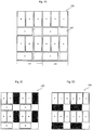
- FIG. 10 an arrangement pattern shown in FIG. 10 is referred to as an "arrangement pattern 2". Also in FIG. 10 , the case where the screen is a "vertical screen" is shown.
- the number of sub pixels included in the stereoscopic pixel 120 is eight in total. That is, a total number of sub pixels per one stereoscopic pixel is reduced as compared to the arrangement pattern 1.
- the breakdown there are two sub pixels for each of R and B, and there are four sub pixels of G.
- the number of sub pixels of G is more than the number of sub pixels of R or B.
- one sub pixel for each color is located in order of R, G, then B in the vertical direction.
- a vacant region 126 is present under the sub pixel of B.
- one sub pixel of G is located at each position adjacent to the sub pixel of R or B.
- a vacant region 126 is also present at a position (a position not adjacent to the sub pixel of R or B) under each sub pixel of G.
- one sub pixel for each color is located in order of B, G, then R in the vertical direction. This order is different (in this example, reverse order) from the order of sub pixels in the left column in the pixel for right eye 121.
- a vacant region 126 is present under the sub pixel of R.
- vacant regions 126 are present in the entire right column (the fourth column in the stereoscopic pixel 120).
- the sub pixels are arranged in order of R, G, then B (the same order) in the rightward direction and in the downward direction. That is, starting from the sub pixel located at the upper left in the stereoscopic pixel, the sub pixels of R, G, and B are arranged in the same order in the horizontal direction and in the vertical direction.
- the stereoscopic pixel 120 as a whole, it can also be said that eight sub pixels are arranged in an annular shape.
- the eight sub pixels arranged in this way are located on the upper left side in the stereoscopic pixel 120.
- sub pixels positioned substantially line-symmetrically with respect to a diagonal line extending from the upper left to the lower right in the stereoscopic pixel 120 have the same color.
- a vertical side and a horizontal side of each sub pixel located in the stereoscopic pixel 120 have the same length of p (i.e., a square), and the areas thereof are the same.
- the widths of the sub pixels in the horizontal direction as seen from an observer are such that the ratio of the horizontal width of each sub pixel of R and B and the horizontal width of the sub pixel of G is 1 : 1.
- Control for the stereoscopic pixel 120 using the arrangement pattern 2 is basically the same as in the arrangement pattern 1. That is, control is performed so that even-numbered sub pixels (in FIG. 10 , sub pixels of G) in the arrangement order starting from the sub pixel located at the upper left of the stereoscopic pixel 120 are selectively allowed or not allowed to emit color lights in accordance with whether in the horizontal display mode or in the vertical display mode.
- FIGS. 11 and 12 show a non-limiting example of the control for the stereoscopic pixel 120 in the case of the arrangement pattern 2.
- FIG. 11 shows a color light emission state of the stereoscopic pixel 120 in the "vertical display mode”.
- FIG. 12 shows a color light emission state of the stereoscopic pixel 120 in the "horizontal display mode”.
- control is performed so that, starting from the sub pixel located at the upper left in the stereoscopic pixel 120, sub pixels (sub pixels located in even-numbered columns) at even-numbered locations from left in the arrangement order are not allowed to emit color lights.
- sub pixels in the second column from left are not allowed to emit color lights.
- control is performed so that, starting from the sub pixel located at the upper left in the stereoscopic pixel 120, sub pixels (sub pixels located in even-numbered rows) at even-numbered locations from above in the arrangement order are not allowed to emit color lights.
- sub pixels in the second row from above are not allowed to emit color lights. That is, as in the arrangement pattern 1, the image control portion 50 performs control so that even-numbered sub pixels in the arrangement order starting from the sub pixel located at the upper left of the stereoscopic pixel 120 are selectively allowed or not allowed to emit color lights in accordance with whether in the vertical display mode or in the horizontal display mode.
- a vacant region 126 is present at the center, and collection of eight sub pixels annularly located around the vacant region 126 is located to the upper left side of the stereoscopic pixel 120.
- the collection of the sub pixels may be located to the upper right side of the stereoscopic pixel 120, or may be located to the lower left side or lower right side.
- columns or rows targeted for the control for allowing or not allowing color light emission are changed. That is, columns or rows targeted for the control may be changed as appropriate so that similar control as shown in FIG. 11 and FIG. 12 is performed for the eight sub pixels that are annularly located.
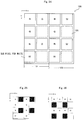
- FIG. 13 an arrangement pattern shown in FIG. 13 is referred to as an "arrangement pattern 3". Also in FIG. 13 , the case where the screen is a "vertical screen" is shown.
- the number of sub pixels included in the stereoscopic pixel 120 is eight in total. Regarding the breakdown, there are two sub pixels for each of R and B, and there are four sub pixels of G. That is, as in the arrangement patterns 1 and 2, the number of sub pixels of G is more than the number of sub pixels of R or B.
- one sub pixel for each color is located in order of R, G, then B in the vertical direction.
- a vacant region 126 is present under the sub pixel of B.
- one sub pixel of G is located at a position adjacent to the sub pixel of R. The entire region under the sub pixel of G is vacant regions 126.
- a sub pixel of B is located at the uppermost position. Under this, a sub pixel of R is located via a vacant region 126 corresponding to one sub pixel. Under this, a sub pixel of G is located. In the right column in the pixel for left eye 122, a sub pixel of G is located at a position adjacent to the sub pixel of R in the left column.
- a sub pixel of R is located at the upper left, and starting from this, sub pixels are arranged in the same order (R, G, then B) in the vertical direction (downward direction) and in the horizontal direction (rightward direction).
- This arrangement is also considered to be a reversed L shape.
- three sub pixels are located in a reversed L shape.
- sub pixels positioned substantially line-symmetrically with respect to a diagonal line extending from the upper left to the lower right in the stereoscopic pixel 120 have the same color.
- a vertical side and a horizontal side of each sub pixel located in the stereoscopic pixel have the same length, and the areas thereof are the same.
- the widths of the sub pixels in the horizontal direction as seen from an observer are such that the ratio of the horizontal width of each sub pixel of R and B and the horizontal width of the sub pixel of G is 1 : 1.
- Control for the stereoscopic pixel 120 using the arrangement pattern 3 is also basically the same as in the arrangement pattern 1. That is, control is performed so that even-numbered sub pixels (in FIG. 13 , sub pixels of G) in the arrangement order starting from the sub pixel located at the upper left of the stereoscopic pixel 120 are selectively allowed or not allowed to emit color lights in accordance with whether in the vertical display mode or in the horizontal display mode.
- FIGS. 15 and 16 show a non-limiting example of the control for the stereoscopic pixel 120 in the case of the arrangement pattern 3.
- FIG. 15 shows a color light emission state of the stereoscopic pixel 120 in the "vertical display mode”.
- FIG. 16 shows a color light emission state of the stereoscopic pixel 120 in the "horizontal display mode”.
- control is performed so that, starting from the sub pixel located at the upper left in the stereoscopic pixel 120, even-numbered sub pixels in the horizontal direction, i.e., in the example in FIG. 15 , sub pixels of G in the second column and the fourth column from left are not allowed to emit color lights.
- control is performed so that, starting from the sub pixel located at the upper left in the stereoscopic pixel 120, even-numbered sub pixels in the vertical direction in the arrangement order, i.e., in the example in FIG. 16 , sub pixels of G in the second row and the fourth row from above are not allowed to emit color lights.
- the same effect as in the arrangement pattern 1 can be obtained. That is, in both cases of “vertical screen” and “horizontal screen", the amounts of lights of R, G, and B entering both eyes of an observer increase or decrease in the same rate when the position of the observer's viewpoint is changed.
- FIG. 17 an arrangement pattern shown in FIG. 17 is referred to as an "arrangement pattern 4". Also in FIG. 17 , the case where the screen is a "vertical screen" is shown.
- the number of sub pixels included in the stereoscopic pixel 120 is eight in total. Regarding the breakdown, there are two sub pixels for each of R and B, and there are four sub pixels of G. As in the above arrangement patterns, the number of sub pixels of G is more than the number of sub pixels of R or B.
- one sub pixel for each color is located in order of R, G, then B in the vertical direction.
- a vacant region 126 is present under the sub pixel of B.
- one sub pixel of G is located at each position adjacent to the sub pixel of R or B.
- Vacant regions 126 are also present under the sub pixels of G.
- a sub pixel of B is located at the uppermost position. Under this, a sub pixel of R is located via a vacant region 126 corresponding to one sub pixel. Under this, a sub pixel of G is located. The entire right column in the pixel for left eye 122 is vacant regions 126.
- the arrangement order (in the horizontal direction) of sub pixels in the third row is a reverse order (different order) of the arrangement order of sub pixels in the first row.
- a vertical side and a horizontal side of each sub pixel located in the stereoscopic pixel have the same length, and the areas thereof are the same. Therefore, also in the arrangement pattern 4, in both a vertical screen state and a horizontal screen state, the widths of the sub pixels in the horizontal direction as seen from an observer are such that the ratio of the horizontal width of each sub pixel of R and B and the horizontal width of the sub pixel of G is 1 : 1.
- Control for the stereoscopic pixel 120 using the arrangement pattern 4 is also the same as in the above arrangement patterns. That is, control is performed so that even-numbered sub pixels (in FIG. 17 , sub pixels of G) in the arrangement order starting from the sub pixel located at the upper left of the stereoscopic pixel 120 are selectively allowed or not allowed to emit color lights in accordance with whether in the vertical display mode or in the horizontal display mode.
- FIGS. 18 and 19 show a non-limiting example of the control for the stereoscopic pixel 120 in the case of the arrangement pattern 4.
- FIG. 18 shows a color light emission state of the stereoscopic pixel 120 in the "vertical display mode”.
- FIG. 19 shows a color light emission state of the stereoscopic pixel 120 in the "horizontal display mode”.
- control is performed so that, starting from the sub pixel located at the upper left in the stereoscopic pixel 120, even-numbered sub pixels in the horizontal direction, i.e., in FIG. 18 , the sub pixels of G in the second column from left are not allowed to emit color lights.
- control is performed so that, starting from the sub pixel located at the upper left in the stereoscopic pixel 120, even-numbered sub pixels in the vertical direction in the arrangement order, i.e., in FIG. 19 , sub pixels of G in the second row and the fourth row from above are not allowed to emit color lights.
- each side (width) of sub pixels that are allowed to emit color lights and the length of each side (width) of sub pixels that are not allowed to emit color lights are the same.
- FIG. 20 an arrangement pattern shown in FIG. 20 is referred to as an "arrangement pattern 5". Also in FIG. 20 , the case where the screen is a "vertical screen" is shown.
- the number of sub pixels included in the stereoscopic pixel 120 is sixteen in total.
- the number of sub pixels of G is more than the number of sub pixels of R or B.
- each of the pixel for right eye 121 and the pixel for left eye 122 there are three columns and four rows.
- a sub pixel of B is located at the first column and the first row.
- a sub pixel of R is located at the adjacent location on the right, i.e., at the second column and the first row.
- a sub pixel of G is located at the adjacent location on the right, i.e., at the third column and the first row.
- a sub pixel of G is located across the first and second columns.
- a vacant region 126 is present.
- a sub pixel of R is located at the first column and the third row.
- a sub pixel of B is located at the adjacent location on the right, i.e., at the second column and the third row.
- a sub pixel of G is located at the adjacent location on the right, i.e., at the third column and the third row. That is, as compared to the arrangement in the first row, the locations of R and B are reversed.
- a sub pixel of G is located across the first and second columns.
- a vacant region 126 is present.
- the sub pixels of R, B, and G have the same size, and the shapes thereof are rectangles.
- the length of a long side of these rectangles is twice as long as the length of a short side.
- the sub pixels are located with their long sides along the vertical direction.
- the sub pixels are located with their long sides along the horizontal direction.
- control for the stereoscopic pixel 120 using the arrangement pattern 5 will be described. Also in this arrangement pattern, control for selectively allowing or not allowing sub pixels (of G) to emit color lights in accordance with whether in the horizontal display mode or in the vertical display mode. However, in this arrangement pattern, since the number of rows and the number of columns are different, the arrangement order of sub pixels that are control targets is different between in the column direction (vertical direction) and in the row direction (horizontal direction).
- FIGS. 21 and 22 show a non-limiting example of the control for the stereoscopic pixel 120 in the case of the arrangement pattern 5.
- FIG. 21 shows a color light emission state of the stereoscopic pixel 120 in the "vertical display mode”.
- FIG. 22 shows a color light emission state of the stereoscopic pixel 120 in the "horizontal display mode”.
- control is performed so that, starting from the sub pixel located at the upper left in the stereoscopic pixel 120, sub pixels (of G) at the third and sixth locations from left in the arrangement order are not allowed to emit color lights.
- control is performed so that, starting from the sub pixel located at the upper left in the stereoscopic pixel 120, sub pixels (of G) at the second and fourth locations from above in the arrangement order are not allowed to emit color lights. That is, in the "vertical display mode", sub pixels that are targets of the color light emission control are present at every third column, and in the "horizontal display mode", sub pixels that are targets of the color light emission control are present at every second row. Thus, the interval between sub pixels that are targets of the color light emission control is different between the vertical display mode and the horizontal display mode.
- sub pixels for three primary colors of RGB are arranged in the above-described patterns, and the above-described color light emission control is performed. That is, sub pixels for one color of R, G, and B, the number of which is larger than the numbers of sub pixels for the other colors, are arranged at even-numbered locations in the arrangement order (specific examples of such arrangement patterns are as described above). Those sub pixels at the even-numbered locations are selectively subjected to the color light emission control.
- targets of such selective color light emission control are sub pixels of G, while sub pixels of R and B emit color lights in both cases of "vertical screen” and "horizontal screen".
- the amounts of lights of R, G, and B entering both eyes of an observer can be increased or decreased in the same rate in both cases of vertical screen and horizontal screen.
- a region having a predetermined width is provided between vertically arranged sub pixels for right eye and horizontally arranged sub pixels for left eye, and a sub pixel that is a target of control for allowing or not allowing color light emission is located in the region having the predetermined width.
- the sub pixels that are arranged at even-numbered locations in the arrangement order and targeted for the selective color light emission control may be sub pixels of R or B.
- sub pixels targeted for the selective color light emission control may be any one of R, G, and B. No matter what color is employed as the control target, the same effect as described above can be obtained.
- the arrangement order of sub pixels of RGB is not limited to the orders shown in the above arrangement patterns, but may be any order.
- the arrangement pattern 1 from the upper left of the stereoscopic pixel 120, sub pixels are arranged in order of R, G, B, then G in the vertical direction.
- the sub pixels may be arranged in order of B, G, R, then G (in this case, an arrangement order in the third column is R, G, B, then G in the vertical direction).
- the number of sub pixels is two for R, two for B, and eight for G.
- the number of sub pixels may be eight for R, two for B, and two for G (namely, R and G may be replaced with each other in the arrangement pattern 1). That is, the arrangement order of sub pixels of RGB may be any order.
- a color of sub pixels for which control for allowing or not allowing color light emission may be any color.
- sub pixels for only one color are targeted for the selective color light emission control.
- sub pixels for two colors may be targeted for the selective color light emission control.
- FIG. 23 shows an example in which sub pixels for two colors, i.e., sub pixels of R and G are targeted for the selective color light emission control, on the basis of the arrangement pattern 1. That is, in each of even-numbered columns and even-numbered rows, one sub pixel for each of R and G is located. As for odd-numbered columns or odd-numbered rows, for example, in the first column, sub pixels are arranged in order of R, G, B, then G as in the arrangement pattern 1.
- the third column unlike the arrangement pattern 1, sub pixels are arranged in order of B, R, G, then R. In other words, R and G are replaced with each other in the third column in the arrangement pattern 1. Even in the case of performing the above-described selective color light emission control using such an arrangement pattern, the same effect as described above can be obtained.
- Configurations other than a configuration relevant to the sub pixels of W and the arrangement pattern of sub pixels in the stereoscopic pixel 120, i.e., the hardware configuration and the like of the display device 100 are basically the same as in the first embodiment. Therefore, mainly the arrangement pattern of sub pixels in the stereoscopic pixel 120 using RGBW will be described below.
- FIG. 24 is a diagram showing a non-limiting example of arrangement of sub pixels in the stereoscopic pixel 120 according to the second embodiment.
- an arrangement pattern shown in FIG. 24 is referred to as an "arrangement pattern 6".
- the case where the screen is a "vertical screen” is shown.
- the stereoscopic pixel 120 shown in FIG. 24 is composed of, as in the first embodiment, two pixels adjacent to each other in the horizontal direction, that is, a pixel for right eye 121 and a pixel for left eye 122.
- the arrangement pattern 6 there are six sub pixels included in each of the pixel for right eye 121 and the pixel for left eye 122, and the number of sub pixels included in the stereoscopic pixel 120 is twelve in total.
- This arrangement pattern is similar to the arrangement pattern 2 in the first embodiment, and corresponds to a pattern in which four sub pixels of W are located outside the annular pattern of sub pixels in the arrangement pattern 2.
- sub pixels of W are additionally located in rows and columns where sub pixels of R and B are present in the arrangement pattern 2. That is, sub pixels of W are located at right ends in the first and third rows.
- sub pixels of W are also located at lower ends in the first and third columns. In other words, sub pixels of W are located at positions that are adjacent to a sub pixel of R or B and are not adjacent to a sub pixel of G.
- sub pixels are arranged in order of R, G, B, then W (in the same order) in the rightward direction and in the downward direction.
- sub pixels positioned substantially line-symmetrically with respect to a diagonal line extending from the upper left to the lower right in the stereoscopic pixel have the same color.
- sub pixels located substantially point-symmetric with respect to a specific position in the stereoscopic pixel have the same color.
- a vertical side and a horizontal side of each sub pixel located in the stereoscopic pixel 120 have the same length, and the areas thereof are the same. Therefore, in the arrangement pattern 6, in both a vertical screen state and a horizontal screen state, the widths of the sub pixels in the horizontal direction as seen from an observer are such that the ratio of the horizontal width of each sub pixel of R and B and the horizontal width of the sub pixel of G is 1 : 1.
- Control for the stereoscopic pixel 120 using the arrangement pattern 6 is basically the same as the control in the first embodiment.
- FIGS. 25 and 26 show a non-limiting example of the control for the stereoscopic pixel 120 in the case of the arrangement pattern 6.
- FIG. 25 shows a color light emission state of the stereoscopic pixel 120 in the "vertical display mode”.
- FIG. 26 shows a color light emission state of the stereoscopic pixel 120 in the "horizontal display mode”.
- control is performed so that, starting from the sub pixel located at the upper left in the stereoscopic pixel 120, sub pixels along the vertical direction at even-numbered locations from left in the arrangement order are not allowed to emit color lights.
- control is performed so that sub pixels of G in the second column from left and sub pixels of W in the fourth column from left are not allowed to emit color lights.
- control is performed so that, starting from the sub pixel located at the upper left in the stereoscopic pixel 120, sub pixels along the horizontal direction at even-numbered locations from above are not allowed to emit color lights.
- control is performed so that sub pixels of G in the second row from above and sub pixels of W in the fourth row from above are not allowed to emit color lights. That is, as in the arrangement pattern 1 etc., the image control portion 50 performs control so that even-numbered sub pixels in the arrangement order starting from the sub pixel located at the upper left of the stereoscopic pixel 120 are selectively allowed or not allowed to emit color lights in accordance with whether in the horizontal display mode or in the vertical display mode.
- the length of each side (width) of sub pixels that are allowed to emit color lights and the length of each side (width) of sub pixels that are not allowed to emit color lights are the same.
- the same effect as in the arrangement pattern 1 can be obtained. That is, in both cases of “vertical screen” and “horizontal screen", the amounts of lights of R, G, B, and W entering both eyes of an observer increase or decrease in the same rate when the position of the observer's viewpoint is changed.
- FIG. 27 an arrangement pattern shown in FIG. 27 is referred to as an "arrangement pattern 7". Also in FIG. 27 , the case where the screen is a "vertical screen" is shown.
- the arrangement pattern 7 shown in FIG. 27 is obtained by adding four sub pixels of W in the arrangement pattern 4 of the first embodiment. Specifically, the arrangement pattern 7 is obtained by locating sub pixels of W under a sub pixel of B in the first column, at the second row in the third column, and at the first and third rows in the fourth column in the arrangement pattern 4 (all the sub pixels of W are adjacent to a sub pixel of R or B). The sizes of sub pixels are the same. Therefore, also in the arrangement pattern 7, in both a vertical screen state and a horizontal screen state, the widths of the sub pixels in the horizontal direction as seen from an observer are such that the ratio of the horizontal width of each sub pixel of R and B and the horizontal width of the sub pixel of G is 1 : 1.
- sub pixels are arranged in order of R, G, B, then W (in the same order) in the rightward direction and in the downward direction.
- FIGS. 28 and 29 show a non-limiting example of the control for the stereoscopic pixel 120 in the case of the arrangement pattern 7.
- FIG. 28 shows a color light emission state of the stereoscopic pixel 120 in the "vertical display mode”.
- FIG. 29 shows a color light emission state of the stereoscopic pixel 120 in the "horizontal display mode”.
- control is performed so that, starting from the sub pixel located at the upper left in the stereoscopic pixel 120, even-numbered sub pixels in the horizontal direction, i.e., in the example in FIG.
- sub pixels of G in the second column from left and sub pixels of W in the fourth column from left are not allowed to emit color lights.
- control is performed so that, starting from the sub pixel located at the upper left in the stereoscopic pixel 120, even-numbered sub pixels in the vertical direction in the arrangement order, i.e., in the example in FIG. 29 , sub pixels of G and W in the second and fourth rows from above are not allowed to emit color lights.
- FIG. 30 An arrangement pattern shown in FIG. 30 is referred to as an "arrangement pattern 8". Also in FIG. 30 , the case where the screen is a "vertical screen" is shown.
- the arrangement pattern 8 shown in FIG. 30 is obtained by adding four sub pixels of W in the arrangement pattern 3. Specifically, the arrangement pattern 8 is obtained by locating sub pixels of W at four vacant regions 126 present on a diagonal line extending from the upper right to the lower left in the arrangement pattern 3. The sizes of sub pixels are the same. Therefore, also in the arrangement pattern 8, in both a vertical screen state and a horizontal screen state, the widths of the sub pixels in the horizontal direction as seen from an observer are such that the ratio of the horizontal width of each sub pixel of R and B and the horizontal width of the sub pixel of G is 1 : 1.
- sub pixels are arranged in order of R, G, B, then W in the rightward direction and in the downward direction.
- FIGS. 31 and 32 show a non-limiting example of the control for the stereoscopic pixel 120 in the case of the arrangement pattern 8.
- FIG. 31 shows a color light emission state of the stereoscopic pixel 120 in the "vertical display mode”.
- FIG. 32 shows a color light emission state of the stereoscopic pixel 120 in the "horizontal display mode”.
- control is performed so that, starting from the sub pixel located at the upper left in the stereoscopic pixel 120, even-numbered sub pixels in the horizontal direction, i.e., in the example in FIG.
- sub pixels of G and W in the second and fourth columns from left are not allowed to emit color lights.
- control is performed so that, starting from the sub pixel located at the upper left in the stereoscopic pixel 120, even-numbered sub pixels in the vertical direction in the arrangement order, i.e., in the example in FIG. 32 , sub pixels of G and W in the second and fourth rows from above are not allowed to emit color lights.
- FIG. 33 An arrangement pattern shown in FIG. 33 is referred to as an "arrangement pattern 9". Also in FIG. 33 , the case where the screen is a "vertical screen" is shown.
- the arrangement pattern 9 shown in FIG. 33 is similar to the arrangement pattern 5 of the first embodiment. Specifically, the arrangement pattern 9 is obtained by adding two sub pixels of W in the arrangement pattern 5. The size of the sub pixels of W is the same as those of the sub pixels of R and B. The sub pixels of W are located, adjacent to sub pixels of R or B, in the fourth column in the arrangement pattern 5.
- control for the stereoscopic pixel 120 using the arrangement pattern 9 will be described. Basically, as in the arrangement patterns described above, control is performed so that even-numbered sub pixels (in FIG. 33 , sub pixels of G) in the arrangement order starting from the sub pixel located at the upper left of the stereoscopic pixel 120 are selectively allowed or not allowed to emit color lights in accordance with whether in the "vertical display mode" or in the "horizontal display mode".
- FIGS. 34 and 35 show a non-limiting example of the control for the stereoscopic pixel 120 in the case of the arrangement pattern 9.
- FIG. 34 shows a color light emission state of the stereoscopic pixel 120 in the "vertical display mode”.
- FIG. 35 shows a color light emission state of the stereoscopic pixel 120 in the "horizontal display mode”.
- control is performed so that, starting from the sub pixel located at the upper left in the stereoscopic pixel 120, even-numbered sub pixels in the horizontal direction, i.e., in the example in FIG. 34 , sub pixels of G in the second column from left and sub pixels of W in the fourth column from left are not allowed to emit color lights.
- control is performed so that, starting from the sub pixel located at the upper left in the stereoscopic pixel 120, even-numbered sub pixels in the vertical direction in the arrangement order, i.e., in the example in FIG. 35 , sub pixels of G in the second row and the fourth row from above are not allowed to emit color lights.
- the sub pixels of W are controlled so as to emit color lights in a "horizontal screen” state and so as not to emit color lights in a "vertical screen” state, unlike the arrangement patterns 6 to 8.
- the sub pixels of R, G, and B the same effect as in the above arrangement patterns can be obtained.
- the following control may be performed. That is, a correspondence relationship between RGB and RGBW may be set in advance, and color light emission of RGBW may be controlled in accordance with the correspondence relationship. For example, a correspondence relationship of values of R, G, B, and W between the case where white is expressed by only RGB and the case where white is expressed by RGBW may be set in advance, and control based on the correspondence relationship may be performed.
- FIG. 36 An arrangement pattern shown in FIG. 36 is referred to as an "arrangement pattern 10". Also in FIG. 36 , the case where the screen is a "vertical screen" is shown.
- the arrangement pattern 10shown in FIG. 36 is similar to the arrangement pattern 9. Specifically, the arrangement pattern 10is obtained by reversing the positions of sub pixels of G and W in the third row in the arrangement pattern 9. The other part is the same as in the arrangement pattern 9.
- Control for the stereoscopic pixel 120 using the arrangement pattern 10 is also the same as in the arrangement pattern 9. That is, control is performed so that even-numbered sub pixels (in FIG. 36 , sub pixels of G) in the arrangement order starting from the sub pixel located at the upper left of the stereoscopic pixel 120 are selectively allowed or not allowed to emit color lights in accordance with whether in the vertical display mode or in the horizontal display mode.
- FIGS. 37 and 38 show a non-limiting example of the control for the stereoscopic pixel 120 in the case of the arrangement pattern 10.
- FIG. 37 shows a color light emission state of the stereoscopic pixel 120 in the "vertical display mode”.
- FIG. 38 shows a color light emission state of the stereoscopic pixel 120 in the "horizontal display mode”.
- control is performed so that, starting from the sub pixel located at the upper left in the stereoscopic pixel 120, even-numbered sub pixels in the horizontal direction, i.e., in the example in FIG. 37 , sub pixels of G and W in the second and fourth columns from left are not allowed to emit color lights.
- control is performed so that, starting from the sub pixel located at the upper left in the stereoscopic pixel 120, even-numbered sub pixels in the vertical direction in the arrangement order, i.e., in the example in FIG. 38 , sub pixels of G in the second row and the fourth row from above are not allowed to emit color lights.
- the sub pixels of W are controlled so as to emit color lights in a "horizontal screen” state and so as not to emit color lights in a "vertical screen” state, as in the arrangement pattern 9.
- the sub pixels of R, G, and B the same effect as in the above arrangement patterns can be obtained.
- the stereoscopic pixel 120 is configured using sub pixels of W in addition to RGB.
- W in addition to RGB.
- the shapes of sub pixels are a square or a rectangle (quadrangle) has been shown as an example.
- the shapes of sub pixels are not limited thereto, but may be a circle or an oval. Further, other polygonal shapes may be employed.
- FIG. 39 shows a non-limiting example of different shapes of sub pixels in the arrangement pattern 1. Also in the case of using such shapes, the same effect as described above can be obtained.
- the areas (sizes) of sub pixels are not limited to the above examples, but may be changed. Any sizes of sub pixels may be employed as long as the arrangement patterns as described above can be applied.
- odd-numbered columns and rows as counted from the upper left include sub pixels of R, G, and B, and even-numbered columns include only sub pixels of G.
- this pattern may be inverted in the horizontal direction.
- FIG. 40 shows a non-limiting example of an arrangement pattern obtained by inverting the arrangement pattern 1 in the horizontal direction.
- sub pixels are arranged line-symmetrically with respect to a diagonal line extending from the upper right to the lower left.
- sub pixels located in odd-numbered rows and columns starting from the upper left are targeted for the control for allowing or not allowing color light emission.
- an arrangement pattern obtained by inverting the arrangement pattern 1 in the vertical direction may be used. That is, the first to fourth rows in the arrangement pattern 1 may be arranged in a reverse order from above. Further, an arrangement pattern obtained by inverting the arrangement pattern 1 in the vertical direction and in the horizontal direction may be used.
- the display device 100 may be configured to display not only a stereoscopic image but also a 2-dimensional image.
- the liquid crystal display may be configured to selectively form the state in which a plurality of parallax images according to the number of viewpoints for stereoscopic viewing are displayed, or the state in which one 2-dimensional image is displayed as a whole.
- the liquid crystal display may be configured to allow an observer to switch display of a stereoscopic image and display of a 2-dimensional image.
- the sub pixels arranged in the above arrangement patterns are also used for displaying a 2-dimensional image. For this operation, the following configuration may be employed.
- FIG. 41 shows an example of such an arrangement pattern.
- the example in FIG. 41 is a pattern in which sub pixels for white are located at vacant regions 126 in the arrange pattern 1.
- control may be performed so that this sub pixel is not used for stereoscopic display but is used only for displaying a 2-dimensional image.
- brightness of the screen can be increased or power consumption by the backlight can be reduced.
- the case where sub pixels for three or more colors are included in the stereoscopic pixel 120 has been shown as an example.
- the number of colors of sub pixels included in the stereoscopic pixel 120 may be two. Also in this case, the amounts of color lights entering both eyes of an observe increase or decrease in the same rate.
- such a configuration may be realized by a single barrier.
- a single parallax barrier (as a whole) in which quadrangle barriers are arranged in a matrix form may be used.
- Each barrier arranged in a matrix form may be individually controlled to turn on or off in accordance with whether in a vertical screen state or a horizontal screen state.
- FIG. 43 shows a non-limiting example of control for such a barrier in a vertical screen state.
- FIG. 44 shows a non-limiting example of control for such a barrier in a horizontal screen state.
- barriers in the second, fourth, sixth, and eighth columns are turned on.
- barriers in the second and fourth rows are turned on.
Landscapes
- Engineering & Computer Science (AREA)
- Multimedia (AREA)
- Signal Processing (AREA)
- Physics & Mathematics (AREA)
- General Physics & Mathematics (AREA)
- Optics & Photonics (AREA)
- Computer Hardware Design (AREA)
- Theoretical Computer Science (AREA)
- Testing, Inspecting, Measuring Of Stereoscopic Televisions And Televisions (AREA)
- Liquid Crystal (AREA)
- Stereoscopic And Panoramic Photography (AREA)
- Control Of Indicators Other Than Cathode Ray Tubes (AREA)
Claims (20)
- Dispositif d'affichage (100) configuré pour afficher une image stéréoscopique composée d'une image pour l'oeil droit et d'une image pour l'oeil gauche, le dispositif d'affichage comprenant :une partie d'affichage d'image (10) ayant une pluralité de pixels stéréoscopiques composés chacun d'un pixel pour l'oeil droit et d'un pixel pour l'oeil gauche, le pixel pour l'oeil droit et le pixel pour l'oeil gauche comprenant chacun au moins un sous-pixel pour chacune des couleurs rouge, bleue et verte, la pluralité de pixels stéréoscopiques étant disposée dans une direction horizontale et dans une direction verticale ;une partie de réglage de mode d'affichage (50, 60) configurée pour régler au moins un mode d'affichage vertical et un mode d'affichage horizontal;une partie formant barrière de parallaxe (30, 50) configurée pour former une barrière de parallaxe conformément au réglage par la partie de réglage du mode d'affichage ; etune partie de commande d'image (50) configurée pourcontrôler la partie d'affichage de l'image conformément au réglage effectué par la partie de réglage du mode d'affichage,lorsque le mode d'affichage vertical est défini, ne pas permettre aux sous-pixels d'émettre des lumières de couleur à des premiers intervalles dans la direction horizontale, mais permettre aux sous-pixels d'émettre des lumières de couleur à des seconds intervalles dans la direction verticale, etlorsque le mode d'affichage horizontal est défini, ne pas permettre aux sous-pixels d'émettre des lumières de couleur aux deuxièmes intervalles dans la direction verticale, mais permettre aux sous-pixels d'émettre des lumières de couleur aux premiers intervalles dans la direction horizontale,le dispositif d'affichage (100) étant caractérisé en ce quedans le pixel stéréoscopique, dans chacune d'une colonne et d'une rangée qui sont respectivement adjacentes à chacune d'une colonne et d'une rangée dans lesquelles seuls des sous-pixels pour une couleur pour lesquels le contrôle permettant ou non l'émission de lumière colorée est effectué par la partie de contrôle d'image sont situés, au moins un sous-pixel pour chacune des couleurs rouge, bleu et vert est situé, etau moins une région vide dans laquelle aucun sous-pixel n'est situé est présente à côté de chaque sous-pixel pour une couleur pour lequel le contrôle permettant d'autoriser ou non sélectivement l'émission de lumière colorée est effectué par la partie de contrôle d'image.
- Dispositif d'affichage selon la revendication 1, dans lequel la commande pour permettre ou non l'émission de lumière colorée par la partie de commande d'image est effectuée sur des sous-pixels pour l'une des couleurs rouge, bleu et vert.
- Dispositif d'affichage selon la revendication 2, dans lequel la commande pour permettre ou non l'émission de lumière colorée par la partie de commande d'image est effectuée sur des sous-pixels pour le vert.
- Dispositif d'affichage selon la revendication 1, dans lequel, dans chacun des pixels pour l'oeil droit et pour l'oeil gauche, le nombre de sous-pixels pour une couleur pour lesquels le contrôle permettant ou non l'émission de lumière colorée est effectué par la partie de contrôle d'image est supérieur au nombre respectif de sous-pixels pour les autres couleurs.
- Dispositif d'affichage selon la revendication 1, dans lequel, dans le pixel stéréoscopique, une surface totale de sous-pixels pour une couleur pour lesquels le contrôle permettant ou non l'émission de lumière colorée est effectuée par la partie de commande d'image est supérieure aux surfaces totales respectives de sous-pixels pour les autres couleurs.
- Dispositif d'affichage selon la revendication 1, dans lequel, dans le pixel stéréoscopique, dans chacune d'une colonne et d'une rangée dans lesquelles sont situés des sous-pixels pour une couleur pour lesquels un contrôle pour permettre ou non l'émission de lumière colorée est effectué par la partie de contrôle d'image, des sous-pixels pour les autres couleurs ne sont pas situés.
- Dispositif d'affichage selon la revendication 1, dans lequel la partie de commande d'image est configurée pour,
lorsque le mode d'affichage vertical est défini, ne pas permettre aux sous-pixels en colonnes présents aux premiers intervalles dans la direction horizontale d'émettre des lumières de couleur, mais permettre aux sous-pixels en rangées présents aux seconds intervalles dans la direction verticale d'émettre des lumières de couleur, et
lorsque le mode d'affichage horizontal est défini, ne pas permettre aux sous-pixels en colonnes présents à des seconds intervalles dans le sens vertical d'émettre des lumières de couleur, mais permettre aux sous-pixels en rangées présents aux premiers intervalles dans le sens horizontal d'émettre des lumières de couleur. - Dispositif d'affichage selon la revendication 1, dans lequel la partie de commande d'image est configurée pour,
lorsque le mode d'affichage vertical est défini, ne pas permettre aux sous-pixels situés à des emplacements pairs dans le sens horizontal d'émettre des lumières de couleur, mais permettre aux sous-pixels situés à des emplacements pairs dans le sens vertical d'émettre des lumières de couleur, et
lorsque le mode d'affichage horizontal est défini, ne pas permettre aux sous-pixels situés à des emplacements pairs dans le sens vertical d'émettre des lumières de couleur, mais permettre aux sous-pixels situés à des emplacements pairs dans le sens horizontal d'émettre des lumières de couleur. - Dispositif d'affichage selon la revendication 1, dans lequel la partie de commande d'image est configurée pour,
lorsque le mode d'affichage vertical est défini, ne pas autoriser les sous-pixels aux emplacements impairs dans le sens horizontal à émettre des lumières de couleur, mais autoriser les sous-pixels aux emplacements impairs dans le sens vertical à émettre des lumières de couleur, et
lorsque le mode d'affichage horizontal est défini, ne pas autoriser les sous-pixels aux emplacements impairs dans le sens vertical à émettre des lumières de couleur, mais autoriser les sous-pixels aux emplacements impairs dans le sens horizontal à émettre des lumières de couleur. - Dispositif d'affichage selon la revendication 1, dans lequel, dans le pixel stéréoscopique, au moins quatre sous-pixels peuvent être disposés dans chacune des directions horizontale et verticale.
- Dispositif d'affichage selon la revendication 1, dans lequel une largeur de chaque sous-pixel pour une couleur pour lequel la commande permettant d'autoriser ou non sélectivement l'émission de lumière colorée est effectuée par la partie de commande d'image est inférieure à la largeur des sous-pixels pour les autres couleurs.
- Dispositif d'affichage selon la revendication 1, dans lequel une largeur de chaque sous-pixel pour une couleur pour lequel la commande permettant d'autoriser ou non sélectivement l'émission de lumière colorée est effectuée par la partie de commande d'image est sensiblement la même que la largeur des sous-pixels pour les autres couleurs.
- Dispositif d'affichage selon la revendication 1, dans lequel au moins un sous-pixel qui n'est pas autorisé à émettre de la lumière colorée au moins lorsqu'une image stéréoscopique est affichée est situé à côté de chaque sous-pixel pour une couleur pour lequel la commande pour autoriser ou interdire sélectivement l'émission de lumière colorée est effectuée par la partie de commande d'image.
- Dispositif d'affichage selon la revendication 1, dans lequel le pixel stéréoscopique comprend au moins un sous-pixel pour une couleur autre que rouge, bleu et vert.
- Dispositif d'affichage selon la revendication 14, dans lequel la couleur du sous-pixel autre que rouge, bleu et vert est au moins jaune ou blanche.
- Dispositif d'affichage selon la revendication 1, dans lequel le premier intervalle et le second intervalle sont le même intervalle.
- Dispositif d'affichage selon la revendication 1, dans lequel, dans le pixel stéréoscopique, les sous-pixels sont disposés de telle sorte que les sous-pixels positionnés sensiblement symétriquement par rapport à une ligne diagonale s'étendant d'une ligne supérieure gauche vers une ligne inférieure droite ou d'une ligne supérieure droite vers une ligne inférieure gauche dans le pixel stéréoscopique aient la même couleur.
- Dispositif d'affichage selon la revendication 1, dans lequel, dans le pixel stéréoscopique, les sous-pixels sont disposés de telle sorte que les sous-pixels positionnés sensiblement symétriquement par rapport à une position spécifique dans le pixel stéréoscopique aient la même couleur.
- Dispositif d'affichage selon la revendication 1, dans lequel les sous-pixels sont disposés de telle sorte qu'un ordre d'agencement dans une direction prédéterminée de sous-pixels pour la couleur rouge, bleu et verte dans le pixel pour l'oeil droit ou le pixel pour l'oeil gauche est différent d'un ordre d'agencement dans la direction prédéterminée des sous-pixels pour la couleur rouge, bleu et verte dans l'autre.
- Dispositif d'affichage selon la revendication 1, dans lequel, à partir d'un pixel supérieur gauche ou supérieur droit dans le pixel stéréoscopique, au moins un sous-pixel pour chaque couleur rouge, bleu et verte est disposé dans un ordre prédéterminé dans la direction horizontale, et au moins un sous-pixel pour chaque couleur rouge, bleu et verte est disposé dans le même ordre que l'ordre prédéterminé, dans la direction verticale.
Applications Claiming Priority (1)
| Application Number | Priority Date | Filing Date | Title |
|---|---|---|---|
| JP2015093093A JP6666657B2 (ja) | 2015-04-30 | 2015-04-30 | 表示装置 |
Publications (2)
| Publication Number | Publication Date |
|---|---|
| EP3088936A1 EP3088936A1 (fr) | 2016-11-02 |
| EP3088936B1 true EP3088936B1 (fr) | 2019-04-03 |
Family
ID=53836382
Family Applications (1)
| Application Number | Title | Priority Date | Filing Date |
|---|---|---|---|
| EP15177642.4A Not-in-force EP3088936B1 (fr) | 2015-04-30 | 2015-07-21 | Dispositif d'affichage |
Country Status (3)
| Country | Link |
|---|---|
| US (1) | US10554959B2 (fr) |
| EP (1) | EP3088936B1 (fr) |
| JP (1) | JP6666657B2 (fr) |
Families Citing this family (9)
| Publication number | Priority date | Publication date | Assignee | Title |
|---|---|---|---|---|
| CN106483751B (zh) * | 2016-12-09 | 2018-10-23 | 上海天马微电子有限公司 | 光源结构、立体显示装置 |
| JP7021407B2 (ja) * | 2017-07-11 | 2022-02-17 | トライベイル テクノロジーズ, エルエルシー | 表示装置、及び、その駆動方法 |
| DE102017213757B4 (de) * | 2017-08-08 | 2025-04-17 | Volkswagen Aktiengesellschaft | Anzeigevorrichtung und Verfahren zum Herstellen einer Anzeigevorrichtung, sowie Kraftfahrzeug mit einer Anzeigevorrichtung |
| KR102529492B1 (ko) * | 2017-11-17 | 2023-05-04 | 현대자동차주식회사 | 전고체 전지의 제조 방법 및 이에 의해 제조된 전고체 전지 |
| US11307427B2 (en) | 2018-06-26 | 2022-04-19 | Kyocera Corporation | Image display device, image display system, head-up display, moving body, and image display method |
| CN110969982B (zh) * | 2018-09-28 | 2022-09-13 | 北京小米移动软件有限公司 | 显示结构、显示面板和显示装置 |
| WO2020090584A1 (fr) * | 2018-10-31 | 2020-05-07 | 京セラ株式会社 | Dispositif d'affichage d'image, système d'affichage d'image et corps mobile |
| TWI880132B (zh) * | 2022-11-24 | 2025-04-11 | 隆達電子股份有限公司 | 發光二極體顯示裝置 |
| CN121053873A (zh) * | 2025-10-24 | 2025-12-02 | 北京邮电大学 | 一种提高3d光场显示信息利用效率的亚像素排列方法 |
Family Cites Families (12)
| Publication number | Priority date | Publication date | Assignee | Title |
|---|---|---|---|---|
| GB2415850A (en) | 2004-06-29 | 2006-01-04 | Sharp Kk | Multiple view directional display operable in two orientations. |
| CA2962648C (fr) * | 2005-10-06 | 2019-07-23 | Mastercard Mobile Transactions Solutions, Inc. | Authentification de transaction tridimensionnelle |
| JP5336285B2 (ja) * | 2009-07-21 | 2013-11-06 | 富士フイルム株式会社 | 立体画像表示装置、方法およびプログラムならびに撮像装置 |
| JP2011069869A (ja) * | 2009-09-24 | 2011-04-07 | Casio Computer Co Ltd | 表示装置、及び画像制御方法 |
| US8633972B2 (en) * | 2010-03-03 | 2014-01-21 | Fraunhofer-Geselschaft zur Foerderung der angewandten Forschung e.V. | Method for displaying image information and autostereoscopic screen |
| KR20120021074A (ko) | 2010-08-31 | 2012-03-08 | 엘지디스플레이 주식회사 | 입체영상표시장치 |
| JP5321575B2 (ja) * | 2010-12-17 | 2013-10-23 | 株式会社Jvcケンウッド | 裸眼立体ディスプレイ装置 |
| JP2012182569A (ja) | 2011-02-28 | 2012-09-20 | Sanyo Electric Co Ltd | 表示装置 |
| JP5662290B2 (ja) * | 2011-09-29 | 2015-01-28 | 株式会社ジャパンディスプレイ | 表示装置 |
| JP2014059350A (ja) * | 2012-09-14 | 2014-04-03 | Sharp Corp | 3次元の画像を表示可能な4色の画素を有する画像表示装置、当該画像表示装置を備える携帯端末、当該画像表示装置における表示手段としてコンピュータを動作させるための画像制御プログラム、および、画像制御プログラムを記録した、コンピュータ読み取り可能な不揮発性のデータ記録媒体 |
| JP2014228852A (ja) * | 2013-05-27 | 2014-12-08 | 株式会社ジャパンディスプレイ | 表示装置 |
| KR102118576B1 (ko) * | 2013-07-15 | 2020-06-04 | 삼성디스플레이 주식회사 | 표시 장치, 데이터 처리 장치 및 데이터 처리 방법 |
-
2015
- 2015-04-30 JP JP2015093093A patent/JP6666657B2/ja active Active
- 2015-06-30 US US14/755,316 patent/US10554959B2/en active Active
- 2015-07-21 EP EP15177642.4A patent/EP3088936B1/fr not_active Not-in-force
Non-Patent Citations (1)
| Title |
|---|
| None * |
Also Published As
| Publication number | Publication date |
|---|---|
| EP3088936A1 (fr) | 2016-11-02 |
| US20160323568A1 (en) | 2016-11-03 |
| JP2016213552A (ja) | 2016-12-15 |
| US10554959B2 (en) | 2020-02-04 |
| JP6666657B2 (ja) | 2020-03-18 |
Similar Documents
| Publication | Publication Date | Title |
|---|---|---|
| US10554959B2 (en) | Display device | |
| CN101093630B (zh) | 三维图像显示装置 | |
| TWI426300B (zh) | 顯示裝置 | |
| US9613559B2 (en) | Displays with sequential drive schemes | |
| JP4492851B2 (ja) | 視差バリアおよび複数表示ディスプレイ | |
| TWI407772B (zh) | 自動立體顯示裝置及其濾色器 | |
| US8711478B2 (en) | Stereoscopic display | |
| KR101897479B1 (ko) | 오토스테레오스코픽 디스플레이 디바이스 | |
| JP6154323B2 (ja) | 映像表示装置 | |
| US20130335538A1 (en) | Multiple viewpoint image display device | |
| US9350979B2 (en) | Display device | |
| JP2004280052A (ja) | 画像表示装置、携帯端末装置、表示パネル及び画像表示方法 | |
| JP2005018073A (ja) | マルチプルビューディスプレイ | |
| US20150237334A1 (en) | Stereoscopic display device | |
| KR101329962B1 (ko) | 입체영상 표시장치 | |
| US20120113510A1 (en) | Display device and display method | |
| US9883171B2 (en) | Autostereoscopic screen and method for the simultaneous reproduction of more than two different pictures | |
| TWI442094B (zh) | 使用基於次晶胞元素的視差屏障之立體顯示設備 | |
| JP2006201319A (ja) | 表示装置 | |
| KR101378342B1 (ko) | 3차원 영상 표시장치 | |
| JP4807537B2 (ja) | 表示装置 | |
| US9549170B2 (en) | Three-dimensional image display device | |
| US9857602B2 (en) | 3D display apparatus and 3D display method based on integral imaging using lens switching | |
| JP2005172925A (ja) | 立体画像表示装置及び方法 | |
| TWI567704B (zh) | 3d/2d多原色影像裝置及其控制方法 |
Legal Events
| Date | Code | Title | Description |
|---|---|---|---|
| PUAI | Public reference made under article 153(3) epc to a published international application that has entered the european phase |
Free format text: ORIGINAL CODE: 0009012 |
|
| AK | Designated contracting states |
Kind code of ref document: A1 Designated state(s): AL AT BE BG CH CY CZ DE DK EE ES FI FR GB GR HR HU IE IS IT LI LT LU LV MC MK MT NL NO PL PT RO RS SE SI SK SM TR |
|
| AX | Request for extension of the european patent |
Extension state: BA ME |
|
| 17P | Request for examination filed |
Effective date: 20170428 |
|
| RBV | Designated contracting states (corrected) |
Designated state(s): AL AT BE BG CH CY CZ DE DK EE ES FI FR GB GR HR HU IE IS IT LI LT LU LV MC MK MT NL NO PL PT RO RS SE SI SK SM TR |
|
| STAA | Information on the status of an ep patent application or granted ep patent |
Free format text: STATUS: REQUEST FOR EXAMINATION WAS MADE |
|
| REG | Reference to a national code |
Ref country code: DE Ref legal event code: R079 Ref document number: 602015027456 Country of ref document: DE Free format text: PREVIOUS MAIN CLASS: G02B0027220000 Ipc: H04N0013324000 |
|
| GRAP | Despatch of communication of intention to grant a patent |
Free format text: ORIGINAL CODE: EPIDOSNIGR1 |
|
| STAA | Information on the status of an ep patent application or granted ep patent |
Free format text: STATUS: GRANT OF PATENT IS INTENDED |
|
| RIC1 | Information provided on ipc code assigned before grant |
Ipc: H04N 13/324 20180101AFI20180823BHEP Ipc: H04N 13/398 20180101ALI20180823BHEP Ipc: H04N 13/31 20180101ALI20180823BHEP Ipc: G02B 27/22 20180101ALI20180823BHEP |
|
| INTG | Intention to grant announced |
Effective date: 20180913 |
|
| GRAJ | Information related to disapproval of communication of intention to grant by the applicant or resumption of examination proceedings by the epo deleted |
Free format text: ORIGINAL CODE: EPIDOSDIGR1 |
|
| STAA | Information on the status of an ep patent application or granted ep patent |
Free format text: STATUS: REQUEST FOR EXAMINATION WAS MADE |
|
| GRAS | Grant fee paid |
Free format text: ORIGINAL CODE: EPIDOSNIGR3 |
|
| STAA | Information on the status of an ep patent application or granted ep patent |
Free format text: STATUS: GRANT OF PATENT IS INTENDED |
|
| GRAP | Despatch of communication of intention to grant a patent |
Free format text: ORIGINAL CODE: EPIDOSNIGR1 |
|
| INTC | Intention to grant announced (deleted) | ||
| GRAA | (expected) grant |
Free format text: ORIGINAL CODE: 0009210 |
|
| STAA | Information on the status of an ep patent application or granted ep patent |
Free format text: STATUS: THE PATENT HAS BEEN GRANTED |
|
| INTG | Intention to grant announced |
Effective date: 20190207 |
|
| AK | Designated contracting states |
Kind code of ref document: B1 Designated state(s): AL AT BE BG CH CY CZ DE DK EE ES FI FR GB GR HR HU IE IS IT LI LT LU LV MC MK MT NL NO PL PT RO RS SE SI SK SM TR |
|
| REG | Reference to a national code |
Ref country code: GB Ref legal event code: FG4D |
|
| REG | Reference to a national code |
Ref country code: CH Ref legal event code: EP Ref country code: AT Ref legal event code: REF Ref document number: 1117233 Country of ref document: AT Kind code of ref document: T Effective date: 20190415 |
|
| REG | Reference to a national code |
Ref country code: DE Ref legal event code: R096 Ref document number: 602015027456 Country of ref document: DE |
|
| REG | Reference to a national code |
Ref country code: IE Ref legal event code: FG4D |
|
| REG | Reference to a national code |
Ref country code: NL Ref legal event code: MP Effective date: 20190403 |
|
| REG | Reference to a national code |
Ref country code: LT Ref legal event code: MG4D |
|
| REG | Reference to a national code |
Ref country code: AT Ref legal event code: MK05 Ref document number: 1117233 Country of ref document: AT Kind code of ref document: T Effective date: 20190403 |
|
| PG25 | Lapsed in a contracting state [announced via postgrant information from national office to epo] |
Ref country code: NL Free format text: LAPSE BECAUSE OF FAILURE TO SUBMIT A TRANSLATION OF THE DESCRIPTION OR TO PAY THE FEE WITHIN THE PRESCRIBED TIME-LIMIT Effective date: 20190403 |
|
| PG25 | Lapsed in a contracting state [announced via postgrant information from national office to epo] |
Ref country code: NO Free format text: LAPSE BECAUSE OF FAILURE TO SUBMIT A TRANSLATION OF THE DESCRIPTION OR TO PAY THE FEE WITHIN THE PRESCRIBED TIME-LIMIT Effective date: 20190703 Ref country code: FI Free format text: LAPSE BECAUSE OF FAILURE TO SUBMIT A TRANSLATION OF THE DESCRIPTION OR TO PAY THE FEE WITHIN THE PRESCRIBED TIME-LIMIT Effective date: 20190403 Ref country code: CZ Free format text: LAPSE BECAUSE OF FAILURE TO SUBMIT A TRANSLATION OF THE DESCRIPTION OR TO PAY THE FEE WITHIN THE PRESCRIBED TIME-LIMIT Effective date: 20190403 Ref country code: LT Free format text: LAPSE BECAUSE OF FAILURE TO SUBMIT A TRANSLATION OF THE DESCRIPTION OR TO PAY THE FEE WITHIN THE PRESCRIBED TIME-LIMIT Effective date: 20190403 Ref country code: HR Free format text: LAPSE BECAUSE OF FAILURE TO SUBMIT A TRANSLATION OF THE DESCRIPTION OR TO PAY THE FEE WITHIN THE PRESCRIBED TIME-LIMIT Effective date: 20190403 Ref country code: SE Free format text: LAPSE BECAUSE OF FAILURE TO SUBMIT A TRANSLATION OF THE DESCRIPTION OR TO PAY THE FEE WITHIN THE PRESCRIBED TIME-LIMIT Effective date: 20190403 Ref country code: PT Free format text: LAPSE BECAUSE OF FAILURE TO SUBMIT A TRANSLATION OF THE DESCRIPTION OR TO PAY THE FEE WITHIN THE PRESCRIBED TIME-LIMIT Effective date: 20190803 Ref country code: ES Free format text: LAPSE BECAUSE OF FAILURE TO SUBMIT A TRANSLATION OF THE DESCRIPTION OR TO PAY THE FEE WITHIN THE PRESCRIBED TIME-LIMIT Effective date: 20190403 Ref country code: AL Free format text: LAPSE BECAUSE OF FAILURE TO SUBMIT A TRANSLATION OF THE DESCRIPTION OR TO PAY THE FEE WITHIN THE PRESCRIBED TIME-LIMIT Effective date: 20190403 |
|
| PG25 | Lapsed in a contracting state [announced via postgrant information from national office to epo] |
Ref country code: LV Free format text: LAPSE BECAUSE OF FAILURE TO SUBMIT A TRANSLATION OF THE DESCRIPTION OR TO PAY THE FEE WITHIN THE PRESCRIBED TIME-LIMIT Effective date: 20190403 Ref country code: BG Free format text: LAPSE BECAUSE OF FAILURE TO SUBMIT A TRANSLATION OF THE DESCRIPTION OR TO PAY THE FEE WITHIN THE PRESCRIBED TIME-LIMIT Effective date: 20190703 Ref country code: RS Free format text: LAPSE BECAUSE OF FAILURE TO SUBMIT A TRANSLATION OF THE DESCRIPTION OR TO PAY THE FEE WITHIN THE PRESCRIBED TIME-LIMIT Effective date: 20190403 Ref country code: PL Free format text: LAPSE BECAUSE OF FAILURE TO SUBMIT A TRANSLATION OF THE DESCRIPTION OR TO PAY THE FEE WITHIN THE PRESCRIBED TIME-LIMIT Effective date: 20190403 Ref country code: GR Free format text: LAPSE BECAUSE OF FAILURE TO SUBMIT A TRANSLATION OF THE DESCRIPTION OR TO PAY THE FEE WITHIN THE PRESCRIBED TIME-LIMIT Effective date: 20190704 |
|
| PG25 | Lapsed in a contracting state [announced via postgrant information from national office to epo] |
Ref country code: IS Free format text: LAPSE BECAUSE OF FAILURE TO SUBMIT A TRANSLATION OF THE DESCRIPTION OR TO PAY THE FEE WITHIN THE PRESCRIBED TIME-LIMIT Effective date: 20190803 Ref country code: AT Free format text: LAPSE BECAUSE OF FAILURE TO SUBMIT A TRANSLATION OF THE DESCRIPTION OR TO PAY THE FEE WITHIN THE PRESCRIBED TIME-LIMIT Effective date: 20190403 |
|
| REG | Reference to a national code |
Ref country code: DE Ref legal event code: R097 Ref document number: 602015027456 Country of ref document: DE |
|
| PG25 | Lapsed in a contracting state [announced via postgrant information from national office to epo] |
Ref country code: SK Free format text: LAPSE BECAUSE OF FAILURE TO SUBMIT A TRANSLATION OF THE DESCRIPTION OR TO PAY THE FEE WITHIN THE PRESCRIBED TIME-LIMIT Effective date: 20190403 Ref country code: DK Free format text: LAPSE BECAUSE OF FAILURE TO SUBMIT A TRANSLATION OF THE DESCRIPTION OR TO PAY THE FEE WITHIN THE PRESCRIBED TIME-LIMIT Effective date: 20190403 Ref country code: EE Free format text: LAPSE BECAUSE OF FAILURE TO SUBMIT A TRANSLATION OF THE DESCRIPTION OR TO PAY THE FEE WITHIN THE PRESCRIBED TIME-LIMIT Effective date: 20190403 Ref country code: RO Free format text: LAPSE BECAUSE OF FAILURE TO SUBMIT A TRANSLATION OF THE DESCRIPTION OR TO PAY THE FEE WITHIN THE PRESCRIBED TIME-LIMIT Effective date: 20190403 |
|
| PLBE | No opposition filed within time limit |
Free format text: ORIGINAL CODE: 0009261 |
|
| STAA | Information on the status of an ep patent application or granted ep patent |
Free format text: STATUS: NO OPPOSITION FILED WITHIN TIME LIMIT |
|
| PG25 | Lapsed in a contracting state [announced via postgrant information from national office to epo] |
Ref country code: IT Free format text: LAPSE BECAUSE OF FAILURE TO SUBMIT A TRANSLATION OF THE DESCRIPTION OR TO PAY THE FEE WITHIN THE PRESCRIBED TIME-LIMIT Effective date: 20190403 Ref country code: MC Free format text: LAPSE BECAUSE OF FAILURE TO SUBMIT A TRANSLATION OF THE DESCRIPTION OR TO PAY THE FEE WITHIN THE PRESCRIBED TIME-LIMIT Effective date: 20190403 Ref country code: SM Free format text: LAPSE BECAUSE OF FAILURE TO SUBMIT A TRANSLATION OF THE DESCRIPTION OR TO PAY THE FEE WITHIN THE PRESCRIBED TIME-LIMIT Effective date: 20190403 |
|
| REG | Reference to a national code |
Ref country code: CH Ref legal event code: PL |
|
| 26N | No opposition filed |
Effective date: 20200106 |
|
| PG25 | Lapsed in a contracting state [announced via postgrant information from national office to epo] |
Ref country code: TR Free format text: LAPSE BECAUSE OF FAILURE TO SUBMIT A TRANSLATION OF THE DESCRIPTION OR TO PAY THE FEE WITHIN THE PRESCRIBED TIME-LIMIT Effective date: 20190403 |
|
| REG | Reference to a national code |
Ref country code: BE Ref legal event code: MM Effective date: 20190731 |
|
| PG25 | Lapsed in a contracting state [announced via postgrant information from national office to epo] |
Ref country code: SI Free format text: LAPSE BECAUSE OF FAILURE TO SUBMIT A TRANSLATION OF THE DESCRIPTION OR TO PAY THE FEE WITHIN THE PRESCRIBED TIME-LIMIT Effective date: 20190403 Ref country code: LU Free format text: LAPSE BECAUSE OF NON-PAYMENT OF DUE FEES Effective date: 20190721 Ref country code: CH Free format text: LAPSE BECAUSE OF NON-PAYMENT OF DUE FEES Effective date: 20190731 Ref country code: LI Free format text: LAPSE BECAUSE OF NON-PAYMENT OF DUE FEES Effective date: 20190731 Ref country code: BE Free format text: LAPSE BECAUSE OF NON-PAYMENT OF DUE FEES Effective date: 20190731 |
|
| PG25 | Lapsed in a contracting state [announced via postgrant information from national office to epo] |
Ref country code: IE Free format text: LAPSE BECAUSE OF NON-PAYMENT OF DUE FEES Effective date: 20190721 |
|
| PG25 | Lapsed in a contracting state [announced via postgrant information from national office to epo] |
Ref country code: CY Free format text: LAPSE BECAUSE OF FAILURE TO SUBMIT A TRANSLATION OF THE DESCRIPTION OR TO PAY THE FEE WITHIN THE PRESCRIBED TIME-LIMIT Effective date: 20190403 |
|
| PG25 | Lapsed in a contracting state [announced via postgrant information from national office to epo] |
Ref country code: HU Free format text: LAPSE BECAUSE OF FAILURE TO SUBMIT A TRANSLATION OF THE DESCRIPTION OR TO PAY THE FEE WITHIN THE PRESCRIBED TIME-LIMIT; INVALID AB INITIO Effective date: 20150721 Ref country code: MT Free format text: LAPSE BECAUSE OF FAILURE TO SUBMIT A TRANSLATION OF THE DESCRIPTION OR TO PAY THE FEE WITHIN THE PRESCRIBED TIME-LIMIT Effective date: 20190403 |
|
| PG25 | Lapsed in a contracting state [announced via postgrant information from national office to epo] |
Ref country code: MK Free format text: LAPSE BECAUSE OF FAILURE TO SUBMIT A TRANSLATION OF THE DESCRIPTION OR TO PAY THE FEE WITHIN THE PRESCRIBED TIME-LIMIT Effective date: 20190403 |
|
| P01 | Opt-out of the competence of the unified patent court (upc) registered |
Effective date: 20230428 |
|
| PGFP | Annual fee paid to national office [announced via postgrant information from national office to epo] |
Ref country code: GB Payment date: 20240530 Year of fee payment: 10 |
|
| PGFP | Annual fee paid to national office [announced via postgrant information from national office to epo] |
Ref country code: FR Payment date: 20240611 Year of fee payment: 10 |
|
| PGFP | Annual fee paid to national office [announced via postgrant information from national office to epo] |
Ref country code: DE Payment date: 20240529 Year of fee payment: 10 |
|
| REG | Reference to a national code |
Ref country code: DE Ref legal event code: R119 Ref document number: 602015027456 Country of ref document: DE |
|
| GBPC | Gb: european patent ceased through non-payment of renewal fee |
Effective date: 20250721 |
|
| PG25 | Lapsed in a contracting state [announced via postgrant information from national office to epo] |
Ref country code: GB Free format text: LAPSE BECAUSE OF NON-PAYMENT OF DUE FEES Effective date: 20250721 |
|
| PG25 | Lapsed in a contracting state [announced via postgrant information from national office to epo] |
Ref country code: DE Free format text: LAPSE BECAUSE OF NON-PAYMENT OF DUE FEES Effective date: 20260203 |
|
| PG25 | Lapsed in a contracting state [announced via postgrant information from national office to epo] |
Ref country code: FR Free format text: LAPSE BECAUSE OF NON-PAYMENT OF DUE FEES Effective date: 20250731 |