EP3089111A1 - Verfahren und vorrichtung zur extraktion statischer muster auf grundlage der ausgabe eines ereignisbasierten sensors - Google Patents
Verfahren und vorrichtung zur extraktion statischer muster auf grundlage der ausgabe eines ereignisbasierten sensors Download PDFInfo
- Publication number
- EP3089111A1 EP3089111A1 EP16167010.4A EP16167010A EP3089111A1 EP 3089111 A1 EP3089111 A1 EP 3089111A1 EP 16167010 A EP16167010 A EP 16167010A EP 3089111 A1 EP3089111 A1 EP 3089111A1
- Authority
- EP
- European Patent Office
- Prior art keywords
- event
- time
- map
- processor
- identification
- Prior art date
- Legal status (The legal status is an assumption and is not a legal conclusion. Google has not performed a legal analysis and makes no representation as to the accuracy of the status listed.)
- Granted
Links
Images








Classifications
-
- G—PHYSICS
- G06—COMPUTING OR CALCULATING; COUNTING
- G06F—ELECTRIC DIGITAL DATA PROCESSING
- G06F3/00—Input arrangements for transferring data to be processed into a form capable of being handled by the computer; Output arrangements for transferring data from processing unit to output unit, e.g. interface arrangements
- G06F3/01—Input arrangements or combined input and output arrangements for interaction between user and computer
- G06F3/048—Interaction techniques based on graphical user interfaces [GUI]
- G06F3/0487—Interaction techniques based on graphical user interfaces [GUI] using specific features provided by the input device, e.g. functions controlled by the rotation of a mouse with dual sensing arrangements, or of the nature of the input device, e.g. tap gestures based on pressure sensed by a digitiser
-
- G—PHYSICS
- G06—COMPUTING OR CALCULATING; COUNTING
- G06F—ELECTRIC DIGITAL DATA PROCESSING
- G06F3/00—Input arrangements for transferring data to be processed into a form capable of being handled by the computer; Output arrangements for transferring data from processing unit to output unit, e.g. interface arrangements
- G06F3/01—Input arrangements or combined input and output arrangements for interaction between user and computer
- G06F3/017—Gesture based interaction, e.g. based on a set of recognized hand gestures
-
- G—PHYSICS
- G06—COMPUTING OR CALCULATING; COUNTING
- G06F—ELECTRIC DIGITAL DATA PROCESSING
- G06F1/00—Details not covered by groups G06F3/00 - G06F13/00 and G06F21/00
- G06F1/16—Constructional details or arrangements
- G06F1/1613—Constructional details or arrangements for portable computers
- G06F1/1633—Constructional details or arrangements of portable computers not specific to the type of enclosures covered by groups G06F1/1615 - G06F1/1626
-
- G—PHYSICS
- G06—COMPUTING OR CALCULATING; COUNTING
- G06F—ELECTRIC DIGITAL DATA PROCESSING
- G06F1/00—Details not covered by groups G06F3/00 - G06F13/00 and G06F21/00
- G06F1/26—Power supply means, e.g. regulation thereof
- G06F1/32—Means for saving power
- G06F1/3203—Power management, i.e. event-based initiation of a power-saving mode
-
- G—PHYSICS
- G06—COMPUTING OR CALCULATING; COUNTING
- G06F—ELECTRIC DIGITAL DATA PROCESSING
- G06F3/00—Input arrangements for transferring data to be processed into a form capable of being handled by the computer; Output arrangements for transferring data from processing unit to output unit, e.g. interface arrangements
- G06F3/01—Input arrangements or combined input and output arrangements for interaction between user and computer
- G06F3/011—Arrangements for interaction with the human body, e.g. for user immersion in virtual reality
- G06F3/012—Head tracking input arrangements
-
- G—PHYSICS
- G06—COMPUTING OR CALCULATING; COUNTING
- G06F—ELECTRIC DIGITAL DATA PROCESSING
- G06F3/00—Input arrangements for transferring data to be processed into a form capable of being handled by the computer; Output arrangements for transferring data from processing unit to output unit, e.g. interface arrangements
- G06F3/01—Input arrangements or combined input and output arrangements for interaction between user and computer
- G06F3/048—Interaction techniques based on graphical user interfaces [GUI]
- G06F3/0484—Interaction techniques based on graphical user interfaces [GUI] for the control of specific functions or operations, e.g. selecting or manipulating an object, an image or a displayed text element, setting a parameter value or selecting a range
- G06F3/04842—Selection of displayed objects or displayed text elements
-
- G—PHYSICS
- G06—COMPUTING OR CALCULATING; COUNTING
- G06F—ELECTRIC DIGITAL DATA PROCESSING
- G06F3/00—Input arrangements for transferring data to be processed into a form capable of being handled by the computer; Output arrangements for transferring data from processing unit to output unit, e.g. interface arrangements
- G06F3/16—Sound input; Sound output
- G06F3/167—Audio in a user interface, e.g. using voice commands for navigating, audio feedback
-
- G—PHYSICS
- G06—COMPUTING OR CALCULATING; COUNTING
- G06T—IMAGE DATA PROCESSING OR GENERATION, IN GENERAL
- G06T7/00—Image analysis
- G06T7/20—Analysis of motion
-
- G—PHYSICS
- G06—COMPUTING OR CALCULATING; COUNTING
- G06T—IMAGE DATA PROCESSING OR GENERATION, IN GENERAL
- G06T7/00—Image analysis
- G06T7/20—Analysis of motion
- G06T7/246—Analysis of motion using feature-based methods, e.g. the tracking of corners or segments
-
- G—PHYSICS
- G06—COMPUTING OR CALCULATING; COUNTING
- G06V—IMAGE OR VIDEO RECOGNITION OR UNDERSTANDING
- G06V40/00—Recognition of biometric, human-related or animal-related patterns in image or video data
- G06V40/10—Human or animal bodies, e.g. vehicle occupants or pedestrians; Body parts, e.g. hands
- G06V40/107—Static hand or arm
- G06V40/113—Recognition of static hand signs
-
- G—PHYSICS
- G06—COMPUTING OR CALCULATING; COUNTING
- G06V—IMAGE OR VIDEO RECOGNITION OR UNDERSTANDING
- G06V40/00—Recognition of biometric, human-related or animal-related patterns in image or video data
- G06V40/20—Movements or behaviour, e.g. gesture recognition
- G06V40/28—Recognition of hand or arm movements, e.g. recognition of deaf sign language
-
- G—PHYSICS
- G06—COMPUTING OR CALCULATING; COUNTING
- G06T—IMAGE DATA PROCESSING OR GENERATION, IN GENERAL
- G06T2207/00—Indexing scheme for image analysis or image enhancement
- G06T2207/10—Image acquisition modality
- G06T2207/10028—Range image; Depth image; 3D point clouds
Definitions
- Methods and apparatuses consistent with exemplary embodiments relate to processing an output of an event-based sensor.
- a human-computer interaction operates in a user interface.
- Various user interfaces used to recognize user inputs may provide a natural interaction between humans and computers.
- various sensors may be used.
- a sensor quickly responding to a user input may be used.
- various mobile devices may need to consume relatively low power while performing various smart functions using a user interface.
- an output of a sensor is determined based on an operation characteristic of the sensor, there is a need for a scheme of processing the output of the sensor.
- Exemplary embodiments may address at least the above problems and/or disadvantages and other disadvantages not described above. Also, the exemplary embodiments are not required to overcome the disadvantages described above, and an exemplary embodiment may not overcome any of the problems described above.
- a pattern extraction method including receiving a signal indicating an event from an event-based sensor; extracting a static pattern based on an identification and time included in the received event signal; and outputting the extracted static pattern,
- a pattern extraction apparatus including an event-based sensor configured to output a signal indicating an event, the event signal comprising time and an identification of the event and a processor configured to extract a static pattern based on the event signal and to output the extracted static pattern outside the pattern extraction apparatus.
- first or second are used to explain various components, the components are not limited to the terms. These terms are used only to distinguish one component from another component.
- a first component may be referred to as a second component, or similarly, the second component may be referred to as the first component within the scope of the present disclosure.
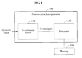
- FIG. 1 is a block diagram illustrating a pattern extraction apparatus according to an exemplary embodiment.
- a pattern extraction apparatus 100 includes an event-based sensor 110 and a processor 130.
- the processor 130 may be implemented by a microprocessor, a controller, a central processing unit (CPU), an arithmetic logic unit (ALU), a digital signal processor (DSP), a field programmable gate array (FPGA), a programmable logic unit (PLU), one or more general-purpose or special purpose computers capable of responding to and executing instructions, or various combinations thereof.
- CPU central processing unit
- ALU arithmetic logic unit
- DSP digital signal processor
- FPGA field programmable gate array
- PLU programmable logic unit
- exemplary embodiments may be extended to various apparatuses.
- exemplary embodiments may also be applicable to various computing apparatuses including pattern extraction apparatuses, mobile apparatuses, or various security apparatuses.
- the mobile apparatuses may include, for example, smartphones or wearable devices.
- the event-based sensor 110 outputs an event signal in response to a dynamic input.
- the event signal may include time information and identification information corresponding to the dynamic input.
- the dynamic input may include an event to change light incident on at least one pixel in the event-based sensor 110.
- the identification information may be an address of a plurality of pixels included in the event-based sensor 110.
- the time information may include a timestamp indicating a time at which the dynamic input is sensed by at least one pixel in the event-based sensor 110.
- the event-based sensor 110 may include a plurality of sensing pixels.
- the event-based sensor 110 may generate an event signal including identification information of an active pixel sensing an event among the plurality of sensing pixels.
- the event-based sensor 110 may use a neuromorphic sensing scheme, according to an exemplary embodiment.
- the dynamic input may include an event to change light incident on at least one pixel in the event-based sensor 110, as described above.
- the event may be, for example, an event associated with a change in an input.
- the event may include, for example, an event in which an intensity of incident light changes, an event in which a color of incident light changes, an event in which a volume of input sound changes, an event in which a frequency of input sound changes, or an event in which a strength of stimulation changes.
- the event-based sensor 110 may be an event-based vision sensor.
- the identification information may include location information indicating at least one pixel sensing the dynamic input among a plurality of pixels included in the event-based sensor 110.
- the event-based sensor 110 is assumed as an event-based vision sensor to sense an event in which an intensity of incident light changes, however, there is no limitation thereto and this is provided by way of an example only. Accordingly, exemplary embodiments may also be applied to various event-based sensors.
- the plurality of sensing pixels in the event-based sensor 110 may sense an event, for example, an event in which an intensity of incident light changes.
- a sensing pixel that senses an event among the plurality of sensing pixels may be referred to as an "active pixel.”
- an activation signal may be generated.
- the identification information may include location information indicating at least one pixel sensing the dynamic input among a plurality of pixels included in the event-based sensor 110, as described above, according to an exemplary embodiment.
- the event-based sensor 110 may generate the identification information of the active pixel.
- the event-based sensor 110 may generate an event signal including location information to identify an active pixel based on an activation signal generated by the active pixel.
- the event-based sensor 110 may asynchronously generate and output an event signal and accordingly, may operate at a high speed and low power in comparison to a frame-based vision sensor configured to scan all pixels for each frame.
- the identification information may be an address of a plurality of pixels included in the event-based sensor 110.
- the event-based sensor 110 may generate an asynchronous address event (AE) signal based on active pixels. For example, when a change in a log intensity after a last event exceeds an upper threshold or a lower threshold, the event-based sensor 110 may generate an ON event signal or an OFF event signal.
- the event-based sensor 110 may additionally generate timing information of the event signal.
- the event-based sensor 110 may interface with a synchronous system based on the timing information. Due to a low density and a low latency of an output of the event-based sensor 110, the event-based sensor 110 may be used for a high-speed object tracking application requiring feedback of a quick response.
- the high-speed object tracking application may include, for example, high-speed robotics.
- An event-based sensor may be used to acquire an image from various apparatuses including a smartphone, a tablet personal computer (PC), a television (TV) and a display.
- an event-based sensor may be used in an interface of a smartphone.
- the event-based sensor may be used in, for example, a non-contact gesture recognition interface.
- the interface may be used to recognize a gesture to unlock a smartphone, a gesture to turn up a volume of the smartphone, or a gesture to turn over pages on the smartphone.
- the event-based sensor may accurately and efficiently recognize a non-contact gesture.
- an event-based sensor may be used in a security camera. In this example, the event-based sensor may be used to recognize an object that stops moving using the security camera.
- the event-based sensor 110 may output an event signal.
- An output of an event-based vision sensor may include an event signal corresponding to a real activity as well as an event signal corresponding to a background noise activity.
- the event signal corresponding to the background noise activity may be generated by a junction leakage current or a thermal noise occurring in switches connected to floating nodes in sensing pixels of the event-based sensor 110.
- the event-based sensor 110 may generate a pass flag to identify event signals that are spatiotemporally associated with each other.
- the event-based sensor 110 may reduce a communication and computation load, and may enhance an information rate.
- a background noise activity has a random pattern, it may be easily removed through filtering using a spatial correlation by way of an example.
- the event-based sensor 110 may use a power-gating scheme.
- the power-gating scheme may be a scheme of minimizing power consumption by activating only a communication circuit and a threshold detection circuit corresponding to a sensing pixel that senses an event.
- the event-based sensor 110 may use a correlation filter chip. By using the correlation filter chip, the event-based sensor 100 may be applied to an embedded neuromorphic visual and auditory system requiring low power consumption and quick response.
- the time information may include a timestamp indicating a time at which the dynamic input is sensed by at least one pixel in the event-based sensor 110, as described above, according to an exemplary embodiment.
- the event-based sensor 110 may generate a timestamp indicating a time at which the dynamic input is sensed by an active pixel. In response to the active pixel sensing an event, an activation signal may be generated.
- the event-based sensor 110 may generate a timestamp based on a time at which an activation signal is generated.
- the processor 130 may generate a timestamp in response to the event signal being received from the event-based sensor 110.
- the processor 130 extracts a static pattern associated with the dynamic input, based on the event signal.
- the dynamic input may include an event to change light incident on at least one pixel in the event-based sensor 110.
- the static pattern may correspond to an appearance of an object associated with the dynamic input.
- the dynamic input may include a motion of an object, and the static pattern may correspond to an appearance of the object in a state in which the motion stops.
- a process by which the processor 130 extracts the static pattern will further be described.
- the processor 130 may store the identification information and the time information based on the event signal, and may extract the static pattern based on the stored identification information and the stored time information. For example, the processor 130 may extract the static pattern based on history of the identification information and the time information based.
- the identification information and the time information may be stored in a memory 140 in the form of a timestamp map.
- the pattern extraction apparatus 100 may include a memory 140 to store a timestamp map.
- a memory may be internal to the pattern extraction apparatus or may be external thereto connected via a network.
- the memory may include a buffer, a flash memory, a hard drive, and so on.
- the timestamp map will be further described with reference to FIG. 2 according to an exemplary embodiment.
- FIG. 2 is a view illustrating a timestamp map according to an exemplary embodiment.
- a timestamp map 200 includes elements corresponding to pixels in the event-based sensor 110.
- an element 201 stores a timestamp corresponding to a pixel located at (i, j) among pixels included in the event-based sensor 110.
- Each of the elements in the timestamp map 200 may store a latest time at which a timestamp signal corresponding to each of the elements is received. For example, referring to FIG. 2 , last time when a timestamp signal corresponding to the element 201 located at (i, j) is received is T i,j , and last time when a timestamp signal corresponding to an element 202 located at (i, j+1) is received is T i,j+1 .
- a time point in which a timestamp signal is received may be referred to as a "timestamp" according to an exemplary embodiment.
- the processor 130 may update the timestamp map 200 based on the received timestamp signal. For example, the processor 130 may detect an element corresponding to the received timestamp signal among a plurality of elements included in the timestamp map 200, and may update a value stored in the detected element to a timestamp at which the timestamp signal is received.
- the processor 130 may store a time in which a new timestamp signal is received in a millisecond (ms) or less or a microsecond ( ⁇ s) or less, for each of the elements, according to an exemplary embodiment.
- the processor 130 may extract the static pattern based on a timestamp of a last timestamp signal received in each of the elements, regardless of a history of timestamp signals received over time. Thus, the processor 130 may extract the static pattern with a small amount of calculation and a small memory capacity.
- the processor 130 may overwrite the received time information using a storage element corresponding to the received identification information.
- the processor 130 may discard a value stored in advance in the storage element, and may store the received time information in the storage element.
- the static pattern will further be described with reference to FIG. 3 according to an exemplary embodiment.
- FIG. 3 is a flow diagram illustrating a static pattern extraction result according to an exemplary embodiment.
- FIG. 3 illustrates an output 10 based on an event signal at a time t 1 , an output 21 based on an event signal at a time t 2 , and a static pattern 22 extracted based on a timestamp map.
- the time t 1 corresponds to a state in which an object is moving
- the time t 2 corresponds to a state in which the object is stationary.
- the object exists in sensing area at the time t 1 and t 2 .
- an output corresponding to the event signal may basically change from the output 10 to the output 21 when the object stops moving.
- the output 10 may be reconstructed in the form of the static pattern 22.
- the processor 130 extracts the static pattern associated with the dynamic input based on the identification information and the time information included in the event signal. For example, the processor 130 may extract the static pattern based on a ridge of a timestamp map. A timestamp of a last received timestamp signal may be stored in the timestamp map. When an object is moving, various timestamps may be stored in the timestamp map. When times of the timestamps are assumed as altitudes, timestamps in a predetermined time slot may form a ridge. The processor 130 may extract the ridge from the timestamp map. The ridge will be further described with reference to FIGS. 4 and 5 , according to an exemplary embodiment.
- FIGS. 4 and 5 are views illustrating a ridge of a timestamp map according to an exemplary embodiment.
- FIG. 4 illustrates a timestamp map generated based on an event signal for a moving object.
- an X axis and a Y axis each represent location information of a pixel sensing a dynamic input
- a Z axis represents a timestamp.
- the location information may correspond to coordinates of the timestamp map
- time information may correspond to an altitude of the timestamp map.
- elements of the timestamp map may become dark. Accordingly, a darkest region of the timestamp map of FIG. 4 may correspond to a ridge or peak of movement.
- FIG. 5 is a two dimensional diagram of the timestamp map such as the one shown in FIG. 4 according to an exemplary embodiment.
- an X axis and a Y axis each represent location information of a pixel sensing a dynamic input.
- the location information may correspond to coordinates of the timestamp map.
- "2.1" through “2.8" of a color map in a right side of a graph of FIG. 5 may refer to timestamp values of a pixel sensing a dynamic input.
- a region with a color corresponding to "2.8" in the timestamp map may include pixels having a timestamp value of "2.8.”
- information on a movement of the object may remain in the timestamp map.
- the information on the movement of the object may include movement history of the object.
- the darkest region corresponding to the ridge in the timestamp map indicates information about a latest movement.
- pixels having a timestamp value of "2.8" in the timestamp map may include information about the latest movement.
- the processor 130 may extract a static pattern based on the ridge of the timestamp map and accordingly, may provide information on an appearance of the object despite a stationary state of the object, according to an exemplary embodiment.
- the processor 130 extracts a ridge based on identification information and time information of a timestamp map.
- the processor 130 may determine the ridge using various schemes.
- the processor 130 may determine a ridge based on elements storing time information within a threshold time interval among a plurality of elements included in the timestamp map.
- the processor 130 may track a ridge so that a thickness of an edge included in the ridge may be equal to or less than a threshold thickness.
- FIGS. 6 through 12 a process of determining a ridge will further be described with reference to FIGS. 6 through 12 according to an exemplary embodiment.
- FIG. 6 is a view illustrating a process of extracting a static pattern based on a threshold time interval according to an exemplary embodiment.
- FIG. 6 illustrates a 20 x 20 timestamp map with timestamps.
- the timestamp map of FIG. 6 shows that an object moved during a period from a time "29" to a time "36" and that a current time is now past the time "36.”
- the processor 130 may determine a ridge based on elements storing time information within a threshold time interval among a plurality of elements included in a timestamp map. For example, the processor 130 may set the threshold time interval based on a current time. According to an exemplary embodiment, elements corresponding to timestamps within the threshold time interval based on the current time may be used to determine a ridge.
- the processor 130 may set the threshold time interval to a unit time of "5" from the current time.
- elements corresponding to timestamps, each having a value equal to or greater than "35” may be determined to form a ridge, as shown in the timestamp map of FIG. 6 according to an exemplary embodiment.
- the processor 130 may adjust a length of the threshold time interval based on a number of extracted elements. When a large number of elements or a small number of elements exist during the threshold time interval, it may be difficult to recognize an appearance of an object. Accordingly, the processor 130 may adjust the length of the threshold time interval to a level suitable for recognition of the appearance of the object. For example, the processor 130 may set a reference value of a number of elements included in a static pattern, and may adjust the length of the threshold time interval based on the reference value.
- the reference value may include at least one of a minimum value and a maximum value.
- a reference value may be set in advance or may be dynamically adjusted based on a certain condition e.g., sharpness of a static pattern.
- the processor 130 may determine a ridge based on elements storing time information within the threshold time interval with the adjusted length.
- elements corresponding to timestamps, each having a value of "35” or "36,” in the timestamp map of FIG. 6 may be determined to form a ridge.
- a process of adjusting a number of elements will be further described with reference to FIGS. 7 through 10 according to an exemplary embodiment.
- a number of elements being extracted may be too many or not enough, which would make it difficult to recognize an appearance of an object.
- whether the number of elements is too many or not enough may be determined based on a reference value.
- the reference value may be experimentally determined. For example, an object is detected from a portion where a motion occurs, an image of the object is acquired from an event occurring during the motion, and a number of pixels used to generate the image is calculated. In this example, a number of pixels required to reconstruct the image may be predicted.
- an event occurs in only a portion where a motion occurs, and accordingly in an exemplary embodiment only the portion where the motion occurs is analyzed regardless of a portion where a motion does not occur at least once.
- FIGS. 7 and 8 are flow diagrams illustrating a process of extracting a static pattern when a minimum number of elements is set according to an exemplary embodiment.
- a time diagram corresponding to an element in which an event is sensed shows a number of elements in which an event is sensed over time.
- the number of the elements in which the event is sensed may repeatedly increase and decrease, which may indicate that a moving state and a stationary state of an object are repeated.
- FIG. 7 illustrates an element included in a static pattern and a number of elements used to extract the static pattern over time.
- the number of the elements used to extract the static pattern may be controlled by adjusting a length of a threshold time interval.
- th l denotes a minimum number of elements.
- the processor 130 may adjust a length of a threshold time interval so that the number of the elements included in the static pattern may be equal to or greater than the minimum number th l . For example, in a portion 31 of FIG. 7 , the number of the elements in which the event is sensed may decrease in response to an object being stationary according to an exemplary embodiment.
- the processor 130 may properly adjust the length of the threshold time interval so that the number of the elements included in the static pattern may be equal to or greater than the minimum number th l .
- the processor 130 may properly adjust the length of the threshold time interval so that the number of the elements included in the static pattern may be equal to or greater than the minimum number th l .
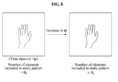
- FIG. 8 illustrates an operation of the processor 130 to sharpen the static pattern for example in the portion 31 of FIG. 7 , according to an exemplary embodiment.
- the static pattern may have low sharpness due to an insufficient number of elements used to extract the static pattern.
- the processor 130 may increase a number of elements used to extract the static pattern by increasing the length of the threshold time interval (tp), to enhance the sharpness of the static pattern.
- tp threshold time interval
- a sharpness of a static pattern representing an appearance of an object may increase in response to an increase in the length of the threshold time interval.
- FIGS. 9 and 10 are flow diagrams illustrating a process of extracting a static pattern when a maximum number of elements is set according to an exemplary embodiment.
- FIG. 9 shows a number of elements over time, a minimum number th l of elements, and a maximum number th h of elements.
- the processor 130 may adjust a length of a threshold time interval so that a number of elements included in the static pattern may be equal to or greater than the minimum number th l and may be equal to or less than the maximum number th h . For example, in a portion 32 of FIG. 9 , a number of elements in which an event is sensed increases based on a movement of an object.
- the processor 130 may properly adjust the length of the threshold time interval so that the number of the elements include in the static pattern may be equal to or less than the maximum number th h .
- the length of the threshold time interval is properly adjusted, a sharpness of the static pattern may be enhanced.
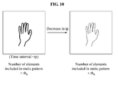
- FIG. 10 is a flow diagram illustrating an image in which the time interval is decreased such as an operation of the processor 130 in the portion 32 of FIG. 9 , according to an exemplary embodiment.
- the processor 130 may properly control the number of elements used to extract the static pattern by reducing the length of the threshold time interval, to enhance a sharpness of the static pattern.
- a sharpness of a static pattern representing an appearance of an object may increase in response to a decrease in the length of the threshold time interval, according to an exemplary embodiment.
- the processor 130 may track a ridge so that a thickness of an edge included in the ridge may be equal to or less than a threshold thickness. A process of tracking a ridge will be further described with reference to FIGS. 11 and 12 .
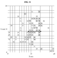
- FIGS. 11 and 12 are views illustrating a process of extracting a static pattern based on a thickness of an edge according to an exemplary embodiment.
- FIG. 11 illustrates a 20 x 20 timestamp map with timestamps.
- the timestamp map of FIG. 11 shows that an object moved during a period from a time "29" to a time "36" and that a current time is after the time "36.”
- the processor 130 may track a ridge so that a thickness of an edge included in the ridge may be equal to or less than a threshold thickness. For example, when the thickness of the edge is determined based on a number of elements in an X-axis direction, and when a threshold thickness is set to "5," elements or pixels corresponding to timestamps, each having a value between "33" and "36,” may be determined to form a ridge, as shown in the timestamp map of FIG. 11 , according to an exemplary embodiment.
- the thickness of the edge may be determined by various schemes.
- the thickness of the edge may be determined, for example, based on a number of elements in an X-axis direction, a number of elements in a Y-axis direction, a width perpendicular to a direction of the ridge, or various combinations thereof. This is provided by way of an example and not by way of a limitation.
- Tracking of a ridge may be applicable to an exemplary embodiment in which an object has a pattern. For example, when an object has a pattern, pixels used to reconstruct the pattern as well as pixels used to reconstruct a visible outline may be required. In an exemplary embodiment, a plurality of pixels may be used to represent an appearance of the object, in comparison to when an object does not have a pattern. Also, a static pattern may be properly extracted from a timestamp map through tracking of a ridge based on a thickness of an edge.
- a moving object may have a pattern, for example, a repetitive pattern.
- a pattern for example, a repetitive pattern.
- the static pattern may have a low sharpness due to an insufficient number of elements used to extract the pattern together with a visible outline of the object.
- a sharp appearance of an object may be obtained as shown in static patterns 41 and 42 at points in time "1" and "2" based on a proper number of elements used to extract the pattern together with the visible outline of the object.
- a threshold thickness may be variously defined.
- the threshold thickness may be defined as a minimum thickness, an average thickness and a maximum thickness among thicknesses of edges included in a ridge, or various combinations thereof.
- the processor 130 may track the ridge so that a thickness of each of the edges in the ridge may be equal to or less than the average thickness.
- the processor 130 may extract a sharp static pattern of an object with a complex pattern by tracking a ridge based on a thickness of an edge in the ridge according to an exemplary embodiment.
- the timestamp map may include a plurality of regions.
- the processor 130 may set a plurality of regions in a timestamp map, and may extract a static pattern from each of the regions.
- the processor 130 may set a plurality of regions corresponding to the plurality of objects in a timestamp map.
- a static pattern of each of a plurality of objects may be clearly extracted, despite a time difference between movements of the objects.
- the plurality of regions will be further described with reference to FIGS. 13 and 14 , according to an exemplary embodiment.
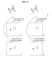
- FIGS. 13 and 14 are views illustrating a process of extracting a static pattern based on a plurality of regions set in a timestamp map according to an exemplary embodiment.
- FIG. 13 illustrates movements of an object during a period from a time t 1 to a time t 2 , first static patterns 51 and 52, and second static patterns 61 and 62.
- the first static patterns 51 and 52 may be extracted from a single region
- the second static patterns 61 and 62 may be extracted from a plurality of regions.
- a hand and a head of a user may be referred to as a first object and a second object, respectively.
- the first object and the second object move together at the time t 1
- the second object moves at the time t 2 .
- a criterion to extract a static pattern may be equally applied to the entire timestamp map.
- both an appearance of the first object and an appearance of the second object may be extracted as shown in the first static pattern 51.
- a ridge may be formed based on a movement of the second object.
- the appearance of the second object may be extracted, as shown in the second static pattern 52 without the first object.
- the processor 130 may set a criterion to extract a static pattern so that a ridge may be formed based on the appearance of the first object in a first region. Also, the processor 130 may set another criterion to extract a static pattern so that a ridge may be formed based on the appearance of the second object in a second region, as shown in element 62 of FIG. 13 .
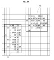
- FIG. 14 illustrates a first region 71 and a second region 72 for a plurality of objects in a timestamp map according to an exemplary embodiment.
- the first region 71 and the second region 72 may correspond to the first object and the second object, respectively.
- the first region 71 may include elements corresponding to timestamps, each having a value between "53" and "57.”
- the second region 72 may include elements corresponding to timestamps, each having a value between "60" and "63.” Accordingly, the first object and the second object may be determined to sequentially move according to an exemplary embodiment. That is, in an exemplary embodiment, regions may be determined based on the timestamps.
- each region may correspond to a particular, non-overlapping range of timestamps such as region A, all timestamps having values between 1 and 15, region B, all timestamps having values between 16 and 30.
- timestamp values maybe generated.
- regions may be set. The above is provided by way of an example, not by way of a limitation.
- regions may be determined by a pre-trained classifier.
- the processor 130 may set the first region 71 and the second region 72 based on a distribution of the timestamps. For example, the processor 130 may set the first region 71 and the second region 72 based on a part of an object corresponding to a dynamic input. The processor 130 may set individual criteria to extract a pattern for each of the first region 71 and the second region 72. For example, the processor 130 may set individual threshold time intervals for each of the first region 71 and the second region 72. Also, the processor 130 may track a ridge based on a thickness of an edge included in the ridge from each of the first region 71 and the second region 72. The processor 130 may set individual threshold thicknesses for each of the first region 71 and the second region 72.
- a representative process of extracting a static pattern based on a threshold time interval is described according to an exemplary embodiment, by way of an example and not by way of a limitation.
- the processor 130 may extract a static pattern of the first object from the first region 71 based on a first threshold time interval for the first region 71, and may extract a static pattern of the second object from the second region 72 based on a second threshold time interval for the second region 72. For example, when a current time is set to "65" in the timestamp map of FIG. 14 , the first threshold time interval and the second threshold time interval may be set as unit times of "10" and "3,” respectively.
- the above-described process of extracting a static pattern based on a single region may be applied to a process of extracting a static pattern based on a plurality of regions.
- the processor 130 may adjust a length of a threshold time interval based on a number of elements included in each of the first region 71 and the second region 72.
- the processor 130 may adjust the length of the threshold time interval based on a number of valid event signals received based on each of the first region 71 and the second region 72.
- the valid event signals may refer to event signals processed to be valid. Whether an event signal is valid may be determined based on a time at which the event signal is received.
- the processor 130 may adjust the length of the threshold time interval. In other words, the processor 130 may adjust the length of the threshold time interval only when a new event signal is received.
- the above description may be applicable to adjusting of the threshold time interval in the other situations. This is provided by way of an example only and not by way of a limitation.
- FIG. 15 is a block diagram illustrating a pattern extraction apparatus according to yet another exemplary embodiment.
- a pattern extraction apparatus 100-2 includes an event-based sensor 110, a depth sensor 120, and a processor 130.
- the pattern extraction apparatus 100-2 may generate a plurality of timestamp maps for each depth, and may extract static patterns from the plurality of timestamp maps for each depth.
- the pattern extraction apparatus 100-2 may properly reconstruct a static pattern of each of a plurality of objects by managing the plurality of timestamp maps for each depth, despite an occlusion between the objects.
- the event-based sensor 110 outputs an event signal in response to a dynamic input.
- the event signal may include identification information and time information corresponding to the dynamic input.
- the above description of the event-based sensor 110 and the processor 130 of FIG. 1 may also be applicable, by way of an example, to the event-based sensor 110 and the processor 130 of FIG. 15 and accordingly, further description of the event-based sensor 110 and the processor 130 of FIG. 15 will not be repeated here.
- the depth sensor 120 outputs depth information.
- the depth sensor 120 includes a plurality of sensing pixels.
- the depth sensor 120 may output depth information sensed by the plurality of sensing pixels.
- the depth sensor 120 may have the same resolution as that of the event-based sensor 110.
- the depth sensor 120 may output depth information corresponding to the dynamic input.
- the depth sensor 120 may receive an event signal, and may output depth information sensed by a pixel corresponding to location information of the received event signal.
- the processor 130 may generate a plurality of timestamp maps for each of different depths.
- the processor 130 may update one of the timestamp maps based on the event signal received from the event-based sensor 110 and the depth information received from the depth sensor 120. For example, when first depth information is received in response to a first event signal, the processor 130 may update a timestamp based on the first event signal in a first timestamp map corresponding to a first depth region.
- An operation of the processor 130 in association with a plurality of timestamp maps will be described with reference to FIGS. 16 and 17 , according to an exemplary embodiment.
- FIG. 16 is a flow diagram illustrating a process of processing a plurality of timestamp maps according to an exemplary embodiment.
- FIG. 16 illustrates the processor 130, a first timestamp map 210, a second timestamp map 220 and a third timestamp map 230.
- the first timestamp map 210, the second timestamp map 220 and the third timestamp map 230 may correspond to a first depth region, a second depth region and a third depth region, respectively.
- the first timestamp map 210 through the third timestamp map 230 may be referred to as two-dimensional (2D) timestamp maps.
- the processor 130 may select a timestamp map corresponding to the event signal from the first timestamp map 210 through the third timestamp map 230 based on depth information. For example, when the depth information corresponds to the first depth region, the processor 130 may select the first timestamp map 210. The processor 130 may update the first timestamp map 210 based on identification information and time information included in the event signal.
- the processor 130 may extract a ridge from at least one of the first timestamp map 210 through the third timestamp map 230.
- An exemplary process of extracting a ridge has been described above and accordingly, further description of the process will not be repeated here.
- the processor 130 may extract a static pattern based on the extracted ridge.
- the processor 130 may extract a plurality of static patterns from each of the first timestamp map 210 through the third timestamp map 230.
- the processor 130 may generate a single composite map based on the first timestamp map 210 through the third timestamp map 230, and may extract a static pattern based on a ridge of the composite map.
- the processor 130 may generate a single composite map based on a latest timestamp among the overlapping timestamps. For example, a composite map may be generated based on a latest timestamp from all three timestamp maps. In other words, in an exemplary embodiment, from various timestamp maps (one for each depth), the highest value for each pixel is obtained and one composite map is generated.
- Exemplary embodiments may be modified to a scheme of generating a three-dimensional (3D) timestamp map, although not shown in the drawings, instead of a plurality of 2D timestamp maps.
- a 3D timestamp map may store a pair of time information and depth information in an element corresponding to identification information.
- the processor 130 may store time information and depth information in a storage element corresponding to identification information.
- the depth information may be quantized to predetermined depth regions.
- the processor 130 may generate a 3D timestamp map including a pair of latest time information and latest depth information for each of the depth regions.
- the processor 130 may overlap a pair of new time information and the new depth information on a corresponding element.
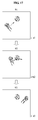
- FIG. 17 is a flow diagram illustrating a result obtained by processing a plurality of timestamp maps according to an exemplary embodiment.
- FIG. 17 illustrates static patterns 91, 92 and 93 extracted from a plurality of timestamp maps.
- Each of the static patterns 91, 92 and 93 includes a first object corresponding to a user's hand and a second object corresponding to a user's face.
- the first object and the second object are assumed to have different depths, and an arrow in each of the static patterns 91 and 92 indicate a movement direction of the first object.
- the processor 130 may update an event signal corresponding to the first object in a first timestamp map, and may update an event signal corresponding to the second object in a second timestamp map. Accordingly, when an occlusion between the first object and the second object occurs, a static pattern of the first object and a static pattern of the second object may be independently reconstructed. For example, referring to FIG. 17 , an occlusion between the first object and the second object may occur between times t2 and t3. In this example, both the first object and the second object may be independently reconstructed based on the plurality of timestamp maps as shown in the static pattern 93.
- the processor 130 may set a plurality of regions in at least one of the plurality of timestamp maps.
- the processor 130 may set the plurality of regions based on a distribution of timestamps.
- the processor 130 may set individual criteria to extract a pattern for each of the regions. For example, the processor 130 may set individual threshold time intervals for each of the regions, and may adjust a length of each of the threshold time intervals based on a number of elements included in each of the regions.
- the above description may be applicable to a pattern extraction process for the plurality of regions, according to an exemplary embodiment.
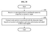
- FIG. 18 is a flowchart illustrating a pattern extraction method according to an exemplary embodiment.
- a pattern extraction apparatus receives an event signal in response to a dynamic input.
- the event signal may be output by an event-based sensor.
- the pattern extraction apparatus extracts a static pattern associated with the dynamic input based on identification information and time information included in the event signal.
- FIGS. 1 through 17 The above-description of FIGS. 1 through 17 is also applicable to the pattern extraction method of FIG. 18 , by way of an example, and accordingly, further description thereof will not be repeated here.
- both the thickness of the edges and the number of elements may be used to determine a static pattern associated with the event signal.
- the number of elements may be adjusted so that an edge may have a preset thickness. For example, when an object is moving, an event signal may be generated in an edge of the object, and the number of elements may be adjusted so that edges corresponding to the event signal may continue to have a thickness of average about 2 pixels. This is provided by way of an example and not by way of a limitation.
- a combination of the thickness of the edges and the number of elements may be used to generate the pattern.
- the elements or components described herein may be implemented using hardware components, software components, or a combination thereof.
- the hardware components may include microphones, amplifiers, band-pass filters, audio to digital convertors, and processing devices.
- a processing device may be implemented using one or more general-purpose or special purpose computers, such as, for example, a processor, a controller and an ALU, a DSP, a microcomputer, an FPGA, a PLU, a microprocessor or any other device capable of responding to and executing instructions in a defined manner.
- the processing device may run an operating system (OS) and one or more software applications that run on the OS.
- the processing device also may access, store, manipulate, process, and create data in response to execution of the software.
- OS operating system
- a processing device may include multiple processing elements and multiple types of processing elements.
- a processing device may include multiple processors or a processor and a controller.
- different processing configurations are possible, such a parallel processors.
- the software may include a computer program, a piece of code, an instruction, or some combination thereof, to independently or collectively instruct or configure the processing device to operate as desired.
- Software and data may be embodied permanently or temporarily in any type of machine, component, physical or virtual equipment, computer storage medium or device, or in a propagated signal wave capable of providing instructions or data to or being interpreted by the processing device.
- the software also may be distributed over network coupled computer systems so that the software is stored and executed in a distributed fashion.
- the software and data may be stored by one or more non-transitory computer readable recording mediums.
- the above-described exemplary embodiments may be recorded in non-transitory computer-readable media including program instructions to implement various operations which may be performed by a computer.
- the media may also include, alone or in combination with the program instructions, data files, data structures, and the like.
- the program instructions recorded on the media may be those specially designed and constructed for the purposes of the exemplary embodiments, or they may be of the well-known kind and available to those having skill in the computer software arts.
- non-transitory computer-readable media examples include magnetic media such as hard disks, floppy disks, and magnetic tape; optical media such as CD ROM discs and DVDs; magneto-optical media such as optical discs; and hardware devices that are specially configured to store and perform program instructions, such as read-only memory (ROM), random access memory (RAM), flash memory, and the like.
- program instructions include both machine code, such as code produced by a compiler, and files containing higher level code that may be executed by the computer using an interpreter.
- the described hardware devices may be configured to act as one or more software modules in order to perform the operations of the above-described exemplary embodiments, or vice versa.
Landscapes
- Engineering & Computer Science (AREA)
- Theoretical Computer Science (AREA)
- Physics & Mathematics (AREA)
- General Physics & Mathematics (AREA)
- General Engineering & Computer Science (AREA)
- Human Computer Interaction (AREA)
- Multimedia (AREA)
- Computer Vision & Pattern Recognition (AREA)
- General Health & Medical Sciences (AREA)
- Health & Medical Sciences (AREA)
- Computer Hardware Design (AREA)
- Psychiatry (AREA)
- Social Psychology (AREA)
- Audiology, Speech & Language Pathology (AREA)
- Image Analysis (AREA)
- Probability & Statistics with Applications (AREA)
Applications Claiming Priority (1)
| Application Number | Priority Date | Filing Date | Title |
|---|---|---|---|
| KR1020150059746A KR102307055B1 (ko) | 2015-04-28 | 2015-04-28 | 이벤트 기반 센서의 출력에 기초하여 정적 패턴을 추출하는 방법 및 장치 |
Publications (2)
| Publication Number | Publication Date |
|---|---|
| EP3089111A1 true EP3089111A1 (de) | 2016-11-02 |
| EP3089111B1 EP3089111B1 (de) | 2019-01-09 |
Family
ID=55910759
Family Applications (1)
| Application Number | Title | Priority Date | Filing Date |
|---|---|---|---|
| EP16167010.4A Active EP3089111B1 (de) | 2015-04-28 | 2016-04-26 | Verfahren und vorrichtung zur extraktion statischer muster auf grundlage der ausgabe eines ereignisbasierten sensors |
Country Status (4)
| Country | Link |
|---|---|
| US (2) | US9921643B2 (de) |
| EP (1) | EP3089111B1 (de) |
| KR (1) | KR102307055B1 (de) |
| CN (1) | CN106095262B (de) |
Cited By (1)
| Publication number | Priority date | Publication date | Assignee | Title |
|---|---|---|---|---|
| WO2019137973A1 (en) * | 2018-01-11 | 2019-07-18 | Gensight Biologics | Method and device for processing asynchronous signals generated by an event-based light sensor |
Families Citing this family (23)
| Publication number | Priority date | Publication date | Assignee | Title |
|---|---|---|---|---|
| CN111611575A (zh) * | 2016-10-13 | 2020-09-01 | 创新先进技术有限公司 | 基于虚拟现实场景的业务实现方法及装置 |
| KR102282140B1 (ko) * | 2017-03-08 | 2021-07-28 | 삼성전자주식회사 | 픽셀, 픽셀 구동 회로 및 이를 포함하는 비전 센서 |
| CN108574793B (zh) | 2017-03-08 | 2022-05-10 | 三星电子株式会社 | 被配置为重新生成时间戳的图像处理设备及包括其在内的电子设备 |
| US10237481B2 (en) * | 2017-04-18 | 2019-03-19 | Facebook Technologies, Llc | Event camera for generation of event-based images |
| EP3393122A1 (de) * | 2017-04-18 | 2018-10-24 | Oculus VR, LLC | Ereigniskamera |
| CN111149350B (zh) * | 2017-09-28 | 2022-02-22 | 苹果公司 | 使用事件相机生成静态图像 |
| US11379996B2 (en) | 2017-11-14 | 2022-07-05 | Apple Inc. | Deformable object tracking |
| EP3721323B1 (de) * | 2017-12-04 | 2025-04-16 | National University of Singapore | Sensorbasierte kommunikationsvorrichtung und -verfahren |
| US11064173B2 (en) | 2017-12-14 | 2021-07-13 | International Business Machines Corporation | Photographic directional light reference for articulating devices |
| WO2019175734A1 (en) * | 2018-03-14 | 2019-09-19 | Insightness Ag | Event-based vision sensor with direct memory control |
| US10887535B2 (en) * | 2018-07-18 | 2021-01-05 | The Regents Of The University Of California | Query driven image sensing |
| US11902677B2 (en) | 2018-11-12 | 2024-02-13 | Magic Leap, Inc. | Patch tracking image sensor |
| US11809613B2 (en) * | 2018-11-12 | 2023-11-07 | Magic Leap, Inc. | Event-based camera with high-resolution frame output |
| WO2020101891A1 (en) | 2018-11-12 | 2020-05-22 | Magic Leap, Inc. | Depth based dynamic vision sensor |
| CN113316755B (zh) | 2019-01-25 | 2024-04-23 | 索尼高级视觉传感股份公司 | 使用基于事件的视觉传感器的环境模型保持 |
| EP3922011A4 (de) | 2019-02-07 | 2022-10-26 | Magic Leap, Inc. | Leichte realitätsübergreifende vorrichtung mit geringer leistungsaufnahme und mit hoher zeitlicher auflösung |
| JP7720783B2 (ja) | 2019-02-07 | 2025-08-08 | マジック リープ, インコーポレイテッド | 受動深度抽出を伴う軽量のクロスリアリティデバイス |
| WO2020197961A1 (en) | 2019-03-27 | 2020-10-01 | Ocelot Laboratories Llc | Processing of signals using a recurrent state estimator |
| EP3730256A1 (de) * | 2019-04-26 | 2020-10-28 | Prophesee | Servosteuerungsverfahren und system zur steuerung der bewegung eines roboters |
| TWI762956B (zh) * | 2020-06-17 | 2022-05-01 | 瑞昱半導體股份有限公司 | 影像中靜止圖像的處理方法 |
| WO2022096086A1 (en) * | 2020-11-04 | 2022-05-12 | Huawei Technologies Co., Ltd. | Device and method for compensating event latency |
| CN114519017B (zh) * | 2020-11-18 | 2024-03-29 | 舜宇光学(浙江)研究院有限公司 | 用于事件相机的数据传输方法及其系统和电子设备 |
| KR20220076944A (ko) | 2020-12-01 | 2022-06-08 | 삼성전자주식회사 | 비전 센서, 이를 포함하는 이미지 처리 장치 및 비전 센서의 동작 방법 |
Citations (2)
| Publication number | Priority date | Publication date | Assignee | Title |
|---|---|---|---|---|
| EP2677500A2 (de) * | 2012-06-19 | 2013-12-25 | Samsung Electronics Co., Ltd | Ereignisbasierte Bildverarbeitungsvorrichtung und Verfahren |
| US20140363049A1 (en) * | 2011-12-21 | 2014-12-11 | Universite Pierre Et Marie Curie (Paris 6) | Method of estimating optical flow on the basis of an asynchronous light sensor |
Family Cites Families (21)
| Publication number | Priority date | Publication date | Assignee | Title |
|---|---|---|---|---|
| JP3424204B2 (ja) * | 1999-07-23 | 2003-07-07 | インターナショナル・ビジネス・マシーンズ・コーポレーション | オブジェクトの軌跡を利用したビデオ・コンテンツへのアクセス方法及び装置 |
| US20050146605A1 (en) * | 2000-10-24 | 2005-07-07 | Lipton Alan J. | Video surveillance system employing video primitives |
| US8243986B2 (en) | 2004-06-09 | 2012-08-14 | Cognex Technology And Investment Corporation | Method and apparatus for automatic visual event detection |
| JP2006067452A (ja) | 2004-08-30 | 2006-03-09 | Nikon Corp | 映像記録装置、および電子カメラ |
| WO2006078861A2 (en) * | 2005-01-18 | 2006-07-27 | Board Of Regents, The University Of Texas System | Method, system and apparatus for a time stamped visual motion sensor |
| KR101331982B1 (ko) | 2005-06-03 | 2013-11-25 | 우니페르지타에트 취리히 | 시간 의존적 이미지 데이터를 검출하기 위한 광 어레이 |
| JP2009141702A (ja) | 2007-12-06 | 2009-06-25 | Canon Inc | 撮像装置及び撮像装置の制御方法 |
| US9386281B2 (en) * | 2009-10-02 | 2016-07-05 | Alarm.Com Incorporated | Image surveillance and reporting technology |
| US8698092B2 (en) | 2010-09-10 | 2014-04-15 | Samsung Electronics Co., Ltd. | Method and apparatus for motion recognition |
| US9154747B2 (en) * | 2010-12-22 | 2015-10-06 | Pelco, Inc. | Stopped object detection |
| FR2983323B1 (fr) | 2011-11-28 | 2014-06-06 | Schneider Electric Ind Sas | Systeme de gestion de buffers d'evenements horodates |
| KR101299180B1 (ko) * | 2011-12-01 | 2013-08-22 | 주식회사 감성 | 휴대 단말의 패턴 입력 장치 및 그 방법 |
| US9075545B2 (en) | 2012-08-01 | 2015-07-07 | Hewlett-Packard Development Company, L.P. | Synchronizing sensor data using timestamps and signal interpolation |
| US9323985B2 (en) * | 2012-08-16 | 2016-04-26 | Microchip Technology Incorporated | Automatic gesture recognition for a sensor system |
| KR20140138424A (ko) * | 2013-05-23 | 2014-12-04 | 삼성전자주식회사 | 제스쳐를 이용한 사용자 인터페이스 방법 및 장치 |
| US9696812B2 (en) | 2013-05-29 | 2017-07-04 | Samsung Electronics Co., Ltd. | Apparatus and method for processing user input using motion of object |
| KR102081087B1 (ko) | 2013-06-17 | 2020-02-25 | 삼성전자주식회사 | 동기적 영상과 비동기적 영상을 위한 영상 정합 장치 및 이미지 센서 |
| US9767571B2 (en) | 2013-07-29 | 2017-09-19 | Samsung Electronics Co., Ltd. | Apparatus and method for analyzing image including event information |
| KR102203810B1 (ko) | 2013-10-01 | 2021-01-15 | 삼성전자주식회사 | 사용자 입력에 대응되는 이벤트를 이용한 유저 인터페이싱 장치 및 방법 |
| US9275284B2 (en) * | 2014-04-30 | 2016-03-01 | Sony Corporation | Method and apparatus for extraction of static scene photo from sequence of images |
| CN104182049B (zh) * | 2014-08-28 | 2017-02-15 | 华南理工大学广州学院 | 非接触式红外线二维手势动作检测与识别装置及方法 |
-
2015
- 2015-04-28 KR KR1020150059746A patent/KR102307055B1/ko active Active
-
2016
- 2016-02-08 US US15/017,711 patent/US9921643B2/en active Active
- 2016-04-25 CN CN201610260737.6A patent/CN106095262B/zh active Active
- 2016-04-26 EP EP16167010.4A patent/EP3089111B1/de active Active
-
2019
- 2019-03-04 US US16/291,685 patent/USRE48780E1/en active Active
Patent Citations (2)
| Publication number | Priority date | Publication date | Assignee | Title |
|---|---|---|---|---|
| US20140363049A1 (en) * | 2011-12-21 | 2014-12-11 | Universite Pierre Et Marie Curie (Paris 6) | Method of estimating optical flow on the basis of an asynchronous light sensor |
| EP2677500A2 (de) * | 2012-06-19 | 2013-12-25 | Samsung Electronics Co., Ltd | Ereignisbasierte Bildverarbeitungsvorrichtung und Verfahren |
Non-Patent Citations (3)
| Title |
|---|
| BO ZHAO: "Excerpts from: A BIOLOGICALLY INSPIRED HUMAN POSTURE RECOGNITION SYSTEM", THESIS, 1 January 2014 (2014-01-01), XP055298169, Retrieved from the Internet <URL:http://www.ntu.edu.sg/home/eechenss/Papers/Thesis-2014-A%20biologically%20inspired%20human%20posture%20recognition%20system.pdf> [retrieved on 20160829] * |
| FRANCO JESUS ARMANDO GARCIA ET AL: "Event-based image processing using a neuromorphic vision sensor", 2013 IEEE INTERNATIONAL AUTUMN MEETING ON POWER ELECTRONICS AND COMPUTING (ROPEC), IEEE, 13 November 2013 (2013-11-13), pages 1 - 6, XP032541092, DOI: 10.1109/ROPEC.2013.6702715 * |
| VARAD GUNJAL: "DEVELOPMENT OF FEATURE DESCRIPTORS FOR EVENT-BASED VISION SENSORS", 18 December 2012 (2012-12-18), XP055195885, Retrieved from the Internet <URL:https://www.ini.uzh.ch/~tobi/wiki/lib/exe/fetch.php?media=gunjalbachelorsthesis2012.pdf> [retrieved on 20150615] * |
Cited By (2)
| Publication number | Priority date | Publication date | Assignee | Title |
|---|---|---|---|---|
| WO2019137973A1 (en) * | 2018-01-11 | 2019-07-18 | Gensight Biologics | Method and device for processing asynchronous signals generated by an event-based light sensor |
| US11875545B2 (en) | 2018-01-11 | 2024-01-16 | Gensight Biologics | Method and device for processing asynchronous signals generated by an event-based light sensor |
Also Published As
| Publication number | Publication date |
|---|---|
| US20160320834A1 (en) | 2016-11-03 |
| US9921643B2 (en) | 2018-03-20 |
| EP3089111B1 (de) | 2019-01-09 |
| KR102307055B1 (ko) | 2021-10-01 |
| CN106095262B (zh) | 2021-04-23 |
| KR20160128030A (ko) | 2016-11-07 |
| CN106095262A (zh) | 2016-11-09 |
| USRE48780E1 (en) | 2021-10-19 |
Similar Documents
| Publication | Publication Date | Title |
|---|---|---|
| USRE48780E1 (en) | Method and apparatus for extracting static pattern based on output of event-based sensor | |
| US10410077B2 (en) | Method and apparatus for detecting error in gesture recognition | |
| KR102720734B1 (ko) | 이벤트 신호 처리 방법 및 장치 | |
| US9495758B2 (en) | Device and method for recognizing gesture based on direction of gesture | |
| KR102248404B1 (ko) | 움직임 분석 방법 및 움직임 분석 장치 | |
| US9817507B2 (en) | Method and apparatus for detecting movement of object based on event | |
| EP3131311B1 (de) | Überwachung | |
| US9898080B2 (en) | Method and apparatus for eye tracking | |
| RU2559720C2 (ru) | Устройство и способ пользовательского ввода для управления отображаемой информацией | |
| KR102433931B1 (ko) | 움직임 인식 방법 및 움직임 인식 장치 | |
| JP7823680B2 (ja) | 情報処理装置、制御方法、及びプログラム | |
| KR20160086605A (ko) | 객체 인식 방법 및 장치 | |
| JP2012191354A (ja) | 情報処理装置、情報処理方法及びプログラム | |
| CN113573061A (zh) | 一种视频抽帧方法、装置及设备 | |
| US12113954B2 (en) | Processing of signals using a recurrent state estimator | |
| WO2015060896A1 (en) | Finite state machine cursor and dynamic gesture detector recognition | |
| EP3971781A1 (de) | Verfahren und vorrichtung mit operation von neuronalem netz | |
| US20150146920A1 (en) | Gesture recognition method and apparatus utilizing asynchronous multithreaded processing | |
| Kachhava et al. | Security system and surveillance using real time object tracking and multiple cameras | |
| KR102269088B1 (ko) | 동공 추적 장치 및 방법 | |
| KR102812471B1 (ko) | 무안경 3차원 입체 영상 디스플레이 장치 및 그 방법 | |
| KR20250079779A (ko) | 이벤트 기반 비전 센서를 이용한 관심 영역 검출 방법, 및 이를 이용한 장치 | |
| KR20220083628A (ko) | 깊이 이미지 생성 장치 및 그 동작 방법 | |
| Ni et al. | Heuristic search with a new operator based Krisch combination of Image edge detection |
Legal Events
| Date | Code | Title | Description |
|---|---|---|---|
| PUAI | Public reference made under article 153(3) epc to a published international application that has entered the european phase |
Free format text: ORIGINAL CODE: 0009012 |
|
| AK | Designated contracting states |
Kind code of ref document: A1 Designated state(s): AL AT BE BG CH CY CZ DE DK EE ES FI FR GB GR HR HU IE IS IT LI LT LU LV MC MK MT NL NO PL PT RO RS SE SI SK SM TR |
|
| AX | Request for extension of the european patent |
Extension state: BA ME |
|
| 17P | Request for examination filed |
Effective date: 20170502 |
|
| RBV | Designated contracting states (corrected) |
Designated state(s): AL AT BE BG CH CY CZ DE DK EE ES FI FR GB GR HR HU IE IS IT LI LT LU LV MC MK MT NL NO PL PT RO RS SE SI SK SM TR |
|
| STAA | Information on the status of an ep patent application or granted ep patent |
Free format text: STATUS: REQUEST FOR EXAMINATION WAS MADE |
|
| STAA | Information on the status of an ep patent application or granted ep patent |
Free format text: STATUS: EXAMINATION IS IN PROGRESS |
|
| 17Q | First examination report despatched |
Effective date: 20171107 |
|
| GRAP | Despatch of communication of intention to grant a patent |
Free format text: ORIGINAL CODE: EPIDOSNIGR1 |
|
| STAA | Information on the status of an ep patent application or granted ep patent |
Free format text: STATUS: GRANT OF PATENT IS INTENDED |
|
| INTG | Intention to grant announced |
Effective date: 20180703 |
|
| GRAS | Grant fee paid |
Free format text: ORIGINAL CODE: EPIDOSNIGR3 |
|
| GRAJ | Information related to disapproval of communication of intention to grant by the applicant or resumption of examination proceedings by the epo deleted |
Free format text: ORIGINAL CODE: EPIDOSDIGR1 |
|
| GRAL | Information related to payment of fee for publishing/printing deleted |
Free format text: ORIGINAL CODE: EPIDOSDIGR3 |
|
| STAA | Information on the status of an ep patent application or granted ep patent |
Free format text: STATUS: EXAMINATION IS IN PROGRESS |
|
| GRAR | Information related to intention to grant a patent recorded |
Free format text: ORIGINAL CODE: EPIDOSNIGR71 |
|
| STAA | Information on the status of an ep patent application or granted ep patent |
Free format text: STATUS: GRANT OF PATENT IS INTENDED |
|
| GRAA | (expected) grant |
Free format text: ORIGINAL CODE: 0009210 |
|
| STAA | Information on the status of an ep patent application or granted ep patent |
Free format text: STATUS: THE PATENT HAS BEEN GRANTED |
|
| INTC | Intention to grant announced (deleted) | ||
| AK | Designated contracting states |
Kind code of ref document: B1 Designated state(s): AL AT BE BG CH CY CZ DE DK EE ES FI FR GB GR HR HU IE IS IT LI LT LU LV MC MK MT NL NO PL PT RO RS SE SI SK SM TR |
|
| INTG | Intention to grant announced |
Effective date: 20181204 |
|
| REG | Reference to a national code |
Ref country code: GB Ref legal event code: FG4D |
|
| REG | Reference to a national code |
Ref country code: CH Ref legal event code: EP Ref country code: AT Ref legal event code: REF Ref document number: 1088234 Country of ref document: AT Kind code of ref document: T Effective date: 20190115 |
|
| REG | Reference to a national code |
Ref country code: DE Ref legal event code: R096 Ref document number: 602016009110 Country of ref document: DE |
|
| REG | Reference to a national code |
Ref country code: IE Ref legal event code: FG4D |
|
| REG | Reference to a national code |
Ref country code: NL Ref legal event code: MP Effective date: 20190109 |
|
| REG | Reference to a national code |
Ref country code: LT Ref legal event code: MG4D |
|
| PG25 | Lapsed in a contracting state [announced via postgrant information from national office to epo] |
Ref country code: NL Free format text: LAPSE BECAUSE OF FAILURE TO SUBMIT A TRANSLATION OF THE DESCRIPTION OR TO PAY THE FEE WITHIN THE PRESCRIBED TIME-LIMIT Effective date: 20190109 |
|
| REG | Reference to a national code |
Ref country code: AT Ref legal event code: MK05 Ref document number: 1088234 Country of ref document: AT Kind code of ref document: T Effective date: 20190109 |
|
| PG25 | Lapsed in a contracting state [announced via postgrant information from national office to epo] |
Ref country code: ES Free format text: LAPSE BECAUSE OF FAILURE TO SUBMIT A TRANSLATION OF THE DESCRIPTION OR TO PAY THE FEE WITHIN THE PRESCRIBED TIME-LIMIT Effective date: 20190109 Ref country code: SE Free format text: LAPSE BECAUSE OF FAILURE TO SUBMIT A TRANSLATION OF THE DESCRIPTION OR TO PAY THE FEE WITHIN THE PRESCRIBED TIME-LIMIT Effective date: 20190109 Ref country code: PT Free format text: LAPSE BECAUSE OF FAILURE TO SUBMIT A TRANSLATION OF THE DESCRIPTION OR TO PAY THE FEE WITHIN THE PRESCRIBED TIME-LIMIT Effective date: 20190509 Ref country code: NO Free format text: LAPSE BECAUSE OF FAILURE TO SUBMIT A TRANSLATION OF THE DESCRIPTION OR TO PAY THE FEE WITHIN THE PRESCRIBED TIME-LIMIT Effective date: 20190409 Ref country code: PL Free format text: LAPSE BECAUSE OF FAILURE TO SUBMIT A TRANSLATION OF THE DESCRIPTION OR TO PAY THE FEE WITHIN THE PRESCRIBED TIME-LIMIT Effective date: 20190109 Ref country code: FI Free format text: LAPSE BECAUSE OF FAILURE TO SUBMIT A TRANSLATION OF THE DESCRIPTION OR TO PAY THE FEE WITHIN THE PRESCRIBED TIME-LIMIT Effective date: 20190109 Ref country code: LT Free format text: LAPSE BECAUSE OF FAILURE TO SUBMIT A TRANSLATION OF THE DESCRIPTION OR TO PAY THE FEE WITHIN THE PRESCRIBED TIME-LIMIT Effective date: 20190109 |
|
| PG25 | Lapsed in a contracting state [announced via postgrant information from national office to epo] |
Ref country code: RS Free format text: LAPSE BECAUSE OF FAILURE TO SUBMIT A TRANSLATION OF THE DESCRIPTION OR TO PAY THE FEE WITHIN THE PRESCRIBED TIME-LIMIT Effective date: 20190109 Ref country code: BG Free format text: LAPSE BECAUSE OF FAILURE TO SUBMIT A TRANSLATION OF THE DESCRIPTION OR TO PAY THE FEE WITHIN THE PRESCRIBED TIME-LIMIT Effective date: 20190409 Ref country code: GR Free format text: LAPSE BECAUSE OF FAILURE TO SUBMIT A TRANSLATION OF THE DESCRIPTION OR TO PAY THE FEE WITHIN THE PRESCRIBED TIME-LIMIT Effective date: 20190410 Ref country code: HR Free format text: LAPSE BECAUSE OF FAILURE TO SUBMIT A TRANSLATION OF THE DESCRIPTION OR TO PAY THE FEE WITHIN THE PRESCRIBED TIME-LIMIT Effective date: 20190109 Ref country code: LV Free format text: LAPSE BECAUSE OF FAILURE TO SUBMIT A TRANSLATION OF THE DESCRIPTION OR TO PAY THE FEE WITHIN THE PRESCRIBED TIME-LIMIT Effective date: 20190109 Ref country code: IS Free format text: LAPSE BECAUSE OF FAILURE TO SUBMIT A TRANSLATION OF THE DESCRIPTION OR TO PAY THE FEE WITHIN THE PRESCRIBED TIME-LIMIT Effective date: 20190509 |
|
| REG | Reference to a national code |
Ref country code: DE Ref legal event code: R097 Ref document number: 602016009110 Country of ref document: DE |
|
| PG25 | Lapsed in a contracting state [announced via postgrant information from national office to epo] |
Ref country code: SK Free format text: LAPSE BECAUSE OF FAILURE TO SUBMIT A TRANSLATION OF THE DESCRIPTION OR TO PAY THE FEE WITHIN THE PRESCRIBED TIME-LIMIT Effective date: 20190109 Ref country code: RO Free format text: LAPSE BECAUSE OF FAILURE TO SUBMIT A TRANSLATION OF THE DESCRIPTION OR TO PAY THE FEE WITHIN THE PRESCRIBED TIME-LIMIT Effective date: 20190109 Ref country code: EE Free format text: LAPSE BECAUSE OF FAILURE TO SUBMIT A TRANSLATION OF THE DESCRIPTION OR TO PAY THE FEE WITHIN THE PRESCRIBED TIME-LIMIT Effective date: 20190109 Ref country code: IT Free format text: LAPSE BECAUSE OF FAILURE TO SUBMIT A TRANSLATION OF THE DESCRIPTION OR TO PAY THE FEE WITHIN THE PRESCRIBED TIME-LIMIT Effective date: 20190109 Ref country code: DK Free format text: LAPSE BECAUSE OF FAILURE TO SUBMIT A TRANSLATION OF THE DESCRIPTION OR TO PAY THE FEE WITHIN THE PRESCRIBED TIME-LIMIT Effective date: 20190109 Ref country code: AT Free format text: LAPSE BECAUSE OF FAILURE TO SUBMIT A TRANSLATION OF THE DESCRIPTION OR TO PAY THE FEE WITHIN THE PRESCRIBED TIME-LIMIT Effective date: 20190109 Ref country code: AL Free format text: LAPSE BECAUSE OF FAILURE TO SUBMIT A TRANSLATION OF THE DESCRIPTION OR TO PAY THE FEE WITHIN THE PRESCRIBED TIME-LIMIT Effective date: 20190109 Ref country code: CZ Free format text: LAPSE BECAUSE OF FAILURE TO SUBMIT A TRANSLATION OF THE DESCRIPTION OR TO PAY THE FEE WITHIN THE PRESCRIBED TIME-LIMIT Effective date: 20190109 |
|
| PLBE | No opposition filed within time limit |
Free format text: ORIGINAL CODE: 0009261 |
|
| STAA | Information on the status of an ep patent application or granted ep patent |
Free format text: STATUS: NO OPPOSITION FILED WITHIN TIME LIMIT |
|
| PG25 | Lapsed in a contracting state [announced via postgrant information from national office to epo] |
Ref country code: SM Free format text: LAPSE BECAUSE OF FAILURE TO SUBMIT A TRANSLATION OF THE DESCRIPTION OR TO PAY THE FEE WITHIN THE PRESCRIBED TIME-LIMIT Effective date: 20190109 |
|
| REG | Reference to a national code |
Ref country code: CH Ref legal event code: PL |
|
| 26N | No opposition filed |
Effective date: 20191010 |
|
| REG | Reference to a national code |
Ref country code: BE Ref legal event code: MM Effective date: 20190430 |
|
| PG25 | Lapsed in a contracting state [announced via postgrant information from national office to epo] |
Ref country code: MC Free format text: LAPSE BECAUSE OF FAILURE TO SUBMIT A TRANSLATION OF THE DESCRIPTION OR TO PAY THE FEE WITHIN THE PRESCRIBED TIME-LIMIT Effective date: 20190109 Ref country code: LU Free format text: LAPSE BECAUSE OF NON-PAYMENT OF DUE FEES Effective date: 20190426 |
|
| PG25 | Lapsed in a contracting state [announced via postgrant information from national office to epo] |
Ref country code: CH Free format text: LAPSE BECAUSE OF NON-PAYMENT OF DUE FEES Effective date: 20190430 Ref country code: LI Free format text: LAPSE BECAUSE OF NON-PAYMENT OF DUE FEES Effective date: 20190430 |
|
| PG25 | Lapsed in a contracting state [announced via postgrant information from national office to epo] |
Ref country code: BE Free format text: LAPSE BECAUSE OF NON-PAYMENT OF DUE FEES Effective date: 20190430 Ref country code: SI Free format text: LAPSE BECAUSE OF FAILURE TO SUBMIT A TRANSLATION OF THE DESCRIPTION OR TO PAY THE FEE WITHIN THE PRESCRIBED TIME-LIMIT Effective date: 20190109 |
|
| PG25 | Lapsed in a contracting state [announced via postgrant information from national office to epo] |
Ref country code: TR Free format text: LAPSE BECAUSE OF FAILURE TO SUBMIT A TRANSLATION OF THE DESCRIPTION OR TO PAY THE FEE WITHIN THE PRESCRIBED TIME-LIMIT Effective date: 20190109 |
|
| PG25 | Lapsed in a contracting state [announced via postgrant information from national office to epo] |
Ref country code: IE Free format text: LAPSE BECAUSE OF NON-PAYMENT OF DUE FEES Effective date: 20190426 |
|
| GBPC | Gb: european patent ceased through non-payment of renewal fee |
Effective date: 20200426 |
|
| PG25 | Lapsed in a contracting state [announced via postgrant information from national office to epo] |
Ref country code: GB Free format text: LAPSE BECAUSE OF NON-PAYMENT OF DUE FEES Effective date: 20200426 |
|
| PG25 | Lapsed in a contracting state [announced via postgrant information from national office to epo] |
Ref country code: CY Free format text: LAPSE BECAUSE OF FAILURE TO SUBMIT A TRANSLATION OF THE DESCRIPTION OR TO PAY THE FEE WITHIN THE PRESCRIBED TIME-LIMIT Effective date: 20190109 |
|
| PG25 | Lapsed in a contracting state [announced via postgrant information from national office to epo] |
Ref country code: HU Free format text: LAPSE BECAUSE OF FAILURE TO SUBMIT A TRANSLATION OF THE DESCRIPTION OR TO PAY THE FEE WITHIN THE PRESCRIBED TIME-LIMIT; INVALID AB INITIO Effective date: 20160426 Ref country code: MT Free format text: LAPSE BECAUSE OF FAILURE TO SUBMIT A TRANSLATION OF THE DESCRIPTION OR TO PAY THE FEE WITHIN THE PRESCRIBED TIME-LIMIT Effective date: 20190109 |
|
| PG25 | Lapsed in a contracting state [announced via postgrant information from national office to epo] |
Ref country code: MK Free format text: LAPSE BECAUSE OF FAILURE TO SUBMIT A TRANSLATION OF THE DESCRIPTION OR TO PAY THE FEE WITHIN THE PRESCRIBED TIME-LIMIT Effective date: 20190109 |
|
| P01 | Opt-out of the competence of the unified patent court (upc) registered |
Effective date: 20230520 |
|
| PGFP | Annual fee paid to national office [announced via postgrant information from national office to epo] |
Ref country code: DE Payment date: 20250305 Year of fee payment: 10 |
|
| PGFP | Annual fee paid to national office [announced via postgrant information from national office to epo] |
Ref country code: FR Payment date: 20260309 Year of fee payment: 11 |