EP3089161A1 - Decodierungsvorrichtung, -verfahren und -programm - Google Patents
Decodierungsvorrichtung, -verfahren und -programm Download PDFInfo
- Publication number
- EP3089161A1 EP3089161A1 EP14873206.8A EP14873206A EP3089161A1 EP 3089161 A1 EP3089161 A1 EP 3089161A1 EP 14873206 A EP14873206 A EP 14873206A EP 3089161 A1 EP3089161 A1 EP 3089161A1
- Authority
- EP
- European Patent Office
- Prior art keywords
- gain
- linear interpolation
- interpolation
- values
- value
- Prior art date
- Legal status (The legal status is an assumption and is not a legal conclusion. Google has not performed a legal analysis and makes no representation as to the accuracy of the status listed.)
- Granted
Links
Images




Classifications
-
- H—ELECTRICITY
- H03—ELECTRONIC CIRCUITRY
- H03M—CODING; DECODING; CODE CONVERSION IN GENERAL
- H03M7/00—Conversion of a code where information is represented by a given sequence or number of digits to a code where the same, similar or subset of information is represented by a different sequence or number of digits
- H03M7/30—Compression; Expansion; Suppression of unnecessary data, e.g. redundancy reduction
-
- G—PHYSICS
- G10—MUSICAL INSTRUMENTS; ACOUSTICS
- G10L—SPEECH ANALYSIS TECHNIQUES OR SPEECH SYNTHESIS; SPEECH RECOGNITION; SPEECH OR VOICE PROCESSING TECHNIQUES; SPEECH OR AUDIO CODING OR DECODING
- G10L19/00—Speech or audio signals analysis-synthesis techniques for redundancy reduction, e.g. in vocoders; Coding or decoding of speech or audio signals, using source filter models or psychoacoustic analysis
- G10L19/04—Speech or audio signals analysis-synthesis techniques for redundancy reduction, e.g. in vocoders; Coding or decoding of speech or audio signals, using source filter models or psychoacoustic analysis using predictive techniques
- G10L19/26—Pre-filtering or post-filtering
-
- G—PHYSICS
- G10—MUSICAL INSTRUMENTS; ACOUSTICS
- G10L—SPEECH ANALYSIS TECHNIQUES OR SPEECH SYNTHESIS; SPEECH RECOGNITION; SPEECH OR VOICE PROCESSING TECHNIQUES; SPEECH OR AUDIO CODING OR DECODING
- G10L19/00—Speech or audio signals analysis-synthesis techniques for redundancy reduction, e.g. in vocoders; Coding or decoding of speech or audio signals, using source filter models or psychoacoustic analysis
- G10L19/02—Speech or audio signals analysis-synthesis techniques for redundancy reduction, e.g. in vocoders; Coding or decoding of speech or audio signals, using source filter models or psychoacoustic analysis using spectral analysis, e.g. transform vocoders or subband vocoders
-
- H—ELECTRICITY
- H03—ELECTRONIC CIRCUITRY
- H03G—CONTROL OF AMPLIFICATION
- H03G11/00—Limiting amplitude; Limiting rate of change of amplitude
- H03G11/008—Limiting amplitude; Limiting rate of change of amplitude of digital or coded signals
-
- H—ELECTRICITY
- H03—ELECTRONIC CIRCUITRY
- H03G—CONTROL OF AMPLIFICATION
- H03G7/00—Volume compression or expansion in amplifiers
- H03G7/002—Volume compression or expansion in amplifiers in untuned or low-frequency amplifiers, e.g. audio amplifiers
-
- H—ELECTRICITY
- H03—ELECTRONIC CIRCUITRY
- H03G—CONTROL OF AMPLIFICATION
- H03G7/00—Volume compression or expansion in amplifiers
- H03G7/007—Volume compression or expansion in amplifiers of digital or coded signals
-
- H—ELECTRICITY
- H03—ELECTRONIC CIRCUITRY
- H03G—CONTROL OF AMPLIFICATION
- H03G9/00—Combinations of two or more types of control, e.g. gain control and tone control
- H03G9/005—Combinations of two or more types of control, e.g. gain control and tone control of digital or coded signals
-
- G—PHYSICS
- G10—MUSICAL INSTRUMENTS; ACOUSTICS
- G10L—SPEECH ANALYSIS TECHNIQUES OR SPEECH SYNTHESIS; SPEECH RECOGNITION; SPEECH OR VOICE PROCESSING TECHNIQUES; SPEECH OR AUDIO CODING OR DECODING
- G10L19/00—Speech or audio signals analysis-synthesis techniques for redundancy reduction, e.g. in vocoders; Coding or decoding of speech or audio signals, using source filter models or psychoacoustic analysis
- G10L2019/0001—Codebooks
- G10L2019/0012—Smoothing of parameters of the decoder interpolation
-
- G—PHYSICS
- G10—MUSICAL INSTRUMENTS; ACOUSTICS
- G10L—SPEECH ANALYSIS TECHNIQUES OR SPEECH SYNTHESIS; SPEECH RECOGNITION; SPEECH OR VOICE PROCESSING TECHNIQUES; SPEECH OR AUDIO CODING OR DECODING
- G10L21/00—Speech or voice signal processing techniques to produce another audible or non-audible signal, e.g. visual or tactile, in order to modify its quality or its intelligibility
- G10L21/02—Speech enhancement, e.g. noise reduction or echo cancellation
- G10L21/0316—Speech enhancement, e.g. noise reduction or echo cancellation by changing the amplitude
- G10L21/0324—Details of processing therefor
- G10L21/034—Automatic adjustment
-
- H—ELECTRICITY
- H03—ELECTRONIC CIRCUITRY
- H03G—CONTROL OF AMPLIFICATION
- H03G9/00—Combinations of two or more types of control, e.g. gain control and tone control
Definitions
- the present technology relates to a decoding apparatus, a decoding method and a program, and, more particularly, a decoding apparatus, a decoding method and a program which make it possible to obtain sound with higher quality.
- Non-Patent Literature 1 In related art, in an audio coding technique of moving picture experts group (MPEG) advanced audio coding (AAC) (ISO/IEC14496-3:2001), it is possible to record auxiliary information of downmixing or dinamic range compression (DRC) in a bit stream and use the auxiliary information at a reproduction side according to an environment of the reproduction side (see, for example, Non-Patent Literature 1).
- MPEG moving picture experts group
- AAC advanced audio coding
- DRC dinamic range compression
- auxiliary information enables an audio signal to be downmixed at the reproduction side or volume to be appropriately controlled through the DRC.
- Non-Patent Literature 1 Information technology Coding of audiovisual objects Part 3: Audio (ISO/IEC 14496-3:2001)
- DRC gain information for volume control is designate auxiliary information of DRC in units of a frame of an audio signal, and, at a reproduction side, by correcting volume of the audio signal based on this DRC gain information, it is possible to obtain sound with appropriate volume.
- a gain indicated by such DRC gain information becomes the same value for each sample within one frame of the audio signal which is a temporal signal. That is, all samples included in one frame are corrected with the same gain.
- the present technology has been made in view of such circumstances, and is directed to making it possible to obtain sound with higher quality.
- a decoding apparatus includes: a gain readout unit configured to read out encoded gain values at at least two gain sample positions of a time series signal; an interpolation information readout unit configured to read out interpolation information indicating whether the gain value at each sample position of the time series signal is obtained through linear interpolation or obtained through non-linear interpolation; and an interpolation processing unit configured to obtain the gain value at each sample position located between the two gain sample positions of the time series signal based on the gain values at the gain sample positions through linear interpolation or non-linear interpolation according to the interpolation information.
- the gain readout unit can be caused to further read out gain inclination values indicating inclination of the gain values at the gain sample positions.
- the interpolation processing unit can be caused to obtain the gain value at each sample position located between the two gain sample positions based on the gain values and the gain inclination values at the gain sample positions.
- the decoding apparatus can further include: a limiting processing unit configured to perform limiting processing on the gain value obtained through non-linear interpolation so that the gain value becomes a value equal to or greater than a predetermined lower limit or a value equal to or less than a predetermined upper limit.
- a limiting processing unit configured to perform limiting processing on the gain value obtained through non-linear interpolation so that the gain value becomes a value equal to or greater than a predetermined lower limit or a value equal to or less than a predetermined upper limit.
- the limiting processing unit can be caused to perform limiting processing using zero as the lower limit, limiting processing using one as the lower limit or limiting processing using one as the upper limit.
- the decoding apparatus can further include: an operation unit configured to obtain at the gain sample positions, straight lines having the gain values at the gain sample positions and having inclination indicated by the gain inclination values at the gain sample positions, and obtain differences between a gain value at an intersection of the straight lines obtained for the two gain sample positions and the gain values at the two gain sample positions.
- the interpolation processing unit can be caused to obtain the gain value through linear interpolation
- the interpolation processing unit can be caused to obtain the gain value through non-linear interpolation or linear interpolation according to the differences.
- a decoding method or a program includes the steps of: reading out encoded gain values at at least two gain sample positions of a time series signal; reading out interpolation information indicating whether the gain value at each sample position of the time series signal is obtained through linear interpolation or obtained through non-linear interpolation; and obtaining the gain value at each sample position located between the two gain sample positions of the time series signal based on the gain values at the gain sample positions through linear interpolation or non-linear interpolation according to the interpolation information.
- encoded gain values at at least two gain sample positions of a time series signal are read out.
- Interpolation information indicating whether the gain value at each sample position of the time series signal is obtained through linear interpolation or obtained through non-linear interpolation is read out.
- the gain value at each sample position located between the two gain sample positions of the time series signal based on the gain values at the gain sample positions is obtained through linear interpolation or non-linear interpolation according to the interpolation information.
- a decoding apparatus includes: a gain readout unit configured to read out encoded gain values at at least two gain sample positions of a time series signal and gain inclination values indicating inclination of the gain values; an operation unit configured to obtain at the gain sample positions, straight lines having the gain values at the gain sample positions and having inclination indicated by the gain inclination values at the gain sample positions, and obtain differences between a gain value at an intersection of the straight lines obtained for the two gain sample positions and the gain values at the two gain sample positions; and an interpolation processing unit configured to obtain the gain value at each sample position located between the two gain sample positions of the time series signal through linear interpolation or non-linear interpolation according to the differences.
- a decoding method or a program includes the steps of: reading out encoded gain values at at least two gain sample positions of a time series signal and gain inclination values indicating inclination of the gain values; obtaining at the gain sample positions, straight lines having the gain values at the gain sample positions and having inclination indicated by the gain inclination values at the gain sample positions, and obtaining differences between a gain value at an intersection of the straight lines obtained for the two gain sample positions and the gain values at the two gain sample positions; and obtaining the gain value at each sample position located between the two gain sample positions of the time series signal through linear interpolation or non-linear interpolation according to the differences.
- encoded gain values at at least two gain sample positions of a time series signal and gain inclination values indicating inclination of the gain values are read out.
- straight lines having the gain values at the gain sample positions and having inclination indicated by the gain inclination values at the gain sample positions are obtained and differences between a gain value at an intersection of the straight lines obtained for the two gain sample positions and the gain values at the two gain sample positions are obtained.
- the gain value at each sample position located between the two gain sample positions of the time series signal is obtained through linear interpolation or non-linear interpolation according to the differences.
- the present technology relates to a technique of encoding a gain value when volume of an audio signal is corrected at a reproduction side, multiplexing a gain code string obtained by encoding the gain value and a signal code string obtained by encoding the audio signal and transmitting the multiplexed code string, and a technique of decoding these gain code string and signal code string and correcting volume of the audio signal.
- the gain value for volume correction may be a dB value or a linear value, description will be continued below assuming that the gain value is a linear value.
- a gain code string is obtained by encoding only gain values at part of sample positions such as, for example, characteristic positions such as inflection points of a gain waveform and gain values which are arranged at predetermined intervals among gain values at respective sample positions within a frame, it is also possible to reduce a code amount of the gain code string.
- a decoding side of the gain code string needs to obtain an original gain waveform based on gain values at some sample positions obtained through decoding of the gain code string.
- FIG. 1 indicates a gain value on a vertical axis and a sample position within a frame of an audio signal on a horizontal axis.
- a sample position of an encoded gain value which is included in a gain code string will be also specially referred to as a gain sample position.
- a point on a gain waveform expressed with an encoded sample position and a gain value included in the gain code string will be also simply referred to as a gain sample position.
- information of a gain sample position G11 and a gain sample position G12 is obtained through decoding of the gain code string.
- a gain value at the k-th gain sample position within a frame is set as g[k], and a sample length (the number of samples) in a sample axis direction from the k-th gain sample position to the k+1-th gain sample position will be expressed as T[k].
- n is an index indicating the n-th sample position from the head of the frame.
- a gain waveform between the gain sample position G11 and the gain sample position G12 obtained through linear interpolation becomes a waveform indicated with a straight line L11. That is, between the gain sample position G11 and the gain sample position G12, a gain value at each sample position is obtained through interpolation assuming that the gain value linearly changes.
- FIG. 2 indicates a gain value on a vertical axis and a sample position within a frame of an audio signal on a horizontal axis.
- the gain waveform indicated with the curve C11 is a smooth waveform
- the decoding side tries to reproduce the gain waveform with a certain level of precision, it is necessary to encode gain values at a number of gain sample positions. This will increase a code amount of a bit stream obtained by multiplexing the gain code string and the signal code string, that is, increase a bit rate.
- non-linear interpolation is newly performed as appropriate in addition to linear interpolation. That is, a gain waveform is generated by performing interpolation processing using a more appropriate method selected between linear interpolation and non-linear interpolation.
- non-linear interpolation can be, for example, interpolation using a quadratic function or a cubic function.
- a waveform indicated with a curve C21 in FIG. 3 can be obtained as a gain waveform between the gain sample position G11 and the gain sample position G12 illustrated in FIG. 1 .
- FIG. 3 indicates a gain value on a vertical axis and a sample position within a frame of an audio signal on a horizontal axis.
- the same reference numerals as those in FIG. 1 are assigned to portions corresponding to those in FIG. 1 , and explanation thereof will be omitted as appropriate.
- the gain code string includes information indicating the sample position, the gain value and a gain inclination value at the gain sample position G11, and information indicating the sample position, the gain value and a gain inclination value at the gain sample position G12.
- the gain inclination value is information indicating inclination of the original gain waveform at a gain sample position.
- a gain inclination value at the k-th gain sample position will be expressed as s[k].
- an arrow D11 indicates the gain inclination value s[k] at the gain sample position G11
- an arrow D12 indicates a gain inclination value s[k+1] at the gain sample position G12.
- the gain waveform between the gain sample position G11 and the gain sample position G12 is obtained through non-linear interpolation utilizing a cubic function, and, as a result, the gain waveform indicated with the curve C21 is obtained.
- the gain waveform indicated with the curve C21 is, for example, a curve of a cubic function which passes through the gain sample position G11 and the gain sample position G12 and whose inclination at the gain sample position G11 and the gain sample position G12 is respectively s[k] and s[k+1].
- interpolation mode information indicating an interpolation scheme using linear interpolation or an interpolation scheme using non-linear interpolation is included in the gain code string.
- the decoding side switches between linear interpolation and non-linear interpolation according to this interpolation mode information.
- the interpolation mode information may be, for example, an index of two bits for switching among linear interpolation, interpolation using a quadratic function and interpolation using a cubic function, or may be a flag of one bit for switching between linear interpolation and interpolation using a cubic function which is non-linear interpolation. That is, any information may be used as the interpolation mode information if the information indicates a method for interpolating a gain waveform.
- the interpolation mode information is information indicating an interpolation scheme using non-linear interpolation
- a gain inclination value is included in the gain code string for each gain sample position.
- the gain inclination value s[k] indicates change of a gain value per one sample.
- the gain inclination value s[k] at the k-th gain sample position is inclination of a straight line which connects a point on the gain waveform at the k-th gain sample position and a point on the gain waveform at the next sample position of the k-th gain sample position.
- the gain inclination value may be obtained using any method if the gain inclination value indicates inclination at the gain sample position on the gain waveform.
- the gain inclination value as is may be stored in the gain code string, or a quantization value of the gain inclination value or an entropy encoded value such as a Huffman encoded value of the gain inclination value may be stored in the gain code string.
- an index at the k-th gain sample position is set as k
- a gain value at the k-th gain sample position read out from the gain code string is set as g[k].
- a sample length between the k-th gain sample position and the k+1-th gain sample position is set as T[k]
- the sample length T[k] is included in the gain code string as information indicating the sample position of the k+1-th gain sample position.
- g_interpolated[n] of the sample n which is located between the k-th gain sample position and the k+1-th gain sample position and which is the n-th (where 0 ⁇ n ⁇ t[k]) sample from the head is calculated using the following equation (1).
- g_interpolated n a k ⁇ n + b k 0 ⁇ n ⁇ T k
- a[k] and b[k] are values respectively obtained using the following equation (2) and equation (3).
- a k g k + 1 ⁇ g k / T k
- b k g k
- a[k] and b[k] indicate inclination and intercept of a straight line connecting the k-th gain sample position and the k+1-th gain sample position. Therefore, in this example, as described with reference to FIG. 1 , it is determined that the gain value linearly changes between the k-th gain sample position and the k+1-th gain sample position, and a gain value of each sample n is obtained through linear interpolation.
- a gain value and a gain inclination value are read out from the gain code string for each gain sample position.
- a gain value at the k-th gain sample position is set as g[k]
- a sample length between the k-th gain sample position and the k+1-th gain sample position is set as T[k].
- a gain inclination value at the k-th gain sample position is set as s[k].
- g_interpolated[n] of the sample n which is located between the k-th gain sample position and the k+1-th gain sample position and which is the n-th (where 0 ⁇ n ⁇ T[k]) sample from the head is calculated using the following equation (4).
- g_interpolated n c k ⁇ n 3 + d k ⁇ n 2 + e k ⁇ n + f k 0 ⁇ n ⁇ T k
- c[k], d[k], e[k] and f[k] are values respectively obtained using the following equation (5) to equation (8).
- c k 1 / T k ⁇ s k + 1 + s k / T k ⁇ 2 ⁇ g k + 1 ⁇ g k / T k 2
- d k 3 ⁇ g k + 1 ⁇ g k ⁇ s k + 1 + 2 ⁇ s k / T k
- e k s k
- f k g k
- a gain value of each sample n is obtained through non-linear interpolation, that is, interpolation using a cubic function assuming that the gain value changes according to a cubic function indicated in equation (4) between the k-th gain sample position and the k+1-th gain sample position.
- a smooth gain waveform as illustrated in, for example, FIG. 2 can be encoded at a lower bit rate, so that it is possible to improve coding efficiency.
- FIG. 4 is a diagram illustrating a configuration example of an embodiment of an encoding apparatus to which the present technology is applied.
- the encoding apparatus 11 has a sound pressure level calculating circuit 21, a gain calculating circuit 22, a gain encoding circuit 23, a signal encoding circuit 24 and a multiplexing circuit 25.
- the sound pressure level calculating circuit 21 calculates sound pressure levels of channels constituting an input time series signal based on the input time series signal which is a supplied multichannel audio signal and obtains a representative value of sound pressure levels for each of the channels as a representative sound pressure level.
- the representative value of the sound pressure levels is obtained for each frame of the input time series signal. Further, a frame which is used as a processing unit at the sound pressure level calculating circuit 21 is synchronized with a frame of the input time series signal which is to be processed at the signal encoding circuit 24 which will be described later and is made a frame having a length shorter than that of a frame at the signal encoding circuit 24.
- the sound pressure level calculating circuit 21 supplies the obtained representative sound pressure level to the gain calculating circuit 22.
- the representative sound pressure level obtained in this manner indicates a representative sound pressure level of the channels of the input time series signal which is constituted with an audio signal of the predetermined number of channels such as, for example, 11.1 ch.
- the gain calculating circuit 22 calculates a gain value based on the representative sound pressure level supplied from the sound pressure level calculating circuit 21 and supplies the gain value to the gain encoding circuit 23.
- the gain value indicates a gain value for correcting volume of the input time series signal so as to be able to obtain sound of appropriate volume when the input time series signal is reproduced at the decoding side, and a gain value is calculated for each sample position within a frame at the gain calculating circuit 22.
- the gain encoding circuit 23 encodes the gain value supplied from the gain calculating circuit 22 and supplies a gain code string obtained as a result of encoding to the multiplexing circuit 25.
- the gain code string includes gain information for obtaining a gain value of each gain sample position and interpolation mode information.
- the signal encoding circuit 24 encodes the supplied input time series signal using a predetermined encoding scheme, for example, a typical encoding method typified by an encoding method using MEPG AAC and supplies a signal code string obtained as a result of encoding to the multiplexing circuit 25.
- a predetermined encoding scheme for example, a typical encoding method typified by an encoding method using MEPG AAC and supplies a signal code string obtained as a result of encoding to the multiplexing circuit 25.
- the multiplexing circuit 25 multiples the gain code string supplied from the gain encoding circuit 23 and the signal code string supplied from the signal encoding circuit 24 and outputs an output code string obtained as a result of multiplexing.
- the encoding apparatus 11 When the input time series signal corresponding to one frame is supplied, the encoding apparatus 11 performs encoding processing of encoding the input time series signal and outputting the output code string.
- encoding processing by the encoding apparatus 11 will be described with reference to the flowchart of FIG. 5 .
- step S11 the sound pressure level calculating circuit 21 calculates a representative sound pressure level of the input time series signal based on the supplied input time series signal and supplies the representative sound pressure level to the gain calculating circuit 22.
- the sound pressure level calculating circuit 21 calculates sound pressure levels of respective channels constituting the input time series signal and sets a representative value of the sound pressure levels of these channels as a representative sound pressure level.
- a maximum value, a root mean square (RMS), or the like of frames of an audio signal of channels constituting the input time series signal is used, and a sound pressure level is obtained for each of the channels constituting the input time series signal for the frames of the input time series signal.
- RMS root mean square
- a method for calculating a representative value as the representative sound pressure level for example, a method in which a maximum value among sound pressure levels of the channels in the same frame is set as the representative value, a method in which one representative value is calculated using a specific calculation formula from the sound pressure levels of the channels, or the like, can be used. Specifically, for example, it is possible to calculate the representative value using a loudness calculation formula described in ITU-R BS.1770-2(03/2011).
- step S12 the gain calculating circuit 22 calculates a gain value based on the representative sound pressure level supplied from the sound pressure level calculating circuit 21 and supplies the gain value to the gain encoding circuit 23.
- the gain calculating circuit 22 calculates the gain value according to DRC characteristics designated by a higher-order control apparatus.
- the DRC characteristics designated by the higher-order control apparatus can be DRC characteristics as illustrated in, for example, FIG. 6 .
- FIG. 6 indicates an input sound pressure level (dBFS), that is, a representative sound pressure level on a horizontal axis, and indicates an output sound pressure level (dBFS), that is, a corrected sound pressure level when the sound pressure level (volume) of the input time series signal is corrected, on a vertical axis.
- dBFS input sound pressure level
- dBFS output sound pressure level
- a broken line L31 and a broken line L32 respectively indicate relationship of the input and output sound pressure levels. For example, according to the DRC characteristic indicated with the broken line L31, when there is an input of the representative sound pressure level of 0 dBFS, volume is corrected so that the sound pressure level of the input time series signal becomes -27 dBFS.
- volume is corrected so that the sound pressure level of the input time series signal becomes -21 dBFS.
- the gain calculating circuit 22 determines a gain value according to the DRC characteristics indicated with such a broken line L31 and a broken line L32. This gain value is outputted as a gain waveform synchronized with the frame at the signal encoding circuit 24. That is, the gain calculating circuit 22 calculates a gain value for each of samples constituting a frame which is to be processed of the input time series signal.
- the gain calculating circuit 22 obtains a gain waveform g(J, n) in a frame J by performing calculation of the following equation (9).
- g J n A ⁇ Gt J + 1 ⁇ A ⁇ g J , n ⁇ 1
- n indicates a position of a sample which takes values from 0 to N-1 when a frame length is set as N
- Gt(J) indicates the above-described DRC characteristics, that is, a target gain in the frame J determined by the input sound pressure level and the output sound pressure level.
- Fs indicates a sampling frequency (Hz)
- Tc(J) indicates a time constant in the frame J
- exp(x) indicates an exponent function.
- step S 13 the gain encoding circuit 23 performs gain encoding processing to encode the gain value supplied from the gain calculating circuit 22.
- the gain encoding circuit 23 then supplies the gain code string obtained through the gain encoding processing to the multiplexing circuit 25.
- the gain encoding circuit 23 extracts a gain sample position to be encoded from the gain value at each sample position supplied from the gain calculating circuit 22, that is, a gain waveform of the frame to be processed.
- characteristic samples such as inflection points in the gain waveform may be used as the gain sample positions, or samples arranged at predetermined intervals may be used as the gain sample positions.
- the gain encoding circuit 23 generates interpolation mode information and gain information for each of the gain sample positions extracted in this manner.
- the gain encoding circuit 23 generates the interpolation mode information by performing so-called local decoding.
- the gain encoding circuit 23 generates a gain waveform between two gain sample positions adjacent to each other through interpolation for linear interpolation and non-linear interpolation, and calculates a difference between the gain waveform and an actual gain waveform.
- the gain encoding circuit 23 then generates information indicating an interpolation scheme in which the obtained difference is smaller as the interpolation mode information.
- linear interpolation is performed or non-linear interpolation is performed may be determined using any other method. For example, it is also possible to determine that linear interpolation is performed when the gain value is the same between the gain sample position to be processed and the gain sample position immediately before the gain sample position to be processed, and the gain inclination value of the gain sample position immediately before the gain sample position to be processed is 0, and, that non-linear interpolation is performed in other cases. Alternatively, it is also possible to employ a configuration where a higher-order control apparatus designates linear interpolation or non-linear interpolation.
- the gain encoding circuit 23 encodes a sample length T[k], a gain value g[k] and a gain inclination value s[k] indicating the sample position as appropriate for each gain sample position to obtain gain information. It should be noted that, when the interpolation mode information is information indicating an interpolation scheme using linear interpolation, gain information only including the sample length and the gain value and not including the gain inclination value is generated.
- the gain encoding circuit 23 supplies the gain code string including the gain information of each gain sample position and the interpolation mode information obtained in this manner to the multiplexing circuit 25.
- step S 14 the signal encoding circuit 24 encodes the supplied input time series signal according to a predetermined encoding scheme and supplies the signal code string obtained as a result of encoding to the multiplexing circuit 25.
- step S15 the multiplexing circuit 25 multiplexes the gain code string supplied from the gain encoding circuit 23 and the signal code string supplied from the signal encoding circuit 24 and outputs the output code string obtained as a result of multiplexing.
- the output code string corresponding to one frame is outputted as a bit stream in this manner, encoding processing ends. Then, encoding processing of the next frame is performed.
- the encoding apparatus 11 obtains the gain value for each sample within a frame of the input time series signal to extract the gain sample position and generates the gain code string constituted with gain information of each gain sample position and interpolation mode information.
- a decoding apparatus which receives the output code string outputted from the encoding apparatus 11 as an input code string and decodes the input code string will be described next.
- FIG. 7 is a diagram illustrating a configuration example of an embodiment of the decoding apparatus to which the present technology is applied.
- the decoding apparatus 51 illustrated in FIG. 7 has a demultiplexing circuit 61, a signal decoding circuit 62, a gain decoding circuit 63 and a gain applying circuit 64.
- the demultiplexing circuit 61 demultiplexes the supplied input code string, that is, the output code string received from the encoding apparatus 11 and supplies the signal code string obtained as a result of demultiplexing to the signal decoding circuit 62, while supplying the gain code string to the gain decoding circuit 63.
- the signal decoding circuit 62 decodes the signal code string supplied from the demultiplexing circuit 61 and supplies a time series signal obtained as a result of decoding to the gain applying circuit 64.
- the time series signal is, for example, an audio signal of 11.1 ch or 7.1 ch, and an audio signal of channels constituting the time series signal is set as a pulse code modulation (PCM) signal.
- PCM pulse code modulation
- the gain decoding circuit 63 decodes the gain code string supplied from the demultiplexing circuit 61 and supplies a gain value obtained as a result of decoding to the gain applying circuit 64.
- the gain decoding circuit 63 has an interpolation processing unit 71, which calculates a gain value at each sample position of the time series signal through linear interpolation or non-linear interpolation based on the gain information and the interpolation mode information obtained from the gain code string.
- the gain applying circuit 64 corrects volume of the time series signal by adjusting a gain of the time series signal supplied from the signal decoding circuit 62 based on the gain value supplied from the gain decoding circuit 63 and outputs an output time series signal obtained as a result of volume correction.
- the decoding apparatus 51 When the input code string corresponding to one frame is supplied, the decoding apparatus 51 performs decoding processing of decoding the input code string and outputting an output time series signal. The decoding processing by the decoding apparatus 51 will be described below with reference to the flowchart of FIG. 8 .
- step S41 the demultiplexing circuit 61 receives the input code string transmitted from the encoding apparatus 11 and demultiplexes the input code string, and supplies a signal code string obtained as a result of demultiplexing to the signal decoding circuit 62, while supplying the gain code string to the gain decoding circuit 63.
- step S42 the signal decoding circuit 62 decodes the signal code string supplied from the demultiplexing circuit 61 and supplies a time series signal obtained as a result of decoding to the gain applying circuit 64.
- step S43 the gain decoding circuit 63 performs gain decoding processing to decode the gain code string supplied from the demultiplexing circuit 61 and supplies a gain value at each sample position of a frame to be processed obtained as a result of decoding to the gain applying circuit 64. It should be noted that details of the gain decoding processing will be described later.
- step S44 the gain applying circuit 64 adjusts a gain of the time series signal supplied from the signal decoding circuit 62 based on the gain value supplied from the gain decoding circuit 63 and outputs the obtained output time series signal. That is, each sample of the time series signal is multiplied by the gain value to be made an output time series signal with appropriate volume.
- the decoding apparatus 51 decodes the gain code string, and applies the obtained gain value at each sample position to the time series signal to adjust a gain (volume) in a time domain.
- a gain waveform is obtained by utilizing non-linear interpolation as appropriate, even when the gain waveform is a smooth waveform, it is possible to reproduce the gain waveform with high precision with a less code amount.
- gain decoding processing corresponding to processing in step S43 of FIG. 8 will be described with reference to the flowchart of FIG. 9 .
- step S71 the gain decoding circuit 63 reads out gain information at a gain sample position to be processed from the gain code string supplied from the demultiplexing circuit 61 and decodes a sample length T[k], a gain value g[k] and a gain inclination value s[k] included as the gain information as necessary. It should be noted that when an interpolation scheme indicated by the interpolation mode information is an interpolation scheme using linear interpolation, the gain inclination value is not included in the gain information.
- gain information and interpolation mode information at each gain sample position are stored while being arranged in ascending order of a distance from the head of the frame. Because the gain decoding circuit 63 sequentially reads out the gain information and the interpolation mode information from the gain code string, a gain sample position is set as a gain sample position to be processed in ascending order of a distance from the head of the frame.
- step S72 the gain decoding circuit 63 reads out the interpolation mode information at the gain sample position to be processed from the gain code string.
- the interpolation mode information may be included in a header, or the like, of a bit stream in which an input code string of each frame is included, or the interpolation mode information may be acquired from a higher-order control apparatus, or the like.
- step S73 the interpolation processing unit 71 determines whether or not the interpolation scheme indicated by the read-out interpolation mode information is a scheme using linear interpolation.
- step S73 when it is determined that the interpolation scheme is a scheme using linear interpolation, in step S74, the interpolation processing unit 71 performs linear interpolation to generate a gain waveform.
- the interpolation processing unit 71 performs the same calculation as that of the above-described equation (1) based on the gain value g[k] and the sample length T[k-1] at the gain sample position to be processed, and a gain value and a sample position at a gain sample position one position closer to the head of the frame from the gain sample position to be processed to generate a gain waveform between the gain sample positions. That is, a gain value at each sample position located between two gain sample positions of the time series signal is calculated, and a waveform constituted with gain values at the sample positions is set as a gain waveform.
- step S76 When the gain waveform between two adjacent gain sample positons is obtained in this manner, the processing proceeds to step S76.
- step S75 when it is determined in step S73 that the scheme is a scheme which does not use linear interpolation, that is, a scheme using non-linear interpolation, in step S75, the interpolation processing unit 71 performs non-linear interpolation to generate a gain waveform.
- the interpolation processing unit 71 performs the same calculation as that of the above-described equation (4) based on the gain value g[k], the sample length T[k-1] and the gain inclination value s[k] at the gain sample position to be processed and a gain value, a sample position and a gain inclination value at a gain sample position one position closer to the head of the frame from the gain sample position to be processed to generate a gain waveform between the gain sample positions. That is, a gain value at each sample position located between two gain sample positions of the time series signal is calculated, and a waveform constituted with gain values of the sample positions is set as a gain waveform.
- step S76 When the gain waveform between two adjacent gain sample positions is obtained in this manner, the processing proceeds to step S76.
- step S76 the gain decoding circuit 63 determines whether or not processing is performed for all the gain sample positions.
- step S76 When it is determined in step S76 that not all of the gain sample positions are processed yet, the processing returns to step S71, and the above-described processing is repeated. That is, the next gain sample position is selected as a processing target, and a gain waveform is obtained through interpolation.
- step S76 when it is determined in step S76 that all of the gain sample positions are processed, the gain decoding circuit 63 supplies a gain waveform corresponding to one frame constituted with gain values at the sample positions obtained through the processing so far to the gain applying circuit 64, and the gain decoding processing ends.
- the processing proceeds to step S44 in FIG. 8 .
- the decoding apparatus 51 obtains a gain waveform through linear interpolation or non-linear interpolation according to the interpolation mode information as described above. By obtaining a gain waveform through non-linear interpolation as appropriate according to the interpolation mode information in this manner, it is possible to reproduce a gain waveform with high precision with a less code amount.
- the interpolation mode information is generated for each gain sample position, and the interpolation scheme is switched between linear interpolation and non-linear interpolation
- one piece of the interpolation mode information may be generated for each frame.
- the interpolation scheme is switched between linear interpolation and non-linear interpolation in units of a frame.
- the interpolation scheme may be switched between linear interpolation and non-linear interpolation in units of a plurality of frames or in units of a file.
- the interpolation scheme is switched in units of a file, for example, one piece of interpolation mode information is stored in a header of the bit stream.
- the interpolation processing unit 71 performs interpolation processing of each frame using an interpolation scheme indicated by the interpolation mode information, that is, either the scheme using linear interpolation or the scheme using non-linear interpolation to obtain a gain waveform corresponding to one file.
- the gain waveform obtained through non-linear interpolation is different from the gain waveform obtained through linear interpolation, and there is a case where a gain value at a sample position between two gain sample positions may be greater or smaller than gain values at two gain sample positions included in the gain code string.
- Equation (11) between the gain value g_interpolated[n] obtained through interpolation and zero, a greater one is made a final gain value g_interoplated[n]. Accordingly, the final gain value is equal to or greater than zero, and the gain value does not become a negative value.
- limiting processing as indicated in equation (12) or equation (13) is performed, it is only necessary to provide limiting information indicating whether the gain waveform is used for boosting or used for compression to the gain decoding circuit 63 as information regarding the encoded gain waveform.
- the limiting information may be supplied from a higher-order control apparatus to the gain decoding circuit 63, or the limiting information may be included in the gain code string, the header of the bit stream, or the like.
- the limiting information is included in the gain code string.
- the gain code string including the limiting information is generated.
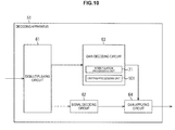
- the decoding apparatus 51 When limiting processing is performed on the gain value, the decoding apparatus 51 is configured as illustrated in, for example, FIG. 10 . It should be noted that, in FIG. 10 , the same reference numerals as those in FIG. 7 are assigned to portions corresponding to those in FIG. 7 , and explanation thereof will be omitted as appropriate.
- the decoding apparatus 51 illustrated in FIG. 10 has a different configuration from that of the decoding apparatus 51 in FIG. 7 in that a limiting processing unit 101 is newly provided at the gain decoding circuit 63, and has the same configuration as that of the decoding apparatus 51 in FIG. 7 in other points.
- the limiting processing unit 101 performs limiting processing on the gain value calculated through non-linear interpolation performed by the interpolation processing unit 71 to obtain a final gain value.
- the decoding processing described with reference to FIG. 8 is performed.
- the gain decoding processing illustrated in FIG. 11 is performed.
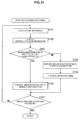
- the gain decoding processing by the decoding apparatus 51 in FIG. 10 will be described below with reference to the flowchart of FIG. 11 .
- step S101 to step S105 is the same as processing from step S71 to step S75 in FIG. 9 , explanation thereof will be omitted.
- step S106 the limiting processing unit 101 changes the gain value as appropriate so that the gain value does not become a negative value by performing calculation of the above-described equation (11) on the gain value at each sample position obtained through processing in step S105.
- the limiting processing unit 101 obtains a final gain value by further performing calculation of either equation (12) or equation (13) on the gain value limited through calculation of equation (11) according to the limiting information included in the gain code string.
- the limiting processing unit 101 performs calculation of equation (12) so that the gain value does not become a value less than one.
- the limiting processing unit 101 performs calculation of equation (13) so that the gain value does not become a value greater than one.
- step S 107 When the gain waveform is generated through linear interpolation in step S 104 or limiting processing is performed in step S106, the processing in step S 107 is performed, and the gain decoding processing ends. Because the processing in step S107 is the same as the processing in step S76 in FIG. 9 , explanation thereof will be omitted.
- the decoding apparatus 51 performs limiting processing on the gain value obtained through non-linear interpolation. By this means, it is possible to perform gain adjustment (volume correction) with a more appropriate gain value. It is therefore possible to obtain sound with higher quality.
- FIG. 12 indicates a gain value on a vertical axis and a sample position on a horizontal axis.
- the k-th gain sample position G21 and the k+1-th gain sample position G22 are extracted, and the gain code string including gain values, sample lengths and gain inclination values at these gain sample positions is obtained.
- an arrow D21 indicates a gain inclination value s[k] at the gain sample position G21
- an arrow D22 indicates a gain inclination value s[k+1] at the gain sample position G22.
- the straight line l[k] is a straight line which passes through the k-th gain sample position (point) on the gain waveform and which has inclination indicated with the gain inclination value s[k]. That is, when a value of the coordinate in the sample axis direction is the same as a value of the k-th gain sample position, the straight line 1[k] is a straight line which has a gain value g[k] at the k-th gain sample position as the value of the coordinate in the gain axis direction and which has inclination indicated with the gain inclination value s[k].
- the straight line 1[k+1] is a straight line which passes through the k+1-th gain sample position and which has inclination indicated with the gain inclination value s[k+1].
- d_sample[k] and d_sample[k+1] respectively indicate distances from the k-th gain sample position and the k+1-th gain sample position to the intersection X[k, k+1] in the sample axis direction.
- d_gain[k] and d_gain[k+1] respectively indicate distances from the k-th gain sample position and the k+1-th gain sample position to the intersection X[k, k+1] in the gain axis direction, that is, differences of the gain values.
- thre_sample and thre_gain respectively indicate a threshold of a distance in the sample axis direction and a threshold of a distance in the gain axis direction.
- equation (14) when the distance d_sample[k] is equal to or less than thre_sample, and the distance d_gain[k] is equal to or less than thre_gain, or when the distance d_sample[k+1] is equal to or less than thre_sample and the distance d_gain[k+1] is equal to or less than the threshold thre_gain, a distance from the gain sample position to the intersection X[k, k+1] is equal to or less than a threshold.
- the distance d_sample[k], the distance d_gain[k], the distance d_sample[k+1] and the distance d_gain[k+1] in equation (14) are respectively obtained using the following equation (15) to equation (18).
- d_sample k abs g k + 1 ⁇ g k ⁇ s k + 1 ⁇ T k / s k ⁇ s k + 1 [Math. 16]
- d_gain k abs s k ⁇ g k + 1 ⁇ g k ⁇ s k + 1 ⁇ T k / s k ⁇ s k + 1 [Math. 17]
- d_sample k + 1 abs g k + 1 ⁇ g k ⁇ s k + 1 ⁇ T k / s k ⁇ s k + 1 ⁇ T k [Math.
- d_gain k + 1 abs s k ⁇ g k + 1 ⁇ g k ⁇ s k + 1 ⁇ T k / s k ⁇ s k + 1 + g k ⁇ g k + 1
- abs(x) indicates that an absolute value of x is obtained.
- FIG. 13 indicates a gain value on a vertical axis and a sample position within a frame of the time series signal on a horizontal axis.
- the gain sample position G31 indicates the k-th gain sample position
- the arrow D31 indicates the gain inclination value s[k] at the gain sample position G31. Therefore, the straight line L51 is a straight line l[k].
- the gain sample position G32 indicates the k+1-th gain sample position
- the arrow D32 indicates the gain inclination value s[k+1] at the gain sample position G32. Therefore, the straight line L52 is a straight line 1[k+1].
- the intersection CP11 which is an intersection of the straight line L51 and the straight line L52 is an intersection X[k, k+1].
- the region TR11 has the gain sample position G31 in the center and has a length in a vertical direction of 2 ⁇ thre_gain, and a length in a horizontal direction of 2 ⁇ thre_sample in the drawing.
- the region TR12 has the gain sample position G21 in the center and, has a length in a vertical direction of 2 ⁇ thre_gain and a length in a horizontal direction of 2 ⁇ thre_sample in the drawing.
- the original gain waveform to be reproduced should have been a waveform close to a waveform constituted with the straight line L51 and the straight line L52. That is, in more detail, the waveform should have been close to the straight line L51 from the gain sample position G31 to the intersection CP11, and should have been close to the straight line L52 from the intersection CP11 to the gain sample position G32.
- the intersection CP11 is located within the region TR12, and a distance between the intersection CP11 to the gain sample position G32 is sufficiently short, it is possible to determine that the original gain waveform is approximated as a straight line connecting the gain sample position G31 and the gain sample position G32.
- the gain value can substantially linearly change, it is possible to reproduce the gain waveform with higher precision by obtaining the gain waveform through linear interpolation rather than obtaining the gain waveform through non-linear interpolation. Therefore, in the present technology, when the conditional expression indicated with the above-described equation (14) holds true, the gain waveform is obtained through linear interpolation.
- a gain value at each sample position between the gain sample position G31 and the gain sample position G32 is obtained through linear interpolation, and, by this means, for example, a gain waveform illustrated in FIG. 14 can be obtained.
- FIG. 14 the same reference numerals as those in FIG. 13 are assigned to portions corresponding to those in FIG. 13 , and explanation thereof will be omitted as appropriate.
- a straight line L61 connecting the gain sample position G31 and the gain sample position G32 is obtained as a gain waveform between the gain sample position G31 and the gain sample position G32.
- equation (14) holds true, and a straight line connecting the gain sample position G21 and the gain sample position G22 is set as a gain waveform between the gain sample positions. Therefore, in this example, the original gain waveform is accurately reproduced.
- the decoding apparatus 51 is configured as illustrated in, for example, FIG. 15 . It should be noted that, in FIG. 15 , the same reference numerals as those in FIG. 7 are assigned to portions corresponding to those in FIG. 7 , and explanation thereof will be omitted as appropriate.
- the decoding apparatus 51 illustrated in FIG. 15 has a different configuration from that of the decoding apparatus 51 in FIG. 7 in that an operation unit 131 is newly provided at the gain decoding circuit 63 and has the same configuration as that of the decoding apparatus 51 in FIG. 7 in other points.
- the operation unit 131 performs calculation of the above-described conditional expression indicated with equation (14).
- the gain encoding processing in step S 13 the gain code string only including the gain information and not including the interpolation mode information is generated, and the output code string obtained through multiplexing is outputted. Further, in this case, the gain information always includes the gain inclination value.
- the decoding processing described with reference to FIG. 8 is performed. However, in the gain decoding processing corresponding to step S43, the gain decoding processing illustrated in FIG. 16 is performed.
- the gain decoding processing by the decoding apparatus 51 in FIG. 15 will be described below with reference to the flowchart of FIG. 16 .
- step S131 is the same as the processing in step S71 in FIG. 9 , explanation thereof will be omitted.
- step S 132 the operation unit 131 calculates the conditional expression indicated with equation (14) based on the read-out gain information.
- the operation unit 131 performs the same calculation as the above-described equation (15) to equation (18) based on the gain value, the sample length and the gain inclination value at the gain sample position read out as the gain information.
- the operation unit 131 then performs calculation of equation (14) based on a distance from the gain sample position obtained as a result of the calculation to the intersection X[k, k+1].
- This calculation of equation (15) to equation (18) is equivalent to obtaining the straight line l[k] and the straight line 1[k+1] and obtaining the intersection X[k, k+1] of these straight lines and, further, obtaining differences between the gain values at the k-th gain sample position and the k+1-th gain sample position and the gain value at the intersection X[k, k+1]. Further, calculation of the conditional expression of equation (14) is equivalent to determining whether or not the differences between the gain values at the gain sample positions and the gain value at the intersection X[k, k+1] are equal to or less than a predetermined threshold.
- the decoding apparatus 51 it is possible to obtain a gain value at each sample position between the two gain sample positions through linear interpolation or non-linear interpolation according to the differences between the gain values at the gain sample positions and the gain value at the intersection X[k, k+1].
- step S133 the interpolation processing unit 71 determines whether or not linear interpolation is performed based on a calculation result of the conditional expression in step S132. For example, when the conditional expression indicated with equation (14) holds true, it is determined that linear interpolation is performed.
- step S 134 the interpolation processing unit 71 performs linear interpolation to generate a gain waveform, and, then, the processing proceeds to step S136.
- step S134 the same processing as the processing in step S74 in FIG. 9 is performed.
- step S135 the interpolation processing unit 71 performs non-linear interpolation to generate a gain waveform, and, then, the processing proceeds to step S136. It should be noted that, in step S135, the same processing as the processing in step S75 in FIG. 9 is performed.
- step S136 When the gain waveform is generated in step S 134 or step S 135, the processing in step S136 is performed, and the gain decoding processing ends. Because the processing in step S136 is the same as the processing in step S76 in FIG. 9 , explanation thereof will be omitted.
- the decoding apparatus 51 generates a gain waveform through linear interpolation under specific conditions. By this means, it is possible to obtain the original gain waveform with higher precision with a less processing amount and it is possible to reduce a code amount of the output code string.
- a gain value at each sample position between two gain sample positions is calculated through linear interpolation using equation (1).
- a waveform constituted with straight lines respectively connecting the intersection CP11 of the two straight line L51 and straight line L52 as illustrated in FIG. 17 and two gain sample positions is set as a gain waveform obtained through linear interpolation.
- a broken line L71 constituted with a straight line connecting the gain sample position G31 and the intersection CP11 and a straight line connecting the gain sample position G32 and the intersection CP11 is set as a gain waveform between the gain sample position G31 and the gain sample position G32.
- the broken line L71 is set as the gain waveform by utilizing the intersection CP11, by only setting two positions of the gain sample position G31 and the gain sample position G32 as the gain sample positions, it is possible to make a difference between the gain waveform before encoded and the gain waveform obtained through decoding smaller. Therefore, in a method in which linear interpolation is performed while utilizing the intersection, it is possible to reduce the number of gain sample positions, and thereby it is possible to suppress a bit rate of the output code string and improve coding efficiency.
- intersection CP11 has to be located between the gain sample position G31 and the gain sample position G32 in the sample axis direction.
- a region used for determining whether non-linear interpolation is performed or linear interpolation is performed is different between the example in FIG. 13 and the example in FIG. 17 .
- the intersection CP11 is included in either the region TR21 or the region TR22, linear interpolation utilizing the intersection is performed.
- the region TR21 is a right half region of the region TR11 illustrated in FIG. 13 , that is, a region at the right side of the region TR11 with respect to the gain sample position G31 in FIG. 13 .
- the region TR22 is a left half region of the region TR12 illustrated in FIG. 13 , that is, a region at the left side of the region TR12 with respect to the gain sample position G32 in FIG. 13 .
- the distance d_sample[k], the distance d_gain[k], the distance d_sample[k+1] and the distance d_gain[k+1] in equation (19) are respectively obtained using the following equation (20) to equation (23).
- d_sample k g k + 1 ⁇ g k ⁇ s k + 1 ⁇ T k / s k ⁇ s k + 1 [Math.
- d_gain k + 1 abs s k ⁇ g k + 1 ⁇ g k ⁇ s k + 1 ⁇ T k / s k ⁇ s k + 1 + g k ⁇ g k + 1
- T ′ k g k + 1 ⁇ g k ⁇ s k + 1 ⁇ T k / s k ⁇ s k + 1
- a gain value g_interpolated[n] of the sample n which is located between the k-th gain sample position and the intersection X[k, k+1] and which is the n-th (where 0 ⁇ n ⁇ T'[k]) sample from the head of the frame is calculated from the following equation (25).
- g_interpolated n a 1 k ⁇ n + b 1 k 0 ⁇ n ⁇ T ′ k
- a1[k] and b1[k] are values respectively obtained from the following equation (26) and equation (27).
- [Math. 26] a 1 k s k
- a gain value g_interpolated[n] of the sample n which is located between the intersection X[k, k+1] and the k+1-th gain sample position and which is the n-th (where T'[k] ⁇ n ⁇ T[k]) sample from the head of the frame is calculated from the following equation (28).
- g_interpolated n a 2 k ⁇ n + b 2 k T ′ k ⁇ n ⁇ T k
- a2[k] and b2[k] are values respectively obtained from the following equation (29) and equation (30).
- [Math. 29] a 2 k s k + 1
- the operation unit 131 performs calculation of the conditional expression indicated with equation (19) based on the read-out gain information in step S132.
- step S 134 the interpolation processing unit 71 calculates the sample position T'[k] of the intersection X[k, k+1] using equation (24) based on the gain value, the sample length and the gain inclination value at the gain sample position read out as the gain information. Further, the interpolation processing unit 71 performs calculation of equation (25) and equation (28) using the obtained sample position T'[k] and generates a gain waveform through linear interpolation.
- step S135 the interpolation processing unit 71 performs non-linear interpolation to generate a gain waveform.
- both linear interpolation and non-linear interpolation can be performed only with a scheme in which non-linear interpolation is performed, it becomes unnecessary to include the interpolation mode information in the gain code string, so that it is possible to lower a bit rate of the output code string. That is, it is possible to reduce a code amount of the output code string.
- the interpolation mode information is included in the gain code string, and the gain waveform is basically obtained using an interpolation scheme indicated in the interpolation mode information
- the interpolation scheme indicated in the interpolation mode information is a scheme using non-linear interpolation
- linear interpolation may be performed under specific conditions.
- the decoding processing described with reference to FIG. 8 is performed at the decoding apparatus 51.
- the gain decoding processing illustrated in FIG. 18 is performed at the decoding apparatus 51.
- the gain decoding processing by the decoding apparatus 51 in FIG. 15 will be described below with reference to the flowchart of FIG. 18 .
- step S161 to step S164 is the same as the processing in step S71 to step S74 in FIG. 9 , explanation thereof will be omitted.
- step S163 when it is determined that the scheme is a scheme using non-linear interpolation, in step S165, the operation unit 131 performs calculation of the conditional expression indicated with equation (14) based on the read-out gain information.
- step S166 to step S168 because these processing is the same as the processing in step S133 to step S135 in FIG. 16 , explanation thereof will be omitted. It should be noted that, from step S 165 to step S168, the processing described in the third embodiment may be performed, or processing described in modified example 1 of the third embodiment may be performed. Further, when non-linear interpolation is performed, limiting processing may be performed.
- step S164 When a gain waveform is generated through interpolation in step S164, step S 167 or step S168, the processing then proceeds to step S169.
- step S169 the gain decoding circuit 63 determines whether or not processing is performed for all the gain sample positions.
- step S169 When it is determined in step S169 that not all of the gain sample positions is processed, the processing returns to step S161, and the above-described processing is repeated.
- step S169 when it is determined in step S169 that all of the gain sample positions are processed, the gain decoding circuit 63 supplies the gain waveform corresponding to one frame constituted with gain values at the sample positions obtained through the processing so far to the gain applying circuit 64, and the gain decoding processing ends.
- the processing then proceeds to step S44 in FIG. 8 .
- the decoding apparatus 51 obtains a gain waveform through linear interpolation or non-linear interpolation according to the interpolation mode information.
- the gain waveform through non-linear interpolation as appropriate in this manner according to the interpolation mode information, it is possible to reproduce a gain waveform with high precision with a less code amount.
- the interpolation scheme indicated in the interpolation mode information is a scheme using non-linear interpolation
- by performing linear interpolation under specific conditions it is possible to reproduce the original gain waveform with higher precision with a less processing amount of encoding. Further, it is possible to reduce a code amount of the output code string.
- the series of processes described above can be executed by hardware but can also be executed by software.
- a program that constructs such software is installed into a computer.
- the expression "computer” includes a computer in which dedicated hardware is incorporated and a general-purpose personal computer or the like that is capable of executing various functions when various programs are installed.
- FIG. 19 is a block diagram showing a hardware configuration example of a computer that performs the above-described series of processing using a program.
- a CPU Central Processing Unit
- ROM Read Only Memory
- RAM Random Access Memory
- An input/output interface 505 is also connected to the bus 504.
- An input unit 506, an output unit 507, a recording unit 508, a communication unit 509, and a drive 510 are connected to the input/output interface 505.
- the input unit 506 is configured from a keyboard, a mouse, a microphone, an imaging device or the like.
- the output unit 507 is configured from a display, a speaker or the like.
- the recording unit 508 is configured from a hard disk, a nonvolatile memory or the like.
- the communication unit 509 is configured from a network interface or the like.
- the drive 510 drives a removable medium 511 such as a magnetic disk, an optical disk, a magneto-optical disk, a semiconductor memory or the like.
- the CPU 501 loads a program recorded in the recording unit 508 via the input/output interface 505 and the bus 504 into the RAM 503 and executes the program to carry out the series of processes described earlier.
- Programs to be executed by the computer are provided being recorded in the removable medium 511 which is a packaged medium or the like. Also, programs may be provided via a wired or wireless transmission medium, such as a local area network, the Internet or digital satellite broadcasting.
- the program can be installed into the recording unit 508 via the input/output interface 505. It is also possible to receive the program from a wired or wireless transfer medium using the communication unit 509 and install the program into the recording unit 508. As another alternative, the program can be installed in advance into the ROM 502 or the recording unit 508.
- program executed by a computer may be a program that is processed in time series according to the sequence described in this specification or a program that is processed in parallel or at necessary timing such as upon calling.
- the present technology can adopt a configuration of cloud computing which processes by allocating and connecting one function by a plurality of apparatuses through a network.
- each step described by the above mentioned flow charts can be executed by one apparatus or by allocating a plurality of apparatuses.
- the plurality of processes included in this one step can be executed by one apparatus or by allocating a plurality of apparatuses.
- present technology may also be configured as below.
Landscapes
- Engineering & Computer Science (AREA)
- Physics & Mathematics (AREA)
- Multimedia (AREA)
- Computational Linguistics (AREA)
- Signal Processing (AREA)
- Health & Medical Sciences (AREA)
- Audiology, Speech & Language Pathology (AREA)
- Human Computer Interaction (AREA)
- Acoustics & Sound (AREA)
- Spectroscopy & Molecular Physics (AREA)
- Theoretical Computer Science (AREA)
- Compression, Expansion, Code Conversion, And Decoders (AREA)
- Stereophonic System (AREA)
- Transmission Systems Not Characterized By The Medium Used For Transmission (AREA)
Priority Applications (1)
| Application Number | Priority Date | Filing Date | Title |
|---|---|---|---|
| EP19199358.3A EP3608909B1 (de) | 2013-12-27 | 2014-12-12 | Decodierungsvorrichtung und -verfahren und programm |
Applications Claiming Priority (2)
| Application Number | Priority Date | Filing Date | Title |
|---|---|---|---|
| JP2013272943 | 2013-12-27 | ||
| PCT/JP2014/082925 WO2015098564A1 (ja) | 2013-12-27 | 2014-12-12 | 復号化装置および方法、並びにプログラム |
Related Child Applications (1)
| Application Number | Title | Priority Date | Filing Date |
|---|---|---|---|
| EP19199358.3A Division EP3608909B1 (de) | 2013-12-27 | 2014-12-12 | Decodierungsvorrichtung und -verfahren und programm |
Publications (3)
| Publication Number | Publication Date |
|---|---|
| EP3089161A1 true EP3089161A1 (de) | 2016-11-02 |
| EP3089161A4 EP3089161A4 (de) | 2017-07-12 |
| EP3089161B1 EP3089161B1 (de) | 2019-10-23 |
Family
ID=53478428
Family Applications (2)
| Application Number | Title | Priority Date | Filing Date |
|---|---|---|---|
| EP14873206.8A Active EP3089161B1 (de) | 2013-12-27 | 2014-12-12 | Decodierungsvorrichtung, -verfahren und -programm |
| EP19199358.3A Active EP3608909B1 (de) | 2013-12-27 | 2014-12-12 | Decodierungsvorrichtung und -verfahren und programm |
Family Applications After (1)
| Application Number | Title | Priority Date | Filing Date |
|---|---|---|---|
| EP19199358.3A Active EP3608909B1 (de) | 2013-12-27 | 2014-12-12 | Decodierungsvorrichtung und -verfahren und programm |
Country Status (14)
| Country | Link |
|---|---|
| US (4) | US10692511B2 (de) |
| EP (2) | EP3089161B1 (de) |
| JP (4) | JP6593173B2 (de) |
| KR (4) | KR102761176B1 (de) |
| CN (1) | CN105849801B (de) |
| AU (1) | AU2014371411A1 (de) |
| BR (1) | BR112016014476B1 (de) |
| CA (3) | CA3162763C (de) |
| MX (1) | MX2016008172A (de) |
| MY (1) | MY188538A (de) |
| RU (2) | RU2764260C2 (de) |
| SG (1) | SG11201605015XA (de) |
| TW (1) | TWI644308B (de) |
| WO (1) | WO2015098564A1 (de) |
Cited By (17)
| Publication number | Priority date | Publication date | Assignee | Title |
|---|---|---|---|---|
| US10070243B2 (en) | 2013-09-12 | 2018-09-04 | Dolby Laboratories Licensing Corporation | Loudness adjustment for downmixed audio content |
| US10074379B2 (en) | 2012-05-18 | 2018-09-11 | Dolby Laboratories Licensing Corporation | System for maintaining reversible dynamic range control information associated with parametric audio coders |
| US10095468B2 (en) | 2013-09-12 | 2018-10-09 | Dolby Laboratories Licensing Corporation | Dynamic range control for a wide variety of playback environments |
| US10311891B2 (en) | 2012-03-23 | 2019-06-04 | Dolby Laboratories Licensing Corporation | Post-processing gains for signal enhancement |
| US10340869B2 (en) | 2004-10-26 | 2019-07-02 | Dolby Laboratories Licensing Corporation | Adjusting dynamic range of an audio signal based on one or more dynamic equalization and/or dynamic range control parameters |
| US10349125B2 (en) | 2013-04-05 | 2019-07-09 | Dolby Laboratories Licensing Corporation | Method and apparatus for enabling a loudness controller to adjust a loudness level of a secondary media data portion in a media content to a different loudness level |
| US10360919B2 (en) | 2013-02-21 | 2019-07-23 | Dolby International Ab | Methods for parametric multi-channel encoding |
| US10411669B2 (en) | 2013-03-26 | 2019-09-10 | Dolby Laboratories Licensing Corporation | Volume leveler controller and controlling method |
| US10418045B2 (en) | 2010-02-11 | 2019-09-17 | Dolby Laboratories Licensing Corporation | System and method for non-destructively normalizing loudness of audio signals within portable devices |
| US10453467B2 (en) | 2014-10-10 | 2019-10-22 | Dolby Laboratories Licensing Corporation | Transmission-agnostic presentation-based program loudness |
| US10594283B2 (en) | 2014-05-26 | 2020-03-17 | Dolby Laboratories Licensing Corporation | Audio signal loudness control |
| US10672413B2 (en) | 2013-01-21 | 2020-06-02 | Dolby Laboratories Licensing Corporation | Decoding of encoded audio bitstream with metadata container located in reserved data space |
| US10671339B2 (en) | 2013-01-21 | 2020-06-02 | Dolby Laboratories Licensing Corporation | System and method for optimizing loudness and dynamic range across different playback devices |
| US11404071B2 (en) | 2013-06-19 | 2022-08-02 | Dolby Laboratories Licensing Corporation | Audio encoder and decoder with dynamic range compression metadata |
| US11708741B2 (en) | 2012-05-18 | 2023-07-25 | Dolby Laboratories Licensing Corporation | System for maintaining reversible dynamic range control information associated with parametric audio coders |
| RU2859838C1 (ru) * | 2018-04-25 | 2026-04-08 | Долби Интернешнл Аб | Интеграция методик реконструкции высоких частот звука |
| US12603094B2 (en) | 2010-12-03 | 2026-04-14 | Dolby Laboratories Licensing Corporation | Adaptive processing with multiple media processing nodes |
Families Citing this family (5)
| Publication number | Priority date | Publication date | Assignee | Title |
|---|---|---|---|---|
| JP5850216B2 (ja) | 2010-04-13 | 2016-02-03 | ソニー株式会社 | 信号処理装置および方法、符号化装置および方法、復号装置および方法、並びにプログラム |
| JP5743137B2 (ja) | 2011-01-14 | 2015-07-01 | ソニー株式会社 | 信号処理装置および方法、並びにプログラム |
| US10692511B2 (en) | 2013-12-27 | 2020-06-23 | Sony Corporation | Decoding apparatus and method, and program |
| CN110312146B (zh) | 2019-06-06 | 2021-11-09 | 百度在线网络技术(北京)有限公司 | 音频处理方法、装置、电子设备和存储介质 |
| KR20190085889A (ko) | 2019-06-28 | 2019-07-19 | 신원제 | 태양광 패널 청소기 |
Family Cites Families (248)
| Publication number | Priority date | Publication date | Assignee | Title |
|---|---|---|---|---|
| US4628529A (en) | 1985-07-01 | 1986-12-09 | Motorola, Inc. | Noise suppression system |
| US4817151A (en) * | 1987-11-09 | 1989-03-28 | Broadcast Technology Partners | Selective decoder for compatible FM stereophonic system utilizing companding of difference signal |
| JPH0364800A (ja) | 1989-08-03 | 1991-03-20 | Ricoh Co Ltd | 音声符号化及び復号化方式 |
| JPH03254223A (ja) | 1990-03-02 | 1991-11-13 | Eastman Kodak Japan Kk | アナログデータ伝送方式 |
| US5267317A (en) * | 1991-10-18 | 1993-11-30 | At&T Bell Laboratories | Method and apparatus for smoothing pitch-cycle waveforms |
| JP3137805B2 (ja) * | 1993-05-21 | 2001-02-26 | 三菱電機株式会社 | 音声符号化装置、音声復号化装置、音声後処理装置及びこれらの方法 |
| US6022222A (en) * | 1994-01-03 | 2000-02-08 | Mary Beth Guinan | Icon language teaching system |
| JP2655485B2 (ja) | 1994-06-24 | 1997-09-17 | 日本電気株式会社 | 音声セル符号化装置 |
| JP3498375B2 (ja) | 1994-07-20 | 2004-02-16 | ソニー株式会社 | ディジタル・オーディオ信号記録装置 |
| JP3189598B2 (ja) | 1994-10-28 | 2001-07-16 | 松下電器産業株式会社 | 信号合成方法および信号合成装置 |
| US5640490A (en) * | 1994-11-14 | 1997-06-17 | Fonix Corporation | User independent, real-time speech recognition system and method |
| US5664055A (en) * | 1995-06-07 | 1997-09-02 | Lucent Technologies Inc. | CS-ACELP speech compression system with adaptive pitch prediction filter gain based on a measure of periodicity |
| US5956674A (en) | 1995-12-01 | 1999-09-21 | Digital Theater Systems, Inc. | Multi-channel predictive subband audio coder using psychoacoustic adaptive bit allocation in frequency, time and over the multiple channels |
| US5749064A (en) * | 1996-03-01 | 1998-05-05 | Texas Instruments Incorporated | Method and system for time scale modification utilizing feature vectors about zero crossing points |
| JPH1020888A (ja) | 1996-07-02 | 1998-01-23 | Matsushita Electric Ind Co Ltd | 音声符号化・復号化装置 |
| US6073100A (en) | 1997-03-31 | 2000-06-06 | Goodridge, Jr.; Alan G | Method and apparatus for synthesizing signals using transform-domain match-output extension |
| SE512719C2 (sv) | 1997-06-10 | 2000-05-02 | Lars Gustaf Liljeryd | En metod och anordning för reduktion av dataflöde baserad på harmonisk bandbreddsexpansion |
| KR20000068538A (ko) | 1997-07-11 | 2000-11-25 | 이데이 노부유끼 | 정보 복호 방법 및 장치, 정보 부호화 방법 및 장치, 및 제공매체 |
| US5913194A (en) * | 1997-07-14 | 1999-06-15 | Motorola, Inc. | Method, device and system for using statistical information to reduce computation and memory requirements of a neural network based speech synthesis system |
| JPH11168622A (ja) * | 1997-12-05 | 1999-06-22 | Canon Inc | 画像処理装置、画像処理方法および記憶媒体 |
| SE9903553D0 (sv) | 1999-01-27 | 1999-10-01 | Lars Liljeryd | Enhancing percepptual performance of SBR and related coding methods by adaptive noise addition (ANA) and noise substitution limiting (NSL) |
| JP3696091B2 (ja) | 1999-05-14 | 2005-09-14 | 松下電器産業株式会社 | オーディオ信号の帯域を拡張するための方法及び装置 |
| JP4218134B2 (ja) * | 1999-06-17 | 2009-02-04 | ソニー株式会社 | 復号装置及び方法、並びにプログラム提供媒体 |
| US6904405B2 (en) * | 1999-07-17 | 2005-06-07 | Edwin A. Suominen | Message recognition using shared language model |
| US6691082B1 (en) * | 1999-08-03 | 2004-02-10 | Lucent Technologies Inc | Method and system for sub-band hybrid coding |
| JP3454206B2 (ja) | 1999-11-10 | 2003-10-06 | 三菱電機株式会社 | 雑音抑圧装置及び雑音抑圧方法 |
| CA2290037A1 (en) | 1999-11-18 | 2001-05-18 | Voiceage Corporation | Gain-smoothing amplifier device and method in codecs for wideband speech and audio signals |
| EP1258078B1 (de) * | 2000-02-24 | 2004-03-17 | Fraunhofer-Gesellschaft zur Förderung der angewandten Forschung e.V. | Vorrichtung zur beurteilung der nichtlinearen kennlinie eines verstärkers |
| US6782366B1 (en) * | 2000-05-15 | 2004-08-24 | Lsi Logic Corporation | Method for independent dynamic range control |
| SE0004163D0 (sv) | 2000-11-14 | 2000-11-14 | Coding Technologies Sweden Ab | Enhancing perceptual performance of high frequency reconstruction coding methods by adaptive filtering |
| US20040054525A1 (en) * | 2001-01-22 | 2004-03-18 | Hiroshi Sekiguchi | Encoding method and decoding method for digital voice data |
| JP2002268698A (ja) | 2001-03-08 | 2002-09-20 | Nec Corp | 音声認識装置と標準パターン作成装置及び方法並びにプログラム |
| SE0101175D0 (sv) | 2001-04-02 | 2001-04-02 | Coding Technologies Sweden Ab | Aliasing reduction using complex-exponential-modulated filterbanks |
| JP4231987B2 (ja) | 2001-06-15 | 2009-03-04 | 日本電気株式会社 | 音声符号化復号方式間の符号変換方法、その装置、そのプログラム及び記憶媒体 |
| US7174135B2 (en) | 2001-06-28 | 2007-02-06 | Koninklijke Philips Electronics N. V. | Wideband signal transmission system |
| SE0202159D0 (sv) * | 2001-07-10 | 2002-07-09 | Coding Technologies Sweden Ab | Efficientand scalable parametric stereo coding for low bitrate applications |
| DE60230856D1 (de) | 2001-07-13 | 2009-03-05 | Panasonic Corp | Audiosignaldecodierungseinrichtung und audiosignalcodierungseinrichtung |
| US6895375B2 (en) | 2001-10-04 | 2005-05-17 | At&T Corp. | System for bandwidth extension of Narrow-band speech |
| US6988066B2 (en) | 2001-10-04 | 2006-01-17 | At&T Corp. | Method of bandwidth extension for narrow-band speech |
| CN100395817C (zh) | 2001-11-14 | 2008-06-18 | 松下电器产业株式会社 | 编码设备、解码设备和解码方法 |
| JP3926726B2 (ja) | 2001-11-14 | 2007-06-06 | 松下電器産業株式会社 | 符号化装置および復号化装置 |
| DE60202881T2 (de) | 2001-11-29 | 2006-01-19 | Coding Technologies Ab | Wiederherstellung von hochfrequenzkomponenten |
| US7013011B1 (en) * | 2001-12-28 | 2006-03-14 | Plantronics, Inc. | Audio limiting circuit |
| CN1288625C (zh) | 2002-01-30 | 2006-12-06 | 松下电器产业株式会社 | 音频编码与解码设备及其方法 |
| JP3815347B2 (ja) * | 2002-02-27 | 2006-08-30 | ヤマハ株式会社 | 歌唱合成方法と装置及び記録媒体 |
| JP2003255973A (ja) | 2002-02-28 | 2003-09-10 | Nec Corp | 音声帯域拡張システムおよび方法 |
| US20030187663A1 (en) | 2002-03-28 | 2003-10-02 | Truman Michael Mead | Broadband frequency translation for high frequency regeneration |
| JP2003316394A (ja) | 2002-04-23 | 2003-11-07 | Nec Corp | 音声復号システム、及び、音声復号方法、並びに、音声復号プログラム |
| US7447631B2 (en) | 2002-06-17 | 2008-11-04 | Dolby Laboratories Licensing Corporation | Audio coding system using spectral hole filling |
| BRPI0311601B8 (pt) | 2002-07-19 | 2018-02-14 | Matsushita Electric Industrial Co Ltd | "aparelho e método decodificador de áudio" |
| JP4728568B2 (ja) | 2002-09-04 | 2011-07-20 | マイクロソフト コーポレーション | レベル・モードとラン・レングス/レベル・モードの間での符号化を適応させるエントロピー符号化 |
| JP3881943B2 (ja) | 2002-09-06 | 2007-02-14 | 松下電器産業株式会社 | 音響符号化装置及び音響符号化方法 |
| SE0202770D0 (sv) | 2002-09-18 | 2002-09-18 | Coding Technologies Sweden Ab | Method for reduction of aliasing introduces by spectral envelope adjustment in real-valued filterbanks |
| ATE318405T1 (de) | 2002-09-19 | 2006-03-15 | Matsushita Electric Industrial Co Ltd | Audiodecodierungsvorrichtung und -verfahren |
| US7330812B2 (en) | 2002-10-04 | 2008-02-12 | National Research Council Of Canada | Method and apparatus for transmitting an audio stream having additional payload in a hidden sub-channel |
| US7827312B2 (en) * | 2002-12-27 | 2010-11-02 | The Nielsen Company (Us), Llc | Methods and apparatus for transcoding metadata |
| EP1611772A1 (de) | 2003-03-04 | 2006-01-04 | Nokia Corporation | Träger für eine mehrkanalaudioerweiterung |
| US7020448B2 (en) * | 2003-03-07 | 2006-03-28 | Conwise Technology Corporation Ltd. | Method for detecting a tone signal through digital signal processing |
| CN1458646A (zh) * | 2003-04-21 | 2003-11-26 | 北京阜国数字技术有限公司 | 一种滤波参数矢量量化和结合量化模型预测的音频编码方法 |
| US7318035B2 (en) | 2003-05-08 | 2008-01-08 | Dolby Laboratories Licensing Corporation | Audio coding systems and methods using spectral component coupling and spectral component regeneration |
| US20050004793A1 (en) | 2003-07-03 | 2005-01-06 | Pasi Ojala | Signal adaptation for higher band coding in a codec utilizing band split coding |
| US7277537B2 (en) * | 2003-09-02 | 2007-10-02 | Texas Instruments Incorporated | Tone, modulated tone, and saturated tone detection in a voice activity detection device |
| KR20050027179A (ko) | 2003-09-13 | 2005-03-18 | 삼성전자주식회사 | 오디오 데이터 복원 방법 및 그 장치 |
| US7844451B2 (en) | 2003-09-16 | 2010-11-30 | Panasonic Corporation | Spectrum coding/decoding apparatus and method for reducing distortion of two band spectrums |
| CN100507485C (zh) | 2003-10-23 | 2009-07-01 | 松下电器产业株式会社 | 频谱编码装置和频谱解码装置 |
| KR100587953B1 (ko) | 2003-12-26 | 2006-06-08 | 한국전자통신연구원 | 대역-분할 광대역 음성 코덱에서의 고대역 오류 은닉 장치 및 그를 이용한 비트스트림 복호화 시스템 |
| US7148415B2 (en) * | 2004-03-19 | 2006-12-12 | Apple Computer, Inc. | Method and apparatus for evaluating and correcting rhythm in audio data |
| AU2005241905A1 (en) * | 2004-04-21 | 2005-11-17 | Dolby Laboratories Licensing Corporation | Audio bitstream format in which the bitstream syntax is described by an ordered transversal of a tree hierarchy data structure |
| EP1744139B1 (de) | 2004-05-14 | 2015-11-11 | Panasonic Intellectual Property Corporation of America | Dekodierungsvorrichtung und verfahren dafür |
| US8463602B2 (en) | 2004-05-19 | 2013-06-11 | Panasonic Corporation | Encoding device, decoding device, and method thereof |
| ATE474310T1 (de) | 2004-05-28 | 2010-07-15 | Nokia Corp | Mehrkanalige audio-erweiterung |
| US20060018457A1 (en) * | 2004-06-25 | 2006-01-26 | Takahiro Unno | Voice activity detectors and methods |
| KR100608062B1 (ko) | 2004-08-04 | 2006-08-02 | 삼성전자주식회사 | 오디오 데이터의 고주파수 복원 방법 및 그 장치 |
| TWI294119B (en) * | 2004-08-18 | 2008-03-01 | Sunplus Technology Co Ltd | Dvd player with sound learning function |
| WO2007120453A1 (en) * | 2006-04-04 | 2007-10-25 | Dolby Laboratories Licensing Corporation | Calculating and adjusting the perceived loudness and/or the perceived spectral balance of an audio signal |
| US7716046B2 (en) | 2004-10-26 | 2010-05-11 | Qnx Software Systems (Wavemakers), Inc. | Advanced periodic signal enhancement |
| US20060106620A1 (en) | 2004-10-28 | 2006-05-18 | Thompson Jeffrey K | Audio spatial environment down-mixer |
| SE0402651D0 (sv) | 2004-11-02 | 2004-11-02 | Coding Tech Ab | Advanced methods for interpolation and parameter signalling |
| ES2791001T3 (es) | 2004-11-02 | 2020-10-30 | Koninklijke Philips Nv | Codificación y decodificación de señales de audio mediante el uso de bancos de filtros de valor complejo |
| EP1798724B1 (de) | 2004-11-05 | 2014-06-18 | Panasonic Corporation | Kodierer, dekodierer, kodiermethode und dekodiermethode |
| RU2404506C2 (ru) | 2004-11-05 | 2010-11-20 | Панасоник Корпорэйшн | Устройство масштабируемого декодирования и устройство масштабируемого кодирования |
| US7873515B2 (en) * | 2004-11-23 | 2011-01-18 | Stmicroelectronics Asia Pacific Pte. Ltd. | System and method for error reconstruction of streaming audio information |
| KR100657916B1 (ko) | 2004-12-01 | 2006-12-14 | 삼성전자주식회사 | 주파수 대역간의 유사도를 이용한 오디오 신호 처리 장치및 방법 |
| US7616710B2 (en) * | 2004-12-08 | 2009-11-10 | Electronics And Telecommunications Research Institute | Frequency offset estimating method and receiver employing the same |
| US7676362B2 (en) * | 2004-12-31 | 2010-03-09 | Motorola, Inc. | Method and apparatus for enhancing loudness of a speech signal |
| EP1840874B1 (de) | 2005-01-11 | 2019-04-10 | NEC Corporation | Vorrichtung, verfahren und programm zur audiokodierung |
| KR100708121B1 (ko) | 2005-01-22 | 2007-04-16 | 삼성전자주식회사 | 음성 신호의 대역 확장 방법 및 장치 |
| BRPI0608270A2 (pt) | 2005-04-01 | 2009-10-06 | Qualcomm Inc | sistemas, métodos e equipamento para filtragem anti-dispersão |
| DE602006004959D1 (de) | 2005-04-15 | 2009-03-12 | Dolby Sweden Ab | Zeitliche hüllkurvenformgebung von entkorrelierten signalen |
| US7627481B1 (en) * | 2005-04-19 | 2009-12-01 | Apple Inc. | Adapting masking thresholds for encoding a low frequency transient signal in audio data |
| EP1898397B1 (de) * | 2005-06-29 | 2009-10-21 | Panasonic Corporation | Skalierbarer dekodierer und interpolationsverfahren für verschwundene daten |
| US20070005351A1 (en) | 2005-06-30 | 2007-01-04 | Sathyendra Harsha M | Method and system for bandwidth expansion for voice communications |
| JP4899359B2 (ja) | 2005-07-11 | 2012-03-21 | ソニー株式会社 | 信号符号化装置及び方法、信号復号装置及び方法、並びにプログラム及び記録媒体 |
| KR100813259B1 (ko) | 2005-07-13 | 2008-03-13 | 삼성전자주식회사 | 입력신호의 계층적 부호화/복호화 장치 및 방법 |
| JP4918490B2 (ja) | 2005-09-02 | 2012-04-18 | パナソニック株式会社 | エネルギー整形装置及びエネルギー整形方法 |
| US7653146B2 (en) * | 2005-09-06 | 2010-01-26 | Liquid Xstream Systems Inc. | System and method for delivery of video, content on demand and IP packets |
| RU2378790C1 (ru) * | 2005-09-27 | 2010-01-10 | Квэлкомм Инкорпорейтед | Методики масштабируемости на основе информации содержимого |
| US9820065B2 (en) | 2005-09-27 | 2017-11-14 | Ronald Quan | Method and apparatus to evaluate audio equipment for dynamic distortions and or differential phase and or frequency modulation effects |
| CN101273404B (zh) | 2005-09-30 | 2012-07-04 | 松下电器产业株式会社 | 语音编码装置以及语音编码方法 |
| KR20080047443A (ko) | 2005-10-14 | 2008-05-28 | 마츠시타 덴끼 산교 가부시키가이샤 | 변환 부호화 장치 및 변환 부호화 방법 |
| JP4950210B2 (ja) | 2005-11-04 | 2012-06-13 | ノキア コーポレイション | オーディオ圧縮 |
| EP2381440A3 (de) | 2005-11-30 | 2012-03-21 | Panasonic Corporation | Subbandcodierungsvorrichtung und Verfahren zum Codieren eines Subbands |
| JP4876574B2 (ja) | 2005-12-26 | 2012-02-15 | ソニー株式会社 | 信号符号化装置及び方法、信号復号装置及び方法、並びにプログラム及び記録媒体 |
| JP4863713B2 (ja) | 2005-12-29 | 2012-01-25 | 富士通株式会社 | 雑音抑制装置、雑音抑制方法、及びコンピュータプログラム |
| WO2007080211A1 (en) * | 2006-01-09 | 2007-07-19 | Nokia Corporation | Decoding of binaural audio signals |
| US8775526B2 (en) * | 2006-01-16 | 2014-07-08 | Zlango Ltd. | Iconic communication |
| US7953604B2 (en) | 2006-01-20 | 2011-05-31 | Microsoft Corporation | Shape and scale parameters for extended-band frequency coding |
| US7912628B2 (en) * | 2006-03-03 | 2011-03-22 | Inrix, Inc. | Determining road traffic conditions using data from multiple data sources |
| US7590523B2 (en) | 2006-03-20 | 2009-09-15 | Mindspeed Technologies, Inc. | Speech post-processing using MDCT coefficients |
| US20090248407A1 (en) | 2006-03-31 | 2009-10-01 | Panasonic Corporation | Sound encoder, sound decoder, and their methods |
| WO2007126015A1 (ja) | 2006-04-27 | 2007-11-08 | Panasonic Corporation | 音声符号化装置、音声復号化装置、およびこれらの方法 |
| ATE528750T1 (de) | 2006-05-10 | 2011-10-15 | Panasonic Corp | Kodierungsvorrichtung und -verfahren |
| JP2007316254A (ja) | 2006-05-24 | 2007-12-06 | Sony Corp | オーディオ信号補間方法及びオーディオ信号補間装置 |
| KR20070115637A (ko) | 2006-06-03 | 2007-12-06 | 삼성전자주식회사 | 대역폭 확장 부호화 및 복호화 방법 및 장치 |
| JP2007333785A (ja) | 2006-06-12 | 2007-12-27 | Matsushita Electric Ind Co Ltd | オーディオ信号符号化装置およびオーディオ信号符号化方法 |
| KR101244310B1 (ko) | 2006-06-21 | 2013-03-18 | 삼성전자주식회사 | 광대역 부호화 및 복호화 방법 및 장치 |
| WO2007148925A1 (en) | 2006-06-21 | 2007-12-27 | Samsung Electronics Co., Ltd. | Method and apparatus for adaptively encoding and decoding high frequency band |
| US8260609B2 (en) | 2006-07-31 | 2012-09-04 | Qualcomm Incorporated | Systems, methods, and apparatus for wideband encoding and decoding of inactive frames |
| WO2008032828A1 (en) | 2006-09-15 | 2008-03-20 | Panasonic Corporation | Audio encoding device and audio encoding method |
| GB2443027B (en) * | 2006-10-19 | 2009-04-01 | Sony Comp Entertainment Europe | Apparatus and method of audio processing |
| JP4918841B2 (ja) | 2006-10-23 | 2012-04-18 | 富士通株式会社 | 符号化システム |
| JP5141180B2 (ja) | 2006-11-09 | 2013-02-13 | ソニー株式会社 | 周波数帯域拡大装置及び周波数帯域拡大方法、再生装置及び再生方法、並びに、プログラム及び記録媒体 |
| US8295507B2 (en) | 2006-11-09 | 2012-10-23 | Sony Corporation | Frequency band extending apparatus, frequency band extending method, player apparatus, playing method, program and recording medium |
| KR101565919B1 (ko) | 2006-11-17 | 2015-11-05 | 삼성전자주식회사 | 고주파수 신호 부호화 및 복호화 방법 및 장치 |
| JP4930320B2 (ja) | 2006-11-30 | 2012-05-16 | ソニー株式会社 | 再生方法及び装置、プログラム並びに記録媒体 |
| EP2101322B1 (de) | 2006-12-15 | 2018-02-21 | III Holdings 12, LLC | Codierungseinrichtung, decodierungseinrichtung und verfahren dafür |
| RU2406166C2 (ru) * | 2007-02-14 | 2010-12-10 | ЭлДжи ЭЛЕКТРОНИКС ИНК. | Способы и устройства кодирования и декодирования основывающихся на объектах ориентированных аудиосигналов |
| JP4984983B2 (ja) | 2007-03-09 | 2012-07-25 | 富士通株式会社 | 符号化装置および符号化方法 |
| JP2008261978A (ja) | 2007-04-11 | 2008-10-30 | Toshiba Microelectronics Corp | 再生音量自動調整方法 |
| US8015368B2 (en) | 2007-04-20 | 2011-09-06 | Siport, Inc. | Processor extensions for accelerating spectral band replication |
| KR101355376B1 (ko) | 2007-04-30 | 2014-01-23 | 삼성전자주식회사 | 고주파수 영역 부호화 및 복호화 방법 및 장치 |
| US8788264B2 (en) | 2007-06-27 | 2014-07-22 | Nec Corporation | Audio encoding method, audio decoding method, audio encoding device, audio decoding device, program, and audio encoding/decoding system |
| WO2009004727A1 (ja) | 2007-07-04 | 2009-01-08 | Fujitsu Limited | 符号化装置、符号化方法および符号化プログラム |
| JP5045295B2 (ja) | 2007-07-30 | 2012-10-10 | ソニー株式会社 | 信号処理装置及び方法、並びにプログラム |
| US8041577B2 (en) | 2007-08-13 | 2011-10-18 | Mitsubishi Electric Research Laboratories, Inc. | Method for expanding audio signal bandwidth |
| US20090154726A1 (en) * | 2007-08-22 | 2009-06-18 | Step Labs Inc. | System and Method for Noise Activity Detection |
| PT2571024E (pt) | 2007-08-27 | 2014-12-23 | Ericsson Telefon Ab L M | Frequência de transição adaptativa entre preenchimento de ruído e extensão da largura de banda |
| EP2186090B1 (de) | 2007-08-27 | 2016-12-21 | Telefonaktiebolaget LM Ericsson (publ) | Übergangsdetektor und verfahren zur unterstützung der kodierung eines audiosignals |
| ES2774956T3 (es) | 2007-08-27 | 2020-07-23 | Ericsson Telefon Ab L M | Método y dispositivo para la descodificación espectral perceptual de una señal de audio, que incluyen el llenado de huecos espectrales |
| CN101868823B (zh) | 2007-10-23 | 2011-12-07 | 歌乐株式会社 | 高频插值装置和高频插值方法 |
| KR101373004B1 (ko) | 2007-10-30 | 2014-03-26 | 삼성전자주식회사 | 고주파수 신호 부호화 및 복호화 장치 및 방법 |
| JP4733727B2 (ja) | 2007-10-30 | 2011-07-27 | 日本電信電話株式会社 | 音声楽音擬似広帯域化装置と音声楽音擬似広帯域化方法、及びそのプログラムとその記録媒体 |
| WO2009057329A1 (ja) | 2007-11-01 | 2009-05-07 | Panasonic Corporation | 符号化装置、復号装置およびこれらの方法 |
| US20090132238A1 (en) | 2007-11-02 | 2009-05-21 | Sudhakar B | Efficient method for reusing scale factors to improve the efficiency of an audio encoder |
| RU2449386C2 (ru) | 2007-11-02 | 2012-04-27 | Хуавэй Текнолоджиз Ко., Лтд. | Способ и устройство для аудиодекодирования |
| WO2009059631A1 (en) | 2007-11-06 | 2009-05-14 | Nokia Corporation | Audio coding apparatus and method thereof |
| JP2009116275A (ja) | 2007-11-09 | 2009-05-28 | Toshiba Corp | 雑音抑圧、音声スペクトル平滑化、音声特徴抽出、音声認識及び音声モデルトレーニングための方法及び装置 |
| MX2010002629A (es) | 2007-11-21 | 2010-06-02 | Lg Electronics Inc | Metodo y aparato para procesar una señal. |
| US8688441B2 (en) | 2007-11-29 | 2014-04-01 | Motorola Mobility Llc | Method and apparatus to facilitate provision and use of an energy value to determine a spectral envelope shape for out-of-signal bandwidth content |
| ES2629453T3 (es) | 2007-12-21 | 2017-08-09 | Iii Holdings 12, Llc | Codificador, descodificador y procedimiento de codificación |
| US20100280833A1 (en) | 2007-12-27 | 2010-11-04 | Panasonic Corporation | Encoding device, decoding device, and method thereof |
| DE602008005250D1 (de) | 2008-01-04 | 2011-04-14 | Dolby Sweden Ab | Audiokodierer und -dekodierer |
| EP2239731B1 (de) | 2008-01-25 | 2018-10-31 | III Holdings 12, LLC | Kodiervorrichtung, dekodiervorrichtung und verfahren dafür |
| KR101413968B1 (ko) | 2008-01-29 | 2014-07-01 | 삼성전자주식회사 | 오디오 신호의 부호화, 복호화 방법 및 장치 |
| US7938780B2 (en) * | 2008-01-31 | 2011-05-10 | Uab Vittamed Technologijos | Ultrasonic method and apparatus for measuring intracranial contents volume change |
| US8433582B2 (en) | 2008-02-01 | 2013-04-30 | Motorola Mobility Llc | Method and apparatus for estimating high-band energy in a bandwidth extension system |
| US20090201983A1 (en) | 2008-02-07 | 2009-08-13 | Motorola, Inc. | Method and apparatus for estimating high-band energy in a bandwidth extension system |
| RU2455709C2 (ru) | 2008-03-03 | 2012-07-10 | ЭлДжи ЭЛЕКТРОНИКС ИНК. | Способ и устройство для обработки аудиосигнала |
| KR101449434B1 (ko) | 2008-03-04 | 2014-10-13 | 삼성전자주식회사 | 복수의 가변장 부호 테이블을 이용한 멀티 채널 오디오를부호화/복호화하는 방법 및 장치 |
| ES2895268T3 (es) | 2008-03-20 | 2022-02-18 | Fraunhofer Ges Forschung | Aparato y método para modificar una representación parametrizada |
| US8219409B2 (en) * | 2008-03-31 | 2012-07-10 | Ecole Polytechnique Federale De Lausanne | Audio wave field encoding |
| US8085941B2 (en) * | 2008-05-02 | 2011-12-27 | Dolby Laboratories Licensing Corporation | System and method for dynamic sound delivery |
| KR20090122142A (ko) | 2008-05-23 | 2009-11-26 | 엘지전자 주식회사 | 오디오 신호 처리 방법 및 장치 |
| US8498344B2 (en) | 2008-06-20 | 2013-07-30 | Rambus Inc. | Frequency responsive bus coding |
| US8428949B2 (en) * | 2008-06-30 | 2013-04-23 | Waves Audio Ltd. | Apparatus and method for classification and segmentation of audio content, based on the audio signal |
| US8532932B2 (en) * | 2008-06-30 | 2013-09-10 | Nellcor Puritan Bennett Ireland | Consistent signal selection by signal segment selection techniques |
| ES2988414T3 (es) | 2008-07-11 | 2024-11-20 | Fraunhofer Ges Zur Foerderungder Angewandten Forschung E V | Decodificador de audio |
| JP5244971B2 (ja) | 2008-07-11 | 2013-07-24 | フラウンホーファー−ゲゼルシャフト・ツール・フェルデルング・デル・アンゲヴァンテン・フォルシュング・アインゲトラーゲネル・フェライン | オーディオ信号合成器及びオーディオ信号符号器 |
| JP5203077B2 (ja) | 2008-07-14 | 2013-06-05 | 株式会社エヌ・ティ・ティ・ドコモ | 音声符号化装置及び方法、音声復号化装置及び方法、並びに、音声帯域拡張装置及び方法 |
| WO2010016271A1 (ja) | 2008-08-08 | 2010-02-11 | パナソニック株式会社 | スペクトル平滑化装置、符号化装置、復号装置、通信端末装置、基地局装置及びスペクトル平滑化方法 |
| JP2010079275A (ja) | 2008-08-29 | 2010-04-08 | Sony Corp | 周波数帯域拡大装置及び方法、符号化装置及び方法、復号化装置及び方法、並びにプログラム |
| US8407046B2 (en) | 2008-09-06 | 2013-03-26 | Huawei Technologies Co., Ltd. | Noise-feedback for spectral envelope quantization |
| US8532983B2 (en) | 2008-09-06 | 2013-09-10 | Huawei Technologies Co., Ltd. | Adaptive frequency prediction for encoding or decoding an audio signal |
| US8352279B2 (en) | 2008-09-06 | 2013-01-08 | Huawei Technologies Co., Ltd. | Efficient temporal envelope coding approach by prediction between low band signal and high band signal |
| US8798776B2 (en) | 2008-09-30 | 2014-08-05 | Dolby International Ab | Transcoding of audio metadata |
| GB0822537D0 (en) | 2008-12-10 | 2009-01-14 | Skype Ltd | Regeneration of wideband speech |
| GB2466201B (en) | 2008-12-10 | 2012-07-11 | Skype Ltd | Regeneration of wideband speech |
| ES2976382T3 (es) * | 2008-12-15 | 2024-07-31 | Fraunhofer Ges Zur Foerderungder Angewandten Forschung E V | Decodificador de extensión de ancho de banda |
| CN101770776B (zh) | 2008-12-29 | 2011-06-08 | 华为技术有限公司 | 瞬态信号的编码方法和装置、解码方法和装置及处理系统 |
| PL3992966T3 (pl) | 2009-01-16 | 2023-03-20 | Dolby International Ab | Transpozycja harmonicznych rozszerzona o iloczyn wektorowy |
| US8457975B2 (en) | 2009-01-28 | 2013-06-04 | Fraunhofer-Gesellschaft Zur Foerderung Der Angewandten Forschung E.V. | Audio decoder, audio encoder, methods for decoding and encoding an audio signal and computer program |
| JP4945586B2 (ja) | 2009-02-02 | 2012-06-06 | 株式会社東芝 | 信号帯域拡張装置 |
| US8463599B2 (en) | 2009-02-04 | 2013-06-11 | Motorola Mobility Llc | Bandwidth extension method and apparatus for a modified discrete cosine transform audio coder |
| KR101661374B1 (ko) | 2009-02-26 | 2016-09-29 | 파나소닉 인텔렉츄얼 프로퍼티 코포레이션 오브 아메리카 | 부호화 장치, 복호 장치 및 이들 방법 |
| JP5564803B2 (ja) | 2009-03-06 | 2014-08-06 | ソニー株式会社 | 音響機器及び音響処理方法 |
| CN101853663B (zh) | 2009-03-30 | 2012-05-23 | 华为技术有限公司 | 比特分配方法、编码装置及解码装置 |
| EP2239732A1 (de) | 2009-04-09 | 2010-10-13 | Fraunhofer-Gesellschaft zur Förderung der Angewandten Forschung e.V. | Vorrichtung und Verfahren zur Erzeugung eines synthetischen Audiosignals und zur Kodierung eines Audiosignals |
| CO6440537A2 (es) | 2009-04-09 | 2012-05-15 | Fraunhofer Ges Forschung | Aparato y metodo para generar una señal de audio de sintesis y para codificar una señal de audio |
| US8392200B2 (en) | 2009-04-14 | 2013-03-05 | Qualcomm Incorporated | Low complexity spectral band replication (SBR) filterbanks |
| US8971551B2 (en) | 2009-09-18 | 2015-03-03 | Dolby International Ab | Virtual bass synthesis using harmonic transposition |
| TWI675367B (zh) | 2009-05-27 | 2019-10-21 | 瑞典商杜比國際公司 | 從訊號的低頻成份產生該訊號之高頻成份的系統與方法,及其機上盒、電腦程式產品、軟體程式及儲存媒體 |
| JP5223786B2 (ja) | 2009-06-10 | 2013-06-26 | 富士通株式会社 | 音声帯域拡張装置、音声帯域拡張方法及び音声帯域拡張用コンピュータプログラムならびに電話機 |
| ES2400661T3 (es) | 2009-06-29 | 2013-04-11 | Fraunhofer-Gesellschaft zur Förderung der angewandten Forschung e.V. | Codificación y decodificación de extensión de ancho de banda |
| US8515768B2 (en) | 2009-08-31 | 2013-08-20 | Apple Inc. | Enhanced audio decoder |
| GB2473267A (en) | 2009-09-07 | 2011-03-09 | Nokia Corp | Processing audio signals to reduce noise |
| JP5928539B2 (ja) | 2009-10-07 | 2016-06-01 | ソニー株式会社 | 符号化装置および方法、並びにプログラム |
| JP5754899B2 (ja) | 2009-10-07 | 2015-07-29 | ソニー株式会社 | 復号装置および方法、並びにプログラム |
| WO2011044700A1 (en) * | 2009-10-15 | 2011-04-21 | Voiceage Corporation | Simultaneous time-domain and frequency-domain noise shaping for tdac transforms |
| CN102081927B (zh) | 2009-11-27 | 2012-07-18 | 中兴通讯股份有限公司 | 一种可分层音频编码、解码方法及系统 |
| US8600749B2 (en) | 2009-12-08 | 2013-12-03 | At&T Intellectual Property I, L.P. | System and method for training adaptation-specific acoustic models for automatic speech recognition |
| US8447617B2 (en) | 2009-12-21 | 2013-05-21 | Mindspeed Technologies, Inc. | Method and system for speech bandwidth extension |
| KR101423737B1 (ko) | 2010-01-21 | 2014-07-24 | 한국전자통신연구원 | 오디오 신호의 디코딩 방법 및 장치 |
| TWI447709B (zh) | 2010-02-11 | 2014-08-01 | 杜比實驗室特許公司 | 用以非破壞地正常化可攜式裝置中音訊訊號響度之系統及方法 |
| EP2545548A1 (de) | 2010-03-09 | 2013-01-16 | Fraunhofer-Gesellschaft zur Förderung der angewandten Forschung e.V. | Vorrichtung und verfahren zur verarbeitung eines eingangstonsignals mit kaskadierten filterbänken |
| JP5375683B2 (ja) | 2010-03-10 | 2013-12-25 | 富士通株式会社 | 通信装置および電力補正方法 |
| JP2011203483A (ja) | 2010-03-25 | 2011-10-13 | Yamaha Corp | 音声処理装置 |
| WO2011121782A1 (ja) | 2010-03-31 | 2011-10-06 | 富士通株式会社 | 帯域拡張装置および帯域拡張方法 |
| JP5652658B2 (ja) | 2010-04-13 | 2015-01-14 | ソニー株式会社 | 信号処理装置および方法、符号化装置および方法、復号装置および方法、並びにプログラム |
| JP5609737B2 (ja) | 2010-04-13 | 2014-10-22 | ソニー株式会社 | 信号処理装置および方法、符号化装置および方法、復号装置および方法、並びにプログラム |
| JP5850216B2 (ja) | 2010-04-13 | 2016-02-03 | ソニー株式会社 | 信号処理装置および方法、符号化装置および方法、復号装置および方法、並びにプログラム |
| US8793126B2 (en) | 2010-04-14 | 2014-07-29 | Huawei Technologies Co., Ltd. | Time/frequency two dimension post-processing |
| KR101803849B1 (ko) | 2010-07-19 | 2017-12-04 | 돌비 인터네셔널 에이비 | 고주파 복원 동안 오디오 신호들의 프로세싱 |
| US8560330B2 (en) | 2010-07-19 | 2013-10-15 | Futurewei Technologies, Inc. | Energy envelope perceptual correction for high band coding |
| US9047875B2 (en) | 2010-07-19 | 2015-06-02 | Futurewei Technologies, Inc. | Spectrum flatness control for bandwidth extension |
| JP6075743B2 (ja) | 2010-08-03 | 2017-02-08 | ソニー株式会社 | 信号処理装置および方法、並びにプログラム |
| JP2012058358A (ja) | 2010-09-07 | 2012-03-22 | Sony Corp | 雑音抑圧装置、雑音抑圧方法およびプログラム |
| US8407020B1 (en) * | 2010-09-28 | 2013-03-26 | The United States Of America As Represented By The Secretary Of The Navy | Fast method to search for linear frequency-modulated signals |
| JP5707842B2 (ja) | 2010-10-15 | 2015-04-30 | ソニー株式会社 | 符号化装置および方法、復号装置および方法、並びにプログラム |
| US9230551B2 (en) | 2010-10-18 | 2016-01-05 | Nokia Technologies Oy | Audio encoder or decoder apparatus |
| US8521541B2 (en) * | 2010-11-02 | 2013-08-27 | Google Inc. | Adaptive audio transcoding |
| JP5743137B2 (ja) | 2011-01-14 | 2015-07-01 | ソニー株式会社 | 信号処理装置および方法、並びにプログラム |
| JP5704397B2 (ja) | 2011-03-31 | 2015-04-22 | ソニー株式会社 | 符号化装置および方法、並びにプログラム |
| CN103443854B (zh) * | 2011-04-08 | 2016-06-08 | 杜比实验室特许公司 | 用于混合来自两个编码位流的音频节目的元数据的自动配置 |
| BR112013026333B1 (pt) | 2011-04-28 | 2021-05-18 | Telefonaktiebolaget L M Ericsson (Publ) | método de classificação de sinal de áudio baseada em quadro, classificador de áudio, dispositivo de comunicação de áudio, e, disposição de codec de áudio |
| JP6024077B2 (ja) * | 2011-07-01 | 2016-11-09 | ヤマハ株式会社 | 信号送信装置および信号処理装置 |
| JP6037156B2 (ja) | 2011-08-24 | 2016-11-30 | ソニー株式会社 | 符号化装置および方法、並びにプログラム |
| JP5942358B2 (ja) | 2011-08-24 | 2016-06-29 | ソニー株式会社 | 符号化装置および方法、復号装置および方法、並びにプログラム |
| JP5975243B2 (ja) | 2011-08-24 | 2016-08-23 | ソニー株式会社 | 符号化装置および方法、並びにプログラム |
| JP5845760B2 (ja) | 2011-09-15 | 2016-01-20 | ソニー株式会社 | 音声処理装置および方法、並びにプログラム |
| EP2761618B1 (de) | 2011-09-29 | 2016-11-30 | Dolby International AB | Erkennung von hoher qualität bei fm stereofunksignalen |
| US9354968B2 (en) * | 2011-09-30 | 2016-05-31 | Johnson Controls Technology Company | Systems and methods for data quality control and cleansing |
| JP2013102411A (ja) * | 2011-10-14 | 2013-05-23 | Sony Corp | 音声信号処理装置、および音声信号処理方法、並びにプログラム |
| US9583108B2 (en) * | 2011-12-08 | 2017-02-28 | Forrest S. Baker III Trust | Voice detection for automated communication system |
| JP5810946B2 (ja) * | 2012-01-31 | 2015-11-11 | 富士通株式会社 | 特定通話検出装置、特定通話検出方法及び特定通話検出用コンピュータプログラム |
| US9576593B2 (en) * | 2012-03-15 | 2017-02-21 | Regents Of The University Of Minnesota | Automated verbal fluency assessment |
| JPWO2013154027A1 (ja) | 2012-04-13 | 2015-12-17 | ソニー株式会社 | 復号装置および方法、オーディオ信号処理装置および方法、並びにプログラム |
| JP5997592B2 (ja) | 2012-04-27 | 2016-09-28 | 株式会社Nttドコモ | 音声復号装置 |
| US10083700B2 (en) | 2012-07-02 | 2018-09-25 | Sony Corporation | Decoding device, decoding method, encoding device, encoding method, and program |
| JPWO2014007097A1 (ja) | 2012-07-02 | 2016-06-02 | ソニー株式会社 | 復号装置および方法、符号化装置および方法、並びにプログラム |
| TWI517142B (zh) | 2012-07-02 | 2016-01-11 | Sony Corp | Audio decoding apparatus and method, audio coding apparatus and method, and program |
| AU2013284704B2 (en) | 2012-07-02 | 2019-01-31 | Sony Corporation | Decoding device and method, encoding device and method, and program |
| US9991861B2 (en) * | 2012-08-10 | 2018-06-05 | Bellevue Investments Gmbh & Co. Kgaa | System and method for controlled dynamics adaptation for musical content |
| JP6131574B2 (ja) * | 2012-11-15 | 2017-05-24 | 富士通株式会社 | 音声信号処理装置、方法、及びプログラム |
| JP2014123011A (ja) | 2012-12-21 | 2014-07-03 | Sony Corp | 雑音検出装置および方法、並びに、プログラム |
| WO2014113471A1 (en) * | 2013-01-21 | 2014-07-24 | Dolby Laboratories Licensing Corporation | System and method for optimizing loudness and dynamic range across different playback devices |
| JP6531649B2 (ja) | 2013-09-19 | 2019-06-19 | ソニー株式会社 | 符号化装置および方法、復号化装置および方法、並びにプログラム |
| US10692511B2 (en) * | 2013-12-27 | 2020-06-23 | Sony Corporation | Decoding apparatus and method, and program |
| ES2678068T3 (es) | 2014-03-25 | 2018-08-08 | Fraunhofer-Gesellschaft zur Förderung der angewandten Forschung e.V. | Dispositivo codificador de audio y un dispositivo decodificador de audio que tiene codificación de ganancia eficiente en el control del rango dinámico |
-
2014
- 2014-12-12 US US15/106,498 patent/US10692511B2/en active Active
- 2014-12-12 KR KR1020237009428A patent/KR102761176B1/ko active Active
- 2014-12-12 KR KR1020167015462A patent/KR102356012B1/ko active Active
- 2014-12-12 MX MX2016008172A patent/MX2016008172A/es active IP Right Grant
- 2014-12-12 MY MYPI2016702261A patent/MY188538A/en unknown
- 2014-12-12 KR KR1020227002138A patent/KR102513009B1/ko active Active
- 2014-12-12 CA CA3162763A patent/CA3162763C/en active Active
- 2014-12-12 WO PCT/JP2014/082925 patent/WO2015098564A1/ja not_active Ceased
- 2014-12-12 RU RU2018132534A patent/RU2764260C2/ru active
- 2014-12-12 SG SG11201605015XA patent/SG11201605015XA/en unknown
- 2014-12-12 JP JP2015554741A patent/JP6593173B2/ja active Active
- 2014-12-12 CA CA3256471A patent/CA3256471A1/en active Pending
- 2014-12-12 RU RU2016124464A patent/RU2667627C1/ru active
- 2014-12-12 KR KR1020257000511A patent/KR20250012719A/ko active Pending
- 2014-12-12 BR BR112016014476-7A patent/BR112016014476B1/pt active IP Right Grant
- 2014-12-12 EP EP14873206.8A patent/EP3089161B1/de active Active
- 2014-12-12 CN CN201480069805.XA patent/CN105849801B/zh active Active
- 2014-12-12 EP EP19199358.3A patent/EP3608909B1/de active Active
- 2014-12-12 CA CA2934602A patent/CA2934602C/en active Active
- 2014-12-12 AU AU2014371411A patent/AU2014371411A1/en not_active Abandoned
- 2014-12-15 TW TW103143688A patent/TWI644308B/zh active
-
2019
- 2019-09-25 JP JP2019174075A patent/JP6753499B2/ja active Active
-
2020
- 2020-05-06 US US16/867,730 patent/US11705140B2/en active Active
- 2020-08-06 JP JP2020133606A patent/JP6927385B2/ja active Active
-
2021
- 2021-08-05 JP JP2021128702A patent/JP7215534B2/ja active Active
-
2023
- 2023-03-31 US US18/129,380 patent/US12183353B2/en active Active
-
2024
- 2024-10-18 US US18/919,961 patent/US20250046320A1/en active Pending
Cited By (57)
| Publication number | Priority date | Publication date | Assignee | Title |
|---|---|---|---|---|
| US10340869B2 (en) | 2004-10-26 | 2019-07-02 | Dolby Laboratories Licensing Corporation | Adjusting dynamic range of an audio signal based on one or more dynamic equalization and/or dynamic range control parameters |
| US10566006B2 (en) | 2010-02-11 | 2020-02-18 | Dolby Laboratories Licensing Corporation | System and method for non-destructively normalizing loudness of audio signals within portable devices |
| US11948592B2 (en) | 2010-02-11 | 2024-04-02 | Dolby Laboratories Licensing Corporation | System and method for non-destructively normalizing loudness of audio signals within portable devices |
| US11670315B2 (en) | 2010-02-11 | 2023-06-06 | Dolby Laboratories Licensing Corporation | System and method for non-destructively normalizing loudness of audio signals within portable devices |
| US11341982B2 (en) | 2010-02-11 | 2022-05-24 | Dolby Laboratories Licensing Corporation | System and method for non-destructively normalizing loudness of audio signals within portable devices |
| US10418045B2 (en) | 2010-02-11 | 2019-09-17 | Dolby Laboratories Licensing Corporation | System and method for non-destructively normalizing loudness of audio signals within portable devices |
| US12603094B2 (en) | 2010-12-03 | 2026-04-14 | Dolby Laboratories Licensing Corporation | Adaptive processing with multiple media processing nodes |
| US12112768B2 (en) | 2012-03-23 | 2024-10-08 | Dolby Laboratories Licensing Corporation | Post-processing gains for signal enhancement |
| US10311891B2 (en) | 2012-03-23 | 2019-06-04 | Dolby Laboratories Licensing Corporation | Post-processing gains for signal enhancement |
| US11694711B2 (en) | 2012-03-23 | 2023-07-04 | Dolby Laboratories Licensing Corporation | Post-processing gains for signal enhancement |
| US11308976B2 (en) | 2012-03-23 | 2022-04-19 | Dolby Laboratories Licensing Corporation | Post-processing gains for signal enhancement |
| US10902865B2 (en) | 2012-03-23 | 2021-01-26 | Dolby Laboratories Licensing Corporation | Post-processing gains for signal enhancement |
| US10522163B2 (en) | 2012-05-18 | 2019-12-31 | Dolby Laboratories Licensing Corporation | System for maintaining reversible dynamic range control information associated with parametric audio coders |
| US10950252B2 (en) | 2012-05-18 | 2021-03-16 | Dolby Laboratories Licensing Corporation | System for maintaining reversible dynamic range control information associated with parametric audio coders |
| US10074379B2 (en) | 2012-05-18 | 2018-09-11 | Dolby Laboratories Licensing Corporation | System for maintaining reversible dynamic range control information associated with parametric audio coders |
| US11708741B2 (en) | 2012-05-18 | 2023-07-25 | Dolby Laboratories Licensing Corporation | System for maintaining reversible dynamic range control information associated with parametric audio coders |
| US10388296B2 (en) | 2012-05-18 | 2019-08-20 | Dolby Laboratories Licensing Corporation | System for maintaining reversible dynamic range control information associated with parametric audio coders |
| US10217474B2 (en) | 2012-05-18 | 2019-02-26 | Dolby Laboratories Licensing Corporation | System for maintaining reversible dynamic range control information associated with parametric audio coders |
| US12175992B2 (en) | 2012-05-18 | 2024-12-24 | Dolby Laboratories Licensing Corporation | System for maintaining reversible dynamic range control information associated with parametric audio coders |
| US10671339B2 (en) | 2013-01-21 | 2020-06-02 | Dolby Laboratories Licensing Corporation | System and method for optimizing loudness and dynamic range across different playback devices |
| US12333214B2 (en) | 2013-01-21 | 2025-06-17 | Dolby Laboratories Licensing Corporation | System and method for optimizing loudness and dynamic range across different playback devices |
| US10672413B2 (en) | 2013-01-21 | 2020-06-02 | Dolby Laboratories Licensing Corporation | Decoding of encoded audio bitstream with metadata container located in reserved data space |
| US12100404B2 (en) | 2013-02-21 | 2024-09-24 | Dolby International Ab | Methods for parametric multi-channel encoding |
| US10360919B2 (en) | 2013-02-21 | 2019-07-23 | Dolby International Ab | Methods for parametric multi-channel encoding |
| US10930291B2 (en) | 2013-02-21 | 2021-02-23 | Dolby International Ab | Methods for parametric multi-channel encoding |
| US10643626B2 (en) | 2013-02-21 | 2020-05-05 | Dolby International Ab | Methods for parametric multi-channel encoding |
| US11817108B2 (en) | 2013-02-21 | 2023-11-14 | Dolby International Ab | Methods for parametric multi-channel encoding |
| US11488611B2 (en) | 2013-02-21 | 2022-11-01 | Dolby International Ab | Methods for parametric multi-channel encoding |
| US12166460B2 (en) | 2013-03-26 | 2024-12-10 | Dolby Laboratories Licensing Corporation | Volume leveler controller and controlling method |
| US10411669B2 (en) | 2013-03-26 | 2019-09-10 | Dolby Laboratories Licensing Corporation | Volume leveler controller and controlling method |
| US11218126B2 (en) | 2013-03-26 | 2022-01-04 | Dolby Laboratories Licensing Corporation | Volume leveler controller and controlling method |
| US11711062B2 (en) | 2013-03-26 | 2023-07-25 | Dolby Laboratories Licensing Corporation | Volume leveler controller and controlling method |
| US10707824B2 (en) | 2013-03-26 | 2020-07-07 | Dolby Laboratories Licensing Corporation | Volume leveler controller and controlling method |
| US10349125B2 (en) | 2013-04-05 | 2019-07-09 | Dolby Laboratories Licensing Corporation | Method and apparatus for enabling a loudness controller to adjust a loudness level of a secondary media data portion in a media content to a different loudness level |
| US11404071B2 (en) | 2013-06-19 | 2022-08-02 | Dolby Laboratories Licensing Corporation | Audio encoder and decoder with dynamic range compression metadata |
| US12183354B2 (en) | 2013-06-19 | 2024-12-31 | Dolby Laboratories Licensing Corporation | Audio encoder and decoder with dynamic range compression metadata |
| US11823693B2 (en) | 2013-06-19 | 2023-11-21 | Dolby Laboratories Licensing Corporation | Audio encoder and decoder with dynamic range compression metadata |
| US10095468B2 (en) | 2013-09-12 | 2018-10-09 | Dolby Laboratories Licensing Corporation | Dynamic range control for a wide variety of playback environments |
| US12279104B1 (en) | 2013-09-12 | 2025-04-15 | Dolby Laboratories Licensing Corporation | Loudness adjustment for downmixed audio content |
| US11429341B2 (en) | 2013-09-12 | 2022-08-30 | Dolby International Ab | Dynamic range control for a wide variety of playback environments |
| US11842122B2 (en) | 2013-09-12 | 2023-12-12 | Dolby Laboratories Licensing Corporation | Dynamic range control for a wide variety of playback environments |
| US10368181B2 (en) | 2013-09-12 | 2019-07-30 | Dolby Laboratories Licensing Corporation | Loudness adjustment for downmixed audio content |
| US12210799B2 (en) | 2013-09-12 | 2025-01-28 | Dolby Laboratories Licensing Corporation | Dynamic range control for a wide variety of playback environments |
| US10993062B2 (en) | 2013-09-12 | 2021-04-27 | Dolby Laboratories Licensing Corporation | Loudness adjustment for downmixed audio content |
| US11533575B2 (en) | 2013-09-12 | 2022-12-20 | Dolby Laboratories Licensing Corporation | Loudness adjustment for downmixed audio content |
| US10956121B2 (en) | 2013-09-12 | 2021-03-23 | Dolby Laboratories Licensing Corporation | Dynamic range control for a wide variety of playback environments |
| US10674302B2 (en) | 2013-09-12 | 2020-06-02 | Dolby Laboratories Licensing Corporation | Loudness adjustment for downmixed audio content |
| US12185077B2 (en) | 2013-09-12 | 2024-12-31 | Dolby Laboratories Licensing Corporation | Loudness adjustment for downmixed audio content |
| US10070243B2 (en) | 2013-09-12 | 2018-09-04 | Dolby Laboratories Licensing Corporation | Loudness adjustment for downmixed audio content |
| US10594283B2 (en) | 2014-05-26 | 2020-03-17 | Dolby Laboratories Licensing Corporation | Audio signal loudness control |
| US12080308B2 (en) | 2014-10-10 | 2024-09-03 | Dolby Laboratories Licensing Corporation | Transmission-agnostic presentation-based program loudness |
| US11062721B2 (en) | 2014-10-10 | 2021-07-13 | Dolby Laboratories Licensing Corporation | Transmission-agnostic presentation-based program loudness |
| US10453467B2 (en) | 2014-10-10 | 2019-10-22 | Dolby Laboratories Licensing Corporation | Transmission-agnostic presentation-based program loudness |
| RU2859838C1 (ru) * | 2018-04-25 | 2026-04-08 | Долби Интернешнл Аб | Интеграция методик реконструкции высоких частот звука |
| RU2859934C1 (ru) * | 2018-04-25 | 2026-04-13 | Долби Интернешнл Аб | Интеграция методик реконструкции высоких частот звука |
| RU2860254C1 (ru) * | 2018-04-25 | 2026-04-15 | Долби Интернешнл Аб | Интеграция методик реконструкции высоких частот звука |
| RU2860253C1 (ru) * | 2018-04-25 | 2026-04-15 | Долби Интернешнл Аб | Интеграция методик реконструкции высоких частот звука |
Also Published As
Similar Documents
| Publication | Publication Date | Title |
|---|---|---|
| US12183353B2 (en) | Decoding apparatus and method, and program | |
| US9875746B2 (en) | Encoding device and method, decoding device and method, and program | |
| CN105814630A (zh) | 用于音频设备的组合动态范围压缩和引导截断防止的构思 | |
| EP4348643B1 (de) | Dynamikbereichseinstellung von räumlichen audioobjekten |
Legal Events
| Date | Code | Title | Description |
|---|---|---|---|
| PUAI | Public reference made under article 153(3) epc to a published international application that has entered the european phase |
Free format text: ORIGINAL CODE: 0009012 |
|
| 17P | Request for examination filed |
Effective date: 20160620 |
|
| AK | Designated contracting states |
Kind code of ref document: A1 Designated state(s): AL AT BE BG CH CY CZ DE DK EE ES FI FR GB GR HR HU IE IS IT LI LT LU LV MC MK MT NL NO PL PT RO RS SE SI SK SM TR |
|
| AX | Request for extension of the european patent |
Extension state: BA ME |
|
| DAX | Request for extension of the european patent (deleted) | ||
| A4 | Supplementary search report drawn up and despatched |
Effective date: 20170608 |
|
| RIC1 | Information provided on ipc code assigned before grant |
Ipc: H03G 7/00 20060101ALI20170602BHEP Ipc: G10L 21/034 20130101ALN20170602BHEP Ipc: G10L 19/005 20130101ALN20170602BHEP Ipc: G10L 19/00 20130101ALI20170602BHEP Ipc: G10L 19/16 20130101AFI20170602BHEP |
|
| STAA | Information on the status of an ep patent application or granted ep patent |
Free format text: STATUS: EXAMINATION IS IN PROGRESS |
|
| 17Q | First examination report despatched |
Effective date: 20180315 |
|
| REG | Reference to a national code |
Ref country code: DE Ref legal event code: R079 Ref document number: 602014055748 Country of ref document: DE Free format text: PREVIOUS MAIN CLASS: G10L0019000000 Ipc: G10L0019160000 |
|
| GRAP | Despatch of communication of intention to grant a patent |
Free format text: ORIGINAL CODE: EPIDOSNIGR1 |
|
| STAA | Information on the status of an ep patent application or granted ep patent |
Free format text: STATUS: GRANT OF PATENT IS INTENDED |
|
| RIC1 | Information provided on ipc code assigned before grant |
Ipc: G10L 19/16 20130101AFI20190429BHEP Ipc: G10L 19/26 20130101ALI20190429BHEP Ipc: H03G 7/00 20060101ALI20190429BHEP Ipc: G10L 21/034 20130101ALN20190429BHEP Ipc: H03G 11/00 20060101ALI20190429BHEP Ipc: G10L 19/005 20130101ALN20190429BHEP Ipc: H03G 9/00 20060101ALN20190429BHEP Ipc: G10L 19/00 20130101ALI20190429BHEP |
|
| INTG | Intention to grant announced |
Effective date: 20190513 |
|
| GRAS | Grant fee paid |
Free format text: ORIGINAL CODE: EPIDOSNIGR3 |
|
| GRAA | (expected) grant |
Free format text: ORIGINAL CODE: 0009210 |
|
| STAA | Information on the status of an ep patent application or granted ep patent |
Free format text: STATUS: THE PATENT HAS BEEN GRANTED |
|
| AK | Designated contracting states |
Kind code of ref document: B1 Designated state(s): AL AT BE BG CH CY CZ DE DK EE ES FI FR GB GR HR HU IE IS IT LI LT LU LV MC MK MT NL NO PL PT RO RS SE SI SK SM TR |
|
| REG | Reference to a national code |
Ref country code: GB Ref legal event code: FG4D |
|
| REG | Reference to a national code |
Ref country code: CH Ref legal event code: EP |
|
| REG | Reference to a national code |
Ref country code: IE Ref legal event code: FG4D |
|
| REG | Reference to a national code |
Ref country code: DE Ref legal event code: R096 Ref document number: 602014055748 Country of ref document: DE |
|
| REG | Reference to a national code |
Ref country code: AT Ref legal event code: REF Ref document number: 1194561 Country of ref document: AT Kind code of ref document: T Effective date: 20191115 |
|
| REG | Reference to a national code |
Ref country code: NL Ref legal event code: MP Effective date: 20191023 |
|
| REG | Reference to a national code |
Ref country code: LT Ref legal event code: MG4D |
|
| PG25 | Lapsed in a contracting state [announced via postgrant information from national office to epo] |
Ref country code: BG Free format text: LAPSE BECAUSE OF FAILURE TO SUBMIT A TRANSLATION OF THE DESCRIPTION OR TO PAY THE FEE WITHIN THE PRESCRIBED TIME-LIMIT Effective date: 20200123 Ref country code: PT Free format text: LAPSE BECAUSE OF FAILURE TO SUBMIT A TRANSLATION OF THE DESCRIPTION OR TO PAY THE FEE WITHIN THE PRESCRIBED TIME-LIMIT Effective date: 20200224 Ref country code: FI Free format text: LAPSE BECAUSE OF FAILURE TO SUBMIT A TRANSLATION OF THE DESCRIPTION OR TO PAY THE FEE WITHIN THE PRESCRIBED TIME-LIMIT Effective date: 20191023 Ref country code: LT Free format text: LAPSE BECAUSE OF FAILURE TO SUBMIT A TRANSLATION OF THE DESCRIPTION OR TO PAY THE FEE WITHIN THE PRESCRIBED TIME-LIMIT Effective date: 20191023 Ref country code: PL Free format text: LAPSE BECAUSE OF FAILURE TO SUBMIT A TRANSLATION OF THE DESCRIPTION OR TO PAY THE FEE WITHIN THE PRESCRIBED TIME-LIMIT Effective date: 20191023 Ref country code: NO Free format text: LAPSE BECAUSE OF FAILURE TO SUBMIT A TRANSLATION OF THE DESCRIPTION OR TO PAY THE FEE WITHIN THE PRESCRIBED TIME-LIMIT Effective date: 20200123 Ref country code: GR Free format text: LAPSE BECAUSE OF FAILURE TO SUBMIT A TRANSLATION OF THE DESCRIPTION OR TO PAY THE FEE WITHIN THE PRESCRIBED TIME-LIMIT Effective date: 20200124 Ref country code: NL Free format text: LAPSE BECAUSE OF FAILURE TO SUBMIT A TRANSLATION OF THE DESCRIPTION OR TO PAY THE FEE WITHIN THE PRESCRIBED TIME-LIMIT Effective date: 20191023 Ref country code: SE Free format text: LAPSE BECAUSE OF FAILURE TO SUBMIT A TRANSLATION OF THE DESCRIPTION OR TO PAY THE FEE WITHIN THE PRESCRIBED TIME-LIMIT Effective date: 20191023 Ref country code: LV Free format text: LAPSE BECAUSE OF FAILURE TO SUBMIT A TRANSLATION OF THE DESCRIPTION OR TO PAY THE FEE WITHIN THE PRESCRIBED TIME-LIMIT Effective date: 20191023 |
|
| PG25 | Lapsed in a contracting state [announced via postgrant information from national office to epo] |
Ref country code: RS Free format text: LAPSE BECAUSE OF FAILURE TO SUBMIT A TRANSLATION OF THE DESCRIPTION OR TO PAY THE FEE WITHIN THE PRESCRIBED TIME-LIMIT Effective date: 20191023 Ref country code: IS Free format text: LAPSE BECAUSE OF FAILURE TO SUBMIT A TRANSLATION OF THE DESCRIPTION OR TO PAY THE FEE WITHIN THE PRESCRIBED TIME-LIMIT Effective date: 20200224 Ref country code: HR Free format text: LAPSE BECAUSE OF FAILURE TO SUBMIT A TRANSLATION OF THE DESCRIPTION OR TO PAY THE FEE WITHIN THE PRESCRIBED TIME-LIMIT Effective date: 20191023 |
|
| PG25 | Lapsed in a contracting state [announced via postgrant information from national office to epo] |
Ref country code: AL Free format text: LAPSE BECAUSE OF FAILURE TO SUBMIT A TRANSLATION OF THE DESCRIPTION OR TO PAY THE FEE WITHIN THE PRESCRIBED TIME-LIMIT Effective date: 20191023 |
|
| REG | Reference to a national code |
Ref country code: DE Ref legal event code: R097 Ref document number: 602014055748 Country of ref document: DE |
|
| PG2D | Information on lapse in contracting state deleted |
Ref country code: IS |
|
| PG25 | Lapsed in a contracting state [announced via postgrant information from national office to epo] |
Ref country code: DK Free format text: LAPSE BECAUSE OF FAILURE TO SUBMIT A TRANSLATION OF THE DESCRIPTION OR TO PAY THE FEE WITHIN THE PRESCRIBED TIME-LIMIT Effective date: 20191023 Ref country code: EE Free format text: LAPSE BECAUSE OF FAILURE TO SUBMIT A TRANSLATION OF THE DESCRIPTION OR TO PAY THE FEE WITHIN THE PRESCRIBED TIME-LIMIT Effective date: 20191023 Ref country code: RO Free format text: LAPSE BECAUSE OF FAILURE TO SUBMIT A TRANSLATION OF THE DESCRIPTION OR TO PAY THE FEE WITHIN THE PRESCRIBED TIME-LIMIT Effective date: 20191023 Ref country code: CZ Free format text: LAPSE BECAUSE OF FAILURE TO SUBMIT A TRANSLATION OF THE DESCRIPTION OR TO PAY THE FEE WITHIN THE PRESCRIBED TIME-LIMIT Effective date: 20191023 Ref country code: ES Free format text: LAPSE BECAUSE OF FAILURE TO SUBMIT A TRANSLATION OF THE DESCRIPTION OR TO PAY THE FEE WITHIN THE PRESCRIBED TIME-LIMIT Effective date: 20191023 Ref country code: IS Free format text: LAPSE BECAUSE OF FAILURE TO SUBMIT A TRANSLATION OF THE DESCRIPTION OR TO PAY THE FEE WITHIN THE PRESCRIBED TIME-LIMIT Effective date: 20200223 |
|
| REG | Reference to a national code |
Ref country code: CH Ref legal event code: PL |
|
| REG | Reference to a national code |
Ref country code: AT Ref legal event code: MK05 Ref document number: 1194561 Country of ref document: AT Kind code of ref document: T Effective date: 20191023 |
|
| REG | Reference to a national code |
Ref country code: BE Ref legal event code: MM Effective date: 20191231 |
|
| PLBE | No opposition filed within time limit |
Free format text: ORIGINAL CODE: 0009261 |
|
| STAA | Information on the status of an ep patent application or granted ep patent |
Free format text: STATUS: NO OPPOSITION FILED WITHIN TIME LIMIT |
|
| PG25 | Lapsed in a contracting state [announced via postgrant information from national office to epo] |
Ref country code: MC Free format text: LAPSE BECAUSE OF FAILURE TO SUBMIT A TRANSLATION OF THE DESCRIPTION OR TO PAY THE FEE WITHIN THE PRESCRIBED TIME-LIMIT Effective date: 20191023 Ref country code: SK Free format text: LAPSE BECAUSE OF FAILURE TO SUBMIT A TRANSLATION OF THE DESCRIPTION OR TO PAY THE FEE WITHIN THE PRESCRIBED TIME-LIMIT Effective date: 20191023 Ref country code: SM Free format text: LAPSE BECAUSE OF FAILURE TO SUBMIT A TRANSLATION OF THE DESCRIPTION OR TO PAY THE FEE WITHIN THE PRESCRIBED TIME-LIMIT Effective date: 20191023 Ref country code: IT Free format text: LAPSE BECAUSE OF FAILURE TO SUBMIT A TRANSLATION OF THE DESCRIPTION OR TO PAY THE FEE WITHIN THE PRESCRIBED TIME-LIMIT Effective date: 20191023 |
|
| 26N | No opposition filed |
Effective date: 20200724 |
|
| PG25 | Lapsed in a contracting state [announced via postgrant information from national office to epo] |
Ref country code: IE Free format text: LAPSE BECAUSE OF NON-PAYMENT OF DUE FEES Effective date: 20191212 Ref country code: LU Free format text: LAPSE BECAUSE OF NON-PAYMENT OF DUE FEES Effective date: 20191212 |
|
| PG25 | Lapsed in a contracting state [announced via postgrant information from national office to epo] |
Ref country code: BE Free format text: LAPSE BECAUSE OF NON-PAYMENT OF DUE FEES Effective date: 20191231 Ref country code: CH Free format text: LAPSE BECAUSE OF NON-PAYMENT OF DUE FEES Effective date: 20191231 Ref country code: LI Free format text: LAPSE BECAUSE OF NON-PAYMENT OF DUE FEES Effective date: 20191231 Ref country code: SI Free format text: LAPSE BECAUSE OF FAILURE TO SUBMIT A TRANSLATION OF THE DESCRIPTION OR TO PAY THE FEE WITHIN THE PRESCRIBED TIME-LIMIT Effective date: 20191023 Ref country code: AT Free format text: LAPSE BECAUSE OF FAILURE TO SUBMIT A TRANSLATION OF THE DESCRIPTION OR TO PAY THE FEE WITHIN THE PRESCRIBED TIME-LIMIT Effective date: 20191023 |
|
| PG25 | Lapsed in a contracting state [announced via postgrant information from national office to epo] |
Ref country code: CY Free format text: LAPSE BECAUSE OF FAILURE TO SUBMIT A TRANSLATION OF THE DESCRIPTION OR TO PAY THE FEE WITHIN THE PRESCRIBED TIME-LIMIT Effective date: 20191023 |
|
| PG25 | Lapsed in a contracting state [announced via postgrant information from national office to epo] |
Ref country code: HU Free format text: LAPSE BECAUSE OF FAILURE TO SUBMIT A TRANSLATION OF THE DESCRIPTION OR TO PAY THE FEE WITHIN THE PRESCRIBED TIME-LIMIT; INVALID AB INITIO Effective date: 20141212 Ref country code: MT Free format text: LAPSE BECAUSE OF FAILURE TO SUBMIT A TRANSLATION OF THE DESCRIPTION OR TO PAY THE FEE WITHIN THE PRESCRIBED TIME-LIMIT Effective date: 20191023 |
|
| PG25 | Lapsed in a contracting state [announced via postgrant information from national office to epo] |
Ref country code: TR Free format text: LAPSE BECAUSE OF FAILURE TO SUBMIT A TRANSLATION OF THE DESCRIPTION OR TO PAY THE FEE WITHIN THE PRESCRIBED TIME-LIMIT Effective date: 20191023 |
|
| PG25 | Lapsed in a contracting state [announced via postgrant information from national office to epo] |
Ref country code: MK Free format text: LAPSE BECAUSE OF FAILURE TO SUBMIT A TRANSLATION OF THE DESCRIPTION OR TO PAY THE FEE WITHIN THE PRESCRIBED TIME-LIMIT Effective date: 20191023 |
|
| REG | Reference to a national code |
Ref country code: FR Ref legal event code: PLFP Year of fee payment: 9 |
|
| P01 | Opt-out of the competence of the unified patent court (upc) registered |
Effective date: 20230527 |
|
| PGFP | Annual fee paid to national office [announced via postgrant information from national office to epo] |
Ref country code: DE Payment date: 20241121 Year of fee payment: 11 |
|
| PGFP | Annual fee paid to national office [announced via postgrant information from national office to epo] |
Ref country code: GB Payment date: 20241122 Year of fee payment: 11 |
|
| PGFP | Annual fee paid to national office [announced via postgrant information from national office to epo] |
Ref country code: FR Payment date: 20241121 Year of fee payment: 11 |