EP3089256A1 - Appareil de régulation de température pour dispositif de stockage d'énergie électrique - Google Patents
Appareil de régulation de température pour dispositif de stockage d'énergie électrique Download PDFInfo
- Publication number
- EP3089256A1 EP3089256A1 EP14873252.2A EP14873252A EP3089256A1 EP 3089256 A1 EP3089256 A1 EP 3089256A1 EP 14873252 A EP14873252 A EP 14873252A EP 3089256 A1 EP3089256 A1 EP 3089256A1
- Authority
- EP
- European Patent Office
- Prior art keywords
- electricity storage
- storage device
- soc
- converter
- bidirectional
- Prior art date
- Legal status (The legal status is an assumption and is not a legal conclusion. Google has not performed a legal analysis and makes no representation as to the accuracy of the status listed.)
- Withdrawn
Links
Images




Classifications
-
- B—PERFORMING OPERATIONS; TRANSPORTING
- B60—VEHICLES IN GENERAL
- B60L—PROPULSION OF ELECTRICALLY-PROPELLED VEHICLES; SUPPLYING ELECTRIC POWER FOR AUXILIARY EQUIPMENT OF ELECTRICALLY-PROPELLED VEHICLES; ELECTRODYNAMIC BRAKE SYSTEMS FOR VEHICLES IN GENERAL; MAGNETIC SUSPENSION OR LEVITATION FOR VEHICLES; MONITORING OPERATING VARIABLES OF ELECTRICALLY-PROPELLED VEHICLES; ELECTRIC SAFETY DEVICES FOR ELECTRICALLY-PROPELLED VEHICLES
- B60L58/00—Methods or circuit arrangements for monitoring or controlling batteries or fuel cells, specially adapted for electric vehicles
- B60L58/10—Methods or circuit arrangements for monitoring or controlling batteries or fuel cells, specially adapted for electric vehicles for monitoring or controlling batteries
- B60L58/12—Methods or circuit arrangements for monitoring or controlling batteries or fuel cells, specially adapted for electric vehicles for monitoring or controlling batteries responding to state of charge [SoC]
- B60L58/13—Maintaining the SoC within a determined range
-
- B—PERFORMING OPERATIONS; TRANSPORTING
- B60—VEHICLES IN GENERAL
- B60L—PROPULSION OF ELECTRICALLY-PROPELLED VEHICLES; SUPPLYING ELECTRIC POWER FOR AUXILIARY EQUIPMENT OF ELECTRICALLY-PROPELLED VEHICLES; ELECTRODYNAMIC BRAKE SYSTEMS FOR VEHICLES IN GENERAL; MAGNETIC SUSPENSION OR LEVITATION FOR VEHICLES; MONITORING OPERATING VARIABLES OF ELECTRICALLY-PROPELLED VEHICLES; ELECTRIC SAFETY DEVICES FOR ELECTRICALLY-PROPELLED VEHICLES
- B60L1/00—Supplying electric power to auxiliary equipment of vehicles
- B60L1/20—Energy regeneration from auxiliary equipment
-
- B—PERFORMING OPERATIONS; TRANSPORTING
- B60—VEHICLES IN GENERAL
- B60L—PROPULSION OF ELECTRICALLY-PROPELLED VEHICLES; SUPPLYING ELECTRIC POWER FOR AUXILIARY EQUIPMENT OF ELECTRICALLY-PROPELLED VEHICLES; ELECTRODYNAMIC BRAKE SYSTEMS FOR VEHICLES IN GENERAL; MAGNETIC SUSPENSION OR LEVITATION FOR VEHICLES; MONITORING OPERATING VARIABLES OF ELECTRICALLY-PROPELLED VEHICLES; ELECTRIC SAFETY DEVICES FOR ELECTRICALLY-PROPELLED VEHICLES
- B60L3/00—Electric devices on electrically-propelled vehicles for safety purposes; Monitoring operating variables, e.g. speed, deceleration or energy consumption
- B60L3/12—Recording operating variables ; Monitoring of operating variables
-
- B—PERFORMING OPERATIONS; TRANSPORTING
- B60—VEHICLES IN GENERAL
- B60L—PROPULSION OF ELECTRICALLY-PROPELLED VEHICLES; SUPPLYING ELECTRIC POWER FOR AUXILIARY EQUIPMENT OF ELECTRICALLY-PROPELLED VEHICLES; ELECTRODYNAMIC BRAKE SYSTEMS FOR VEHICLES IN GENERAL; MAGNETIC SUSPENSION OR LEVITATION FOR VEHICLES; MONITORING OPERATING VARIABLES OF ELECTRICALLY-PROPELLED VEHICLES; ELECTRIC SAFETY DEVICES FOR ELECTRICALLY-PROPELLED VEHICLES
- B60L50/00—Electric propulsion with power supplied within the vehicle
- B60L50/40—Electric propulsion with power supplied within the vehicle using propulsion power supplied by capacitors
-
- B—PERFORMING OPERATIONS; TRANSPORTING
- B60—VEHICLES IN GENERAL
- B60L—PROPULSION OF ELECTRICALLY-PROPELLED VEHICLES; SUPPLYING ELECTRIC POWER FOR AUXILIARY EQUIPMENT OF ELECTRICALLY-PROPELLED VEHICLES; ELECTRODYNAMIC BRAKE SYSTEMS FOR VEHICLES IN GENERAL; MAGNETIC SUSPENSION OR LEVITATION FOR VEHICLES; MONITORING OPERATING VARIABLES OF ELECTRICALLY-PROPELLED VEHICLES; ELECTRIC SAFETY DEVICES FOR ELECTRICALLY-PROPELLED VEHICLES
- B60L50/00—Electric propulsion with power supplied within the vehicle
- B60L50/50—Electric propulsion with power supplied within the vehicle using propulsion power supplied by batteries or fuel cells
- B60L50/51—Electric propulsion with power supplied within the vehicle using propulsion power supplied by batteries or fuel cells characterised by AC-motors
-
- B—PERFORMING OPERATIONS; TRANSPORTING
- B60—VEHICLES IN GENERAL
- B60L—PROPULSION OF ELECTRICALLY-PROPELLED VEHICLES; SUPPLYING ELECTRIC POWER FOR AUXILIARY EQUIPMENT OF ELECTRICALLY-PROPELLED VEHICLES; ELECTRODYNAMIC BRAKE SYSTEMS FOR VEHICLES IN GENERAL; MAGNETIC SUSPENSION OR LEVITATION FOR VEHICLES; MONITORING OPERATING VARIABLES OF ELECTRICALLY-PROPELLED VEHICLES; ELECTRIC SAFETY DEVICES FOR ELECTRICALLY-PROPELLED VEHICLES
- B60L58/00—Methods or circuit arrangements for monitoring or controlling batteries or fuel cells, specially adapted for electric vehicles
- B60L58/10—Methods or circuit arrangements for monitoring or controlling batteries or fuel cells, specially adapted for electric vehicles for monitoring or controlling batteries
- B60L58/24—Methods or circuit arrangements for monitoring or controlling batteries or fuel cells, specially adapted for electric vehicles for monitoring or controlling batteries for controlling the temperature of batteries
- B60L58/25—Methods or circuit arrangements for monitoring or controlling batteries or fuel cells, specially adapted for electric vehicles for monitoring or controlling batteries for controlling the temperature of batteries by controlling the electric load
-
- B—PERFORMING OPERATIONS; TRANSPORTING
- B60—VEHICLES IN GENERAL
- B60L—PROPULSION OF ELECTRICALLY-PROPELLED VEHICLES; SUPPLYING ELECTRIC POWER FOR AUXILIARY EQUIPMENT OF ELECTRICALLY-PROPELLED VEHICLES; ELECTRODYNAMIC BRAKE SYSTEMS FOR VEHICLES IN GENERAL; MAGNETIC SUSPENSION OR LEVITATION FOR VEHICLES; MONITORING OPERATING VARIABLES OF ELECTRICALLY-PROPELLED VEHICLES; ELECTRIC SAFETY DEVICES FOR ELECTRICALLY-PROPELLED VEHICLES
- B60L58/00—Methods or circuit arrangements for monitoring or controlling batteries or fuel cells, specially adapted for electric vehicles
- B60L58/10—Methods or circuit arrangements for monitoring or controlling batteries or fuel cells, specially adapted for electric vehicles for monitoring or controlling batteries
- B60L58/24—Methods or circuit arrangements for monitoring or controlling batteries or fuel cells, specially adapted for electric vehicles for monitoring or controlling batteries for controlling the temperature of batteries
- B60L58/27—Methods or circuit arrangements for monitoring or controlling batteries or fuel cells, specially adapted for electric vehicles for monitoring or controlling batteries for controlling the temperature of batteries by heating
-
- H—ELECTRICITY
- H01—ELECTRIC ELEMENTS
- H01M—PROCESSES OR MEANS, e.g. BATTERIES, FOR THE DIRECT CONVERSION OF CHEMICAL ENERGY INTO ELECTRICAL ENERGY
- H01M10/00—Secondary cells; Manufacture thereof
- H01M10/42—Methods or arrangements for servicing or maintenance of secondary cells or secondary half-cells
- H01M10/44—Methods for charging or discharging
- H01M10/443—Methods for charging or discharging in response to temperature
-
- H—ELECTRICITY
- H01—ELECTRIC ELEMENTS
- H01M—PROCESSES OR MEANS, e.g. BATTERIES, FOR THE DIRECT CONVERSION OF CHEMICAL ENERGY INTO ELECTRICAL ENERGY
- H01M10/00—Secondary cells; Manufacture thereof
- H01M10/42—Methods or arrangements for servicing or maintenance of secondary cells or secondary half-cells
- H01M10/48—Accumulators combined with arrangements for measuring, testing or indicating the condition of cells, e.g. the level or density of the electrolyte
- H01M10/486—Accumulators combined with arrangements for measuring, testing or indicating the condition of cells, e.g. the level or density of the electrolyte for measuring temperature
-
- H—ELECTRICITY
- H01—ELECTRIC ELEMENTS
- H01M—PROCESSES OR MEANS, e.g. BATTERIES, FOR THE DIRECT CONVERSION OF CHEMICAL ENERGY INTO ELECTRICAL ENERGY
- H01M10/00—Secondary cells; Manufacture thereof
- H01M10/60—Heating or cooling; Temperature control
- H01M10/61—Types of temperature control
- H01M10/615—Heating or keeping warm
-
- H—ELECTRICITY
- H01—ELECTRIC ELEMENTS
- H01M—PROCESSES OR MEANS, e.g. BATTERIES, FOR THE DIRECT CONVERSION OF CHEMICAL ENERGY INTO ELECTRICAL ENERGY
- H01M10/00—Secondary cells; Manufacture thereof
- H01M10/60—Heating or cooling; Temperature control
- H01M10/62—Heating or cooling; Temperature control specially adapted for specific applications
- H01M10/625—Vehicles
-
- H—ELECTRICITY
- H01—ELECTRIC ELEMENTS
- H01M—PROCESSES OR MEANS, e.g. BATTERIES, FOR THE DIRECT CONVERSION OF CHEMICAL ENERGY INTO ELECTRICAL ENERGY
- H01M10/00—Secondary cells; Manufacture thereof
- H01M10/60—Heating or cooling; Temperature control
- H01M10/63—Control systems
- H01M10/633—Control systems characterised by algorithms, flow charts, software details or the like
-
- H—ELECTRICITY
- H01—ELECTRIC ELEMENTS
- H01M—PROCESSES OR MEANS, e.g. BATTERIES, FOR THE DIRECT CONVERSION OF CHEMICAL ENERGY INTO ELECTRICAL ENERGY
- H01M10/00—Secondary cells; Manufacture thereof
- H01M10/60—Heating or cooling; Temperature control
- H01M10/63—Control systems
- H01M10/637—Control systems characterised by the use of reversible temperature-sensitive devices, e.g. NTC, PTC or bimetal devices; characterised by control of the internal current flowing through the cells, e.g. by switching
-
- B—PERFORMING OPERATIONS; TRANSPORTING
- B60—VEHICLES IN GENERAL
- B60L—PROPULSION OF ELECTRICALLY-PROPELLED VEHICLES; SUPPLYING ELECTRIC POWER FOR AUXILIARY EQUIPMENT OF ELECTRICALLY-PROPELLED VEHICLES; ELECTRODYNAMIC BRAKE SYSTEMS FOR VEHICLES IN GENERAL; MAGNETIC SUSPENSION OR LEVITATION FOR VEHICLES; MONITORING OPERATING VARIABLES OF ELECTRICALLY-PROPELLED VEHICLES; ELECTRIC SAFETY DEVICES FOR ELECTRICALLY-PROPELLED VEHICLES
- B60L2200/00—Type of vehicles
- B60L2200/32—Waterborne vessels
-
- B—PERFORMING OPERATIONS; TRANSPORTING
- B60—VEHICLES IN GENERAL
- B60L—PROPULSION OF ELECTRICALLY-PROPELLED VEHICLES; SUPPLYING ELECTRIC POWER FOR AUXILIARY EQUIPMENT OF ELECTRICALLY-PROPELLED VEHICLES; ELECTRODYNAMIC BRAKE SYSTEMS FOR VEHICLES IN GENERAL; MAGNETIC SUSPENSION OR LEVITATION FOR VEHICLES; MONITORING OPERATING VARIABLES OF ELECTRICALLY-PROPELLED VEHICLES; ELECTRIC SAFETY DEVICES FOR ELECTRICALLY-PROPELLED VEHICLES
- B60L2210/00—Converter types
- B60L2210/10—DC to DC converters
-
- B—PERFORMING OPERATIONS; TRANSPORTING
- B60—VEHICLES IN GENERAL
- B60L—PROPULSION OF ELECTRICALLY-PROPELLED VEHICLES; SUPPLYING ELECTRIC POWER FOR AUXILIARY EQUIPMENT OF ELECTRICALLY-PROPELLED VEHICLES; ELECTRODYNAMIC BRAKE SYSTEMS FOR VEHICLES IN GENERAL; MAGNETIC SUSPENSION OR LEVITATION FOR VEHICLES; MONITORING OPERATING VARIABLES OF ELECTRICALLY-PROPELLED VEHICLES; ELECTRIC SAFETY DEVICES FOR ELECTRICALLY-PROPELLED VEHICLES
- B60L2210/00—Converter types
- B60L2210/10—DC to DC converters
- B60L2210/12—Buck converters
-
- B—PERFORMING OPERATIONS; TRANSPORTING
- B60—VEHICLES IN GENERAL
- B60L—PROPULSION OF ELECTRICALLY-PROPELLED VEHICLES; SUPPLYING ELECTRIC POWER FOR AUXILIARY EQUIPMENT OF ELECTRICALLY-PROPELLED VEHICLES; ELECTRODYNAMIC BRAKE SYSTEMS FOR VEHICLES IN GENERAL; MAGNETIC SUSPENSION OR LEVITATION FOR VEHICLES; MONITORING OPERATING VARIABLES OF ELECTRICALLY-PROPELLED VEHICLES; ELECTRIC SAFETY DEVICES FOR ELECTRICALLY-PROPELLED VEHICLES
- B60L2210/00—Converter types
- B60L2210/10—DC to DC converters
- B60L2210/14—Boost converters
-
- B—PERFORMING OPERATIONS; TRANSPORTING
- B60—VEHICLES IN GENERAL
- B60L—PROPULSION OF ELECTRICALLY-PROPELLED VEHICLES; SUPPLYING ELECTRIC POWER FOR AUXILIARY EQUIPMENT OF ELECTRICALLY-PROPELLED VEHICLES; ELECTRODYNAMIC BRAKE SYSTEMS FOR VEHICLES IN GENERAL; MAGNETIC SUSPENSION OR LEVITATION FOR VEHICLES; MONITORING OPERATING VARIABLES OF ELECTRICALLY-PROPELLED VEHICLES; ELECTRIC SAFETY DEVICES FOR ELECTRICALLY-PROPELLED VEHICLES
- B60L2210/00—Converter types
- B60L2210/40—DC to AC converters
- B60L2210/42—Voltage source inverters
-
- B—PERFORMING OPERATIONS; TRANSPORTING
- B60—VEHICLES IN GENERAL
- B60L—PROPULSION OF ELECTRICALLY-PROPELLED VEHICLES; SUPPLYING ELECTRIC POWER FOR AUXILIARY EQUIPMENT OF ELECTRICALLY-PROPELLED VEHICLES; ELECTRODYNAMIC BRAKE SYSTEMS FOR VEHICLES IN GENERAL; MAGNETIC SUSPENSION OR LEVITATION FOR VEHICLES; MONITORING OPERATING VARIABLES OF ELECTRICALLY-PROPELLED VEHICLES; ELECTRIC SAFETY DEVICES FOR ELECTRICALLY-PROPELLED VEHICLES
- B60L2240/00—Control parameters of input or output; Target parameters
- B60L2240/40—Drive Train control parameters
- B60L2240/54—Drive Train control parameters related to batteries
- B60L2240/545—Temperature
-
- H—ELECTRICITY
- H01—ELECTRIC ELEMENTS
- H01M—PROCESSES OR MEANS, e.g. BATTERIES, FOR THE DIRECT CONVERSION OF CHEMICAL ENERGY INTO ELECTRICAL ENERGY
- H01M10/00—Secondary cells; Manufacture thereof
- H01M10/05—Accumulators with non-aqueous electrolyte
- H01M10/052—Li-accumulators
- H01M10/0525—Rocking-chair batteries, i.e. batteries with lithium insertion or intercalation in both electrodes; Lithium-ion batteries
-
- H—ELECTRICITY
- H02—GENERATION; CONVERSION OR DISTRIBUTION OF ELECTRIC POWER
- H02J—ELECTRIC POWER NETWORKS; CIRCUIT ARRANGEMENTS OR SYSTEMS FOR SUPPLYING OR DISTRIBUTING ELECTRIC POWER; SYSTEMS FOR STORING ELECTRIC ENERGY
- H02J2105/00—Networks for supplying or distributing electric power characterised by their spatial reach or by the load
- H02J2105/30—Networks for supplying or distributing electric power characterised by their spatial reach or by the load the load networks being external to vehicles, i.e. exchanging power with vehicles
- H02J2105/33—Networks for supplying or distributing electric power characterised by their spatial reach or by the load the load networks being external to vehicles, i.e. exchanging power with vehicles exchanging power with road vehicles
- H02J2105/37—Networks for supplying or distributing electric power characterised by their spatial reach or by the load the load networks being external to vehicles, i.e. exchanging power with vehicles exchanging power with road vehicles exchanging power with electric vehicles [EV] or with hybrid electric vehicles [HEV]
-
- H—ELECTRICITY
- H02—GENERATION; CONVERSION OR DISTRIBUTION OF ELECTRIC POWER
- H02J—ELECTRIC POWER NETWORKS; CIRCUIT ARRANGEMENTS OR SYSTEMS FOR SUPPLYING OR DISTRIBUTING ELECTRIC POWER; SYSTEMS FOR STORING ELECTRIC ENERGY
- H02J7/00—Circuit arrangements for charging or discharging batteries or for supplying loads from batteries
- H02J7/34—Parallel operation in networks using both storage and other DC sources, e.g. providing buffering
- H02J7/342—The other DC source being a battery actively interacting with the first one, i.e. battery to battery charging
-
- Y—GENERAL TAGGING OF NEW TECHNOLOGICAL DEVELOPMENTS; GENERAL TAGGING OF CROSS-SECTIONAL TECHNOLOGIES SPANNING OVER SEVERAL SECTIONS OF THE IPC; TECHNICAL SUBJECTS COVERED BY FORMER USPC CROSS-REFERENCE ART COLLECTIONS [XRACs] AND DIGESTS
- Y02—TECHNOLOGIES OR APPLICATIONS FOR MITIGATION OR ADAPTATION AGAINST CLIMATE CHANGE
- Y02E—REDUCTION OF GREENHOUSE GAS [GHG] EMISSIONS, RELATED TO ENERGY GENERATION, TRANSMISSION OR DISTRIBUTION
- Y02E60/00—Enabling technologies; Technologies with a potential or indirect contribution to GHG emissions mitigation
- Y02E60/10—Energy storage using batteries
-
- Y—GENERAL TAGGING OF NEW TECHNOLOGICAL DEVELOPMENTS; GENERAL TAGGING OF CROSS-SECTIONAL TECHNOLOGIES SPANNING OVER SEVERAL SECTIONS OF THE IPC; TECHNICAL SUBJECTS COVERED BY FORMER USPC CROSS-REFERENCE ART COLLECTIONS [XRACs] AND DIGESTS
- Y02—TECHNOLOGIES OR APPLICATIONS FOR MITIGATION OR ADAPTATION AGAINST CLIMATE CHANGE
- Y02T—CLIMATE CHANGE MITIGATION TECHNOLOGIES RELATED TO TRANSPORTATION
- Y02T10/00—Road transport of goods or passengers
- Y02T10/60—Other road transportation technologies with climate change mitigation effect
- Y02T10/70—Energy storage systems for electromobility, e.g. batteries
-
- Y—GENERAL TAGGING OF NEW TECHNOLOGICAL DEVELOPMENTS; GENERAL TAGGING OF CROSS-SECTIONAL TECHNOLOGIES SPANNING OVER SEVERAL SECTIONS OF THE IPC; TECHNICAL SUBJECTS COVERED BY FORMER USPC CROSS-REFERENCE ART COLLECTIONS [XRACs] AND DIGESTS
- Y02—TECHNOLOGIES OR APPLICATIONS FOR MITIGATION OR ADAPTATION AGAINST CLIMATE CHANGE
- Y02T—CLIMATE CHANGE MITIGATION TECHNOLOGIES RELATED TO TRANSPORTATION
- Y02T10/00—Road transport of goods or passengers
- Y02T10/60—Other road transportation technologies with climate change mitigation effect
- Y02T10/72—Electric energy management in electromobility
-
- Y—GENERAL TAGGING OF NEW TECHNOLOGICAL DEVELOPMENTS; GENERAL TAGGING OF CROSS-SECTIONAL TECHNOLOGIES SPANNING OVER SEVERAL SECTIONS OF THE IPC; TECHNICAL SUBJECTS COVERED BY FORMER USPC CROSS-REFERENCE ART COLLECTIONS [XRACs] AND DIGESTS
- Y02—TECHNOLOGIES OR APPLICATIONS FOR MITIGATION OR ADAPTATION AGAINST CLIMATE CHANGE
- Y02T—CLIMATE CHANGE MITIGATION TECHNOLOGIES RELATED TO TRANSPORTATION
- Y02T10/00—Road transport of goods or passengers
- Y02T10/80—Technologies aiming to reduce greenhouse gasses emissions common to all road transportation technologies
- Y02T10/92—Energy efficient charging or discharging systems for batteries, ultracapacitors, supercapacitors or double-layer capacitors specially adapted for vehicles
Definitions
- the present invention relates to a temperature control apparatus and method for an electricity storage device, which are used for an electricity storage system including a plurality of electricity storage devices, and to an electricity storage system using the temperature control apparatus.
- the first solution is a method of setting a temperature of an electricity storage device to a preset temperature by warming up a neighborhood of the electricity storage device.
- an electricity storage device For example, Chevrolet Volt plug-in hybrid vehicles are equipped with a refrigerant circuit for a battery. This refrigerant circuit functions to not only cool down the battery, but also heat the battery when an operation temperature decreases below an optimum range.
- the second solution disclosed in Patent Document 1 is a method of forcibly performing charging or discharging within a predetermined charging range of an electricity storage device.
- heat generating as a result of the charging or discharging is used to control a temperature of the battery so as to become a preset temperature.
- a temperature of the battery is lower than the preset temperature, charging or discharging is forcibly performed to feed current to the battery, and this leads to generation of heat from the internal resistance of the battery.
- Patent Document 1 Japanese Patent Laid-open Publication No. JP2000-092614A
- a controller still controls the refrigerant circuit.
- the controller sets a temperature of the battery to a preset temperature by warming up the neighborhood of the battery, it may be impossible to promptly and easily increase a temperature of the battery to the preset temperature.
- the need for electricity supplied to the refrigerant circuit may turn out to be problematic.
- An object of the present invention is to address the above problems, and is to provide: a temperature control apparatus and method for an electricity storage device which are used for an electricity storage system using a plurality of electricity storage devices in combination, the apparatus and method capable of greatly decreasing power consumption in comparison with the prior art; and an electricity storage system using the temperature control apparatus.
- a temperature control apparatus for an electricity storage device for use in an electricity storage system including a plurality of electricity storage devices including a first electricity storage device and a second electricity storage device.
- the first electricity storage device has a predetermined internal resistance.
- the temperature control apparatus includes a bidirectional DC-DC converter, temperature measurement means, and controller means.
- the bidirectional DC-DC converter is provided between the first electricity storage device and the second electricity storage device, so that the first electricity storage device is connected in parallel to the second electricity storage device through the bidirectional DC-DC converter and a DC link.
- the temperature measurement means is configured to measure a temperature of the first electricity storage device, and controller means is configured to control the temperature of the first electricity storage device.
- the controller means calculates a first SOC (State of Charge; referred to as SOC hereinafter) of the first electricity storage device, based on a voltage or a current of the first electricity storage device, and the controller means calculates a second SOC of the second electricity storage device, based on a voltage or a current of the second electricity storage device.
- SOC State of Charge
- the controller means sets the bidirectional DC-DC converter into a charging mode from the second electricity storage device to the first electricity storage device and controls the bidirectional DC-DC converter to operate in the charging mode.
- the controller means sets the bidirectional DC-DC converter into a discharging mode from the first electricity storage device to the second electricity storage device and controls the bidirectional DC-DC converter to operate in the discharging mode.
- the controller means calculates a conduction ratio D of the bidirectional DC-DC converter, based on the internal resistance of the first electricity storage device, the second SOC and a voltage on the DC link which are obtained when no load is connected to the DC link, and an error in a current of the bidirectional DC-DC converter on a DC link side, and then, the controller means controls the bidirectional DC-DC converter so that a conduction ratio of the bidirectional DC-DC converter becomes the conduction ratio D, thereby controlling the temperature of the first electricity storage device by using heat generating from the internal resistance of the first electricity storage device.
- the controller means calculates a first output power instruction value for the second electricity storage device, based on the internal resistance of the first electricity storage device and the second SOC which are obtained when no load is connected to the DC link, calculates a current instruction value for the bidirectional DC-DC converter on the DC link side, from the first output power instruction value and the voltage on the DC link, and calculates the conduction ratio D of the bidirectional DC-DC converter, based on the error between the current instruction value and the current of the bidirectional DC-DC converter on the DC link side.
- the controller means calculates a second output power instruction value for the second electricity storage device in accordance with a load connected to the DC link, and then, controls the bidirectional DC-DC converter by adding the second output power instruction value to the first output power instruction value.
- an electricity storage system including the temperature control apparatus for the electricity storage device for use in the electricity storage system, and a plurality of electricity storage devices including the first electricity storage device and the second electricity storage device.
- the electricity storage system further includes a DC-AC inverter configured to convert a voltage on the DC link into an AC voltage.
- a temperature control method for use in an electricity storage system including a plurality of electricity storage devices including a first electricity storage device and a second electricity storage device.
- the first electricity storage device has a predetermined internal resistance
- the method is performed by a temperature control apparatus for the electricity storage devices.
- the temperature control apparatus includes a bidirectional DC-DC converter, temperature measurement means, and controller means.
- the bidirectional DC-DC converter is provided between the first electricity storage device and the second electricity storage device, so that the first electricity storage device is connected in parallel to the second electricity storage device through the bidirectional DC-DC converter and a DC link.
- the temperature measurement means is configured to measure a temperature of the first electricity storage device, and the controller means is configured to control a temperature of the first electricity storage device.
- the temperature control method includes the following steps, which is performed by the controller means, of:
- a temperature control apparatus and method for an electricity storage device which are used for an electricity storage system using a plurality of electricity storage devices in combination control charging and discharging between these electricity storage devices, thus promptly and easily increasing an temperature of each of the electricity storage devices to a preset temperature and not consuming electricity in vain during an increase in the temperature. Therefore, it is possible to greatly decrease the power consumption in comparison with the prior art.
- FIG. 1 is a block diagram illustrating a configuration of an electricity storage system according to an embodiment of the present invention.
- the electricity storage system of Figure 1 includes: a secondary battery 1 having an internal resistance Rb such as a lithium ion battery; a capacitor 2 having an internal resistance Rc such as a lithium ion capacitor; a bidirectional buck-boost DC-DC converter (referred to as a DC-DC converter hereinafter) 3; a smoothing reactor (referred to as a reactor hereinafter) 4; a filter capacitor 5; a DC-AC inverter 6; and a load 7.
- the secondary battery 1 is constituted by connecting an Nb number of cells in series to form an Mb number of series circuits and connecting the series circuits in parallel.
- the capacitor 2 is constituted by connecting an Nc number of cells in series to form an Mc number of series circuits and connecting the series circuits in parallel.
- the secondary battery 1 is connected in parallel to the capacitor 2 on a DC link 8 through the DC-DC converter 3 and the reactor 4.
- the DC-DC converter 3 has a charging mode of charging the capacitor 2 with electricity and a discharging mode of discharging electricity from the capacitor 2.
- the DC-DC converter 3 makes a bidirectional DC-DC conversion between the capacitor 2 and the DC link 8, and can change individual DC voltages by boosting or bucking the DC voltages. These operations are controlled by the controller 10.
- a DC voltage on the DC link 8 is DC-to-AC-converted into an AC voltage by the DC-AC inverter 6, and the AC voltage is outputted to the AC load 7.
- a voltage detector 11 is provided in the secondary battery 1 in order to measure a voltage Vb of the secondary battery 1, and a temperature measurement instrument 13 is provided in order to measure a battery temperature Tb of the secondary battery 1.
- a voltage detector 21 is provided in the capacitor 2 in order to measure a voltage Vc of the capacitor 2.
- a current detector 31 is provided in order to measure a current of the reactor 4.
- a voltage detector 51 is provided in order to measure a voltage Vdc on the DC link 8. Information regarding voltages measured by the voltage detectors 11, 21, and 51 and a current measured by the current detector 31 is outputted to the controller 10.
- the controller 10 is based on the input information and has a charge and discharge control unit 40 of Figure 2 and a table memory 10m.
- the table memory 10m stores individual voltage tables (tables showing relationships between voltages and SOCs), which are used to estimate and calculate a SOC of the secondary battery 1 and a SOC of the capacitor 2, for example, in a voltage table method.
- the controller 10 controls an operation mode of the DC-DC converter 3 and a conduction ratio D of the DC-DC converter 3 by performing processes of controlling a temperature of an electricity storage device of Figures 3A and 3B , thus controlling a temperature of the secondary battery 1. In this case, a duty ratio of the DC-DC converter 3 is determined based on the conduction ratio D.
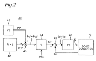
- FIG 2 is a flow diagram illustrating a control flow of the charge and discharge control unit 40 in the controller 10 of Figure 1 .
- the charge and discharge control unit 40 includes PI (proportional integral) controllers 41 and 46, a control function value output unit 42, an adder 43, a divider 44, and a subtractor 45.
- the PI controller 41 generates an output power instruction value Pc* (kW) for the capacitor 2 in accordance with the load 7 and outputs the output power instruction value Pc* to the adder 43.
- control function value output unit 42 calculates a function value Pet* (kW) of a temperature control function F ( ⁇ ) for the secondary battery 1, which will be described in detail below, and outputs the function value Pet* (kW) to the adder 43.
- the adder 43 adds up the two input values and outputs an added result, that is, an instruction value (Pc* + Pct*), to the divider 44.
- the divider 44 divides the input instruction value (Pc* + Pet*) by the voltage Vdc on the DC link 8 and outputs a divided result, that is, a primary-side current instruction value Ic* (A) for the capacitor 2, to the subtractor 45.
- the subtractor 45 subtracts a capacitor primary-side current value Ic (A) measured by the current detector 31 from the primary-side current instruction value Ic* for the capacitor 2 and outputs a subtracted result, that is, an error value (Ic* - Ic), to the PI controller 46.
- the PI controller 46 controls a duty factor D of the DC-DC converter 3 based on the error value (Ic* - Ic) so that the error value (Ic* - Ic) becomes 0.
- the primary-side current Ic of the capacitor 2 is a current on the reactor 4 and DC link 8 side and measured by the current detector 31.
- the charge and discharge control unit 40 of Figure 2 configured above is provided with: the PI controller 41 that uses the output power instruction value Pc* for the capacitor 2 depending on the load 7 as a controlled amount; and the PI controller 46 that uses the conduction ratio D of the DC-DC converter 3 depending on the primary-side current instruction value Ic* for the capacitor 2 as a controlled amount. Furthermore, the adder 43 adds an output power instruction value Pet* determined by the temperature control of the secondary battery 1 to the output power instruction value Pc* for the capacitor 2 depending on the load current Iac.
- the DC-DC converter 3 controls the primary-side current Ic of the capacitor 2 in accordance with the load current Iac on the AC side, indirectly controlling a current Ib of the secondary battery 1.
- the DC-DC converter 3 controls the voltage Vdc on the DC link 8 so as to become the same as the voltage Vb of the secondary battery 1.
- the temperature control function F ( ⁇ ) for the secondary battery 1 will be described below. Repeated charging and discharging between the secondary battery 1 and the capacitor 2 in order to increase the temperature is based on the temperature control function F ( ⁇ ).
- measurement values are as follows.
- the controller 10 estimates and calculates SOCs by using the voltage tables, but the present invention is not limited to this.
- the controller 10 may estimate and calculate the SOCs by using a current integrating method or other methods. Namely, the controller 10 can estimate and calculate the SOCs, based on a voltage of the secondary battery 1 or the capacitor 2 or a current thereof.
- a control rule of a temperature control process is as follows.
- a control rule of the secondary battery 1 is as follows.
- the controller 10 uses the following equation to determine a maximum discharging current Ib_discharge and a maximum charging current Ib_charge from the internal resistance Rb determined from the above (R1).
- V b_Min func 1 Soc b_Min ⁇ R b ⁇ I b_disch arg e
- V b_Max func 1 Soc b_Min + R b ⁇ I b_ch arg e
- the controller 10 uses the following equation to determine chargeable power Wb_charge (W) and dischargeable power Wb_discharge (W) from the voltage Vb (V) of the secondary battery 1, the number of cells interconnected in series Nb, and the number of cells interconnected in parallel Mb.
- W b_ch arg e V b ⁇ I b_ch arg e ⁇ N b ⁇ M b
- W b_disch arg e V b ⁇ I b_disch arg e ⁇ N b ⁇ M b
- a control rule of the capacitor 2 is as follows.
- the controller 10 uses the following equations to determine chargeable power Wc_charge (W) and dischargeable power Wc_discharge (W) from a capacitor voltage Vc (V), the number of cells interconnected in series Nc, and the number of cells interconnected in parallel Mc.
- W c_ch arg e V c ⁇ I c_ch arg e ⁇ N c ⁇ M c
- W c_disch arg e V c ⁇ I c_disch arg e ⁇ N c ⁇ M c
- control rules of the secondary battery 1 and the capacitor 2 are as follows.
- the control function value output unit 42 When determining the output power instruction value Pet* in the above manner, the control function value output unit 42 outputs the output power instruction value Pet* as a temperature control function value. Based on this, the charge and discharge control unit 40 of Figure 2 calculates a conduction ratio D and sets this conduction ratio D to the DC-DC converter 3, controlling a temperature Tb of the secondary battery 1.
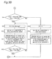
- Figures 3A and 3B are flowcharts each representing a process of controlling a temperature of the electricity storage device, the process being performed by the controller 10 of Figure 1 .
- step S1 of Figure 3A the controller 10 calculates a Socb of the secondary battery 1 with reference to a voltage table based on a voltage of the secondary battery 1.
- step S2 the controller 10 calculates a Socc of the capacitor 2 with reference to a voltage table based on a voltage of the capacitor 2.
- step S3 the controller 10 determines whether or not Socb > Socb_Min and Socc ⁇ Socc_Max. If the determination result is NO, the process proceeds to step S4 of Figure 3B . If the determination result is YES, the process proceeds to step S5.
- step S5 the controller 10 sets the capacitor charge instruction value Pct_charge* calculated using Equation 10 as the output power instruction value Pct*.
- step S6 the controller 10 sets the DC-DC converter 3 into the charging mode from the capacitor 2 to the secondary battery 1.
- step S7 the controller 10 causes the charge and discharge control unit 40 to perform the process of Figure 2 , calculating a duty factor D of the DC-DC converter 3. Based on this, the controller 10 controls the duty ratio, controlling a switching operation. Then, the process proceeds to step S8.
- step S8 the controller 10 determines whether Socb ⁇ Socb_Min or Socc > Socc_Max. If the determination result is NO, the process returns to step S5, and the DC-DC converter 3 continues to be in the charging mode. If the determination result is YES, the process returns to step S1.
- step S4 of Figure 3B the controller 10 determines whether or not Socb ⁇ Socb_Max and Socc > Socc_Min. If the determination result is NO, the process proceeds to step S 13. If the determination result is YES, the process proceeds to step S9. In step S9, the controller 10 sets the capacitor discharge instruction value Pct_discharge* calculated using Equation 11 as the output power instruction value Pct*. In step S10, the controller 10 sets the DC-DC converter 3 into the discharging mode from the secondary battery 1 to the capacitor 2. In step S11, the controller 10 causes the charge and discharge control unit 40 to perform the process of Figure 2 , calculating a duty factor D of the DC-DC converter 3. Based on this, the controller 10 controls the duty ratio, controlling the switching operation.
- step S12 the controller 10 determines whether Socb > Socb_Max or Socc ⁇ Socc_Min. If the determination result is NO, the process returns to step S9, and the DC-DC converter 3 continues to be in the discharging mode. If the determination result is YES, the process returns to step S1.
- step S13 the controller 10 sets the output power instruction value Pet* to 0.
- step S14 the controller 10 sets the DC-DC converter 3 into a stop mode.
- step S15 the controller 10 sets the duty factor D of the DC-DC converter 3 to 0, and stops the DC-DC converter 3. After the processing in step S15, the process returns to step S 1.
- Figure 4 is a graph of a capacitor SOC (Socc) in relation to a secondary battery SOC (Socb), illustrating regions of the charging mode, the discharging mode, and the stop mode, in the processes of controlling a temperature of the electricity storage device of Figures 3A and 3B .
- Socc capacitor SOC
- Socb secondary battery SOC
- the two-dimensional plane of Figure 4 is separated into four states (charging mode, discharging mode, stop mode, and either one of charging and discharging) by four SOC parameters (Socc_Max, Socc_Min, Socb_Max, and Socb_Min).
- the inventors of the present invention simulated a case of increasing a battery temperature Tb from 22 °C to 23 °C by using the electricity storage system of Figure 1 .
- Figures 5A to 5D and Figures 6A to 6D illustrate the results thereof.
- the conditions of this simulation were set as follows.
- Figures 5A to 5D illustrate simulation results of the electricity storage system of Figure 1 .
- Figure 5A is a waveform chart illustrating output power of each of a lithium ion battery (LiB) and a lithium ion capacitor (LiC) with elapsed time.
- Figure 5B is a waveform chart illustrating a voltage of each of the lithium ion battery (LiB) and the lithium ion capacitor (LiC) and a DC link voltage Vdc with elapsed time.
- Figure 5C is a waveform chart illustrating a current of each of the lithium ion battery (LiB) and the lithium ion capacitor (LiC) with elapsed time.
- Figure 5D is a waveform chart illustrating a cell voltage of each of the lithium ion battery (LiB) and the lithium ion capacitor (LiC) with elapsed time.
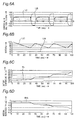
- Figure 6A to Figure 6D illustrate simulation results of the electricity storage system of Figure 1 .
- Figure 6A is a waveform chart illustrating a current upon one parallel row in each of the lithium ion battery (LiB) and the lithium ion capacitor (LiC) with elapsed time.
- Figure 6B is a waveform chart illustrating a SOC of each of the lithium ion battery (LiB) and the lithium ion capacitor (LiC) with elapsed time.
- Figure 6C is a waveform chart illustrating a battery temperature Tb of the lithium ion battery (LiB) with elapsed time.
- Figure 6D is a waveform chart illustrating an internal resistance Rrb of the lithium ion battery (LiB) with elapsed time.
- this implementation example enables the battery temperature to increase by 1°C in about 100 seconds. As can be understood from the above, it is possible to increase the temperature to a preset temperature at a maximum possible rate.
- an electricity storage system using a secondary battery 1 and a capacitor 2 in combination is constituted.
- This electricity storage system easily increases a temperature of the secondary battery 1 to a preset temperature at a maximum possible rate by controlling charging and discharging between the secondary battery 1 and the capacitor 2.
- electricity consumed during the increase in the temperature can be reduced to only charging and discharging efficiencies of the secondary battery and the capacitor.
- the secondary battery 1, such as a lithium ion battery is used as a first electricity storage device, but the present invention is not limited to this.
- a lead-acid battery, a nickel-cadmium battery, a nickel-hydrogen battery, and a lithium ion polymer battery may be used.
- a lithium ion capacitor is used as a second electricity storage device, but the present invention is not limited to this.
- an electric double-layer capacitor may be used.
- the electricity storage system including two electricity storage devices that is, the secondary battery 1 and the capacitor 2 has been described, but the present invention is not limited to this.
- An electricity storage system including three or more electricity storage devices may be constituted, and charging and discharging may be performed between the individual electricity storage devices.
- the AC load 7 is applicable to, for example, AC electrical equipment in an electric propulsion system for an AC motor in a vehicle, a vessel, or the like.
Landscapes
- Engineering & Computer Science (AREA)
- Power Engineering (AREA)
- Mechanical Engineering (AREA)
- Transportation (AREA)
- Chemical Kinetics & Catalysis (AREA)
- Electrochemistry (AREA)
- General Chemical & Material Sciences (AREA)
- Chemical & Material Sciences (AREA)
- Manufacturing & Machinery (AREA)
- Life Sciences & Earth Sciences (AREA)
- Sustainable Development (AREA)
- Sustainable Energy (AREA)
- Automation & Control Theory (AREA)
- Secondary Cells (AREA)
- Electric Propulsion And Braking For Vehicles (AREA)
- Charge And Discharge Circuits For Batteries Or The Like (AREA)
Applications Claiming Priority (2)
| Application Number | Priority Date | Filing Date | Title |
|---|---|---|---|
| JP2013269206A JP2015125880A (ja) | 2013-12-26 | 2013-12-26 | 蓄電デバイスの温度制御装置及び方法、並びに電力貯蔵システム |
| PCT/JP2014/084559 WO2015099138A1 (fr) | 2013-12-26 | 2014-12-26 | Appareil de régulation de température pour dispositif de stockage d'énergie électrique |
Publications (2)
| Publication Number | Publication Date |
|---|---|
| EP3089256A1 true EP3089256A1 (fr) | 2016-11-02 |
| EP3089256A4 EP3089256A4 (fr) | 2017-08-16 |
Family
ID=53478977
Family Applications (1)
| Application Number | Title | Priority Date | Filing Date |
|---|---|---|---|
| EP14873252.2A Withdrawn EP3089256A4 (fr) | 2013-12-26 | 2014-12-26 | Appareil de régulation de température pour dispositif de stockage d'énergie électrique |
Country Status (5)
| Country | Link |
|---|---|
| US (1) | US9975447B2 (fr) |
| EP (1) | EP3089256A4 (fr) |
| JP (1) | JP2015125880A (fr) |
| CA (1) | CA2935019A1 (fr) |
| WO (1) | WO2015099138A1 (fr) |
Cited By (3)
| Publication number | Priority date | Publication date | Assignee | Title |
|---|---|---|---|---|
| EP3447872A1 (fr) * | 2017-08-21 | 2019-02-27 | Fuji Electric Co., Ltd. | Système de réduction de fluctuation de puissance |
| EP3490053A1 (fr) * | 2017-11-28 | 2019-05-29 | Ningbo Geely Automobile Research & Development Co. Ltd. | Chauffage interne d'une batterie |
| CN111231677A (zh) * | 2020-01-22 | 2020-06-05 | 东风汽车集团有限公司 | 一种用于纯电动车能量流的测试方法及系统 |
Families Citing this family (32)
| Publication number | Priority date | Publication date | Assignee | Title |
|---|---|---|---|---|
| US9929449B2 (en) * | 2014-06-10 | 2018-03-27 | Vertiv Energy Systems, Inc. | Systems and methods for warming batteries |
| US9809119B2 (en) * | 2015-01-13 | 2017-11-07 | General Electric Company | Bi-directional DC-DC power converter for a vehicle system |
| JP6527785B2 (ja) * | 2015-08-19 | 2019-06-05 | 本田技研工業株式会社 | 駆動装置及び輸送機器 |
| JP6531010B2 (ja) * | 2015-08-19 | 2019-06-12 | 本田技研工業株式会社 | 駆動装置、輸送機器及び蓄電器制御方法 |
| JP2017041974A (ja) * | 2015-08-19 | 2017-02-23 | 本田技研工業株式会社 | 駆動装置及びその制御方法、並びに、輸送機器 |
| JP2017085754A (ja) | 2015-10-27 | 2017-05-18 | 本田技研工業株式会社 | 蓄電装置、輸送機器及び制御方法 |
| DE102016205333A1 (de) * | 2016-03-31 | 2017-10-05 | Siemens Aktiengesellschaft | Verfahren und Vorrichtung zum Temperieren eines Akkumulators |
| DE102017002483A1 (de) * | 2017-03-15 | 2018-09-20 | Man Truck & Bus Ag | Technik zur Isolationsüberwachung in Fahrzeugen |
| US10875397B2 (en) * | 2017-06-30 | 2020-12-29 | Hamilton Sundstrand Corporation | HESM fast recharge algorithm |
| DE102018102211B3 (de) * | 2018-02-01 | 2019-09-19 | Dr. Ing. H.C. F. Porsche Aktiengesellschaft | Batteriesystem für ein batteriebetriebenes elektrisches Fahrzeug und Verfahren zum Nutzen einer Restreichweite eines solchen |
| WO2020049943A1 (fr) * | 2018-09-05 | 2020-03-12 | 住友電気工業株式会社 | Dispositif d'augmentation de température de batterie rechargeable, programme informatique et procédé d'augmentation de température de batterie rechargeable |
| CN109786868B (zh) * | 2018-12-13 | 2020-11-06 | 北京理工大学 | 一种电动船舶电池系统热失控的处理方法、系统及装置 |
| KR102731551B1 (ko) * | 2019-03-04 | 2024-11-18 | 현대자동차주식회사 | 배터리 충방전 제어 시스템 및 방법 |
| CN109950660B (zh) * | 2019-03-25 | 2022-01-18 | 清华大学 | 三元锂离子动力电池利用自身储能激励预热的方法 |
| CN109904540B (zh) * | 2019-03-25 | 2022-03-04 | 哈尔滨理工大学 | 一种用于磷酸铁锂动力电池的低温交变激励预热方法 |
| CN109950661B (zh) * | 2019-03-25 | 2022-04-12 | 清华大学 | 一种动力电池组的内外部同时加热的装置及方法 |
| EP3859870A4 (fr) * | 2019-10-21 | 2022-06-15 | Ningde Amperex Technology Ltd. | Procédé de charge, dispositif électronique et support de stockage |
| CN110828918B (zh) * | 2019-11-13 | 2023-03-24 | 奇瑞新能源汽车股份有限公司 | 一种汽车动力电池的控制系统及控制方法 |
| CN110920393B (zh) * | 2019-11-27 | 2021-07-23 | 浙江合众新能源汽车有限公司 | 一种电动汽车低压电源系统及其低压锂电池充放电方法 |
| US11967855B2 (en) | 2019-12-31 | 2024-04-23 | Ways Technical Corp., Ltd | Capacitor device used in energy storage system |
| US11901762B2 (en) | 2019-12-31 | 2024-02-13 | Ways Technical Corp., Ltd. | Energy storage system |
| TWI780392B (zh) * | 2019-12-31 | 2022-10-11 | 位速科技股份有限公司 | 能量儲存系統 |
| CN113162205B (zh) * | 2020-01-07 | 2024-12-13 | 位速科技股份有限公司 | 能量存储系统 |
| CN113733986A (zh) * | 2020-05-29 | 2021-12-03 | 比亚迪股份有限公司 | 电池自加热装置及其控制方法和车辆 |
| CN112134342B (zh) * | 2020-08-07 | 2022-12-06 | 华为数字能源技术有限公司 | 一种储能装置、系统以及储能装置的控制方法 |
| CN112366769B (zh) * | 2020-10-30 | 2023-07-04 | 武汉格罗夫氢能汽车有限公司 | 一种吹扫阶段NiH电池充电控制系统及方法 |
| JP7522138B2 (ja) | 2021-08-05 | 2024-07-24 | 寧徳時代新能源科技股▲分▼有限公司 | 動力電池加熱システム、その制御方法及び制御回路 |
| CN115956332B (zh) * | 2021-11-22 | 2025-08-05 | 宁德时代新能源科技股份有限公司 | 充放电电路、系统及其控制方法 |
| CN114400388A (zh) * | 2022-01-20 | 2022-04-26 | 阳光电源股份有限公司 | 一种储能系统及其电池加热方法 |
| CN115139829B (zh) * | 2022-07-29 | 2024-06-18 | 潍柴动力股份有限公司 | 一种充电加热控制方法、装置、电子设备及存储介质 |
| DE102023203761A1 (de) * | 2023-04-24 | 2024-10-24 | Volkswagen Aktiengesellschaft | Anordnung in einem Fahrzeug und Verfahren zum Betreiben eines Fahrzeugs |
| US12512692B1 (en) * | 2024-11-25 | 2025-12-30 | Shenzhen Leagend Optoelectronics Co., Ltd. | Supercapacitor control circuit and method for intelligently identifying starting mode of vehicle |
Family Cites Families (14)
| Publication number | Priority date | Publication date | Assignee | Title |
|---|---|---|---|---|
| US6075328A (en) * | 1996-10-18 | 2000-06-13 | Hitachi, Ltd. | PWM/PAM control mode switching type motor control apparatus, and motor drive and air-conditioner using the same |
| JP3379444B2 (ja) | 1998-09-07 | 2003-02-24 | トヨタ自動車株式会社 | ハイブリッド車の充放電状態制御装置 |
| JP5050324B2 (ja) * | 2005-07-04 | 2012-10-17 | トヨタ自動車株式会社 | 二次電池の制御装置 |
| JP2008017559A (ja) * | 2006-07-03 | 2008-01-24 | Toyota Motor Corp | 電圧変換装置およびそれを備えた車両 |
| JP4379441B2 (ja) * | 2006-07-18 | 2009-12-09 | トヨタ自動車株式会社 | 電源システムおよびそれを備えた車両、蓄電装置の昇温制御方法、ならびに蓄電装置の昇温制御をコンピュータに実行させるためのプログラムを記録したコンピュータ読取可能な記録媒体 |
| JP2008061487A (ja) * | 2006-07-31 | 2008-03-13 | Toyota Motor Corp | 電源システムおよびそれを備えた車両、蓄電装置の昇温制御方法、ならびに蓄電装置の昇温制御をコンピュータに実行させるためのプログラムを記録したコンピュータ読取可能な記録媒体 |
| JP5011940B2 (ja) * | 2006-10-16 | 2012-08-29 | トヨタ自動車株式会社 | 電源装置、および車両 |
| JP4656042B2 (ja) * | 2006-10-24 | 2011-03-23 | トヨタ自動車株式会社 | 電源システムおよびそれを備えた車両、電源システムの制御方法、ならびに電源システムの制御方法をコンピュータに実行させるためのプログラムを記録したコンピュータ読取可能な記録媒体 |
| JP4600390B2 (ja) * | 2006-12-14 | 2010-12-15 | トヨタ自動車株式会社 | 電源システムおよびそれを備える車両、ならびにその制御方法 |
| JP4930482B2 (ja) * | 2008-09-30 | 2012-05-16 | 株式会社デンソー | バッテリの充放電制御装置 |
| US8575897B2 (en) * | 2008-10-03 | 2013-11-05 | Denso Corporation | Battery temperature control system |
| JP5288170B2 (ja) * | 2008-10-03 | 2013-09-11 | 株式会社デンソー | バッテリの昇温制御装置 |
| JP5567040B2 (ja) | 2012-01-19 | 2014-08-06 | 株式会社東芝 | 二次電池の制御装置 |
| WO2013114522A1 (fr) * | 2012-01-30 | 2013-08-08 | トヨタ自動車株式会社 | Dispositif de réception d'énergie de véhicule, équipement d'alimentation en énergie et système de transmission d'énergie électrique |
-
2013
- 2013-12-26 JP JP2013269206A patent/JP2015125880A/ja active Pending
-
2014
- 2014-12-26 US US15/108,181 patent/US9975447B2/en active Active
- 2014-12-26 EP EP14873252.2A patent/EP3089256A4/fr not_active Withdrawn
- 2014-12-26 CA CA2935019A patent/CA2935019A1/fr not_active Abandoned
- 2014-12-26 WO PCT/JP2014/084559 patent/WO2015099138A1/fr not_active Ceased
Cited By (4)
| Publication number | Priority date | Publication date | Assignee | Title |
|---|---|---|---|---|
| EP3447872A1 (fr) * | 2017-08-21 | 2019-02-27 | Fuji Electric Co., Ltd. | Système de réduction de fluctuation de puissance |
| EP3490053A1 (fr) * | 2017-11-28 | 2019-05-29 | Ningbo Geely Automobile Research & Development Co. Ltd. | Chauffage interne d'une batterie |
| CN111231677A (zh) * | 2020-01-22 | 2020-06-05 | 东风汽车集团有限公司 | 一种用于纯电动车能量流的测试方法及系统 |
| CN111231677B (zh) * | 2020-01-22 | 2021-07-06 | 东风汽车集团有限公司 | 一种用于纯电动车能量流的测试方法及系统 |
Also Published As
| Publication number | Publication date |
|---|---|
| WO2015099138A1 (fr) | 2015-07-02 |
| CA2935019A1 (fr) | 2015-07-02 |
| EP3089256A4 (fr) | 2017-08-16 |
| US9975447B2 (en) | 2018-05-22 |
| US20160318418A1 (en) | 2016-11-03 |
| JP2015125880A (ja) | 2015-07-06 |
Similar Documents
| Publication | Publication Date | Title |
|---|---|---|
| US9975447B2 (en) | Temperature control apparatus for electricity storage device for use in electricity storage system including electricity storage devices | |
| US10059222B2 (en) | Battery temperature estimation system | |
| CN103192729B (zh) | 电动车辆 | |
| JP5381026B2 (ja) | 複合電源装置の制御回路 | |
| KR101052847B1 (ko) | 컨버터제어장치 | |
| US20170203654A1 (en) | Closed loop feedback control to mitigate lithium plating in electrified vehicle battery | |
| US20160093927A1 (en) | Battery capacity degradation resolution methods and systems | |
| JP3882703B2 (ja) | 蓄電システム | |
| Kieldsen et al. | Efficiency test method for electric vehicle chargers | |
| EP3157132A1 (fr) | Système de stockage d'énergie électrique et son procédé de commande | |
| EP4077021A1 (fr) | Procédé de prédiction d'une charge électrique imprimée sur chaque unité de batterie dans un système de stockage d'énergie électrique | |
| Oubelaid et al. | Novel coordinated power sources switching strategy for transient performance enhancement of hybrid electric vehicles | |
| JP6348219B2 (ja) | Dc−dc電圧コンバータの入力電力の限度を調節するための電力制御システム及び方法 | |
| JP6668910B2 (ja) | バッテリ容量測定装置及びバッテリ容量測定プログラム | |
| JP2014202630A (ja) | 電池システム | |
| Barote et al. | A new control method for VRB SOC estimation in stand-alone wind energy systems | |
| US20160043581A1 (en) | Controller for battery system | |
| CN102934314A (zh) | 电池包 | |
| US10525835B2 (en) | Power control apparatus and power control system | |
| KR20190071459A (ko) | 배터리 충전 시스템 및 이를 이용한 배터리 모듈의 최대용량 충전 제어방법 | |
| Hasaranga et al. | A Fuzzy logic based battery SOC level control strategy for smart Micro grid | |
| US20140095088A1 (en) | Systems and methods for characterization of energy storage devices | |
| Zahedi et al. | Globally Optimal Energy Management in a Battery-Ultracapacitor Electric Vehicle | |
| JP2017192272A (ja) | 電源制御装置 | |
| Kim et al. | Adaptive loss reduction charging strategy considering variation of internal impedance of lithium-ion polymer batteries in electric vehicle charging systems |
Legal Events
| Date | Code | Title | Description |
|---|---|---|---|
| PUAI | Public reference made under article 153(3) epc to a published international application that has entered the european phase |
Free format text: ORIGINAL CODE: 0009012 |
|
| 17P | Request for examination filed |
Effective date: 20160623 |
|
| AK | Designated contracting states |
Kind code of ref document: A1 Designated state(s): AL AT BE BG CH CY CZ DE DK EE ES FI FR GB GR HR HU IE IS IT LI LT LU LV MC MK MT NL NO PL PT RO RS SE SI SK SM TR |
|
| AX | Request for extension of the european patent |
Extension state: BA ME |
|
| DAX | Request for extension of the european patent (deleted) | ||
| A4 | Supplementary search report drawn up and despatched |
Effective date: 20170714 |
|
| RIC1 | Information provided on ipc code assigned before grant |
Ipc: H01M 10/625 20140101ALI20170710BHEP Ipc: H01M 10/44 20060101ALI20170710BHEP Ipc: H02J 7/00 20060101ALI20170710BHEP Ipc: B60L 1/00 20060101ALI20170710BHEP Ipc: B60L 11/18 20060101ALI20170710BHEP Ipc: B60L 3/12 20060101ALI20170710BHEP Ipc: H01M 10/615 20140101ALI20170710BHEP Ipc: H01M 10/0525 20100101ALI20170710BHEP Ipc: H01M 10/637 20140101ALI20170710BHEP Ipc: H01M 10/633 20140101AFI20170710BHEP Ipc: B60L 11/00 20060101ALI20170710BHEP Ipc: H01M 10/48 20060101ALI20170710BHEP |
|
| STAA | Information on the status of an ep patent application or granted ep patent |
Free format text: STATUS: REQUEST FOR EXAMINATION WAS MADE |
|
| STAA | Information on the status of an ep patent application or granted ep patent |
Free format text: STATUS: THE APPLICATION IS DEEMED TO BE WITHDRAWN |
|
| 18D | Application deemed to be withdrawn |
Effective date: 20180213 |