EP3089355A1 - Module cellule photovoltaïque à double verre - Google Patents
Module cellule photovoltaïque à double verre Download PDFInfo
- Publication number
- EP3089355A1 EP3089355A1 EP14875670.3A EP14875670A EP3089355A1 EP 3089355 A1 EP3089355 A1 EP 3089355A1 EP 14875670 A EP14875670 A EP 14875670A EP 3089355 A1 EP3089355 A1 EP 3089355A1
- Authority
- EP
- European Patent Office
- Prior art keywords
- glass
- layer
- double
- cell module
- photovoltaic cell
- Prior art date
- Legal status (The legal status is an assumption and is not a legal conclusion. Google has not performed a legal analysis and makes no representation as to the accuracy of the status listed.)
- Withdrawn
Links
- 239000011521 glass Substances 0.000 title claims abstract description 156
- 238000005538 encapsulation Methods 0.000 claims abstract description 62
- 238000000576 coating method Methods 0.000 claims abstract description 25
- 239000011248 coating agent Substances 0.000 claims abstract description 24
- 238000007789 sealing Methods 0.000 claims abstract description 13
- VYPSYNLAJGMNEJ-UHFFFAOYSA-N Silicium dioxide Chemical compound O=[Si]=O VYPSYNLAJGMNEJ-UHFFFAOYSA-N 0.000 claims description 11
- 239000000741 silica gel Substances 0.000 claims description 11
- 229910002027 silica gel Inorganic materials 0.000 claims description 11
- 229960001866 silicon dioxide Drugs 0.000 claims description 11
- 229920005549 butyl rubber Polymers 0.000 claims description 6
- 229920000098 polyolefin Polymers 0.000 claims description 6
- 238000005452 bending Methods 0.000 claims description 5
- 239000012212 insulator Substances 0.000 claims description 5
- 239000002390 adhesive tape Substances 0.000 claims description 4
- AZDRQVAHHNSJOQ-UHFFFAOYSA-N alumane Chemical group [AlH3] AZDRQVAHHNSJOQ-UHFFFAOYSA-N 0.000 claims description 4
- 238000010030 laminating Methods 0.000 claims description 4
- 239000000565 sealant Substances 0.000 claims description 3
- 229920002367 Polyisobutene Polymers 0.000 claims description 2
- 229920001971 elastomer Polymers 0.000 claims description 2
- 239000005338 frosted glass Substances 0.000 claims description 2
- 229920002521 macromolecule Polymers 0.000 claims description 2
- 238000009434 installation Methods 0.000 description 9
- XLYOFNOQVPJJNP-UHFFFAOYSA-N water Chemical compound O XLYOFNOQVPJJNP-UHFFFAOYSA-N 0.000 description 9
- 239000000463 material Substances 0.000 description 8
- 239000005341 toughened glass Substances 0.000 description 7
- QTBSBXVTEAMEQO-UHFFFAOYSA-N Acetic acid Chemical compound CC(O)=O QTBSBXVTEAMEQO-UHFFFAOYSA-N 0.000 description 6
- XEEYBQQBJWHFJM-UHFFFAOYSA-N Iron Chemical compound [Fe] XEEYBQQBJWHFJM-UHFFFAOYSA-N 0.000 description 6
- 239000003292 glue Substances 0.000 description 6
- 238000005192 partition Methods 0.000 description 6
- 229920000642 polymer Polymers 0.000 description 6
- 230000000694 effects Effects 0.000 description 5
- 230000008901 benefit Effects 0.000 description 4
- 230000002349 favourable effect Effects 0.000 description 4
- -1 polyethylene Polymers 0.000 description 4
- 238000004382 potting Methods 0.000 description 4
- 230000002035 prolonged effect Effects 0.000 description 4
- 238000002835 absorbance Methods 0.000 description 3
- 230000032683 aging Effects 0.000 description 3
- 239000004020 conductor Substances 0.000 description 3
- 229910052742 iron Inorganic materials 0.000 description 3
- 238000003475 lamination Methods 0.000 description 3
- 238000000034 method Methods 0.000 description 3
- 230000008569 process Effects 0.000 description 3
- 229920001187 thermosetting polymer Polymers 0.000 description 3
- ROLAGNYPWIVYTG-UHFFFAOYSA-N 1,2-bis(4-methoxyphenyl)ethanamine;hydrochloride Chemical compound Cl.C1=CC(OC)=CC=C1CC(N)C1=CC=C(OC)C=C1 ROLAGNYPWIVYTG-UHFFFAOYSA-N 0.000 description 2
- 239000002033 PVDF binder Substances 0.000 description 2
- 239000004698 Polyethylene Substances 0.000 description 2
- 239000002313 adhesive film Substances 0.000 description 2
- NBVXSUQYWXRMNV-UHFFFAOYSA-N fluoromethane Chemical compound FC NBVXSUQYWXRMNV-UHFFFAOYSA-N 0.000 description 2
- 239000007788 liquid Substances 0.000 description 2
- 239000004033 plastic Substances 0.000 description 2
- 229920003023 plastic Polymers 0.000 description 2
- 229920000573 polyethylene Polymers 0.000 description 2
- 239000002861 polymer material Substances 0.000 description 2
- 229920001343 polytetrafluoroethylene Polymers 0.000 description 2
- 239000004810 polytetrafluoroethylene Substances 0.000 description 2
- 229920002981 polyvinylidene fluoride Polymers 0.000 description 2
- 239000011347 resin Substances 0.000 description 2
- 229920005989 resin Polymers 0.000 description 2
- 229920001169 thermoplastic Polymers 0.000 description 2
- 239000004416 thermosoftening plastic Substances 0.000 description 2
- 241001673391 Entandrophragma candollei Species 0.000 description 1
- ATJFFYVFTNAWJD-UHFFFAOYSA-N Tin Chemical compound [Sn] ATJFFYVFTNAWJD-UHFFFAOYSA-N 0.000 description 1
- 238000005299 abrasion Methods 0.000 description 1
- 238000010521 absorption reaction Methods 0.000 description 1
- 230000009471 action Effects 0.000 description 1
- 238000004026 adhesive bonding Methods 0.000 description 1
- 238000003491 array Methods 0.000 description 1
- 230000005540 biological transmission Effects 0.000 description 1
- 238000006243 chemical reaction Methods 0.000 description 1
- 238000004891 communication Methods 0.000 description 1
- 230000007547 defect Effects 0.000 description 1
- 238000010586 diagram Methods 0.000 description 1
- 230000002708 enhancing effect Effects 0.000 description 1
- 238000011900 installation process Methods 0.000 description 1
- 238000009413 insulation Methods 0.000 description 1
- 238000012423 maintenance Methods 0.000 description 1
- 239000011159 matrix material Substances 0.000 description 1
- 238000012986 modification Methods 0.000 description 1
- 230000004048 modification Effects 0.000 description 1
- 229910052573 porcelain Inorganic materials 0.000 description 1
- 238000007639 printing Methods 0.000 description 1
- 238000012545 processing Methods 0.000 description 1
- 238000002310 reflectometry Methods 0.000 description 1
- 230000011218 segmentation Effects 0.000 description 1
- 150000003384 small molecules Chemical class 0.000 description 1
- 229910000679 solder Inorganic materials 0.000 description 1
- 239000007787 solid Substances 0.000 description 1
- 238000005507 spraying Methods 0.000 description 1
- 230000035882 stress Effects 0.000 description 1
- 229920002397 thermoplastic olefin Polymers 0.000 description 1
- 238000002834 transmittance Methods 0.000 description 1
- 239000006097 ultraviolet radiation absorber Substances 0.000 description 1
- 238000003466 welding Methods 0.000 description 1
Images


Classifications
-
- H—ELECTRICITY
- H10—SEMICONDUCTOR DEVICES; ELECTRIC SOLID-STATE DEVICES NOT OTHERWISE PROVIDED FOR
- H10F—INORGANIC SEMICONDUCTOR DEVICES SENSITIVE TO INFRARED RADIATION, LIGHT, ELECTROMAGNETIC RADIATION OF SHORTER WAVELENGTH OR CORPUSCULAR RADIATION
- H10F19/00—Integrated devices, or assemblies of multiple devices, comprising at least one photovoltaic cell covered by group H10F10/00, e.g. photovoltaic modules
- H10F19/80—Encapsulations or containers for integrated devices, or assemblies of multiple devices, having photovoltaic cells
- H10F19/807—Double-glass encapsulation, e.g. photovoltaic cells arranged between front and rear glass sheets
-
- H—ELECTRICITY
- H02—GENERATION; CONVERSION OR DISTRIBUTION OF ELECTRIC POWER
- H02S—GENERATION OF ELECTRIC POWER BY CONVERSION OF INFRARED RADIATION, VISIBLE LIGHT OR ULTRAVIOLET LIGHT, e.g. USING PHOTOVOLTAIC [PV] MODULES
- H02S30/00—Structural details of PV modules other than those related to light conversion
- H02S30/10—Frame structures
-
- H—ELECTRICITY
- H02—GENERATION; CONVERSION OR DISTRIBUTION OF ELECTRIC POWER
- H02S—GENERATION OF ELECTRIC POWER BY CONVERSION OF INFRARED RADIATION, VISIBLE LIGHT OR ULTRAVIOLET LIGHT, e.g. USING PHOTOVOLTAIC [PV] MODULES
- H02S40/00—Components or accessories in combination with PV modules, not provided for in groups H02S10/00 - H02S30/00
- H02S40/30—Electrical components
- H02S40/34—Electrical components comprising specially adapted electrical connection means to be structurally associated with the PV module, e.g. junction boxes
-
- H—ELECTRICITY
- H10—SEMICONDUCTOR DEVICES; ELECTRIC SOLID-STATE DEVICES NOT OTHERWISE PROVIDED FOR
- H10F—INORGANIC SEMICONDUCTOR DEVICES SENSITIVE TO INFRARED RADIATION, LIGHT, ELECTROMAGNETIC RADIATION OF SHORTER WAVELENGTH OR CORPUSCULAR RADIATION
- H10F19/00—Integrated devices, or assemblies of multiple devices, comprising at least one photovoltaic cell covered by group H10F10/00, e.g. photovoltaic modules
-
- H—ELECTRICITY
- H10—SEMICONDUCTOR DEVICES; ELECTRIC SOLID-STATE DEVICES NOT OTHERWISE PROVIDED FOR
- H10F—INORGANIC SEMICONDUCTOR DEVICES SENSITIVE TO INFRARED RADIATION, LIGHT, ELECTROMAGNETIC RADIATION OF SHORTER WAVELENGTH OR CORPUSCULAR RADIATION
- H10F77/00—Constructional details of devices covered by this subclass
- H10F77/30—Coatings
- H10F77/306—Coatings for devices having potential barriers
- H10F77/311—Coatings for devices having potential barriers for photovoltaic cells
- H10F77/315—Coatings for devices having potential barriers for photovoltaic cells the coatings being antireflective or having enhancing optical properties
-
- H—ELECTRICITY
- H10—SEMICONDUCTOR DEVICES; ELECTRIC SOLID-STATE DEVICES NOT OTHERWISE PROVIDED FOR
- H10F—INORGANIC SEMICONDUCTOR DEVICES SENSITIVE TO INFRARED RADIATION, LIGHT, ELECTROMAGNETIC RADIATION OF SHORTER WAVELENGTH OR CORPUSCULAR RADIATION
- H10F77/00—Constructional details of devices covered by this subclass
- H10F77/40—Optical elements or arrangements
- H10F77/42—Optical elements or arrangements directly associated or integrated with photovoltaic cells, e.g. light-reflecting means or light-concentrating means
- H10F77/484—Refractive light-concentrating means, e.g. lenses
-
- H—ELECTRICITY
- H10—SEMICONDUCTOR DEVICES; ELECTRIC SOLID-STATE DEVICES NOT OTHERWISE PROVIDED FOR
- H10F—INORGANIC SEMICONDUCTOR DEVICES SENSITIVE TO INFRARED RADIATION, LIGHT, ELECTROMAGNETIC RADIATION OF SHORTER WAVELENGTH OR CORPUSCULAR RADIATION
- H10F77/00—Constructional details of devices covered by this subclass
- H10F77/93—Interconnections
- H10F77/933—Interconnections for devices having potential barriers
- H10F77/935—Interconnections for devices having potential barriers for photovoltaic devices or modules
- H10F77/937—Busbar structures for modules
-
- Y—GENERAL TAGGING OF NEW TECHNOLOGICAL DEVELOPMENTS; GENERAL TAGGING OF CROSS-SECTIONAL TECHNOLOGIES SPANNING OVER SEVERAL SECTIONS OF THE IPC; TECHNICAL SUBJECTS COVERED BY FORMER USPC CROSS-REFERENCE ART COLLECTIONS [XRACs] AND DIGESTS
- Y02—TECHNOLOGIES OR APPLICATIONS FOR MITIGATION OR ADAPTATION AGAINST CLIMATE CHANGE
- Y02E—REDUCTION OF GREENHOUSE GAS [GHG] EMISSIONS, RELATED TO ENERGY GENERATION, TRANSMISSION OR DISTRIBUTION
- Y02E10/00—Energy generation through renewable energy sources
- Y02E10/50—Photovoltaic [PV] energy
- Y02E10/52—PV systems with concentrators
Definitions
- the present disclosure relates to the field of solar cells and, in particular, to a double-glass photovoltaic cell module.
- An existing double-glass module uses tempered glass as a backplane, where a front surface uses EVA or PVB with a high UV transmittance, and a back surface uses a white EVA or PVB layer.
- the above double-glass module has following defects.
- the back of the double-glass module uses airtight and waterproof glass, which can prevent water vapor from entering the module.
- a gap between edges of two pieces of glass is still a weak point, and water vapor can still enters the module by passing through an encapsulation film.
- an airtight effect of glass it is difficult for the water vapor to spread out.
- an EVA encapsulation film is degraded to produce a small acetic acid molecule, which can still erode a cell, and reduce a service life of the module. If the module is PVB encapsulated, because PVB has high water absorption, the problem is more severe.
- a problem is that the white part may spread to the front surface of the cell after a long time of use and, thus, may block the cell, and cause a hot spot, affecting module efficiency.
- a disclosed solar photovoltaic module includes: a glass layer, a front layer adhesive film, a plurality of cells that are disposed in arrays at intervals, a back layer adhesive film, and a photovoltaic backplane.
- the photovoltaic backplane includes a specular reflection part covered by a cell and a diffused reflection part located at a gap between cells, where a cross section disclosing the diffused reflection part is an isosceles trapezoid or the diffused reflection part is a spherical diffused reflection part.
- a reflection layer is in a structure of an isosceles trapezoid, when an upper bottom surface is directly exposed in sunlight, the light is directly reflected off, and the light cannot be utilized, affecting photoelectric conversion efficiency.
- the reflection layer is in a structure of a trapezoid, during a lamination process, edges and corners of the trapezoid inevitably cause some damage to an encapsulation film and a cell edge, thereby reducing a service life of the entire solar cell module.
- An objective of the present disclosure is to resolve at least one of the technical problems in the prior art. Therefore, an objective of the present disclosure is to provide a double-glass photovoltaic cell module, and the double-glass photovoltaic cell module improves output power of a photovoltaic module, and has favorable weather resistance, a long service life, high ultraviolet absorbance, good stability, and high security.
- a double-glass photovoltaic cell module includes: a body, where the body includes a first glass layer, a first encapsulation layer, a cell group layer, a second encapsulation layer, and a second glass layer that are sequentially disposed in a laminated manner, where outer edges of the first glass layer and the second glass layer exceed outer edges of the first encapsulation layer, the cell group layer, and the second encapsulation layer; a reflecting coating, disposed on a side surface, facing the cell group layer, of the second glass layer; an end part sealing block, disposed between the first glass layer and the second glass layer, and located at peripheries of the first encapsulation layer, the cell group layer, and the second encapsulation layer; a frame, encapsulated at a periphery of the body, and having a notch; and a connection box, disposed at the notch, and sealed and connected to the body and the frame, where the cell group layer leads out a bus bar between the first glass
- an end part sealing block is disposed; therefore, a disadvantage of exposing encapsulation materials of edges of a conventional photovoltaic module is made up. Further, in a compact combination of the first glass layer and the second glass layer, water vapor and a corrosive gas in the environment can be well prevented from entering the module, attenuation of the module is slowed down, and a service life of the module is prolonged. By means of disposing reflecting coating, a light running through a gap between cells can be reflected back, to reduce encapsulation loss.
- the first glass layer and the second glass layer of the body can be prevented to the greatest extent from being smashed, thereby protecting the cell module, which is convenient for transportation and shows a loner service life.
- the bus bar can be effectively led out from an edge of the body by using the frame.
- orientations or position relationships indicated by terms such as “above”, “below”, “front”, “back”, “top”, “bottom”, “inside”, and “outside” are orientations or position relationships indicated based on the accompanying drawings, and are used only for ease of describing the present disclosure and of simplified descriptions rather than for indicating or implying that an apparatus or a component must have a particular orientation or must be constructed or operated in a particular orientation, and therefore, cannot be construed as a limitation to the present disclosure.
- terms “first” and “second” are used only for describing objectives, and shall not be construed as indicating or implying relative importance or implying a quantity of indicated technical features. Therefore, a feature restricted by “first” or “second” may explicitly indicate or implicitly include one or more such features.
- “multiple” means two or more than two.
- connection should be understood broadly, which, for example, may be a fixed connection, or may be a detachable connection, or an integral connection; or may be a mechanical connection, or may be an electrical connection; or may be a direct connection, or may be an indirect connection by using a medium, or may be an internal communication between two components.
- installation may be a fixed connection, or may be a detachable connection, or an integral connection; or may be a mechanical connection, or may be an electrical connection; or may be a direct connection, or may be an indirect connection by using a medium, or may be an internal communication between two components.
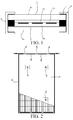
- the double-glass photovoltaic cell module includes a body 1, a reflecting coating 2, an end part sealing block 3, a frame 6, and a connection box 4.
- the body 1 includes a first glass layer 11, a first encapsulation layer 12, a cell group layer 13, a second encapsulation layer 14, and a second glass layer 15 that are sequentially disposed in laminated manner, where outer edges of the first glass layer 11 and the second glass layer 15 exceed outer edges of the first encapsulation layer 12, the cell group layer 13, and the second encapsulation layer 14.
- the first glass layer 11 may be common
- the second glass layer 15 may be common low iron ultra-white patterned tempered glass or common tempered glass.
- strength of the body 1 is enhanced, and a capability of the body 1 for load bearing is improved.
- Glass has extremely superior weather resistance, aging resistance, insulation resistance, and fire resistance performance, and abrasion resistance of glass is greatly higher than a backplane of polymers. Therefore, using glass as a backplane can well enhance aging resistance performance of a cell module, and pressure resistance and fire resistance performance of the double-glass photovoltaic cell module according to of the present disclosure are also improved.
- the reflecting coating 2 is provided on a side surface (a lower surface shown in FIG. 1 and FIG. 5 ), facing the cell group layer 13, of the second glass layer 15.
- the reflecting coating 2 is of a flat network shape, and the first glass layer 11 is frosted glass.
- the end part sealing block 3 is disposed between the first glass layer 11 and the second glass layer 15, and the end part sealing block 3 is located at peripheries of the first encapsulation layer 12/the cell group layer 13/the second encapsulation layer 14.
- the double-glass photovoltaic cell module is made by laminating the first glass layer 11, the first encapsulation layer 12, the cell group layer 13, the second encapsulation layer 14, the second glass layer 15, and the end part sealing block 3.
- a symbol "/" used in the descriptions of the present disclosure indicates "and".
- the frame 6 is encapsulated at a periphery of the body 1 by a sealant.
- the frame is fixed to an outside of the periphery of the body 1 by using silica gel, butyl rubber, or a double faced adhesive tape.
- the frame 6 has a notch 60, the connection box 4 is disposed at the notch 60, the connection box 4 is sealed and connected to the body 1 and the frame 6, the cell group layer 13 leads out a bus bar 131 between the first glass layer 11 and the second glass layer 15, and the connection box 4 is electrically connected to the bus bar 131 to extract energy of a cell.
- the disadvantage of the conventional photovoltaic module at which edge encapsulation materials are exposed may be overcome. Further, in a compact combination of the first glass layer and the second glass layer, water vapor and a corrosive gas in the environment can be well prevented from entering the module, attenuation of the module is slowed down, and a service life of the module is prolonged. By means of disposing a reflecting coating, a light running through a gap between cells can be reflected back to reduce encapsulation loss.
- the first glass layer 11 and the second glass layer 15 of the body 1 can be prevented to the greatest extent from being smashed, thereby protecting the cell module, which is convenient for transportation, and shows a longer service life.
- the bus bar 131 can be effectively led out from an edge of the body by using the frame 6.
- a cross section of the reflecting coating 2 is substantially of a triangular shape with a vertex angle being a circular arc, and the reflecting coating 2 is disposed corresponding to the gap between adjacent cells and/or an edge of a cell of the cell group layer 13. Therefore, referring to FIG. 5 , a light running from the first glass layer 11 to the gap between cells is reflected at the reflecting coating 2 of a triangle with a circular arc vertex angle. Then the light is incident to the first glass layer 11, and continues to be reflected to a cell for use. In this way, quantum of light utilization is further improved, and an output power of the cell module is improved.
- the reflecting coating 2 of the triangle with the circular arc vertex angle may not cause damage to the edge of the cell and the encapsulation film, and may be well fitted within the cell module, thereby increasing security and mechanical stability of the cell module, and prolonging the service life.
- the reflecting coatings disposed corresponding to the gap between the adjacent cells in the cell group layer 13 and/or the edge of a cell may be of an integrated network board structure.
- a curvature of the vertex angle of the triangle of the cross section of the reflecting coating 2 is ⁇ /6-5 ⁇ /6. Further, the curvature of the vertex angle of the triangle is ⁇ /4- ⁇ /2. More preferably, the curvature of the vertex angle of the triangle is ⁇ /3.
- a bottom angle ⁇ of a triangle formed by a cross section of the reflecting coating 2 is 15-85 degrees. Further, the bottom angle ⁇ of the triangle is 30-70 degrees. More preferably, the angle of the bottom angle ⁇ of the triangle is 60 degrees.
- the reflecting coating 2 is a white organic macromolecule layer, including but not limited to at least one selected from: a fluorocarbon resin layer, a diallyl isophthalate layer, a polyvinylidene fluoride layer, a polyethylene layer, a polytetrafluoroethylene layer, a fluorocarbon resin modified polymer layer, a diallyl isophthalate modified polymer layer, a polyvinylidene fluoride modified polymer layer, a polyethylene modified polymer layer, a polytetrafluoroethylene modified polymer layer, or a white silica-gel layer, which has features such as high reflectivity and excellent aging resistance performance.
- the reflecting coating 2 is closely adhered to a surface of a transparent layer by using processing processes including but not limited to spray coating, coating, and printing.
- connection box 4 is clamped to the outer edge of the body 1, and sealed and connected to the frame 6 by a sealant. Therefore, the connection box 3 is installed at the edge of the cell module, instead of opening a hole or a groove at the back of the module, which maintains a complete structure of the second glass layer 15, does not form a focal point of stress, and has higher security. Moreover, compared with the conventional module, such a deployment of the connection box 3 can reduce lengths of the bus bar inside and a cable outside of the module, reduce costs, reduce resistance, and increase power output.
- connection box 4 is glued to the first glass layer 11 and the second glass layer 15 of the body 1.
- the body 1 is formed as a rectangle, three connection boxes 4 are provided, spaced from one another and disposed on a short side of the body 1, every two adjacent connection boxes 4 are connected by using an encapsulation connector 8, and the encapsulation connector 8 encapsulates the outer edge, corresponding to the notch 60, of the body 1. Therefore, the encapsulation connector 8 and the frame 6 jointly protect edges of the body 1.
- edges of a conventional cell module are not protected or are only protected by using an adhesive tape.
- a module of such a structure has low security and great risks during transportation and installation because edges and sides of tempered glass would be easily stressed and cracked.
- the frame 6 and the encapsulation connector 8 may be made of multiple materials respectively.
- the frame 6 is an aluminum part, and the encapsulation connector 8 is an insulator. In this case, the frame 6 needs to be provided with a grounding hole 64.
- the frame 6 and the encapsulation connector 8 are both aluminum parts, and each encapsulation connector 8 between every two adjacent connection boxes 4 may be provided with one grounding hole 64.
- the frame 6 and the encapsulation connector 8 may both be insulators. In this case, neither the frame 6 nor the encapsulation connector 8 needs to be provided with a grounding hole 64.
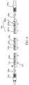
- the connection box 4 includes: a case 41 a, at least two partition plates 42a, a conductive block 43a, a diode 44a, and a connector member 45a.
- the case 41a has a chamber 410, and a side wall of the chamber 410 is provided with multiple threading holes 411.
- the bus bar 131 led out from the cell of the photovoltaic module is suitable for running through the threading hole 411 to enter the chamber 410, as shown in FIG. 6 and FIG. 7b .
- the at least two partition plates 42a are disposed inside the chamber 410 to divide the chamber 410 into at least three sub-chambers.
- the partition plate 42a may be a plastic part.
- the threading holes 411 are formed on side walls of two outermost sub-chambers of the at least three sub-chambers.
- the threading hole 411 is a rectangular hole, as shown in FIG. 7b .
- the conductive block 43a is disposed inside the chamber 410 and runs through the at least three sub-chambers, which prolongs a length of the conductive block 43a.
- the bus bar 131 is suitable for being in welded connection with the conductive block 43a to extract energy of a cell.
- the diode 44a is disposed inside a middle sub-chamber of the at least three sub-chambers, so as to prevent the cell from burning out when a hot-spot effect occurs, and prevent a current from flowing backwards when there is no light.
- the diode 44a is electrically connected to the conductive block 43a, and preferably, the diode 44a is welded to the conductive block 43a.
- the connector member 45a is located outside of the case 41a and is connected to the conductive block 43a by a cable 46a.
- the connection box 4 includes the chamber 410, which is further divided into multiple sub-chambers by the partition plates 42a, the diode 44a is disposed inside the middle sub-chamber.
- the diode 44a When the bus bar 131 is being welded, a welding position of the diode 44a will not melt, which may prevent the diode from being welded off.
- the diode 44a or the connection box 4 is invalid, only the bus bar 131 needs to be welded off, or the bus bar 131 needs to be taken out from the threading hole 411, and then the connection box can be removed. Operations are convenient and time-saving, which is easy for power station maintenance, and prolongs a service life of the module.
- the photovoltaic cell module according to this embodiment of the present disclosure may further include a surface mount thin sheet diode 9.
- the thin sheet diode 9 is welded to the bus bar 131 and is laminated between the first glass layer 11 and the second glass layer 15, so as to prevent the cell from burning out when a hot-spot effect occurs, and prevent a current from flowing backwards when there is no light.
- two partition plates 42a are provided, and the two partition plates 42a divide the chamber 410 into three sub-chambers, including a first sub-chamber 401 a, a second sub-chamber 402a, and a third sub-chamber 403a.
- the diode 44a is disposed inside the middle sub-chamber 402a, as shown in FIG. 6 .
- the sub-chamber in which the diode 44a is located is the second sub-chamber 402a, and is sealed by potting glue. Therefore, potting glue with favorable conductivity for heat can be kept around the diode 44a, which can promptly reduce a temperature of the diode, thereby protecting the diode.
- the first sub-chamber 401a and the third sub-chamber 403a may remain empty, or may receive potting glue.
- the case 41a includes a box seat and a box cover (not shown in the figure) which are clamped to each other, and sealed together by butyl rubber, thereby ensuring water resistance of the connection box.
- connection box according to the embodiments of the present disclosure with reference to FIG. 6 .
- Descriptions are provided by using an example in which the bus bar 131 is welded to the conductive block 43a.
- the bus bar 131 led out from the cell of the photovoltaic module runs through the threading hole 411 and extends into the first sub-chamber 401a and the third sub-chamber 403a.
- the bus bar 131 is welded to the conductive block 43a.
- the potting glue is poured into the second sub-chamber 402a in which the diode 44a is located, thereby completing installation of the connection box.
- connection box With the connection box according to the embodiments of the present disclosure, some existing problems that it is difficult to replace a connection box, and a diode is easily to be welded off when a bus bar is being welded, are resolved, and a service life may be prolonged, which can achieve an extremely long warranty period of 40 years.
- the double-glass photovoltaic cell module includes a surface mount thin sheet diode 9.
- the thin sheet diode 9 is welded to the bus bar 131 and is laminated between the first glass layer 11 and the second glass layer 15, so as to prevent the cell from burning out when a hot-spot effect occurs, and prevent a current from flowing backwards when there is no light.
- two connection boxes 4 are provided, each connection box is of an L shape. The two connection boxes 4 are disposed at two adjacent corners of the body 1, and the bus bar 131 extends into the connection box 4 to extract energy of the cell.
- the thin sheet diode 9 is directly welded to the bus bar 131, the bus bar 131 is led out from two ends, and respectively welded to a positive connection box and a negative connection box disposed at two corners of the body 1, as shown in FIG. 8 to FIG. 10 .
- a length of a side of the thin sheet diode 9 is 8-12 mm.
- a material of the connection box 4 may be porcelain and, therefore, tolerance to the environment can be improved.
- the material of the connection box 4 may be plastic.
- the receiving groove 16 is formed on the second glass layer 15.
- the receiving groove 16 is a square groove, and a length of a side of the receiving groove 16 is 0.2 mm greater than a length of a side of the diode 9.
- the diode 9 is basically in close contact with the first glass layer 11 and the second glass layer 15 that are located respectively above and below the diode 9, so that heat generated by the diode 9 can be conducted out.
- the connection box 4 includes: a case 41b, a conductive sheet 42b, and a connector member 43b, where the case 41b has a chamber 410b, a side wall of the chamber 410b is provided with a threading hole 411b (as shown in FIG. 5 ).
- the threading hole 11 is a rectangular hole.
- the conductive sheet 42b is disposed inside the chamber 410b, where the bus bar 131 runs through the threading hole 411b, extends into the chamber 410b, and is connected to the conductive sheet 42b, and the connector member 43b is located outside the case 41b and is connected to the conductive block by using a cable 44b.
- the bus bar 131 and the conductive sheet 42b may be in welded connection or in clamped connection.
- the double-glass photovoltaic cell module resolves existing problems that it is difficult to replace a connection box, and that a diode is easily welded off when a bus bar is welded, and prolongs a service life.
- the connection box may be easily installed, and fewer cables and bus bars are required, thereby reducing resistance and increasing power output.
- the end part sealing block 3 may be a butyl rubber member or a polyisobutylene rubber member, or an assembly glue member having a water vapor transmission rate lower than 0.01g/m2/day, thereby making up a disadvantage of exposing encapsulation materials of edges of the conventional photovoltaic module.
- the double-glass cell module according to the present disclosure has favorable weather resistance, high structural strength, a longer service life, and high ultraviolet absorbance.
- the double-glass photovoltaic cell module according to the present disclosure may further include multiple fixing devices 5, disposed on a side surface, far from the cell group layer 13, of the second glass layer 15, configured to install the entire cell module in a position by using the fixing devices 5.
- the fixing devices 5 are stuck to the back of the cell module by using high strength assembly glue. Therefore, the fixing devices 5 can be fixed, by using screws, to a support (not shown in the figure) for fixing the cell module.
- Such an installation manner ensures that the cell module is more evenly stressed, thereby enhancing a capability of the module for load bearing, and making the module more secure and reliable.
- the fixing device 5 is provided with a locating member used for fixing the double-glass cell module to an external carrier.
- four fixing devices 5 are provided and evenly distributed on a surface of the second glass layer 15, that is, the back of the entire cell module. Therefore, it may be convenient to install the entire cell module on an installation surface or in an installation support (not shown in the figure).
- the frame 6 may be fixed to an outside of the periphery of the body 1 by using silica gel, butyl rubber, or a double faced adhesive tape.
- the frame 6 is formed to be a frame structure, and a cross section of the frame 6 has a U-shaped groove, where a groove opening width of the U-shaped groove is greater than a thickness of the body 1, so that the U-shaped groove covers an outer edge of the body 1.
- a thickness of the frame 6 is 1-2 mm, that is, a thickness of each side of the U-shaped groove of the frame 6 is 1-2 mm.
- a convex bar 62 is formed on an outer surface the frame 6, as shown in FIG. 3 .
- the convex bar 62 extends along a length direction of the frame 6.
- the convex bar 62 extends along a length direction of the frame 6 in a straight line or in a curved line, or may be extended, for example, spirally.
- the frame 6 is an integrated frame formed by bending an encapsulated bar.
- the encapsulation bar is a continuous conductor, where the encapsulation bar has at least two predetermined bending positions, a V-shaped groove 63 of 90 degrees is formed in each predetermined bending position, and the encapsulation bar is provided with a grounding hole 64.
- a reason for using a continuous frame conductor is: if each segment of side of the frame conductor is not continuous, when the cell module is installed, each segment of the side needs to be grounded, which increases costs, and makes installation difficult.
- a diameter of the grounding hole 64 is 2-4 mm.
- the V-shaped grooves 63 can be directly formed through bending during installation. In this way, the bended V-shaped grooves 63 of 90 degrees exactly form corners of the frame.
- the frame 6 and the connector 4 are both insulated polymer material members, the frame 6 does not need to be provided with a grounding hole 64 and multiple V-shaped grooves 63; instead, a required size is directly cut out for installation by segmentations, that is, the frame 6 is sequentially connected to the connector 4.
- the first encapsulation layer 12 and the second encapsulation layer 14 are transparent silica-gel layers or polyolefin layers, which therefore, compared with a conventional EVA encapsulation film, have an advantage of being capable of letting an ultraviolet light absorbed by an EVA ultraviolet absorber run through, and then the run through ultraviolet light may be converted into electrical energy, thus to increase outputs of the photovoltaic module.
- a transparent silica-gel layer or a polyolefin layer is stable under the ultraviolet light, which may not be degraded to produce a small molecule such as acetic acid to erode a cell, and may have better weather resistance performance.
- transparent silica gel is of a film-shaped structure, is thermoplastic, is in a solid state at ordinary temperature, and is gradually softened after elevation of temperature. Because transparent liquid silica gel is bi-component silica gel, and is in a liquid state at ordinary temperature, after two components are uniformly mixed with a radio of 1:1 and laminated at 50-130, thermosetting transparent silica gel may be obtained by curing under a low laminating temperature, which may save energy and help to prolong a service life of a laminating machine.
- a backplane and a front plate of a double-glass module are both rigid glass, on which gluing and lamination are easier to be performed than a conventional backplane of polymer materials.
- the polyolefin layers are thermosetting polyolefin layers or thermoplastic polyolefin layers.
- the temperature of the module may reach 80-100 , a thermoplastic film is softened and has particular fluidity, but a thermosetting film does not have such a problem; therefore, heat resistance performance of the module is better.
- the double-glass photovoltaic cell module according to the present disclosure has favorable weather resistance, high structural strength, a longer service life, and high ultraviolet absorbance.
Landscapes
- Photovoltaic Devices (AREA)
- Life Sciences & Earth Sciences (AREA)
- Sustainable Development (AREA)
Applications Claiming Priority (2)
| Application Number | Priority Date | Filing Date | Title |
|---|---|---|---|
| CN201310737528.2A CN104752538A (zh) | 2013-12-27 | 2013-12-27 | 双玻光伏电池组件 |
| PCT/CN2014/084543 WO2015096490A1 (fr) | 2013-12-27 | 2014-08-15 | Module cellule photovoltaïque à double verre |
Publications (2)
| Publication Number | Publication Date |
|---|---|
| EP3089355A1 true EP3089355A1 (fr) | 2016-11-02 |
| EP3089355A4 EP3089355A4 (fr) | 2017-01-11 |
Family
ID=53477483
Family Applications (1)
| Application Number | Title | Priority Date | Filing Date |
|---|---|---|---|
| EP14875670.3A Withdrawn EP3089355A4 (fr) | 2013-12-27 | 2014-08-15 | Module cellule photovoltaïque à double verre |
Country Status (6)
| Country | Link |
|---|---|
| US (1) | US10186625B2 (fr) |
| EP (1) | EP3089355A4 (fr) |
| JP (1) | JP2017501584A (fr) |
| KR (1) | KR20160090898A (fr) |
| CN (1) | CN104752538A (fr) |
| WO (1) | WO2015096490A1 (fr) |
Cited By (1)
| Publication number | Priority date | Publication date | Assignee | Title |
|---|---|---|---|---|
| US20190291403A1 (en) * | 2016-10-27 | 2019-09-26 | voestalpine Automotive Components Dettingen GmbH & Co. KG | Apparatus and method for bonding sheet metal parts to a laminated core |
Families Citing this family (34)
| Publication number | Priority date | Publication date | Assignee | Title |
|---|---|---|---|---|
| CN105489540A (zh) * | 2015-12-02 | 2016-04-13 | 山东新华联新能源科技有限公司 | 双玻光伏组件的防错位装置及双玻光伏组件的封装方法 |
| US11489483B2 (en) | 2015-12-09 | 2022-11-01 | Brian Patrick Janowski | Solar window construction and methods |
| CN105429584A (zh) * | 2015-12-31 | 2016-03-23 | 徐秀萍 | 一种光伏组件 |
| CN105471385A (zh) * | 2015-12-31 | 2016-04-06 | 徐秀萍 | 一种光伏组件 |
| WO2018097282A1 (fr) * | 2016-11-28 | 2018-05-31 | 京セラ株式会社 | Module de cellules solaires |
| CN106684187A (zh) * | 2016-12-19 | 2017-05-17 | 张家港长丰能源有限公司 | 一种封闭式快拆太阳能电池组件 |
| CN106788189B (zh) * | 2016-12-26 | 2018-10-12 | 江苏林洋新能源科技有限公司 | 一种光伏组件固定装置及其安装方法 |
| CN108251044B (zh) * | 2016-12-28 | 2020-12-25 | 比亚迪股份有限公司 | 一种有机硅底涂液和双玻组件 |
| WO2018132491A1 (fr) * | 2017-01-10 | 2018-07-19 | Ubiquitous Energy, Inc. | Module photovoltaïque transparent intégré à une fenêtre |
| CN107070375B (zh) * | 2017-05-08 | 2019-07-02 | 中科电建新能源股份有限公司 | 一种太阳能光伏固定支架 |
| CN107086853A (zh) * | 2017-05-15 | 2017-08-22 | 苏州快可光伏电子股份有限公司 | 一种双玻双面发电光伏组件接线盒 |
| TWI661668B (zh) | 2017-07-25 | 2019-06-01 | 海力雅集成股份有限公司 | 太陽能模組 |
| CN108444952B (zh) * | 2018-01-17 | 2020-10-09 | 陕西师范大学 | 一种石墨烯阵列检测单元及其制备方法、检测转换装置 |
| CN108264014B (zh) * | 2018-01-17 | 2020-09-11 | 陕西师范大学 | 一种金属阵列检测单元及其制备方法、检测转换装置 |
| WO2019160264A1 (fr) * | 2018-02-14 | 2019-08-22 | 엘지전자 주식회사 | Module de cellules solaires comprenant une cellule solaire de pérovskite et son procédé de fabrication |
| CN108376720A (zh) * | 2018-04-23 | 2018-08-07 | 黑龙江华夏易能新能源科技有限公司 | 一种光伏电池组件及其制作方法 |
| CN109450371A (zh) * | 2018-12-20 | 2019-03-08 | 苏州腾晖光伏技术有限公司 | 一种双面双玻光伏组件 |
| CN109860320A (zh) * | 2019-01-17 | 2019-06-07 | 北京汉能光伏投资有限公司 | 光伏组件及其制备方法 |
| CN110649116B (zh) * | 2019-09-30 | 2023-06-09 | 常州斯威克光伏新材料有限公司 | 一种太阳能电池用多层封装胶膜 |
| CN111354813B (zh) * | 2020-04-20 | 2026-01-27 | 珠海格力电器股份有限公司 | 光伏组件及其制造方法 |
| EP4170899B1 (fr) * | 2020-07-04 | 2025-08-13 | Sunman (Zhenjiang) Co., Ltd. | Structure de réseau photovoltaïque à faible perte de ligne |
| CN112038431B (zh) * | 2020-08-14 | 2022-04-08 | 泰州隆基乐叶光伏科技有限公司 | 一种光伏组件及其封装方法 |
| CN112477176B (zh) * | 2020-12-02 | 2025-05-13 | 苏州德睿联智能装备科技有限公司 | 一种全自动汇流条隔离片放置机 |
| CN112599625B (zh) * | 2020-12-15 | 2022-12-27 | 江西仁江科技有限公司 | 光伏幕墙双玻组件 |
| CN115841962A (zh) * | 2021-09-18 | 2023-03-24 | 泰州隆基乐叶光伏科技有限公司 | 一种电池片的电学性能测试方法 |
| CN113707745B (zh) | 2021-10-26 | 2022-06-21 | 浙江晶科能源有限公司 | 一种光伏组件 |
| WO2023092257A1 (fr) * | 2021-11-23 | 2023-06-01 | China Triumph International Engineering Co., Ltd. | Procédé de production d'un module photovoltaïque pourvu d'une protection de bord, et module photovoltaïque pourvu d'une protection de bord |
| CN114335220A (zh) * | 2021-12-31 | 2022-04-12 | 江苏润达光伏无锡有限公司 | 一种基于硅胶的光伏组件封装方法 |
| CN114512562B (zh) * | 2022-01-29 | 2024-07-19 | 福斯特(嘉兴)新材料有限公司 | 双玻组件及其封装方法、电子元器件 |
| IL300356A (en) * | 2022-12-22 | 2024-07-01 | Clearvue Tech Ltd | A window unit for a building or structure |
| CN116404979A (zh) * | 2023-04-21 | 2023-07-07 | 广东金源光能股份有限公司 | 反光汇流条及其光伏组件 |
| CN116915155B (zh) * | 2023-07-25 | 2024-06-11 | 江苏悦阳光伏科技有限公司 | 一种基于双玻结构的光伏组件及生产工艺 |
| CN118507566B (zh) * | 2024-05-29 | 2025-12-26 | 正信光电科技股份有限公司 | 一种长寿命hjt双面双玻电池组件 |
| CN118571968A (zh) * | 2024-07-30 | 2024-08-30 | 比亚迪股份有限公司 | 太阳能电池组件和具有其的用电设备 |
Family Cites Families (42)
| Publication number | Priority date | Publication date | Assignee | Title |
|---|---|---|---|---|
| JPH10256576A (ja) * | 1997-03-06 | 1998-09-25 | Matsushita Electric Ind Co Ltd | 太陽電池シート |
| JP3738129B2 (ja) * | 1998-04-14 | 2006-01-25 | 三洋電機株式会社 | 太陽電池モジュール |
| JP2001352014A (ja) * | 2000-06-06 | 2001-12-21 | Canon Inc | 半導体装置及び太陽電池モジュール |
| JP2002158368A (ja) * | 2000-11-21 | 2002-05-31 | Sanyo Electric Co Ltd | 太陽電池モジュール |
| DE20117716U1 (de) * | 2001-10-23 | 2002-03-14 | Würth Solar GmbH & Co. KG, 71672 Marbach | Rahmen für Solarmodule |
| JP2003188399A (ja) * | 2001-12-19 | 2003-07-04 | Fuji Electric Co Ltd | 太陽電池モジュール |
| JP2005072283A (ja) * | 2003-08-25 | 2005-03-17 | Kyocera Corp | 太陽電池モジュール |
| JP2005150318A (ja) * | 2003-11-14 | 2005-06-09 | Canon Inc | 太陽電池モジュール及びその製造方法 |
| US8039731B2 (en) * | 2005-06-06 | 2011-10-18 | General Electric Company | Photovoltaic concentrator for solar energy system |
| JP5581590B2 (ja) * | 2007-01-31 | 2014-09-03 | 東レ株式会社 | 白色ポリエステルフィルムおよび反射シート |
| US20080185033A1 (en) * | 2007-02-06 | 2008-08-07 | Kalejs Juris P | Solar electric module |
| US20090178704A1 (en) * | 2007-02-06 | 2009-07-16 | Kalejs Juris P | Solar electric module with redirection of incident light |
| US20090114261A1 (en) * | 2007-08-29 | 2009-05-07 | Robert Stancel | Edge Mountable Electrical Connection Assembly |
| US20100012172A1 (en) * | 2008-04-29 | 2010-01-21 | Advent Solar, Inc. | Photovoltaic Modules Manufactured Using Monolithic Module Assembly Techniques |
| US20100175743A1 (en) | 2009-01-09 | 2010-07-15 | Solopower, Inc. | Reliable thin film photovoltaic module structures |
| US20120048349A1 (en) | 2009-01-09 | 2012-03-01 | Solopower, Inc. | Flexible solar modules and manufacturing the same |
| JP2010165750A (ja) * | 2009-01-13 | 2010-07-29 | Mitsubishi Electric Corp | 太陽電池モジュール |
| JP5361438B2 (ja) * | 2009-02-23 | 2013-12-04 | 三洋電機株式会社 | 太陽電池モジュール |
| US20110036390A1 (en) * | 2009-08-11 | 2011-02-17 | Miasole | Composite encapsulants containing fillers for photovoltaic modules |
| JP2011108725A (ja) * | 2009-11-13 | 2011-06-02 | Toppan Printing Co Ltd | 裏面シート、太陽電池裏面シート及びこれを用いた太陽電池モジュール |
| JP5719647B2 (ja) | 2010-04-09 | 2015-05-20 | 日東電工株式会社 | シーリング組成物、複層ガラスおよび太陽電池パネル |
| DE112011101537T5 (de) | 2010-04-26 | 2013-02-28 | E.I. Du Pont De Nemours And Co. | Verteilerkasten, Rahmenkomponente und Solarzellenmodul |
| CN102237423B (zh) * | 2010-04-26 | 2014-05-07 | 杜邦公司 | 接线盒、边框组件及太阳能电池模块 |
| JP2012015442A (ja) * | 2010-07-05 | 2012-01-19 | Toppan Printing Co Ltd | 裏面保護シート及びそれを用いた太陽電池 |
| CN102403385A (zh) | 2010-09-07 | 2012-04-04 | 杜邦公司 | 薄膜太阳能电池模块 |
| KR20120080336A (ko) * | 2011-01-07 | 2012-07-17 | 삼성전기주식회사 | 백색 백시트를 구비한 태양전지 모듈 |
| JP2013065708A (ja) * | 2011-09-16 | 2013-04-11 | Keiwa Inc | 太陽電池モジュール、太陽電池モジュール用バックシート、太陽電池セル間配設用スペーサ及び太陽電池モジュールの製造方法 |
| CN202268367U (zh) * | 2011-09-29 | 2012-06-06 | 晶科能源有限公司 | 新型太阳能光伏组件 |
| KR101327014B1 (ko) * | 2011-11-29 | 2013-11-13 | 엘지이노텍 주식회사 | 태양전지 모듈 및 그 제조방법 |
| CN103165705B (zh) * | 2011-12-08 | 2015-11-25 | 杜邦公司 | 太阳能电池模块 |
| CN202513178U (zh) | 2012-03-22 | 2012-10-31 | 山东中晶新能源有限公司 | 大功率加厚高透双玻光伏组件 |
| CN202601674U (zh) * | 2012-05-04 | 2012-12-12 | 浙江尖山光电股份有限公司 | 一种强吸光性双玻组件 |
| US20130306130A1 (en) * | 2012-05-21 | 2013-11-21 | Stion Corporation | Solar module apparatus with edge reflection enhancement and method of making the same |
| JP5780209B2 (ja) * | 2012-05-29 | 2015-09-16 | 信越化学工業株式会社 | 太陽電池モジュールの製造方法 |
| WO2013183395A1 (fr) * | 2012-06-04 | 2013-12-12 | シャープ株式会社 | Module de batterie solaire et procédé de fabrication de module de batterie solaire |
| CN203013755U (zh) * | 2012-11-15 | 2013-06-19 | 杜邦公司 | 光伏模块及其集成型边框 |
| CN102969384B (zh) * | 2012-12-20 | 2015-08-19 | 英利能源(中国)有限公司 | 一种太阳能电池组件及其封装方法 |
| WO2014146317A1 (fr) * | 2013-03-22 | 2014-09-25 | 韩华新能源(启东)有限公司 | Nouveau module photovoltaïque |
| CN203774347U (zh) | 2013-12-27 | 2014-08-13 | 比亚迪股份有限公司 | 光伏电池组件 |
| CN203813724U (zh) | 2013-12-27 | 2014-09-03 | 比亚迪股份有限公司 | 双玻光伏电池组件及其边框 |
| CN203746872U (zh) | 2013-12-27 | 2014-07-30 | 比亚迪股份有限公司 | 双玻电池组件 |
| CN203746873U (zh) * | 2013-12-27 | 2014-07-30 | 比亚迪股份有限公司 | 光伏电池组件 |
-
2013
- 2013-12-27 CN CN201310737528.2A patent/CN104752538A/zh active Pending
-
2014
- 2014-08-15 US US15/107,816 patent/US10186625B2/en not_active Expired - Fee Related
- 2014-08-15 EP EP14875670.3A patent/EP3089355A4/fr not_active Withdrawn
- 2014-08-15 JP JP2016543178A patent/JP2017501584A/ja active Pending
- 2014-08-15 KR KR1020167017236A patent/KR20160090898A/ko not_active Ceased
- 2014-08-15 WO PCT/CN2014/084543 patent/WO2015096490A1/fr not_active Ceased
Cited By (1)
| Publication number | Priority date | Publication date | Assignee | Title |
|---|---|---|---|---|
| US20190291403A1 (en) * | 2016-10-27 | 2019-09-26 | voestalpine Automotive Components Dettingen GmbH & Co. KG | Apparatus and method for bonding sheet metal parts to a laminated core |
Also Published As
| Publication number | Publication date |
|---|---|
| CN104752538A (zh) | 2015-07-01 |
| JP2017501584A (ja) | 2017-01-12 |
| KR20160090898A (ko) | 2016-08-01 |
| EP3089355A4 (fr) | 2017-01-11 |
| US10186625B2 (en) | 2019-01-22 |
| US20160315209A1 (en) | 2016-10-27 |
| WO2015096490A1 (fr) | 2015-07-02 |
Similar Documents
| Publication | Publication Date | Title |
|---|---|---|
| US10186625B2 (en) | Double-glass photovoltaic cell module | |
| US9997658B2 (en) | Photovoltaic cell module | |
| EP3089220A1 (fr) | Module photovoltaïque | |
| EP3089221B1 (fr) | Module photovoltaïque double verre | |
| US9353973B2 (en) | Concentrating photovoltaic-thermal solar energy collector | |
| CN104377259A (zh) | 双玻光伏电池组件 | |
| CN203746872U (zh) | 双玻电池组件 | |
| CN203813724U (zh) | 双玻光伏电池组件及其边框 | |
| WO2010013691A1 (fr) | Module de cellule solaire | |
| US20160064588A1 (en) | Concentrator lens for directing light to a photovoltaic target or mirrored surface and a dynamic window apparatus utilizing the same | |
| EP3163629A1 (fr) | Module photovoltaïque semi-élastique | |
| CN219286428U (zh) | 光伏组件 | |
| CN221427751U (zh) | 光伏组件及光伏阵列 | |
| CN223872672U (zh) | 光伏层压件和光伏组件 | |
| US20260081559A1 (en) | Photovoltaic assembly | |
| CN113299784B (zh) | 光伏组件和光伏组件的制造方法 | |
| CN121126973A (zh) | 透明膜带、光伏组件及光伏组件封装方法 | |
| CN106784337A (zh) | 一种具有散热功能的有机太阳能电池组件 |
Legal Events
| Date | Code | Title | Description |
|---|---|---|---|
| PUAI | Public reference made under article 153(3) epc to a published international application that has entered the european phase |
Free format text: ORIGINAL CODE: 0009012 |
|
| 17P | Request for examination filed |
Effective date: 20160715 |
|
| AK | Designated contracting states |
Kind code of ref document: A1 Designated state(s): AL AT BE BG CH CY CZ DE DK EE ES FI FR GB GR HR HU IE IS IT LI LT LU LV MC MK MT NL NO PL PT RO RS SE SI SK SM TR |
|
| AX | Request for extension of the european patent |
Extension state: BA ME |
|
| A4 | Supplementary search report drawn up and despatched |
Effective date: 20161208 |
|
| RIC1 | Information provided on ipc code assigned before grant |
Ipc: H02S 30/10 20140101AFI20161202BHEP Ipc: H01L 31/048 20140101ALI20161202BHEP |
|
| DAX | Request for extension of the european patent (deleted) | ||
| STAA | Information on the status of an ep patent application or granted ep patent |
Free format text: STATUS: EXAMINATION IS IN PROGRESS |
|
| 17Q | First examination report despatched |
Effective date: 20180308 |
|
| STAA | Information on the status of an ep patent application or granted ep patent |
Free format text: STATUS: THE APPLICATION IS DEEMED TO BE WITHDRAWN |
|
| 18D | Application deemed to be withdrawn |
Effective date: 20190904 |