EP3089409A1 - Verfahren und system zur wiederherstellung von qos-verschlechterungen in mpls-netzwerken - Google Patents
Verfahren und system zur wiederherstellung von qos-verschlechterungen in mpls-netzwerken Download PDFInfo
- Publication number
- EP3089409A1 EP3089409A1 EP13900511.0A EP13900511A EP3089409A1 EP 3089409 A1 EP3089409 A1 EP 3089409A1 EP 13900511 A EP13900511 A EP 13900511A EP 3089409 A1 EP3089409 A1 EP 3089409A1
- Authority
- EP
- European Patent Office
- Prior art keywords
- network
- mpls
- alarm
- monitoring
- services
- Prior art date
- Legal status (The legal status is an assumption and is not a legal conclusion. Google has not performed a legal analysis and makes no representation as to the accuracy of the status listed.)
- Withdrawn
Links
- 238000000034 method Methods 0.000 title claims abstract description 90
- 230000006866 deterioration Effects 0.000 title 1
- 238000012544 monitoring process Methods 0.000 claims abstract description 134
- 230000015556 catabolic process Effects 0.000 claims abstract description 45
- 238000006731 degradation reaction Methods 0.000 claims abstract description 45
- 238000012360 testing method Methods 0.000 claims abstract description 35
- 230000011664 signaling Effects 0.000 claims abstract description 15
- 230000001960 triggered effect Effects 0.000 claims abstract description 10
- 238000004891 communication Methods 0.000 claims description 18
- 230000002596 correlated effect Effects 0.000 claims description 6
- 238000004590 computer program Methods 0.000 claims description 4
- 230000004044 response Effects 0.000 abstract description 26
- 230000007246 mechanism Effects 0.000 description 38
- 238000007726 management method Methods 0.000 description 32
- 238000005259 measurement Methods 0.000 description 26
- 238000001514 detection method Methods 0.000 description 19
- 230000008569 process Effects 0.000 description 12
- 239000000523 sample Substances 0.000 description 11
- 102100021122 DNA damage-binding protein 2 Human genes 0.000 description 9
- 101001041466 Homo sapiens DNA damage-binding protein 2 Proteins 0.000 description 9
- 238000013459 approach Methods 0.000 description 7
- 230000006735 deficit Effects 0.000 description 7
- 239000000243 solution Substances 0.000 description 7
- 230000008901 benefit Effects 0.000 description 5
- 230000000875 corresponding effect Effects 0.000 description 5
- 238000005516 engineering process Methods 0.000 description 5
- 230000001965 increasing effect Effects 0.000 description 5
- 230000012010 growth Effects 0.000 description 4
- 230000002265 prevention Effects 0.000 description 4
- 238000012545 processing Methods 0.000 description 4
- 238000012986 modification Methods 0.000 description 3
- 230000004048 modification Effects 0.000 description 3
- 230000007547 defect Effects 0.000 description 2
- 238000010586 diagram Methods 0.000 description 2
- 238000005538 encapsulation Methods 0.000 description 2
- 238000002347 injection Methods 0.000 description 2
- 239000007924 injection Substances 0.000 description 2
- 230000003993 interaction Effects 0.000 description 2
- 238000012423 maintenance Methods 0.000 description 2
- 230000003449 preventive effect Effects 0.000 description 2
- 238000011084 recovery Methods 0.000 description 2
- 238000012956 testing procedure Methods 0.000 description 2
- 230000002457 bidirectional effect Effects 0.000 description 1
- 230000005540 biological transmission Effects 0.000 description 1
- 210000004556 brain Anatomy 0.000 description 1
- 230000000295 complement effect Effects 0.000 description 1
- 238000012790 confirmation Methods 0.000 description 1
- 230000007812 deficiency Effects 0.000 description 1
- 230000003111 delayed effect Effects 0.000 description 1
- 230000001419 dependent effect Effects 0.000 description 1
- 238000009795 derivation Methods 0.000 description 1
- 238000011161 development Methods 0.000 description 1
- 230000018109 developmental process Effects 0.000 description 1
- 239000006185 dispersion Substances 0.000 description 1
- 230000002708 enhancing effect Effects 0.000 description 1
- 230000001771 impaired effect Effects 0.000 description 1
- 238000007689 inspection Methods 0.000 description 1
- 230000004807 localization Effects 0.000 description 1
- 238000001310 location test Methods 0.000 description 1
- 238000013508 migration Methods 0.000 description 1
- 230000005012 migration Effects 0.000 description 1
- 230000000737 periodic effect Effects 0.000 description 1
- 238000012805 post-processing Methods 0.000 description 1
- 238000000275 quality assurance Methods 0.000 description 1
- 238000005070 sampling Methods 0.000 description 1
- 230000007727 signaling mechanism Effects 0.000 description 1
Images


Classifications
-
- H—ELECTRICITY
- H04—ELECTRIC COMMUNICATION TECHNIQUE
- H04L—TRANSMISSION OF DIGITAL INFORMATION, e.g. TELEGRAPHIC COMMUNICATION
- H04L12/00—Data switching networks
- H04L12/64—Hybrid switching systems
- H04L12/6418—Hybrid transport
-
- H—ELECTRICITY
- H04—ELECTRIC COMMUNICATION TECHNIQUE
- H04L—TRANSMISSION OF DIGITAL INFORMATION, e.g. TELEGRAPHIC COMMUNICATION
- H04L41/00—Arrangements for maintenance, administration or management of data switching networks, e.g. of packet switching networks
- H04L41/06—Management of faults, events, alarms or notifications
- H04L41/0604—Management of faults, events, alarms or notifications using filtering, e.g. reduction of information by using priority, element types, position or time
- H04L41/0618—Management of faults, events, alarms or notifications using filtering, e.g. reduction of information by using priority, element types, position or time based on the physical or logical position
-
- H—ELECTRICITY
- H04—ELECTRIC COMMUNICATION TECHNIQUE
- H04L—TRANSMISSION OF DIGITAL INFORMATION, e.g. TELEGRAPHIC COMMUNICATION
- H04L41/00—Arrangements for maintenance, administration or management of data switching networks, e.g. of packet switching networks
- H04L41/06—Management of faults, events, alarms or notifications
- H04L41/0654—Management of faults, events, alarms or notifications using network fault recovery
- H04L41/0659—Management of faults, events, alarms or notifications using network fault recovery by isolating or reconfiguring faulty entities
-
- H—ELECTRICITY
- H04—ELECTRIC COMMUNICATION TECHNIQUE
- H04L—TRANSMISSION OF DIGITAL INFORMATION, e.g. TELEGRAPHIC COMMUNICATION
- H04L45/00—Routing or path finding of packets in data switching networks
- H04L45/22—Alternate routing
-
- H—ELECTRICITY
- H04—ELECTRIC COMMUNICATION TECHNIQUE
- H04L—TRANSMISSION OF DIGITAL INFORMATION, e.g. TELEGRAPHIC COMMUNICATION
- H04L67/00—Network arrangements or protocols for supporting network services or applications
- H04L67/50—Network services
- H04L67/52—Network services specially adapted for the location of the user terminal
-
- H—ELECTRICITY
- H04—ELECTRIC COMMUNICATION TECHNIQUE
- H04L—TRANSMISSION OF DIGITAL INFORMATION, e.g. TELEGRAPHIC COMMUNICATION
- H04L12/00—Data switching networks
- H04L12/54—Store-and-forward switching systems
- H04L12/56—Packet switching systems
- H04L12/5601—Transfer mode dependent, e.g. ATM
- H04L2012/5625—Operations, administration and maintenance [OAM]
- H04L2012/5627—Fault tolerance and recovery
-
- H—ELECTRICITY
- H04—ELECTRIC COMMUNICATION TECHNIQUE
- H04L—TRANSMISSION OF DIGITAL INFORMATION, e.g. TELEGRAPHIC COMMUNICATION
- H04L45/00—Routing or path finding of packets in data switching networks
- H04L45/28—Routing or path finding of packets in data switching networks using route fault recovery
-
- H—ELECTRICITY
- H04—ELECTRIC COMMUNICATION TECHNIQUE
- H04L—TRANSMISSION OF DIGITAL INFORMATION, e.g. TELEGRAPHIC COMMUNICATION
- H04L45/00—Routing or path finding of packets in data switching networks
- H04L45/50—Routing or path finding of packets in data switching networks using label swapping, e.g. multi-protocol label switch [MPLS]
Definitions
- the present invention has its application within the telecommunication sector, especially, relates to Quality Assurance in computer networks and, more particularly, refers to a system and method for preventing, detecting and restoring Quality of Service (QoS) degradations in End-to-End (E2E) MultiProtocol Label Switching (MPLS) networks.
- QoS Quality of Service
- E2E End-to-End
- MPLS MultiProtocol Label Switching
- IP Core networks are usually deployed over Multiprotocol Label Switching (MPLS) technology due to the wide range of benefits that this encapsulation provides, in terms of Traffic Engineering (TE), homogeneous provision of any type of service, restoration tools and Quality of Service (QoS) maintenance.
- MPLS has also experienced an extension to other existing segments, like regional networks.
- these MPLS domains have normally been kept separated, at least in large operators, mainly due to scalability causes.
- E2E MPLS networks which means scalable MPLS transport over any type of access and layer-1 technologies, at any network segment (and between any network segment) and for any type of service.
- all network routers distributed routers, edge routers and metro routers
- PWs Pseudo-Wires
- OAM Operation, Administration and Maintenance
- the total fault time (i.e. the time during which the service is unavailable) is composed of three time intervals.
- the process comprises the following three steps: after a fault happens, first step (i) is to detect that it has happened, then (ii) to locate where it has happened, and finally (iii) to restore it.
- a goal of any fault management system should be to reduce to the maximum possible the total fault time.
- MPLS restoration There is still an additional functionality that plays an important role once a failure is detected and located: MPLS restoration.
- Restoration mechanisms need to be triggered to restore the client traffic flows, i.e., to inject them over an alternative path which does not present any fault.
- MPLS there exist several procedures to achieve such behavior, being Fast-Reroute (FRR) the most common one.
- FRR Fast-Reroute
- network operators may want to move the traffic load from one network segment to another. Such operation needs to be executed without any loss of the client traffic, what is known as "make before break” approach.
- TE traffic engineering
- RSVP-TE an extension of the Resource Reservation Protocol (RSVP).
- Both restoration and traffic engineering processes can be determined as revertible or non-revertible. This means that it is possible to determine whether the traffic must revert into the original path or not once the failure has been repaired.
- TE delay- and loss-based traffic engineering
- EP1176759 Another example which is worth mentioning is the method and apparatus for Network management support of OAM functionality disclosed in EP1176759 , which describes a network management system with a graphical user interface (GUI) comprising several features to facilitate human operators' work, i.e., to facilitate the configuration and results gathering of OAM-based monitoring. Therefore, human intervention is still required.
- the only automated processes there described are (i) the OAM functionalities configuration along the nodes forming the paths (primary and backup), and (ii) the gathering of the OAM tests results and their presentation to the operator via the GUI. It is still the human operator who determines which tests need to be carried out upon an alarm reception.
- the method described in EP1176759 does not include prevention features for QoS degradation.
- the present invention solves the aforementioned problems and overcomes previously explained state-of-art work limitations by disclosing a method and system that makes use of currently available monitoring mechanisms for QoS degradation detection, in a coordinated and automated fashion so that the monitoring load can be reduced. This is done by performing a centralized coordination of the monitoring mechanisms, which permits detecting potential critical situations by means of lightweight (i.e. low bandwidth consuming) tools, and then confirming or invalidating the degradation carrying out heavier measurements only at those segments where they need to be done.
- the present invention provides a method and system for the automatic prevention, detection and restoration of QoS degradations, while minimizing the monitoring bandwidth consumed for this purpose: the invention makes use of low bandwidth consuming tools first, and confirms that degradations occur with heavier tools focused on specific segments, where an increment of bandwidth does not impact the whole network behaviour. The determination of critical segments also permits a faster restoration, which positively affects service availability. Since in the prior-art there is not a single monitoring tool that is adequate to overcome all sort of degradations that can occur in current networks, the present invention makes use of the most powerful monitoring systems available in the market, coordinating them to increase the speed at which services are recovered from faults and to reduce the number of monitoring packets injected in the network. Moreover, the procedures defined for the invention are automated, which once again increases service availability as human intervention is avoided.
- a method for restoring QoS degradations in MPLS networks comprises the following steps:
- a second aspect of the present invention is referred to a system for determining QoS degradations in MPLS networks, which comprises:
- the active monitoring trigger module not only triggers tests of restored services, but also, in a preferred embodiment of the invention, it triggers the heaviest tests (active tests) that confirm degradations.
- the active monitoring trigger can be requested by any of the computation modules for actively obtaining tests, for degradation confirmation purposes or over the restored services.
- Locating means of the faulted segments are in a network node of the MPLS network, from which a computation module of the system defined above receives the alarm and so requests the location of this network segment.
- locating means are provided by the system database, external or internal to the system, from which the location of the network segment used by the Application Layer is requested by a computation module of the system described above.
- a computer program comprising computer program code means adapted to perform the steps of the described method when said program is run on a computer, a digital signal processor, a field-programmable gate array, an application-specific integrated circuit, a microprocessor, a micro-controller, or any combination of the aforementioned ones and/or another form of programmable hardware.
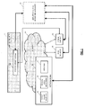
- FIG. 1 presents a QoS Monitoring Manager (QMM) as a system (10) for determining QoS degradations in a MPLS network (30) and also shows the relationships and specific interfaces between the system (10) and existing modules, which are the following ones:
- QMM QoS Monitoring Manager
- FIG. 2 shows a flow diagram of the communication messages exchanged in the network scenario above illustrated in Figure 1 , involving the QMM system (10) which makes use of QoS degradation prevention, detection and restoration procedures as described below.
- Solid lines in Figure 2 refer to mandatory procedures, while dotted lines are used for those procedures which are optional in the system (10).
- This system (10) implements a method for determining QoS degradations which comprises the following main steps:
- the criteria for the alarms management are the following:
- this system (10) is able to manage them: attending first those which locate impairments quicker, the system (10) is later able to determine which nodes/links and LSPs/services are affected, and is able to correlate the rest of the alarms so they do not need to be considered. It is important to mention that having a higher detection or location time does not prevent alarms from the slowest modules to appear in the whole network scenario, since every tool can monitor different parameters and is more adequate for different purposes.
- Figures 3-6 extend the basic workflow previously described in Figure 2 and include the interactions that take place among the QMM system (10) and the existing modules in several use cases.
- Two main categories of use cases can be defined: those cases, shown in FIGs. 3-5 , in which the QMM system (10) operation is reactive, i.e., it reacts after the QoS degradation has happened; and those such as the one shown in Figure 6 , in which the QMM system (10) is proactive, i.e., it reacts trying to avoid the QoS degradation before it happens.
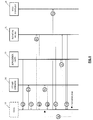
- Figure 3 shows the specific workflow for a use case in which the alarm is received from the application layer (20), which means that the customer is being aware of the QoS degradation, so the QMM system (10) operation must be reactive to quickly solve the alarm situation.
- the system (10) receives an alarm (a1) from the application layer (20), and consults (b1) the DataBase (36) to obtain (c1) the network path that is being used by application layer (20) for the given service to which the alarm refers to. Then, the system (10) checks internally other potential alarms which may have been received from network nodes (31) by the QMM system (10) along that specific path.
- the system (10) finds any (which should normally be the case), it groups them according to the specific network segment or node affected (if already identified by the other alarms), and jumps into a step (f1) of consulting again the DataBase (36) for information on all the services that might be potentially affected by such events.
- the subsequent step (g1) is the DataBase (36) giving a Response.
- the QMM system (10) requests (d1) the MPLS OAM (34) mechanisms in the network nodes (31) to carry out specific on-demand operations to locate the fault, depending on the type of alarm received from the application layer (20). The complete definition of which operations are associated to which alarms is out of the scope of the invention.
- the MPLS OAM (34) tools could be those that measure the packet delay along the path.
- the tests carried out by the MPLS OAM (34) tools should be first related with the end-to-end path. In case the result (e1) from the MPLS OAM (34) mechanisms operations to locate the fault is adequate, then the system (10) declares that potential problems can be located within the customer premises. Resolution of such problems is also out of the scope of the invention.
- segment by segment testing is done to locate the specific segment or node affected by degradation.
- Tests performed by the MPLS OAM (34), are triggered and controlled by the QMM system (10), which is the one having the information of the segments.
- the QMM system (10 is the one having the information of the segments.
- the system (10) continues with steps (f1) and (g1) of query and answer respectively to/from the DataBase (36), equivalent to those ones described above.
- the system (10) has a clear vision on what services can be affected by the different degradations, so it triggers (h1) MPLS signaling (35) to initiate the protection/restoration mechanisms for each of those services affected by the alarm. Results of the restoration procedures are provided in step (i1).
- the QMM system (10) needs to check the correct operation of all the restored services, so it triggers (j1) on-demand monitoring mechanisms either at the application layer (20), if possible depending on availability of such tools at the different customers premises, or via MPLS OAM (31), which is always available. Results from testing are provided in step (k1). In case some of the results from testing are unsatisfactory, the system (10) consults again (l1) the DataBase (36) for alternative paths for those services, and repeats (in a loop) the execution of steps from (h1) to (k1) for those alternative paths. It has to be noted that many networks have their own automatic restoration procedures, for example, when links are cut.
- the system (10) is aware of such situation in steps (c1) or (g1), since the DataBase (36) already provides the information that one or several specific services have been automatically restored to a backup path.
- the QMM system (10) duties on such event grant that other services, possibly not able to automatically being recovered, are not affected either. The operation for them is equivalent to what has already been described in the use case of Figure 3 .
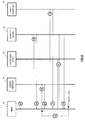
- FIG 4 shows the specific workflow of another use case in which the QMM system (10) operation is reactive to an alarm received from the physical layer monitoring (33) tools.
- the QMM system (10) receives an alarm (a2) from the physical layer monitoring (33) tools, and does not need to execute the location operations, i.e., avoiding steps from (b) to (e) in the basic flow of Figure 2 , since these tools already provide such information. Therefore, system (10) goes directly to the gathering of other potential alarms referring to the same segment (coming from network nodes (31) with lower alarm priority), and jump into step (f2) to consult the DataBase (36) for information on all the services that might be potentially affected by this specific event. Response from DataBase (36) is given in step (g2).
- the QMM system (10) has a clear vision on what services can be affected by the degradation, so it triggers (h2) MPLS signaling (35) mechanisms to initiate the protection mechanisms for each of those services. Results of the restoration procedures are provided in step (i2). Finally, the QMM system (10) needs to check the correct operation of all the restored services, so it triggers on-demand monitoring mechanisms (j2) either at the application layer (20), if possible depending on availability of such tools at the different customers premises, or via MPLS OAM (31), which is always available. Results from testing are provided in step (k2).
- the QMM system (10) consults again (l2) the DataBase (36) for alternative paths for those services and executes in a loop, if required, steps from (h2) to (k2) for those alternative paths.
- the QMM system (10) can only be aware of such situation in step (g2); for those cases, the system (10) duties are restricted to those services which cannot be automatically recovered. The operation for them is equivalent to what has already been described in the use case of Figure 4 .
- Figure 5 shows a specific workflow of another use case in which the QMM system (10) operation is reactive to an alarm received from the MPLS OAM (34) tools.
- monitoring can be done at different MPLS levels, and between different pairs of MPLS network nodes (31), even if they are not directly connected.
- the operation of the system (10) depends on how this monitoring is done. For alarms coming from tools executed between network nodes (31) which are directly connected, the operation is similar to use cases shown in Figure 4 , where an alarm is received from the physical layer monitoring (33) or the passive traffic analyzer (32), since no location procedures need to be run, but with the following differences:
- Figure 6 shows the QMM system (10) able to react to potential degradations in a proactive way, i.e., even before they happen.
- the main event from which the QMM system (10) can protect the network (30) is traffic congestion.
- Three network operation zones can be distinguished
- the QMM system 10 initially uses the passive traffic analyzer (32) for passive monitoring, thus not consuming network bandwidth to detect "potentially conflictive" situations.
- SNMP protocol for example, can monitor network bandwidth until a certain threshold is surpassed.
- MPLS OAM (34) tools within the network segment which is "potentially conflictive".
- This type of monitoring is to detect and locate "critical" situations very quickly: since the network segment to monitor has been very much reduced, the bandwidth consumption problem is strictly controlled, and the amount of monitoring packets that can be injected can be high enough to ensure the adequate performance.
- Passive monitoring tools of the passive traffic analyzer (32) are continuously measuring the network traffic, and in case they measure bandwidths that surpass the specified threshold for "potentially conflictive" situations, they generate an alarm (a4) to the QMM system (10), as shown in the flow chart of Figure 6 .
- the specific segment is already located by the passive tool, so the QMM system (10) is able to directly request (d4) the MPLS OAM (34) tools to execute continuous high-bandwidth-demanding tests over that segment. It may happen that the threshold towards "critical” situations is never surpassed. Then, eventually, the passive traffic analyzer (32) that is still running can detect that the network segment has gone back to the "correct operation” zone and announces this to the QMM system (10), which in turn stops the active monitoring of the MPLS OAM (34) tools.
- the MPLS OAM (34) tools announces it (e4) to the QMM system (10), which in turn starts a similar procedure, steps from (f4) to (l4) to the one in other use cases, for example in the use case of receiving alarms from MPLS OAM (34) shown in Figure 5 .
- the QMM system (10) needs not to modify the path for all the services traversing the "critical” segment, but just for enough of them as to go back to the "potentially conflictive" situation (eventually notified via a new alarm coming from the MPLS OAM (34) tools), and ii) the paths modification must be done without any traffic loss.
- the QMM system (10) modifies and verifies one service's path at a time, until it receives an alarm from the MPLS OAM (34) tools stating that the situation has turned back into “potentially conflictive”.
- the candidate service for migration selection criterion is out of the scope of this invention.
- the passive traffic analyzer (32) can determine "correct operation”, and then it is possible to migrate back the services to the original paths, once again without any traffic loss.
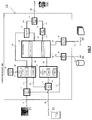
- Figure 7 depicts the architecture of the proposed Quality of Service Monitoring Manager QMM system (10), including the different modules and interfaces.
- the system (10) needs not be built on a single physical machine; it is possible to distribute the different functionalities over different physical elements, in particular over the MPLS network nodes themselves, with the only requirement of implementing the required interfaces' functionalities. For implementation and correct operation, it is required at least one processor and Ethernet connectivity towards all the required external modules. However, multiple processors are recommended for higher performance. Further description of the different modules and the different, internal and external, interfaces is provided below, according to a possible embodiment of the invention.
- CM constitutes the brain and intelligence of the system (10) and is in charge of coordinating all the executed operations in the different possible use cases, as described before.
- CM constitutes the brain and intelligence of the system (10) and is in charge of coordinating all the executed operations in the different possible use cases, as described before.
- Service Layer, Network Layer, DDBB, Operator COMM modules (101, 102, 103, 105) and Signaling Scheduler (104) module interface external systems.
- the common objective of such modules (101, 102, 103, 104, 105) is to hide from the QMM processing modules the particular details of potentially different implementations of the external interfaces, unifying the communications towards inner modules.
- the System Database (36) can be implemented using different technologies, and thus, DDBB - DBCOMM interface (203) can present different technical implementations, all giving support to the same set of requirements.
- the DDBB COMM module (103) is then in charge of translating the different format messages, providing unified messages over CM - DBCOMM interface (212).
- Service Layer COMM (101), SLCOMM: interfaces the Service Support System (21) to receive alarms or request active testing at the service layer. Received alarms are then sent to the Alarm Management & Correlation module (106), while active tests triggering is done at the Active Monitoring Trigger module (107).
- Network Layer COMM (102), NLCOMM: interfaces the network nodes to receive alarms from different external systems: i) Physical Layer Monitoring (33), ii) Passive Traffic Analyzer (32) and/or iii) MPLS OAM (34). It may also request active MPLS OAM testing or an on-demand passive poll. Received alarms are sent to the Alarm Management & Correlation module (106), module which also triggers the passive on-demand poll. On the other hand, active tests triggering is done at the Active Monitoring Trigger module (107).
- Alarm Management & Correlation module (106), module which also triggers the passive on-demand poll.
- active tests triggering is done at the Active Monitoring Trigger module (107).
- DDBB COMM (103) DBCOMM interfaces the System Database (36) to receive information regarding the network/service status or regarding new paths over which to provision restored services. This information is requested by the Computation Module (100). The Computation Module (100) can also populate, via this module, the System Database (36) with network/service status changes that the QMM system (10) has detected.
- SS interfaces the MPLS Signaling (35) functionalities available in the network to permit restoration procedures, at the request of the Computation Module (100).
- These functionalities in the simplest implementation, could be accessed via a management network using the network nodes Command Line Interface or CLI. Alternative more sophisticated solutions providing equivalent features are valid.
- Operator COMM (105), OCOMM: provides an interface for the operator (700) to configure both the priority levels of the different alarms that could be received and the thresholds between the operation zones for use case in which the QMM system (10) operates proactively, values which are stored in the Configuration module (109). Its external interface permits the operator (700) to consult information about the occurred alarms and performed actions as well, information coming from the Logs Storage module (110). The rest of the processing internal modules of the QMM system (10) are:
- AMT Active Monitoring Trigger
- this module is in charge of prompting the active tests available in the external systems, in particular, in the Service Support System (21) for tests at the service layer or using the MPLS OAM (34) tools of the network nodes. Communication with the former is made across the Service Layer COMM module (101), while the Network Layer COMM module (102) permits communication with the latter. The execution of external active tests is requested by the Computation Module (100), and results are provided back by the Active Monitoring Trigger (107).
- Synchronization Clock (108), SC it provides the clock for the synchronization of the correlation procedures carried out at the Alarm Management & Correlation module (106).
- CONF it stores the configuration parameters provided by the operator for the priority values to be given to each of the potentially to be received alarms, and for the two thresholds separating the operation zones in use case in which the QMM system (10) operates proactively. First set of parameters is then forwarded to the Alarm Management & Correlation module (106), while the second is forwarded to the Computation Module (100).
- Logs Storage (110), LS: it stores information about occurred alarms and executed associated corrective actions, information which is provided by the Computation Module (100), prior to its presentation to the operator (700), via the Operator COMM module (105).
- Both interfaces share the same procedure: To forward all the alarms received from external monitoring systems towards the Alarm Management & Correlation module (106).
- the format of the messages differs depending on the specific external module generating the alarm, since in each procedure different types of information are available; in particular, whenever the "fault location" information is available, it should be added to the message body.
- the response message from the Alarm Management & Correlation module (106) is an acknowledgement of reception.
- the NLCOMM - AMC Interface (207) also permits another procedure: The Alarm Management & Correlation module (106) to request a certain type of external passive measurement at the network nodes.
- the request message must include: i) the network node/interface where the measurement should be done, ii) the type of measurement to be done, e.g., consumed bandwidth, and iii) for how long or how many repetitions should be done.
- the input for the last parameter could be in the form of "until a certain threshold is surpassed", as required by use case in which the QMM system (10) operates proactively.
- the response message from the Network Layer COMM module (102) provides the result of the requested measurement.
- the Active Monitoring Trigger module (107) to request a certain type of external active measurement, either by the Service Support System (21) or by the MPLS OAM (34) mechanisms of the network nodes (31).
- the request message must include: i) the specific service - in case of service layer monitoring - or the network segment/node/interface - in case of network layer monitoring - to be tested, ii) the type of measurement to be done, e.g., experienced delay, and iii) for how long or how many repetitions should be done.
- the input for the last parameter can be in the form of "until a certain threshold is surpassed", as required by use case in which the QMM system (10) operates proactively.
- the response messages from the Service Layer and Network layer COMM modules (101, 102) provide the result of the requested measurement.
- the Alarm Management & Correlation module (106) to send sets of correlated alarms to the Computation Module (100).
- the format of these messages differs depending on the specific external module generating the alarm, as stated also for the SLCOMM - AMC and NLCOMM - AMC Interfaces (206, 207).
- the response message from the Computation Module (100) is an acknowledgement of reception.
- the Computation Module (100) to request a certain type of external passive measurement to the Alarm Management & Correlation module (106).
- the format of the request and response messages should match a scheme equivalent to the second procedure in the NLCOMM - AMC Interface (207).
- CM - AMT Interface (211): It permits one procedure.
- the Computation Module (100) to request a certain type of external active measurement to the Active Monitoring Trigger module (107).
- the request message includes the same information as for the SLCOMM - AMT (208) or NLCOMM - AMC (209) Interfaces, with an additional field to specify the external element to carry out the measurement, i.e., if it needs to be handled by the application layer probes or the MPLS OAM (34) mechanisms.
- the response message from the Active Monitoring Trigger module (107) provides the result of the requested measurement.
- the Computation Module (100) to request a restoration operation to the Signaling Scheduler (104).
- the request message must include: i) the specific service(s) which need to be restored, and ii) the network path over which these services should be restored. It must be noted, therefore, that services can be grouped into a single request when they share the same new path. Services affected by the same fault, but restored over different paths, generate different requests in this interface.
- Response from the SS module (104) includes the result of the restoration operation (successfully accomplished or not, and the reason in the latter case).
- OCOMM - CONF Interface (214): It permits two procedures:
- the Operator COMM module (105) to store in the Configuration module (109) the priority values set by the operator (700) for the different external alarms available in the monitoring system.
- the message includes an unrepeated integer value per each of the types of alarm, and the response is an acknowledgement of reception.
- the Operator COMM module (105) to store in the Configuration module (109) the two threshold values separating the three operation zones defined in use case in which the QMM system (10) operates proactively.
- the message includes two values between 0 and 100, corresponding to the link bandwidth usage values that separate such zones.
- the response is an acknowledgement of reception.
- the Configuration Module (109) to store in the Alarm Management & Correlation module (106) the priority values of the different types of alarms that the system can receive, values which are configurable by the operator (700). In other words, this is a sort of relay of the first procedure in the OCOMM - CONF Interface (214). Response is an acknowledgement of reception.
- the Configuration Module (109) stores in the Computation Module (100) the threshold values that define the operation zones (use case in which the QMM system (10) operates proactively), values which are configurable by the operator (700).
- the message includes two values, separating the "correct” and “potentially conflictive” zones on one side, and the latter with the "critical” zone on the other. Again, it is a sort of relay, in this case of the second procedure in the OCOMM - CONF Interface (214). Response is an acknowledgement of reception.
- the Computation Module (100) to store in the Logs Storage module (110) all the information required by operators (700), as stated in the OCOMM - LS Interface (217). Response is an acknowledgement of reception.
- the Synchronization Clock (108) to provide the timing for the correlation procedures in the Alarm Management & Correlation module (106). This is a continuous clock signal with no specific messages being interchanged.
- External interfaces are interfaces permitting communication with external systems that may present many different kinds of interface implementations. This way, the internal specific procedures of the QMM system (10) are hidden of the details of external systems implementation technologies, and share unified message formats. This way, a new interface implementation from an external module just demands modifications in the COMM modules and interfaces of the QMM system (10).
Landscapes
- Engineering & Computer Science (AREA)
- Computer Networks & Wireless Communication (AREA)
- Signal Processing (AREA)
- Data Exchanges In Wide-Area Networks (AREA)
Applications Claiming Priority (1)
| Application Number | Priority Date | Filing Date | Title |
|---|---|---|---|
| PCT/ES2013/070929 WO2015097318A1 (es) | 2013-12-26 | 2013-12-26 | Procedimiento y sistema para restaurar degradaciones de la qos en redes de mpls |
Publications (2)
| Publication Number | Publication Date |
|---|---|
| EP3089409A1 true EP3089409A1 (de) | 2016-11-02 |
| EP3089409A4 EP3089409A4 (de) | 2017-11-01 |
Family
ID=53477606
Family Applications (1)
| Application Number | Title | Priority Date | Filing Date |
|---|---|---|---|
| EP13900511.0A Withdrawn EP3089409A4 (de) | 2013-12-26 | 2013-12-26 | Verfahren und system zur wiederherstellung von qos-verschlechterungen in mpls-netzwerken |
Country Status (3)
| Country | Link |
|---|---|
| US (1) | US20160308709A1 (de) |
| EP (1) | EP3089409A4 (de) |
| WO (1) | WO2015097318A1 (de) |
Families Citing this family (12)
| Publication number | Priority date | Publication date | Assignee | Title |
|---|---|---|---|---|
| US10404548B2 (en) | 2016-08-29 | 2019-09-03 | Cisco Technology, Inc. | Control of network nodes in computer network systems |
| US11063837B2 (en) * | 2018-11-28 | 2021-07-13 | Cisco Technology, Inc. | Customized network load-balancing using machine learning |
| CN111294226B (zh) * | 2018-12-10 | 2023-05-09 | 华为技术有限公司 | 通信方法和装置 |
| US11552874B1 (en) * | 2019-01-18 | 2023-01-10 | Keysight Technologies, Inc. | Methods, systems and computer readable media for proactive network testing |
| US11627049B2 (en) * | 2019-01-31 | 2023-04-11 | Hewlett Packard Enterprise Development Lp | Failsafe firmware upgrade for cloud-managed devices |
| CN112468311B (zh) * | 2019-09-09 | 2023-01-03 | 中国移动通信有限公司研究院 | 一种保护倒换的方法、节点设备和存储介质 |
| US11671341B2 (en) * | 2019-09-19 | 2023-06-06 | Hughes Network Systems, Llc | Network monitoring method and network monitoring apparatus |
| CN111865670B (zh) * | 2020-07-03 | 2023-06-30 | 宏图智能物流股份有限公司 | 一种仓库网络快速恢复方法以及仓库网络快速恢复服务器 |
| JP7179810B2 (ja) * | 2020-10-27 | 2022-11-29 | 株式会社日立製作所 | クラスタシステム、クラスタシステムのフェイルオーバー制御方法 |
| CN114138348B (zh) * | 2021-11-16 | 2025-03-07 | 中电信数智科技有限公司 | 业务恢复优先级评估方法及设备、存储介质和产品 |
| WO2023168084A1 (en) * | 2022-03-04 | 2023-09-07 | Interdigital Patent Holdings, Inc. | Methods, architectures, apparatuses and systems for enabling wireless reliability and availability in multi-domain deployments |
| CN116170353B (zh) * | 2023-02-01 | 2023-10-24 | 广州通则康威智能科技有限公司 | 一种路由器下挂设备自动测速方法、系统及存储介质 |
Family Cites Families (19)
| Publication number | Priority date | Publication date | Assignee | Title |
|---|---|---|---|---|
| JP2933021B2 (ja) * | 1996-08-20 | 1999-08-09 | 日本電気株式会社 | 通信網障害回復方式 |
| US6865602B1 (en) | 2000-07-24 | 2005-03-08 | Alcatel Canada Inc. | Network management support for OAM functionality and method therefore |
| WO2003005195A2 (en) * | 2001-07-03 | 2003-01-16 | Imagine Broadband Limited | Broadband communications |
| US20060165089A1 (en) * | 2002-05-08 | 2006-07-27 | Joachim Klink | Method for assisting equivalent circuits in mpls networks |
| US8179786B2 (en) * | 2004-05-19 | 2012-05-15 | Mosaid Technologies Incorporated | Dynamic traffic rearrangement and restoration for MPLS networks with differentiated services capabilities |
| US7965620B2 (en) * | 2004-05-25 | 2011-06-21 | Telcordia Licensing Company, Llc | Method, computer product and system for correlating events in a network |
| US7573808B2 (en) * | 2004-08-06 | 2009-08-11 | Fujitsu Limited | Smart resync of data between a network management system and a network element |
| US7822837B1 (en) * | 2004-12-30 | 2010-10-26 | Packeteer, Inc. | Adaptive correlation of service level agreement and network application performance |
| US7551623B1 (en) * | 2005-01-31 | 2009-06-23 | Packeteer, Inc. | Modulation of partition parameters achieving delay-based QoS mechanism |
| JP4758259B2 (ja) * | 2006-01-31 | 2011-08-24 | 株式会社クラウド・スコープ・テクノロジーズ | ネットワーク監視装置及び方法 |
| US7907535B2 (en) * | 2007-11-26 | 2011-03-15 | Alcatel-Lucent Usa Inc. | Anomaly detection and diagnosis using passive monitoring |
| US8284044B2 (en) * | 2008-12-23 | 2012-10-09 | Telefonaktiebolaget Lm Ericsson (Publ) | Poll-based alarm handling system and method |
| US7961599B2 (en) * | 2009-03-03 | 2011-06-14 | Alcatel Lucent | Pseudowire tunnel redundancy |
| US8559336B2 (en) * | 2010-01-29 | 2013-10-15 | Alcatel Lucent | Method and apparatus for hint-based discovery of path supporting infrastructure |
| US9184983B2 (en) * | 2010-08-26 | 2015-11-10 | Futurewei Technologies, Inc. | Cross-stratum optimization protocol |
| WO2012041555A1 (en) * | 2010-09-30 | 2012-04-05 | Telefonaktiebolaget L M Ericsson (Publ) | Method for determining a severity of a network incident |
| US8774010B2 (en) * | 2010-11-02 | 2014-07-08 | Cisco Technology, Inc. | System and method for providing proactive fault monitoring in a network environment |
| US8964563B2 (en) * | 2011-07-08 | 2015-02-24 | Telefonaktiebolaget L M Ericsson (Publ) | Controller driven OAM for OpenFlow |
| EP2795841B1 (de) * | 2011-12-21 | 2021-11-24 | Telefonaktiebolaget LM Ericsson (publ) | Verfahren und anordnung zur fehleranalyse in einem mehrschichtigen netzwerk |
-
2013
- 2013-12-26 EP EP13900511.0A patent/EP3089409A4/de not_active Withdrawn
- 2013-12-26 WO PCT/ES2013/070929 patent/WO2015097318A1/es not_active Ceased
- 2013-12-26 US US15/108,273 patent/US20160308709A1/en not_active Abandoned
Also Published As
| Publication number | Publication date |
|---|---|
| EP3089409A4 (de) | 2017-11-01 |
| WO2015097318A1 (es) | 2015-07-02 |
| US20160308709A1 (en) | 2016-10-20 |
Similar Documents
| Publication | Publication Date | Title |
|---|---|---|
| EP3089409A1 (de) | Verfahren und system zur wiederherstellung von qos-verschlechterungen in mpls-netzwerken | |
| EP4142239A1 (de) | Netzleistungsüberwachung und fehlerverwaltung basierend auf der bewertung des zustands der wan-netzverbindungen | |
| US9237075B2 (en) | Route convergence monitoring and diagnostics | |
| Van Adrichem et al. | Fast recovery in software-defined networks | |
| US9203732B2 (en) | Recovery of traffic in a connection-oriented network | |
| EP3231139B1 (de) | Verfahren und vorrichtung für netzwerktomographie | |
| US8036121B2 (en) | Method of estimating quality degradation on network in communication network system | |
| US20090135727A1 (en) | Anomaly Detection and Diagnosis Using Passive Monitoring | |
| US9571383B2 (en) | Rerouting technique | |
| EP3208978A1 (de) | Dynamische bandbreiteneinstellung in einem paketubertragungsnetzwerk | |
| Troia et al. | Resilience of delay-sensitive services with transport-layer monitoring in SD-WAN | |
| CN102546248B (zh) | 多协议标签交换环境下精确定位故障位置的方法、装置及系统 | |
| EP2129042B1 (de) | Multicast-netzwerksystem, knoten und verfahren zum detektieren eines fehlers einer multicast-netzwerkverbindung | |
| Van et al. | Network troubleshooting: Survey, taxonomy and challenges | |
| Roelens et al. | Performance evaluation of TI-LFA in traffic-engineered segment routing-based networks | |
| US12355613B1 (en) | Application assurance | |
| CN119232621A (zh) | 广域网链路带宽监控 | |
| EP2061186A1 (de) | Verfahren und Vorrichtung zur Bestimmung des Verlaufs einer Verbindung in einem Netzwerk und Kommunikationssystem mit einer solchen Vorrichtung | |
| US9654363B2 (en) | Synthetic loss measurements using session numbers | |
| Kim et al. | OAM and protection mechanisms for MPLS-TP packet transport networks | |
| US20180176125A1 (en) | Systems, apparatuses, and methods for rerouting network traffic | |
| Wang et al. | SRv6 O&M Guide | |
| Kurant et al. | Survey on dependable IP over fiber networks | |
| CN111970153A (zh) | 基于虚拟网关的故障隔离方法、装置及相关设备 | |
| CN114598596A (zh) | 管理隧道的方法、装置及系统 |
Legal Events
| Date | Code | Title | Description |
|---|---|---|---|
| PUAI | Public reference made under article 153(3) epc to a published international application that has entered the european phase |
Free format text: ORIGINAL CODE: 0009012 |
|
| 17P | Request for examination filed |
Effective date: 20160721 |
|
| AK | Designated contracting states |
Kind code of ref document: A1 Designated state(s): AL AT BE BG CH CY CZ DE DK EE ES FI FR GB GR HR HU IE IS IT LI LT LU LV MC MK MT NL NO PL PT RO RS SE SI SK SM TR |
|
| AX | Request for extension of the european patent |
Extension state: BA ME |
|
| DAX | Request for extension of the european patent (deleted) | ||
| A4 | Supplementary search report drawn up and despatched |
Effective date: 20170928 |
|
| RIC1 | Information provided on ipc code assigned before grant |
Ipc: H04L 12/723 20130101AFI20170922BHEP Ipc: H04L 12/24 20060101ALI20170922BHEP Ipc: H04L 12/707 20130101ALI20170922BHEP Ipc: H04L 12/851 20130101ALI20170922BHEP |
|
| STAA | Information on the status of an ep patent application or granted ep patent |
Free format text: STATUS: REQUEST FOR EXAMINATION WAS MADE |
|
| STAA | Information on the status of an ep patent application or granted ep patent |
Free format text: STATUS: THE APPLICATION IS DEEMED TO BE WITHDRAWN |
|
| 18D | Application deemed to be withdrawn |
Effective date: 20180501 |