EP3089423B1 - Procédé d'émission de signal ethernet, procédé de planification, et dispositif et système associés - Google Patents
Procédé d'émission de signal ethernet, procédé de planification, et dispositif et système associés Download PDFInfo
- Publication number
- EP3089423B1 EP3089423B1 EP14879032.2A EP14879032A EP3089423B1 EP 3089423 B1 EP3089423 B1 EP 3089423B1 EP 14879032 A EP14879032 A EP 14879032A EP 3089423 B1 EP3089423 B1 EP 3089423B1
- Authority
- EP
- European Patent Office
- Prior art keywords
- signal
- network device
- pcsl
- information
- monitoring information
- Prior art date
- Legal status (The legal status is an assumption and is not a legal conclusion. Google has not performed a legal analysis and makes no representation as to the accuracy of the status listed.)
- Not-in-force
Links
- 238000000034 method Methods 0.000 title claims description 69
- 230000008054 signal transmission Effects 0.000 title claims description 22
- 238000012544 monitoring process Methods 0.000 claims description 222
- 230000001172 regenerating effect Effects 0.000 claims description 9
- 238000003780 insertion Methods 0.000 claims description 7
- 230000037431 insertion Effects 0.000 claims description 7
- 239000003550 marker Substances 0.000 claims description 6
- 230000003287 optical effect Effects 0.000 description 84
- 238000006243 chemical reaction Methods 0.000 description 55
- 238000012545 processing Methods 0.000 description 51
- 230000010287 polarization Effects 0.000 description 25
- 238000010586 diagram Methods 0.000 description 20
- 230000005540 biological transmission Effects 0.000 description 11
- 238000004891 communication Methods 0.000 description 8
- 238000005516 engineering process Methods 0.000 description 6
- 238000012546 transfer Methods 0.000 description 5
- 230000009286 beneficial effect Effects 0.000 description 4
- 238000011069 regeneration method Methods 0.000 description 4
- 102100035309 GRIP and coiled-coil domain-containing protein 1 Human genes 0.000 description 3
- 102100028617 GRIP and coiled-coil domain-containing protein 2 Human genes 0.000 description 3
- 101001024398 Homo sapiens GRIP and coiled-coil domain-containing protein 1 Proteins 0.000 description 3
- 101001058870 Homo sapiens GRIP and coiled-coil domain-containing protein 2 Proteins 0.000 description 3
- 238000012937 correction Methods 0.000 description 3
- 238000005538 encapsulation Methods 0.000 description 3
- 238000011084 recovery Methods 0.000 description 3
- 101100143815 Saccharomyces cerevisiae (strain ATCC 204508 / S288c) RPL3 gene Proteins 0.000 description 2
- 230000000295 complement effect Effects 0.000 description 2
- 230000007547 defect Effects 0.000 description 2
- 239000002699 waste material Substances 0.000 description 2
- 238000012790 confirmation Methods 0.000 description 1
- 238000011161 development Methods 0.000 description 1
- 238000000605 extraction Methods 0.000 description 1
- 238000012423 maintenance Methods 0.000 description 1
- 238000007726 management method Methods 0.000 description 1
- 238000013507 mapping Methods 0.000 description 1
- 238000012986 modification Methods 0.000 description 1
- 230000004048 modification Effects 0.000 description 1
- 230000011664 signaling Effects 0.000 description 1
- 238000012360 testing method Methods 0.000 description 1
Images




Classifications
-
- H—ELECTRICITY
- H04—ELECTRIC COMMUNICATION TECHNIQUE
- H04L—TRANSMISSION OF DIGITAL INFORMATION, e.g. TELEGRAPHIC COMMUNICATION
- H04L43/00—Arrangements for monitoring or testing data switching networks
- H04L43/08—Monitoring or testing based on specific metrics, e.g. QoS, energy consumption or environmental parameters
- H04L43/0805—Monitoring or testing based on specific metrics, e.g. QoS, energy consumption or environmental parameters by checking availability
- H04L43/0811—Monitoring or testing based on specific metrics, e.g. QoS, energy consumption or environmental parameters by checking availability by checking connectivity
-
- H—ELECTRICITY
- H04—ELECTRIC COMMUNICATION TECHNIQUE
- H04L—TRANSMISSION OF DIGITAL INFORMATION, e.g. TELEGRAPHIC COMMUNICATION
- H04L1/00—Arrangements for detecting or preventing errors in the information received
- H04L1/004—Arrangements for detecting or preventing errors in the information received by using forward error control
- H04L1/0056—Systems characterized by the type of code used
- H04L1/0057—Block codes
-
- H—ELECTRICITY
- H04—ELECTRIC COMMUNICATION TECHNIQUE
- H04J—MULTIPLEX COMMUNICATION
- H04J3/00—Time-division multiplex systems
- H04J3/16—Time-division multiplex systems in which the time allocation to individual channels within a transmission cycle is variable, e.g. to accommodate varying complexity of signals, to vary number of channels transmitted
- H04J3/1605—Fixed allocated frame structures
- H04J3/1652—Optical Transport Network [OTN]
-
- H—ELECTRICITY
- H04—ELECTRIC COMMUNICATION TECHNIQUE
- H04L—TRANSMISSION OF DIGITAL INFORMATION, e.g. TELEGRAPHIC COMMUNICATION
- H04L1/00—Arrangements for detecting or preventing errors in the information received
- H04L1/0001—Systems modifying transmission characteristics according to link quality, e.g. power backoff
- H04L1/0006—Systems modifying transmission characteristics according to link quality, e.g. power backoff by adapting the transmission format
-
- H—ELECTRICITY
- H04—ELECTRIC COMMUNICATION TECHNIQUE
- H04L—TRANSMISSION OF DIGITAL INFORMATION, e.g. TELEGRAPHIC COMMUNICATION
- H04L47/00—Traffic control in data switching networks
- H04L47/70—Admission control; Resource allocation
- H04L47/82—Miscellaneous aspects
- H04L47/822—Collecting or measuring resource availability data
-
- H—ELECTRICITY
- H04—ELECTRIC COMMUNICATION TECHNIQUE
- H04L—TRANSMISSION OF DIGITAL INFORMATION, e.g. TELEGRAPHIC COMMUNICATION
- H04L69/00—Network arrangements, protocols or services independent of the application payload and not provided for in the other groups of this subclass
- H04L69/12—Protocol engines
Definitions
- Embodiments of the present invention relate to network technologies, and in particular, to an Ethernet signal transport method and scheduling method, and an apparatus and a system thereof.
- Multi-Lane, MLD for short a multi-lane structure is generally used.
- an optical transport network (Optical Transport Network) is used to effectively transport an Ethernet signal.
- a network device A transmits an Ethernet signal to a network device B by using an optical transport network
- a wavelength division multiplexing (Wavelength Division Multiplexing, WDM for short) device or an optical transport network device is required to encapsulate the Ethernet signal into an optical channel payload unit (Optical channel Payload Unit, OPU for short), and then sequentially encapsulate an optical channel data unit (Optical channel Data Unit, ODU for short) overhead, an optical channel transport unit (Optical channel Transport Unit, OTU for short) overhead, and the like.
- WDM Wavelength Division Multiplexing
- a transport path is monitored by using an OTU overhead and an ODU overhead, which requires a dedicated device to encapsulate a client signal multiple times and requires additional processing such as encapsulation and mapping.
- OTU overhead and an ODU overhead which requires a dedicated device to encapsulate a client signal multiple times and requires additional processing such as encapsulation and mapping.
- US 2005/0102419 A1 provides a method for utilizing inter packet gaps to create an extended link monitoring channel in a physical layer transceiver for a 10 Gb/s Ethernet link.
- Embodiments of the present invention provide an Ethernet signal transport method and scheduling method, and an apparatus and a system thereof, so as to resolve a problem in the prior art that a processing process of Ethernet signal transport is complicated and costs of processing resources used in Ethernet signal transport are relatively high.
- an embodiment of the present invention provides an Ethernet signal transport method, including:
- the path monitoring information is carried by using an overhead bit block, where the overhead bit block includes at least one bit block.
- the path monitoring information includes a regenerator section RS overhead, where the RS overhead is used to monitor a status of signal transmission between signal regenerating terminals.
- the path monitoring information further includes a multiplex section MS overhead, where the MS overhead is used to monitor a status of signal transmission between two multiplexers.
- the monitoring information applied for by using the additional request information includes any one of the following: trail trace identifier TTI information, path type fault location FTFL information, payload structure identifier PSI information, and broadband adjustment-related information.
- the inserting, by a first network device, path monitoring information into a position that is a preset bit length away from an AM in a PCSL of an Ethernet signal includes:
- the method before the sending, by the first network device to at least one second network device, a signal bearing the PCSL into which the path monitoring information is inserted, the method further includes:
- the performing, by the first network device, electrical-to-optical conversion on the signal bearing the PCSL into which the path monitoring information is inserted, to generate an optical signal includes: performing, by the first network device by using on-off-keying OOK modulation, polarization multiplexing phase modulation, or polarization multiplexing phase amplitude modulation, electrical-to-optical conversion on the signal bearing the PCSL into which the path monitoring information is inserted, to generate the optical signal.
- the method before the performing, by the first network device, electrical-to-optical conversion on the signal bearing the PCSL into which the path monitoring information is inserted, to generate an optical signal, the method further includes: performing, by the first network device, forward error correction FEC coding on the signal bearing the PCSL into which the path monitoring information is inserted.
- an Ethernet signal scheduling method including:
- the method before the performing, by a first network device, PCSL switching on M electrical signals, the method further includes: performing, by the first network device, PCSL synchronization on the M electrical signals, so that PSCLs of the M electrical signals have a same clock frequency and AM phase.
- the performing, by the first network device, PCSL synchronization on the M electrical signals includes: performing, by the first network device, PCSL synchronization by inserting or deleting an idle bit block in the M electrical signals.
- the method before the performing, by a first network device, PCSL switching on M electrical signals, the method further includes: performing, by the first network device, PCSL rate adjustment on the M electrical signals, so that the PSCLs of the M electrical signals have a same nominal bit rate.
- the method before the performing, by a first network device, PCSL switching on M electrical signals, the method further includes:
- the method before the performing, by a first network device, PCSL switching on M electrical signals, the method further includes:
- the method before the sending, by the first network device, the N Ethernet signals to at least one second network device, the method further includes:
- the performing, by the first network device, electrical-to-optical conversion on the N Ethernet signals to generate an optical signal includes: performing, by the first network device by using OOK modulation, polarization multiplexing phase modulation, or polarization multiplexing phase amplitude modulation, electrical-to-optical conversion on the N Ethernet signals, to generate the optical signal.
- an Ethernet signal transport apparatus including:
- the path monitoring information is carried by using an overhead bit block, where the overhead bit block includes at least one bit block.
- the path monitoring information includes a regenerator section RS overhead, where the RS overhead is used to monitor a status of signal transmission between signal regenerating terminals.
- the path monitoring information further includes a multiplex section MS overhead, where the MS overhead is used to monitor a status of signal transmission between two multiplexers.
- the path monitoring information further includes additional request information, where the additional request information is used to apply to the at least one second network device for monitoring information of a corresponding type.
- the monitoring information applied for by using the additional request information includes any one of the following: trail trace identifier TTI information, path type fault location FTFL information, payload structure identifier PSI information, and broadband adjustment-related information.
- the insertion module is specifically configured to: insert the path monitoring information into a position that is the preset bit length away from each AM in the PCSL of the Ethernet signal, and perform scrambling on the path monitoring information.
- the sending module is further configured to: before the sending module sends the signal bearing the PCSL into which the path monitoring information is inserted to the at least one second network device, perform electrical-to-optical conversion on the signal bearing the PCSL into which the path monitoring information is inserted, to generate an optical signal; and send the optical signal generated by means of electrical-to-optical conversion to the at least one second network device.
- the sending module is further configured to: before converting the signal bearing the PCSL into which the path monitoring information is inserted, to generate the optical signal, perform FEC coding on the signal bearing the PCSL into which the path monitoring information is inserted.
- an embodiment of the present invention further provides an Ethernet signal scheduling apparatus, including:
- the apparatus further includes: an alignment module, configured to: before the switching module performs PCSL switching on the M electrical signals, perform PCSL synchronization on the M electrical signals, so that PSCLs of the M electrical signals have a same clock frequency and AM phase.
- the alignment module is further configured to: before the switching module performs PCSL switching on the M electrical signals, perform PCSL rate adjustment on the M electrical signals, so that the PSCLs of the M electrical signals have a same nominal bit rate.
- the apparatus further includes:
- the apparatus further includes:
- the sending module is further configured to: before the sending module sends the N Ethernet signals to the at least one second network device, perform electrical-to-optical conversion on the N Ethernet signals to generate an optical signal; and send the optical signal generated by means of electrical-to-optical conversion to the at least one second network device.
- an embodiment of the present invention further provides an Ethernet signal transport apparatus, including a receiver, a transmitter, and a processor, where the processor is configured to insert path monitoring information into a position that is a preset bit length away from an AM in a PCSL of an Ethernet signal; and the transmitter is configured to send, to at least one second network device, a signal bearing the PCSL into which the path monitoring information is inserted.
- the path monitoring information is carried by using an overhead bit block, where the overhead bit block includes at least one bit block.
- the path monitoring information includes a regenerator section RS overhead, where the RS overhead is used to monitor a status of signal transmission between signal regenerating terminals.
- the path monitoring information further includes a multiplex section MS overhead, where the MS overhead is used to monitor a status of signal transmission between two multiplexers.
- the path monitoring information further includes additional request information, where the additional request information is used to apply to the at least one second network device for monitoring information of a corresponding type.
- the monitoring information applied for by using the additional request information includes any one of the following: trail trace identifier TTI information, path type fault location FTFL information, payload structure identifier PSI information, and broadband adjustment-related information.
- the processor is configured to: insert the path monitoring information into a position that is the preset bit length away from each AM in the PCSL of the Ethernet signal, and perform scrambling on the path monitoring information.
- the transmitter is further configured to: before the transmitter sends the signal bearing the PCSL into which the path monitoring information is inserted to the at least one second network device, perform electrical-to-optical conversion on the signal bearing the PCSL into which the path monitoring information is inserted, to generate an optical signal; and send the optical signal generated by means of electrical-to-optical conversion to the at least one second network device.
- the transmitter is further configured to: before performing electrical-to-optical conversion on the signal bearing the PCSL into which the path monitoring information is inserted, to generate the optical signal, perform FEC coding on the signal bearing the PCSL into which the path monitoring information is inserted.
- an embodiment of the present invention further provides an Ethernet signal scheduling apparatus, including a receiver, a transmitter, and a processor, where the processor is configured to perform PCSL switching on M electrical signals to generate N Ethernet signals or N client signals, where M ⁇ 1, N ⁇ 1, and M and N cannot be 1 at the same time; and the transmitter is configured to send the N Ethernet signals to at least one second network device; or send the N client signals to at least one first MAC processing device.
- an Ethernet signal scheduling apparatus including a receiver, a transmitter, and a processor, where the processor is configured to perform PCSL switching on M electrical signals to generate N Ethernet signals or N client signals, where M ⁇ 1, N ⁇ 1, and M and N cannot be 1 at the same time; and the transmitter is configured to send the N Ethernet signals to at least one second network device; or send the N client signals to at least one first MAC processing device.
- the processor is further configured to: before performing PCSL switching on the M electrical signals, perform PCSL synchronization on the M electrical signals, so that PSCLs of the M electrical signals have a same clock frequency and AM phase.
- the processor is further configured to perform PCSL synchronization by inserting or deleting an idle bit block in the M electrical signals.
- the processor is further configured to: before performing PCSL switching on the M electrical signals, perform PCSL rate adjustment on the M electrical signals, so that the PSCLs of the M electrical signals have a same nominal bit rate.
- the processor is further configured to: before performing PCSL switching on the M electrical signals, lock AMs of the M electrical signals, so as to acquire PCSL sequence information of the M electrical signals; and perform PCSL switching according to the PCSL sequence information and switching configuration information.
- the receiver is configured to: before PCSL switching is performed on the M electrical signals, receive an optical signal sent by at least one another network device, and perform optical-to-electrical conversion on the optical signal sent by the at least one another network device, to generate the M electrical signals; or the receiver is configured to: receive a client signal sent by at least one second MAC processing device, and perform bit block coding on the client signal sent by the at least one second MAC processing device, to generate the M electrical signals.
- the transmitter is further configured to: before the transmitter sends the N Ethernet signals to the at least one second network device, perform electrical-to-optical conversion on the N Ethernet signals to generate an optical signal; and send the optical signal generated by means of electrical-to-optical conversion to the at least one second network device.
- an embodiment of the present invention further provides a network system, including at least the Ethernet signal transport apparatus described in any one possible implementation manner of the foregoing third aspect or the Ethernet signal transport apparatus described in any one possible implementation manner of the foregoing fifth aspect.
- an embodiment of the present invention further provides a network system, including at least the Ethernet signal scheduling apparatus described in any one possible implementation manner of the foregoing fourth aspect or the Ethernet signal scheduling apparatus described in any one possible implementation manner of the foregoing sixth aspect.
- an embodiment of the present invention further provides a network system, including at least the Ethernet signal transport apparatus described in any one possible implementation manner of the third aspect and the Ethernet signal scheduling apparatus described in any one possible implementation manner of the fifth aspect; or the Ethernet signal transport apparatus described in any one possible implementation manner of the fourth aspect and the Ethernet signal scheduling apparatus described in any one possible implementation manner of the sixth aspect.
- a first network device inserts path monitoring information into a PCSL of an Ethernet signal, or directly performs PCSL switching, which reduces multiple times of encapsulation and decapsulation of the Ethernet signal, and corresponding processing, thereby reducing processing resource costs of Ethernet signal transport, and avoiding waste of processing resources.
- Ethernet signal processing is mainly classified into data link layer (Data Link) processing and physical layer (Physical) processing. It should be noted that solutions involved in the embodiments of the present invention are explained and described mainly with respect to physical layer processing of an Ethernet signal.
- FIG. 1 is a flowchart of an Ethernet signal transport method according to Embodiment 1 of the present invention.
- the method in this embodiment is applicable to a case in which an Ethernet signal is transported from one network device to one or more network devices.
- the method is executed by a first network device, where the apparatus is generally implemented by means of hardware and/or software. As shown in FIG. 1 , the method in this embodiment includes the following steps:
- An Ethernet signal of an MLD structure includes multiple physical coding sublayer lanes (Physical Coding Sublayer Lane, PCSL for short). For example, a 40G Ethernet signal has 4 PCSLs (0 to 3), and a 100G Ethernet signal has 20 PCSLs (0 to 19).
- Information about each PCSL includes a service data block, a control block, and an alignment marker (Alignment Marker, AM for short) that are borne by the PCSL.
- the AM is an identifier inserted into each PCSL after block distribution is performed at a physical coding sublayer (Physical Coding Sublayer, PCS for short), where the identifier is used to mark a sequence number of the PCSL.
- each PCSL of an Ethernet signal bears, in a form of a bit block, corresponding information such as service data and control information.
- a quantity of bits in a bit block in each PCSL may be a fixed quantity of bits, for example, 66bit.
- a bit quantity and structure of an AM available in a PCSL of an Ethernet signal may keep consistent with those of another bit block in the PCSL of the Ethernet signal, where the bit quantity may also be 66bit.
- a sequence number of the PCSL in which the AM is located is carried by using the 66-bit information.
- Each PCSL includes at least one AM.
- the PCSL includes more than two AMs
- different AMs identify a same PCSL sequence number, and any two adjacent AMs of the different AMs are spaced by a fixed quantity of bits or a fixed quantity of bit blocks, for example, may be spaced by 16383 66-bit bit blocks.
- the 66-bit bit block includes a 64-bit information bit and a 2-bit synchronization header (Sync Header) bit.
- the 66-bit bit block carries data information or a control packet by using the 64-bit information bit, and identifies, by using the 2-bit synchronization header bit, whether the current bit block is a data bit block or a control bit block. For example, it may be that a synchronization header 10 indicates that the bit block is a control bit block; accordingly, a synchronization header 01 indicates that the bit block is a data bit block.
- the path monitoring information may contain multi-level multi-type path monitoring information. Inserting path monitoring information into an Ethernet signal may be: bearing the path monitoring information in multiple bit blocks, and evenly distributing these bit blocks bearing the path monitoring information between any two AMs of the Ethernet signal. For example, it is assumed that the path monitoring information is borne in seven 66-bit bit blocks. In an Ethernet signal, any two AMs are spaced by a fixed quantity of bits. For example, any two adjacent AMs are spaced by 16383 66-bit bit blocks. Therefore, a preset bit length between a bit block of the 7 bit blocks bearing the path monitoring information and an adjacent AM may be 2047 bit blocks, and any two adjacent bit blocks bearing the path monitoring information are spaced by 2047 bit blocks. Therefore, in step 101, the preset bit length away from the AM may also be a preset bit block length. Certainly, the insertion may not be performed according to a bit block, and may be performed according to a preset bit length.
- An Ethernet signal includes multiple PCSLs, and each PCSL includes an AM used to mark a corresponding sequence number of the PCSL. Therefore, the sending, by the first network device to at least one second network device, a signal bearing the PCSL into which the path monitoring information is inserted may be: sending, according to a sequence number carried by the AM in the signal of the PCSL into which the path monitoring information is inserted and according to a preset configuration, the signal bearing the PCSL into which the path monitoring information is inserted to the at least one second network device at a granularity of a PCSL.
- the first network device and the second network device are located on different signal transport nodes, and may be routers or switches.
- the sending, according to a preset configuration, the signal bearing the PCSL into which the path monitoring information is inserted to the at least one second network device at a granularity of a PCSL contains at least two application scenarios.
- a first application scenario is an application scenario in which one Ethernet signal corresponds to one Ethernet link. This is also a mainstream application scenario of a current Ethernet network.
- step 101 in the solution of the foregoing embodiment specifically includes: selecting, by the first network device, one PCSL in the Ethernet signal according to a preset configuration; and inserting the path monitoring information into a position that is the preset bit length away from an AM in the PCSL.
- the signal bearing the PCSL into which the path monitoring information is inserted is the Ethernet signal bearing the PCSL into which the path monitoring information is inserted.
- Step 102 specifically includes: sending, by the first network device, the Ethernet signal bearing the PCSL into which the path monitoring information is inserted to one second network device.
- a second application scenario is an application scenario in which one Ethernet signal corresponds to at least two Ethernet links.
- This application scenario is applicable to transport in a flexible Ethernet (Flexible or Sliceable Ethernet, FlexEth for short).
- the FlexEth mainly means that one Ethernet port may be configured as multiple virtual Ethernet ports, so as to split one Ethernet link into multiple Ethernet links (also referred to as sub Ethernet links in the following) by using the configured multiple virtual Ethernet ports. These sub Ethernet links may be connected to different routers or switches. In this way, one FlexEth signal may correspond to at least two Ethernet links.
- step 101 in the solution of the foregoing embodiment specifically includes: selecting, by the first network device, at least two PCSLs in the Ethernet signal according to a preset configuration; and inserting the path monitoring information into a position that is the preset bit length away from an AM in each PCSL of the at least two PCSLs.
- the at least two PCSLs need to cover all Ethernet links. That is, at least one PCSL needs to be selected for each Ethernet link for inserting the path monitoring information. For example, one PCSL may be selected for each Ethernet link for inserting the path monitoring information. A transport status of each Ethernet link is monitored by using the path monitoring information inserted into the selected PCSL.
- step 102 in the solution of the foregoing embodiment may specifically include: sending respectively, by the first network device, signals bearing the at least two PCSLs into which the path monitoring information is inserted to at least two second network devices according to preset attribution configurations of Ethernet links corresponding to the at least two PCSLs.
- the signal sent to any one network device of the at least two second network devices may be a signal bearing a part of PCSLs in the Ethernet signal in step 101 (in at least one PCSL in each part of PCSLs, the path monitoring information is inserted into a position that is the preset bit length away from an AM).
- a first network device directly inserts path monitoring information into a PCSL of an Ethernet signal, which reduces multiple times of encapsulation and decapsulation of the Ethernet signal, and corresponding processing, thereby reducing processing resource costs of Ethernet signal transport, and avoiding waste of processing resources.
- this embodiment of the present invention further provides an Ethernet signal transport method.
- the path monitoring information is carried by using an overhead bit block, where the overhead bit block includes at least one bit block.
- the carrying the path monitoring information by using an overhead (Overhead, OH for short) bit block may be carrying the path monitoring information by using information bits of the overhead bit block.
- a bit quantity and structure of the OH bit block may keep consistent with those of another bit block such as a data bit block and a control bit block in the Ethernet signal. That is, the OH bit block may also be 66bit, including a 64-bit overhead information bit and a 2it synchronization header bit.
- the 64-bit overhead information bit may be 8 octets, Octet0 to Octet7.
- the path monitoring information includes a regenerator section RS overhead, where the RS overhead is used to monitor a status of signal transmission between signal regenerating terminals.
- the carrying the path monitoring information by using an OH bit block may be carrying overhead information having a relatively strict requirement for transmission time by using the OH bit block.
- the overhead information having a relatively strict for transmission time may be regenerator section (Regenerator section, RS for short) overhead information.
- the signal generating terminal refers to a terminal that can perform electro-regeneration or electric processing on a signal.
- the first network device inserts path monitoring information into a position that is a preset bit length away from an AM in a PCSL of an Ethernet signal. In general, information can be inserted only by means of electric processing. Therefore, the first network device needs to perform electric processing on a signal, and belongs to a signal regenerating terminal.
- the first network device sends, to at least one second network device, a signal bearing the PCSL into which the path monitoring information is inserted. If the at least one second network device needs to perform electro-regeneration or electric processing on the signal bearing the PCSL into which the path monitoring information is inserted, the at least one second network device also belongs to a signal regenerating terminal. In this case, what is monitored by the RS overhead is a status of signal transmission between the first network device and the at least one second network device, including signal transmission statuses of the first network device and the at least one second network device.
- the at least one second network device does not perform electro-regeneration or electric processing on the signal bearing the PCSL into which the path monitoring information is inserted, but only transmits the signal bearing the PCSL into which the path monitoring information is inserted to at least one third network device, for example, only directly sends, at an optical layer, the signal bearing the PCSL into which the path monitoring information is inserted to the at least one third network device, the at least one third network device performs electro-regeneration or electric processing on the signal bearing the PCSL into which the path monitoring information is inserted.
- what is monitored by the RS overhead is a status of signal transmission between the first network device and the at least one third network device, certainly including signal transmission statuses of the first network device and the at least one third network device.
- the RS overhead information may include reserved overhead information of an RS, general communication channel (General Communication Channel0, GCC0 for short) information of the RS, and section monitoring information of the RS.
- the section monitoring information of the RS includes: backward defect indication (Backward Defect Indication, BDI for short) information, incoming alignment error (Incoming Alignment Error, IAE for short) information, backward error indication (Backward Error Indication, BEI for short) information, or backward incoming alignment error (Backward Incoming Alignment Error, BIAE for short) information.
- the path monitoring information in the foregoing solution further includes a multiplex section MS overhead, where the MS overhead is used to monitor a status of signal transmission between two multiplexers.
- the foregoing overhead information having a relatively strict for transmission time further includes multiplex section (Multiplex Section, MS for short) overhead information.
- the multiplexer refers to a terminal that multiplexes different transmitted signals on one link for transmission or demultiplexes a signal from a same link as multiple signals, for example, sends signal to multiple processing modules by using multiple links.
- an Ethernet signal received by the first network device is signals sent by multiple network devices
- the signals sent by the multiple network devices are multiplexed on one link and are transmitted to at least one second network device
- a signal received by the second network device is demultiplexed as multiple signals.
- both the first network device and the at least one second network device are multiplexers. What is monitored by the MS overhead is a status of signal transmission between the first network device and the at least one second network device, and signal transmission statuses of the first network device and the at least one second network device.
- the MS overhead information may include monitoring information of an MS and at least one piece of GCC information of the MS, for example, GCC1 and GCC2 information.
- the monitoring information of the MS includes: status field (Status, STAT for short) information, BDI information, BEI information, and bit interleaved parity (Bit Interleaved Parity, BIP for short) information.
- the path monitoring information in the foregoing solution further includes additional request information, where the additional request information is used to apply to the at least one second network device for monitoring information of a corresponding type.
- the monitoring information applied for by using the additional request information includes any one of the following: trail trace identifier TTI information, path type fault location FTFL information, payload structure identifier PSI information, and broadband adjustment-related information.
- overhead information having a relatively strict requirement for time is carried by using the OH bit block, and overhead information having a relatively loose requirement for time may be applied for from a second network device by using the additional request information.
- the monitoring information applied for by using the additional request message includes: trail trace identifier (Trail Trace Identifier, TTI for short) information, path type fault location (Fault Type and Fault Location, FTFL for short) information, payload structure identifier (Payload Structure Identifier, PSI for short) information, and broadband adjustment-related information.
- the additional request message includes a type (Type, TYP for short). Corresponding information may be applied for from the second network device according to different request information indicated by different configurations of the TYP.
- the TTI information includes regenerator section TTI information, multiplex section TTI information, and tandem connection monitoring (Tandem Connection Monitoring, TCM for short) TTI information.
- the TYP may be 5bit, corresponding to 32 different monitoring information request messages.
- the TYP is expressed by a binary-coded 00001, that is, a hexadecimally-coded 01, monitoring information currently requested by using the additional request message is regenerator section TTI information; if the TYP is expressed by a binary-coded 00010, that is, a hexadecimally-coded 02, monitoring information currently requested by using the additional request message is multiplex section TTI information; if the TYP is expressed by a binary-coded 00011, that is, a hexadecimally-coded 03, monitoring information currently requested by using the additional request message is tandem connection monitoring (Tandem Connection Monitoring, TCM for short) TTI information; if the TYP is expressed by a binary-coded 00100, that is, a hexadecimally-coded 04, monitoring information currently requested by using the additional request message is FTFL information; if the TYP is expressed by a binary-coded 00101, that is, a hexadecimally-code
- the path monitoring information further includes: information about three TCMs, namely TCM1 to TCM3, automatic protection switching (Automatic Protection Switching, APS for short), protection communication (Protection Communication Channel, PCC for short) channel information, and the like.
- the information may be included in the RS overhead information.
- the carrying the path monitoring information by using an OH bit block may be: using 3 bit blocks OH1 to OH3 to carry the path monitoring information having a strict requirement for time; and carrying the additional request information in the 3 bit blocks to transfer the path monitoring information having a relatively loose requirement for time.
- FIG. 2 is a schematic structural diagram of an Ethernet signal into which path monitoring information is inserted according to Embodiment 2 of the present invention.
- Inserting path monitoring information into a PCSL of an Ethernet signal is actually inserting the path monitoring information into any two adjacent AMs in the PCSL of the Ethernet signal averagely.
- any two AMs in a PCSL of an Ethernet signal are spaced by a fixed quantity of bits, that is, 16383 bit blocks, it is determined, according to path monitoring information to be inserted, that is, path monitoring information having a strict requirement for time, that 3 OH bit blocks need to be inserted. If 3 OH bit blocks are inserted, adjacent OH bit blocks carrying the path monitoring information are spaced by 4095 bit blocks, and an OH bit block and an adjacent AM are also spaced by 4095 bit blocks.
- one field is selected from OH1 to OH3 to carry additional request information, where the field may be located in any one or more overhead blocks of OH1 to OH3.
- Monitoring information of a corresponding type, which is applied for by using the additional request information is generally sent by the at least one second network device (in some cases, when the first network device and the at least one second network device need to make a handshake for confirmation, the first network device also sends some monitoring information of the corresponding type which is applied for by using the additional request information). Therefore, the monitoring information may be carried by using a reserved field in OH1 to OH3 of an Ethernet signal that is sent to the first network device by the at least one second network device, or may be carried by using a control block of the Ethernet signal.
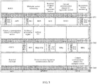
- FIG. 3 is a schematic structural diagram of carrying path monitoring information by using an overhead bit block according to Embodiment 2 of the present invention.
- information bits, namely 8 octets, of OH1 are used to carry monitoring information of a regenerator section, general communication channel information GCC0 of the regenerator section, reserved overhead information of the regenerator section, monitoring information of a multiplex section, and TCM3 information; that information bits of OH2 are used to carry TCM2 information, TCM1 information, latency test information, an additional request message, and a general communication channel GCC1 of the multiplex section; and that information bits of OH3 are used to carry a general communication channel GCC2 of the multiplex section, protection switching and its communication channel, and reserved overhead information.
- some monitoring information having a relatively loose requirement for time may be transferred in the following manner (as shown in FIG. 3 ):
- a first network device sends a request message to a second network device by using additional request information; and after receiving the first PCSL of an Ethernet signal containing the additional request information, the second network device returns monitoring information of a corresponding type to the first network device, so that the first network device inserts the returned monitoring information into an OH overhead bit block of a subsequent PCSL of the Ethernet signal or into a control bit block of a subsequent PCSL of the Ethernet signal.
- the returned monitoring information may be inserted into the OH overhead bit block of the subsequent PCSL of the Ethernet signal, the returned monitoring information may be inserted into a regenerator section reserved overhead of OH1 and a reserved overhead of OH3 shown in FIG. 3 .
- a regenerator section reserved overhead of OH1 and a reserved overhead of OH3 are used to carry corresponding monitoring information.
- a multi-frame alignment signal Multi-frame Alignment Signal, MFAS for short
- MFAS Multi-frame Alignment Signal
- the returned monitoring information may be inserted into a control block nearest to an OH bit block where the additional request information is located, for example, OH2.
- the control block nearest to OH2 may be a control bit block in 4095 bit clocks between OH3 and OH2, where the 4095 bit blocks include a data bit block and a control bit block.
- the control bit block in the 4095 bit blocks between OH3 and OH2 needs to be used to carry the returned monitoring information.
- the control bit block has a given type value, for example, 0x25.
- the type value is different from a corresponding type value of an existing control bit block carrying control information, setting signaling, or the like corresponding to a data bit block.
- the control bit block has a different structure.
- the control bit block includes: a type of the control bit block, a type TYP of the monitoring information, a transfer status, sequence information, and monitoring information content.
- the type of the control bit block may be a type value, for example, 0x25.
- the type TYP of the monitoring information may be expressed by a binary-coded 00001.
- the transfer status indicates whether a current control bit block is the last bit block carrying the returned monitoring information.
- the sequence information refers to information about a location or sequence of the control bit block in all bit blocks carrying the returned monitoring information. Specific monitoring information may be placed in the monitoring information content.
- the carrying the path monitoring information by using an OH bit block may also be: carrying, by using the OH bit block, all path overhead information required to transfer the Ethernet signal, including overhead information carried by an OTU overhead, an ODU overhead, an OPU overhead, and the like.
- the overhead information carried by the OTU overhead, the ODU overhead, the OPU overhead, and the like is used as an example. All overhead information in this example includes frame alignment overhead information, OTU overhead information, ODU overhead information, and OPU overhead information, a total of 56 octets.
- the frame alignment overhead information includes multi-frame alignment signal (Multi-frame Alignment Signal, MFAS for short) information.
- Existing frame alignment overhead information further includes a frame alignment signal (Frame Alignment Signal, FAS for short).
- the FAS information is carried by using an AM.
- the OTU overhead information includes section monitoring (Section Monitoring, SM for short) information, GCC0 information, and reserved (Reserved, RES for short) information.
- the ODU overhead information includes RES information, tandem connection monitoring active (Tandem Connection Monitoring Active, TCM ACT for short) information, TCM information, path monitoring (Path Monitoring, PM for short) information, fault type and fault location (Fault Type and Fault Location, FTFL for short) information, GCC1 information, GCC2 information, and the like.
- the OPU overhead information includes a payload structure identifier PSI (Payload Structure Identifier, PSI for short) message and RES information.
- PSI Payload Structure Identifier
- FIG. 4 is a schematic structural diagram of another Ethernet signal into which path monitoring information is inserted according to Embodiment 2 of the present invention.
- all path overhead information of the Ethernet signal is carried by using an OH bit block.
- path monitoring information to be inserted that is, all path monitoring information
- the inserted path monitoring information includes information about multiple different formats, which can better ensure reliable transport of an Ethernet signal after the path monitoring information is inserted.
- FIG. 5 is a flowchart of an Ethernet signal transport method according to Embodiment 3 of the present invention.
- the inserting, by a first network device, path monitoring information into a position that is a preset bit length away from an AM in a PCSL of an Ethernet signal in step 101 of the foregoing solution specifically includes: Step 501.
- the first network device inserts the path monitoring information into a position that is the preset bit length away from each AM in the PCSL of the Ethernet signal.
- the Ethernet signal has different PCSLs according to different transmission rates of the Ethernet signal, where each PCSL includes multiple AMs. It should be noted that any two adjacent AMs are spaced by a fixed quantity of bits, for example, 16383 bit blocks, regardless of a quantity of AMs in the PCSL of the Ethernet signal.
- the inserting the path information into a position that is the preset bit length away from each AM refers to inserting the path monitoring information between any two adjacent AMs, which better ensures reliability of the path monitoring information.
- Step 502. The first network device performs scrambling on the path monitoring information.
- Performing scrambling on the inserted path monitoring information improves an anti-interference capability of the path monitoring information, thereby ensuring accuracy of the path monitoring information.
- the method further includes: Step 503.
- the first network device performs electrical-to-optical conversion on the signal bearing the PCSL into which the path monitoring information is inserted, to generate an optical signal.
- the sending, by the first network device to at least one second network device, a signal bearing the PCSL into which the path monitoring information is inserted in step 102 specifically includes: Step 504.
- the first network device sends the optical signal generated by means of electrical-to-optical conversion to the at least one second network device.
- OOK modulation may be used to perform electrical-to-optical conversion on the signal bearing the PCSL into which the path monitoring information is inserted, to generate a short-distance optical signal; accordingly, if the first network device is relatively far away from the second network device, polarization multiplexing phase modulation or polarization multiplexing phase amplitude modulation may be used to perform electrical-to-optical conversion on the signal bearing the PCSL into which the path monitoring information is inserted, to generate a long-distance optical signal.
- the method before the performing, by the first network device, electrical-to-optical conversion on the signal bearing the PCSL into which the path monitoring information is inserted, to generate an optical signal, the method further includes: performing, by the first network device, forward error correction FEC coding on the signal bearing the PCSL into which the path monitoring information is inserted.
- FEC coding may be performed on the signal bearing the PCSL into which the path monitoring information is inserted, so that FEC check is performed during reception, to improve the reception accuracy.
- the solution in this embodiment can ensure reliable transport of the signal bearing the PCSL into which the path monitoring information is inserted.
- FIG. 6 is a flowchart of an Ethernet signal scheduling method according to Embodiment 4 of the present invention. As shown in FIG. 6 , the method specifically includes:
- the solution in this embodiment is mainly for an Ethernet signal of an MLD structure, especially for a FlexEth signal.
- a FlexEth signal because one Ethernet physical port may be configured as multiple logical Ethernet ports, the multiple logical Ethernet ports may be used to send an Ethernet signal or a FlexEth signal to at least one network device, or receive an Ethernet signal or a FlexEth signal that is sent by at least one network device.
- FlexEth signal transmission because multiple logical Ethernet ports need to be configured to send or receive an Ethernet signal or a FlexEth signal, the FlexEth signal needs to be effectively scheduled, so as to improve utilization efficiency of network resources.
- N Ethernet signals are N generalized Ethernet signals, which may be N Ethernet signals or FlexEth signals, including any combination of Ethernet signals and FlexEth signals.
- the foregoing generalized Ethernet is also referred to as an Ethernet, including but not limited to the summary, description of embodiments, accompanying drawings, brief description of accompanying drawings, and claims of the present invention.
- Ethernet in the summary, description of embodiments, accompanying drawings, brief description of accompanying drawings, and claims in the description of the present invention refers to a generalized Ethernet, that is, may be a traditional Ethernet, a FlexEth, or any combination of a traditional Ethernet and a FlexEth.
- the application scenarios may be simply classified into two types: one type is that an Ethernet signal or a FlexEth signal is input and output; and the other type is that an Ethernet signal or a FlexEth signal is input, and a client signal is output, for example, a client signal connected to a MAC processing device or module, or conversely, a client signal is input, and an Ethernet signal or a FlexEth signal is output.
- the M electrical signals in step 601 may also be any combination of Ethernet electrical signals, FlexEth electrical signals, and client signals.
- Performing scheduling on the M electrical signals is also performing PCSL switching on the M electrical signals.
- PCSL switching When PCSL switching is performed, it is allowed that no complete PCSL signal is formed before PCSL switching, for example, no AM is inserted.
- PCSL switching may be classified into three cases: A first case is that an Ethernet signal or a FlexEth signal is input and output. In this case, the M electrical signals contain complete PCSL signals. Therefore, AM locking may be performed first, PCSL switching is then performed on the PCSL signals, and then AM update is performed after switching, where the PCSL signal on which switching is performed may also contain no AM.
- a second case is that an Ethernet signal or a FlexEth signal is input, and a client signal is output.
- PCSL switching is similar to that in the first case, except that AM update is not required after PCSL switching.
- a third case is that a client signal is input, and an Ethernet signal or a FlexEth signal is output. In this case, AM locking is not required before PCSL switching, and an AM is inserted after PCSL switching.
- the N client signals may be sent to the at least one first MAC processing device by using an interface between network devices or modules, for example, a 40G media independent interface (40 Gigabit Media Independent Interface, XLGMII for short) or a 100G media independent interface (100 Gigabit Media Independent Interface, CGMII for short).
- the first MAC processing device herein may include an independent functional module or functional apparatus, for example, any one of an independent chip, a module inside a chip, an independent processing board, and an independent processing device.
- scheduling of an Ethernet signal is implemented by using an ODU switching module.
- the ODU switching module is generally integrated into a WDM device or an optical transport device, and the scheduling is executed by the WDM device or optical transport device. Therefore, the Ethernet signal scheduling method provided in this embodiment does not need to be executed by an additional device, and a network system adopting the Ethernet signal scheduling method described in this embodiment is simple, which can reduce architecture costs of the network system.
- the method further includes: performing, by the first network device, PCSL synchronization on the M electrical signals, so that PSCLs of the M electrical signals have a same clock frequency and AM phase.
- the performing, by the first network device, PCSL synchronization on the M electrical signals specifically includes: performing, by the first network device, PCSL synchronization by inserting or deleting an idle bit block in the M electrical signals.
- the M electrical signals may have PCSLs with different clock frequencies.
- a frequency difference may exist between the different clock frequencies and a clock generated by a clock generating module of the first network device. Therefore, clock compensation may be performed on these different clock frequencies, and then PCSL synchronization is performed on the M electrical signals.
- the clock compensation may be specifically: adjusting all PCSLs in the M electrical signals to a uniform clock frequency by inserting an idle bit block or deleting an idle bit block.
- the method further includes: performing, by the first network device, PCSL rate adjustment on the M electrical signals, so that the PSCLs of the M electrical signals have a same nominal bit rate.
- the performing rate adjustment on the M electrical signals may be: adjusting all different high-rate PCSLs to a low rate, or adjusting all different low-rate PCSLs to a high rate.
- the M electrical signals are two electrical signals, where one is a 400G electrical signal, and the other is a 100G electrical signal.
- the 400G electrical signal includes 20 20Gbps PCSLs, that is, PCSL0 to PCSL19, and the 20 20Gbps PCSLs are configured for two physical lanes (Physical Lane, PL for short), where the two PLs are PL0 and PL1.
- PL0 includes PCSL0, 2, 4, 6, 8, 10, 12, 14, 16, and 18 in sequence
- PL1 includes PCSL1, 3, 5, 7, 9, 11, 13, 15, 17, and 19 in sequence.
- the 400G electrical signal adapted to the two PLs is demultiplexed as four 100G virtual electrical signals, that is, link0 to link3.
- Each 100G virtual electrical signal obtained after demultiplexing includes 20 5G PCSLs.
- the PCSLs of the two PLs are demultiplexed to PCSL0 to PCSL19 of link0 to link3 according to a sequence of PCSL0 to PCSL19.
- PCSL0 in PL0 is allocated to Link0, for example, as PCSL0 of Link0;
- PCSL2 in PL0 is allocated to Link2, for example, as PCSL0 of Link2;
- PCSL4 in PL0 is allocated to Link0, for example, as PCSL1 of Link0;
- PCSL6 in PL0 is allocated to Link2, for example, as PCSL1 of Link2; and the like in sequence.
- the PCSLs in PL1 of the 400G signal are alternately distributed to Link1 and Link3, where a method is similar to the PCSL allocation in PL0, and is not described again.
- Data of a high-rate PCSL can be delivered to multiple low-rate PCSLs by demultiplexing the high-rate PCSL, thereby unifying PCSLs on which switching is required to a low-rate level.
- Adjusting all different low-rate PCSLs to a high rate may be implemented by using a PCSL multiplexing process.
- a specific process is reverse to the foregoing process in the foregoing embodiment.
- Data of a low-rate PCSL is inserted into a high-rate PCSL according to a fixed bit quantity in an interleaved manner, thereby implementing PCSL multiplexing to unify PCSLs on which switching is required to a high-rate level.
- PCSL synchronization may be performed before PCSL rate adjustment, or PCSL synchronization may be performed before PCSL rate adjustment.
- FIG. 7 is a flowchart of an Ethernet signal scheduling method according to Embodiment 5 of the present invention. As shown in FIG. 7 , further, before the performing, by a first network device, PCSL switching on M electrical signals, the method further includes: Step 701. The first network device locks AMs of the M electrical signals, so as to acquire PCSL sequence information of the M electrical signals.
- the performing, by a first network device, PCSL switching on M electrical signals in step 601 of the foregoing solution specifically includes: Step 702.
- the first network device performs PCSL switching according to the PCSL sequence information and preset switching configuration information.
- the M electrical signals may pass through different transmission paths before being transported to the first network device. Therefore, different transmission latencies may be caused, and consequently, PCSL disorder occurs on the M electrical signals received by the first network device.
- the first network device acquires the PCSL sequence information of the M electrical signals by locking AMs of the M electrical signals, where the PCSL sequence information may be specifically represented by sequence number information corresponding to the PCSLs; and may perform re-sorting on the PCSLs of the M electrical signals according to the acquired PCSL sequence information.
- An AM is used to identify a sequence number of a PCSL where the AM is located.
- the AM specifically includes a synchronization header, M0 to M2, bit interleaved parity (Bit Interleaved Parity, BIP for short, BIP 3 ), M4 to M6, and BIP 7 .
- M0 to M2 indicate a code of a sequence number
- M4 to M6 are radix-minus-one complement of M0 to M2
- BIP 7 is radix-minus-one complement of BIP 3 .
- Ethernet signals of different rates correspond to different AM coding rules.
- M0 to M2 are 0x90, 0x76, and 0x47, indicating that a sequence number of a PCSL is 0; for a 100G Ethernet signal, M0 to M2 are 0xC1, 0x68, and 0x21, indicating that a sequence number of a PCSL is 0. Specific codes of other sequence numbers are not listed herein one by one.
- the preset switching configuration information may be specifically a cross-connect relationship of PCSL switching, for example, the y th PCSL in the x th input electrical signal is switched to the j th PCSL in the i th output Ethernet signal or client signal.
- the first network device obtains a PCSL switching configuration according to the PCSL sequence information of the M electrical signals and the preset switching configuration, so as to perform PCSL switching according to the PCSL switching configuration to switch the M electrical signals, to generate N Ethernet signals or client signals.
- the first network device may be connected to at least one another network device, or may be connected to at least one user-side device, for example, connected to the at least one second MAC processing device.
- a signal is transported between the first network device and the at least one another network device by using an optical transport network.
- An optical signal that is sent by the at least one another network device by using the optical transport network and is received by the first network device needs to be converted into the M electrical signals, so that electrical layer processing is performed on the M electrical signals.
- the signal that is sent by the at least one second MAC processing device and is received by the first network device is a client signal sent by a user end, where the client signal includes only corresponding data information and control information.
- the first network device further needs to perform bit block coding on the client signal, which may be: splitting the client signal according to a fixed quantity of bits, for example, 64bit, and adding a 2-bit synchronization header, so as to adapt to a bit format of an electrical signal in an MLD structure.
- the first network device further needs to perform PCSL delivery according to coded bit blocks, so that the M electrical signals are divided into a corresponding quantity of PCSLs according to different transmission rates of the M electrical signals. For example, if one of the M electrical signals is 40G, four PCSLs are generated by means of delivery; if another electrical signal is 100G, 20 PCSLs are generated by means of delivery.
- clock recovery further needs to be performed, which generally occurs in a case in which a received optical signal is a short-distance optical signal
- digital signal extraction further needs to be performed, including frequency mixing, carrier recovery, clock recovery, and the like, which generally occurs in a case in which a received optical signal is a long-distance optical signal.
- the method further includes:
- the performing, by the first network device, electrical-to-optical conversion on the N Ethernet signals to generate an optical signal specifically includes: performing, by the first network device by using OOK modulation, polarization multiplexing phase modulation, or polarization multiplexing phase amplitude modulation, electrical-to-optical conversion on the N Ethernet signals, to generate the optical signal.
- PCSL switching is performed according to PCSL sequence information of M electrical signals and preset switching configuration information, and an independent PCSL re-sorting step is removed, thereby simplifying the solution and reducing costs.
- FIG. 8 is a schematic structural diagram of an Ethernet signal transport apparatus according to Embodiment 6 of the present invention. As shown in FIG. 8 , the transport apparatus 801 specifically includes:
- the path monitoring information is carried by using an overhead bit block, where the overhead bit block includes at least one bit block.
- the path monitoring information includes a regenerator section RS overhead, where the RS overhead is used to monitor a status of signal transmission between signal regenerating terminals.
- the path monitoring information further includes a multiplex section MS overhead, where the MS overhead is used to monitor a status of signal transmission between two multiplexers.
- the path monitoring information further includes additional request information, where the additional request information is used to apply to the at least one second network device for monitoring information of a corresponding type.
- the monitoring information applied for by using the additional request information includes any one of the following: trail trace identifier TTI information, path type fault location FTFL information, payload structure identifier PSI information, and broadband adjustment-related information.
- the insertion module 802 is specifically configured to: insert the path monitoring information into a position that is the preset bit length away from each AM in the PCSL of the Ethernet signal, and perform scrambling on the path monitoring information.
- the sending module 803 is further configured to: before the sending module 803 sends the signal bearing the PCSL into which the path monitoring information is inserted to the at least one second network device, perform electrical-to-optical conversion on the signal bearing the PCSL into which the path monitoring information is inserted, to generate an optical signal; and send the optical signal generated by means of electrical-to-optical conversion to the at least one second network device.
- the sending module 803 is specifically configured to perform, by using on-off-keying OOK modulation, polarization multiplexing phase modulation, or polarization multiplexing phase amplitude modulation, electrical-to-optical conversion on the signal bearing the PCSL into which the path monitoring information is inserted, to generate the optical signal.
- Ethernet signal transport apparatus may be integrated into the first network device described in any one of Embodiments 1 to 5, or may be used as an independent transport apparatus and located between the first network device and the second network device described in Embodiments 4 and 5.
- the Ethernet signal transport apparatus may be applicable to a point-to-point network transport system, or may be applicable to a point-to-multipoint, multipoint-to-point, or multipoint-to-multipoint network transport system.
- the point-to-multipoint, multipoint-to-point, or multipoint-to-multipoint network transport system may be a network transport system located between a metropolitan area convergence layer and a backbone network.
- the Ethernet signal transport apparatus provided in the solution of this embodiment may implement the Ethernet signal transport method in the solution of the foregoing embodiment.
- a specific implementation process and a beneficial effect of the Ethernet signal transport apparatus are similar to those of the foregoing embodiment, and are not described herein again.
- FIG. 9 is a schematic structural diagram of an Ethernet signal scheduling apparatus according to Embodiment 7 of the present invention. As shown in FIG. 9 , the scheduling apparatus 901 specifically includes:
- the scheduling apparatus 901 further includes: an alignment module, configured to: before the switching module 902 performs PCSL switching on the M electrical signals, perform PCSL synchronization on the M electrical signals, so that PSCLs of the M electrical signals have a same clock frequency and AM phase.
- an alignment module configured to: before the switching module 902 performs PCSL switching on the M electrical signals, perform PCSL synchronization on the M electrical signals, so that PSCLs of the M electrical signals have a same clock frequency and AM phase.
- the alignment module is specifically configured to perform PCSL synchronization by inserting or deleting an idle bit block in the M electrical signals.
- the alignment module is further configured to: before the switching module 902 performs PCSL switching on the M electrical signals, perform rate adjustment on the M electrical signals, so that the PSCLs of the M electrical signals have a same nominal bit rate.
- the scheduling apparatus 901 further includes: a locking module, configured to: before the switching module 902 performs PCSL switching on the M electrical signals, lock AMs of the M electrical signals, so as to acquire PCSL sequence information of the M electrical signals.
- a locking module configured to: before the switching module 902 performs PCSL switching on the M electrical signals, lock AMs of the M electrical signals, so as to acquire PCSL sequence information of the M electrical signals.
- the switching module 902 is further configured to perform PCSL switching according to the PCSL sequence information and preset switching configuration information.
- scheduling apparatus 901 further includes:
- the first receiving module is specifically configured to perform, by using OOK demodulation, polarization multiplexing phase demodulation, or polarization multiplexing phase amplitude demodulation, optical-to-electrical conversion on the optical signal sent by the at least one another network device, to generate the M electrical signals.
- the sending module 903 is further configured to: before the sending module 903 sends the N Ethernet signals to the at least one second network device, perform electrical-to-optical conversion on the N Ethernet signals to generate an optical signal; and send the optical signal generated by means of electrical-to-optical conversion to the at least one second network device.
- the sending module 903 is specifically configured to perform, by using OOK modulation, polarization multiplexing phase modulation, or polarization multiplexing phase amplitude modulation, electrical-to-optical conversion on the N Ethernet signals, to generate the optical signal.
- the Ethernet signal scheduling apparatus may be integrated into the first network device described in Embodiments 1 to 3 and Embodiment 6, or may be independently used as a scheduling apparatus and located between the first network device and the second network device or the user-side device such as a MAC processing device, described in Embodiments 1 to 3 and Embodiment 6.
- the Ethernet signal scheduling apparatus may constitute a system together with the Ethernet signal transport apparatus in Embodiment 6, where the system can support effective transport and scheduling of an Ethernet signal, for example, a network transport system located between a metropolitan area convergence layer and a backbone network.
- the Ethernet signal scheduling apparatus may also constitute a system together with another sending module and receiving module instead of the Ethernet signal transport apparatus in Embodiment 6, for interconnection between multiple devices at a site, for example, an internal network system of a data center.
- the Ethernet signal scheduling apparatus provided in the solution of this embodiment may implement the Ethernet signal scheduling method in the solution of the foregoing embodiment.
- a specific implementation process and a beneficial effect of the Ethernet signal scheduling apparatus are similar to those of the foregoing embodiment, and are not described herein again.
- FIG. 10 is a schematic structural diagram of an Ethernet signal transport apparatus according to Embodiment 8 of the present invention.
- the transport apparatus 1001 includes: a receiver 1002, a processor 1003, and a transmitter 1004.
- the processor 1003 is configured to insert path monitoring information into a position that is a preset bit length away from an alignment marker AM in a PCSL of an Ethernet signal.
- the transmitter 1004 is configured to send, to at least one second network device, a signal bearing the PCSL into which the path monitoring information is inserted.
- the path monitoring information is carried by using an overhead bit block, where the overhead bit block includes at least one bit block.
- the path monitoring information includes a regenerator section RS overhead, where the RS overhead is used to monitor a status of signal transmission between signal regenerating terminals.
- the path monitoring information further includes a multiplex section MS overhead, where the MS overhead is used to monitor a status of signal transmission between two multiplexers.
- the path monitoring information further includes additional request information, where the additional request information is used to apply to the at least one second network device for monitoring information of a corresponding type.
- the monitoring information applied for by using the additional request information includes any one of the following: trail trace identifier TTI information, path type fault location FTFL information, payload structure identifier PSI information, and broadband adjustment-related information.
- the processor 1003 is configured to: insert the path monitoring information into a position that is the preset bit length away from each AM in the PCSL of the Ethernet signal, and perform scrambling on the path monitoring information.
- the transmitter 1004 is further configured to: before the transmitter sends the signal bearing the PCSL into which the path monitoring information is inserted to the at least one second network device, perform electrical-to-optical conversion on the signal bearing the PCSL into which the path monitoring information is inserted, to generate an optical signal; and send the optical signal generated by means of electrical-to-optical conversion to the at least one second network device.
- the transmitter 1004 is further configured to perform, by the first network device by using on-off-keying OOK modulation, polarization multiplexing phase modulation, or polarization multiplexing phase amplitude modulation, electrical-to-optical conversion on the signal bearing the PCSL into which the path monitoring information is inserted, to generate the optical signal.
- the transmitter 1004 is further configured to: before performing electrical-to-optical conversion on the signal bearing the PCSL into which the path monitoring information is inserted, to generate the optical signal, perform forward error correction FEC coding on the signal bearing the PCSL into which the path monitoring information is inserted.
- the Ethernet signal transport apparatus provided in this embodiment may be integrated into the first network device described in Embodiments 1 to 7, or may be used as an independent transfer apparatus and located between the first network device and the second network device described in Embodiments 4 and 5, and Embodiment 7.
- the Ethernet signal transport apparatus may be applicable to a point-to-point network transport system, or may be applicable to a point-to-multipoint, multipoint-to-point, or multipoint-to-multipoint network transport system.
- the point-to-multipoint, multipoint-to-point, or multipoint-to-multipoint network transport system may be a network transport system located between a metropolitan area convergence layer and a backbone network.
- the Ethernet signal transport apparatus provided in the solution of this embodiment may implement the Ethernet signal transport method in the solution of the foregoing embodiment.
- a specific implementation process and a beneficial effect of the Ethernet signal transport apparatus are similar to those of the foregoing embodiment, and are not described herein again.
- FIG. 11 is a schematic structural diagram of an Ethernet signal scheduling apparatus according to Embodiment 9 of the present invention.
- the scheduling apparatus 1101 includes: a receiver 1102, a processor 1103, and a transmitter 1104.
- the processor 1103 is configured to perform PCSL switching on M electrical signals to generate N Ethernet signals or N client signals, where M ⁇ 1, N ⁇ 1, and M and N cannot be 1 at the same time.
- the transmitter 1104 is configured to send the N Ethernet signals to at least one second network device; or send the N client signals to at least one first Medium Access Control MAC processing device.
- the processor 1103 is further configured to: before performing PCSL switching on the M electrical signals, perform PCSL synchronization on the M electrical signals, so that PSCLs of the M electrical signals have a same clock frequency and AM phase.
- processor 1103 is further configured to perform PCSL synchronization by inserting or deleting an idle bit block in the M electrical signals.
- the processor 1103 is further configured to: before performing PCSL switching on the M electrical signals, perform rate adjustment on the M electrical signals, so that the PSCLs of the M electrical signals have a same nominal bit rate.
- the processor 1103 is further configured to: before performing PCSL switching on the M electrical signals, lock AMs of the M electrical signals, so as to acquire PCSL sequence information of the M electrical signals; and perform PCSL switching according to the PCSL sequence information and preset switching configuration information.
- the receiver 1102 is configured to: before PCSL switching is performed on the M electrical signals, receive an optical signal sent by at least one another network device, and perform optical-to-electrical conversion on the optical signal sent by the at least one another network device, to generate the M electrical signals; or the receiver 1102 is configured to: receive a client signal sent by at least one second MAC processing device, and perform bit block coding on the client signal sent by the at least one second MAC processing device, to generate the M electrical signals.
- the receiver 1102 is specifically configured to perform, by using OOK demodulation, polarization multiplexing phase demodulation, or polarization multiplexing phase amplitude demodulation, optical-to-electrical conversion on the optical signal sent by the at least one another network device, to generate the M electrical signals.
- the transmitter 1104 is further configured to: before the first network device sends the N Ethernet signals to the at least one second network device, perform electrical-to-optical conversion on the N Ethernet signals to generate an optical signal; and send the optical signal generated by means of electrical-to-optical conversion to the at least one second network device.
- the transmitter 1104 is further configured to perform, by using OOK modulation, polarization multiplexing phase modulation, or polarization multiplexing phase amplitude modulation, electrical-to-optical conversion on the N Ethernet signals, to generate the optical signal.
- Ethernet signal scheduling apparatus may be integrated into the first network device described in Embodiments 1 to 3, Embodiment 6, and Embodiment 8, or may be used as an independent scheduling apparatus and located between the first network device and the second network device described in Embodiments 1 to 3, Embodiment 6, and Embodiment 8.
- the Ethernet signal scheduling apparatus may constitute a system together with the Ethernet signal transport apparatus in Embodiment 6 or Embodiment 8, where the system can support effective transport and scheduling of an Ethernet signal, for example, a network transport system located between a metropolitan area convergence layer and a backbone network.
- the Ethernet signal scheduling apparatus may also constitute a system together with another sending module and receiving module instead of the Ethernet transport apparatus in Embodiment 6 or Embodiment 8, for interconnection between multiple devices at a site, for example, an internal network system of a data center. In this case, only scheduling needs to be performed on an Ethernet signal.
- the Ethernet signal scheduling apparatus provided in the solution of this embodiment may implement the Ethernet signal scheduling method in the solution of the foregoing embodiment.
- a specific implementation process and a beneficial effect of the Ethernet signal scheduling apparatus are similar to those of the foregoing embodiment, and are not described herein again.
- FIG. 12 is a schematic structural diagram of a network system according to Embodiment 10 of the present invention. As shown in FIG. 12 , the network system 1201 includes at least an Ethernet signal transport apparatus 1202.
- the Ethernet signal transport apparatus 1202 may be the foregoing transport apparatus in Embodiment 6 or Embodiment 8.
- FIG. 13 is a schematic structural diagram of a network system according to Embodiment 11 of the present invention. As shown in FIG. 13 , the network system 1301 includes at least an Ethernet signal scheduling apparatus 1302.
- the Ethernet signal scheduling apparatus 1302 may be the scheduling apparatus described in Embodiment 7 or Embodiment 9.
- the network system may be used for interconnection between multiple devices at a site, for example, an internal network system of a data center.
- an Ethernet signal may be effectively scheduled by using the scheduling apparatus.
- FIG. 14 is a schematic structural diagram of a network system according to Embodiment 12 of the present invention. As shown in FIG. 14 , the network system 1401 includes at least an Ethernet signal scheduling apparatus 1402 and an Ethernet signal transport apparatus 1403.
- the Ethernet signal scheduling apparatus 1402 may be the foregoing transport apparatus in Embodiment 6 or Embodiment 8.
- the Ethernet signal transport apparatus 1403 may be the foregoing scheduling apparatus in Embodiment 7 or Embodiment 9.
- the network system may be a point-to-multipoint, multipoint-to-point, or multipoint-to-multipoint network transport system, for example, a network transport system located between a metropolitan area convergence layer and a backbone network.
- reliable transport and effective scheduling of an Ethernet signal may be implemented.
- the program may be stored in a computer-readable storage medium.
- the foregoing storage medium includes: any medium that can store program code, such as a ROM, a RAM, a magnetic disk, or an optical disc.
Landscapes
- Engineering & Computer Science (AREA)
- Computer Networks & Wireless Communication (AREA)
- Signal Processing (AREA)
- Environmental & Geological Engineering (AREA)
- Quality & Reliability (AREA)
- Computer Security & Cryptography (AREA)
- Data Exchanges In Wide-Area Networks (AREA)
- Small-Scale Networks (AREA)
Claims (8)
- Procédé de transport de signal Ethernet, comprenant les étapes suivantes :insertion, par un premier dispositif de réseau, d'informations de surveillance de trajet à une position éloignée d'une longueur en bits préétablie d'un marqueur d'alignement, AM, dans au moins deux voies de sous-couche de codage physique, PCSL, d'un signal Ethernet (S101) ; etenvoi, par le premier dispositif de réseau à au moins deux deuxièmes dispositifs de réseau, de signaux véhiculant les au moins deux PCSL dans lesquelles les informations de surveillance de trajet sont insérées (S102).
- Procédé selon la revendication 1, dans lequel les informations de surveillance de trajet sont acheminées au moyen d'un bloc de bits de service, le bloc de bits de service comprenant au moins un bloc de bits.
- Procédé selon la revendication 1 ou 2, dans lequel les informations de surveillance de trajet comprennent un surdébit de section de régénération, RS, le surdébit de RS servant à surveiller un état d'une transmission de signal entre des terminaux de régénération de signal.
- Procédé selon la revendication 3, dans lequel les informations de surveillance de trajet comprennent en outre un surdébit de section de multiplexage, MS, le surdébit de MS servant à surveiller un état d'une transmission de signal entre deux multiplexeurs.
- Procédé selon l'une quelconque des revendications 1 à 4, dans lequel l'étape d'insertion, par un premier dispositif de réseau, d'informations de surveillance de trajet à une position éloignée d'une longueur en bits préétablie d'un AM dans une PCSL d'un signal Ethernet comprend les étapes suivantes :insertion, par le premier dispositif de réseau, des informations de surveillance de trajet à une position éloignée de la longueur en bits préétablie de chaque AM dans la PCSL du signal Ethernet ; etapplication, par le premier dispositif de réseau, d'un embrouillage aux informations de surveillance de trajet.
- Appareil (S801) de transport de signal Ethernet, comprenant :un module d'insertion (S802), configuré pour insérer des informations de surveillance de trajet à une position éloignée d'une longueur en bits préétablie d'un AM dans au moins deux PCSL d'un signal Ethernet ; etun module d'envoi (S803), configuré pour envoyer, à au moins deux deuxièmes dispositifs de réseau, un signal véhiculant les au moins deux PCSL dans lesquelles les informations de surveillance de trajet sont insérées.
- Appareil (S801) selon la revendication 6, dans lequel les informations de surveillance de trajet comprennent en outre des informations de requête supplémentaires, les informations de requête supplémentaires servant à solliciter à l'au moins un deuxième dispositif de réseau des informations de surveillance d'un type correspondant, les informations de surveillance sollicitées au moyen des informations de requête supplémentaires comprenant un élément quelconque dans le groupe constitué par : des informations d'identifiant de trace de chemin, TTI, des informations de type de trajet et de localisation de défaut, FTFL, des informations d'identifiant de structure de charge utile, PSI, et des informations relatives à une adaptation en large bande.
- Appareil (S801) selon l'une quelconque des revendications 6 ou 7, dans lequel le module d'insertion est plus particulièrement configuré pour : insérer les informations de surveillance de trajet à une position éloignée de la longueur en bits préétablie de chaque AM dans la PCSL du signal Ethernet, et appliquer un embrouillage aux informations de surveillance de trajet.
Applications Claiming Priority (1)
| Application Number | Priority Date | Filing Date | Title |
|---|---|---|---|
| PCT/CN2014/070593 WO2015106386A1 (fr) | 2014-01-14 | 2014-01-14 | Procédé d'émission de signal ethernet, procédé de planification, et dispositif et système associés |
Publications (3)
| Publication Number | Publication Date |
|---|---|
| EP3089423A1 EP3089423A1 (fr) | 2016-11-02 |
| EP3089423A4 EP3089423A4 (fr) | 2017-03-29 |
| EP3089423B1 true EP3089423B1 (fr) | 2018-07-18 |
Family
ID=53542264
Family Applications (1)
| Application Number | Title | Priority Date | Filing Date |
|---|---|---|---|
| EP14879032.2A Not-in-force EP3089423B1 (fr) | 2014-01-14 | 2014-01-14 | Procédé d'émission de signal ethernet, procédé de planification, et dispositif et système associés |
Country Status (5)
| Country | Link |
|---|---|
| US (2) | US10462028B2 (fr) |
| EP (1) | EP3089423B1 (fr) |
| KR (2) | KR101881561B1 (fr) |
| CN (2) | CN107682217B (fr) |
| WO (1) | WO2015106386A1 (fr) |
Families Citing this family (33)
| Publication number | Priority date | Publication date | Assignee | Title |
|---|---|---|---|---|
| US10097480B2 (en) | 2015-09-29 | 2018-10-09 | Ciena Corporation | Time transfer systems and methods over flexible ethernet |
| CN107786320B (zh) * | 2016-08-25 | 2021-06-22 | 华为技术有限公司 | 一种发送和接收业务的方法、装置和网络系统 |
| WO2018065039A1 (fr) * | 2016-10-05 | 2018-04-12 | Huawei Technologies Duesseldorf Gmbh | Dispositif et procédé de communication de multiples flux à efficacité spectrale |
| EP3809665B1 (fr) | 2016-10-24 | 2022-10-12 | Huawei Technologies Co., Ltd. | Dispositif de transmission de données dans un ethernet flexible |
| CN108075903B (zh) | 2016-11-15 | 2020-04-21 | 华为技术有限公司 | 用于建立灵活以太网群组的方法和设备 |
| CN113300876B (zh) * | 2016-12-26 | 2022-09-02 | 华为技术有限公司 | Dcn报文处理方法、网络设备和网络系统 |
| CN109075992B (zh) | 2017-03-08 | 2022-03-01 | 默升科技集团有限公司 | 以太网链路扩展方法和设备 |
| JP6950215B2 (ja) * | 2017-03-21 | 2021-10-13 | 富士通株式会社 | 通信装置及び信号中継方法 |
| CN116418647A (zh) * | 2017-03-21 | 2023-07-11 | 中兴通讯股份有限公司 | 网络管理信息的收发方法、装置和设备 |
| CN113316037B (zh) * | 2017-05-02 | 2022-08-09 | 华为技术有限公司 | 一种业务承载的方法、设备和系统 |
| CN108965157B (zh) * | 2017-05-19 | 2020-08-07 | 华为技术有限公司 | 数据传输方法、装置、设备及系统 |
| CN114726479B (zh) * | 2017-07-18 | 2024-12-27 | 华为技术有限公司 | 一种检测块发送和接收的方法、网络设备和系统 |
| US10212260B2 (en) * | 2017-07-19 | 2019-02-19 | Credo Technology Group Limited | SerDes architecture with a hidden backchannel protocol |
| CN109428840B (zh) * | 2017-08-31 | 2022-05-06 | 华为技术有限公司 | 一种通信方法、设备及存储介质 |
| CN110048798B (zh) * | 2018-01-15 | 2021-09-24 | 深圳市中兴微电子技术有限公司 | 一种数据传输方法及装置 |
| CN108419259B (zh) * | 2018-02-11 | 2021-05-28 | 烽火通信科技股份有限公司 | 基于保留开销字段实现灵活以太网保护倒换的方法及系统 |
| CN109495341B (zh) * | 2018-11-12 | 2021-01-15 | 苏州裕太微电子有限公司 | 一种以太网的分时发送线对信息及线对检测方法 |
| US10942888B2 (en) * | 2019-03-26 | 2021-03-09 | Raytheon Company | Data transferring without a network interface configuration |
| CN112039638B (zh) | 2019-06-04 | 2025-02-25 | 华为技术有限公司 | 指示故障状态的方法和装置 |
| US11916661B2 (en) | 2019-06-27 | 2024-02-27 | Ciena Corporation | Distributing timing over metro transport networking |
| CN112291123B (zh) * | 2019-07-24 | 2023-04-21 | 中兴通讯股份有限公司 | 基于邻居协商实现网络对通的方法及装置 |
| US11438300B2 (en) | 2019-10-16 | 2022-09-06 | Raytheon Company | Alternate control channel for network protocol stack |
| US11412073B2 (en) | 2019-10-16 | 2022-08-09 | Raytheon Company | Alternate control channel for network protocol stack |
| US11349704B2 (en) | 2020-06-17 | 2022-05-31 | Credo Technology Group Limited | Physical layer interface with redundant data paths |
| US11646959B2 (en) | 2020-07-20 | 2023-05-09 | Credo Technology Group Limited | Active ethernet cable with broadcasting and multiplexing for data path redundancy |
| US11356302B1 (en) | 2020-11-30 | 2022-06-07 | Credo Technology Group Limited | Equalizer training during link speed negotiation |
| CN114584333A (zh) * | 2020-12-02 | 2022-06-03 | 华为技术有限公司 | 一种数据传输方法、通信装置及通信系统 |
| WO2022125769A1 (fr) | 2020-12-10 | 2022-06-16 | Ciena Corporation | Canal de messagerie dans une trame tns optique cohérente |
| US11552722B2 (en) | 2020-12-10 | 2023-01-10 | Ciena Corporation | Precision time protocol using a coherent optical DSP frame |
| CN115037287B (zh) | 2021-03-05 | 2023-07-28 | 默升科技集团有限公司 | 扩频时钟转换器 |
| US11424968B1 (en) | 2021-06-10 | 2022-08-23 | Credo Technology Group Limited | Retimer training during link speed negotiation and link training |
| CN113660033B (zh) * | 2021-08-31 | 2022-09-16 | 烽火通信科技股份有限公司 | 一种高速接口瞬断快速恢复的方法及系统 |
| US12438567B2 (en) | 2023-10-23 | 2025-10-07 | Credo Technology Group Limited | SerDes method and device having a protocol-agnostic in-band management channel |
Family Cites Families (28)
| Publication number | Priority date | Publication date | Assignee | Title |
|---|---|---|---|---|
| US20050058149A1 (en) * | 1998-08-19 | 2005-03-17 | Howe Wayne Richard | Time-scheduled and time-reservation packet switching |
| US6944163B2 (en) * | 2000-02-09 | 2005-09-13 | Nortel Networks Limited | 10 Gigabit ethernet mappings for a common LAN/WAN PMD interface with a simple universal physical medium dependent interface |
| WO2005018167A1 (fr) * | 2003-08-19 | 2005-02-24 | Fujitsu Limited | Dispositif de transmission et systeme de transmission |
| US7949782B2 (en) * | 2003-11-06 | 2011-05-24 | Qualcomm Incorporated | Extended link monitoring channel for 10 Gb/s Ethernet |
| CN1791057B (zh) * | 2004-12-15 | 2011-06-15 | 华为技术有限公司 | 在光传送网中传输数据业务的方法及其装置 |
| CN1816035B (zh) * | 2005-02-02 | 2010-07-07 | 华为技术有限公司 | 基于数据通信网的主备传输路径实现方法 |
| JP4317860B2 (ja) * | 2006-08-30 | 2009-08-19 | 株式会社日立コミュニケーションテクノロジー | 光集線装置および光加入者装置 |
| US8401387B2 (en) * | 2007-08-30 | 2013-03-19 | Calix, Inc. | Optical network interface devices and methods |
| CN101447975B (zh) | 2007-11-26 | 2013-12-04 | 华为技术有限公司 | 一种处理以太网物理层oam开销的方法及装置 |
| CN101447675B (zh) | 2008-12-12 | 2012-06-27 | 中国电力科学研究院 | 一种抑制次同步谐振的方法 |
| US7835401B2 (en) * | 2009-02-18 | 2010-11-16 | Applied Micro Circuits Corporation | System and method for inverse multiplexing using transcoding and frame alignment markers |
| US8346091B2 (en) * | 2009-04-29 | 2013-01-01 | Andrew Llc | Distributed antenna system for wireless network systems |
| US8385374B1 (en) * | 2009-07-15 | 2013-02-26 | Marvell Israel (M.I.S.L.) Ltd. | Multilane communication device |
| US8724660B2 (en) | 2009-12-17 | 2014-05-13 | Electronics And Telecommunications Research Institute | Transmission and reception apparatus for dynamic lane operation in multi-lane based ethernet system, and method of controlling the same |
| CN102196321A (zh) * | 2010-03-05 | 2011-09-21 | 华为技术有限公司 | 100ge数据在光传送网中的传送方法和数据发送装置 |
| CN102195864A (zh) * | 2010-03-18 | 2011-09-21 | 中兴通讯股份有限公司 | Otn设备和otn的带宽调整方法 |
| KR101338702B1 (ko) * | 2010-04-26 | 2013-12-06 | 한국전자통신연구원 | 다중 레인 기반의 고속 이더넷에서 동적 레인 정보를 송수신하는 방법 및 그 장치 |
| CN102255809A (zh) * | 2010-05-18 | 2011-11-23 | 韩国电子通信研究院 | 用于在光传输网络中传送分组的方法和设备 |
| JP5505796B2 (ja) * | 2010-08-03 | 2014-05-28 | 日立金属株式会社 | メディアコンバータ、メディアコンバータのデータ通信方法、及びネットワークシステム |
| KR101717296B1 (ko) * | 2010-12-15 | 2017-03-16 | 한국전자통신연구원 | 선택적 레인 운용을 위한 이더넷 장치 및 방법 |
| US8774623B2 (en) * | 2011-06-30 | 2014-07-08 | Ubiquoss Inc. | Passive optical network system and method for detecting fault in optical network terminal |
| KR20130033059A (ko) * | 2011-09-26 | 2013-04-03 | 한국전자통신연구원 | 동적 레인 운용을 위한 다중 레인 기반 이더넷 장치 및 이더넷 장치의 운용 방법 |
| WO2013185327A1 (fr) * | 2012-06-14 | 2013-12-19 | 华为技术有限公司 | Procédé et appareil pour la transmission et la réception d'un signal client |
| CN102883163B (zh) | 2012-10-08 | 2014-05-28 | 华为技术有限公司 | 用于运动矢量预测的运动矢量列表建立的方法、装置 |
| US9705777B2 (en) * | 2013-02-08 | 2017-07-11 | Macom Connectivity Solutions, Llc | System and method for monitoring encoded signals in a network |
| KR20160098402A (ko) * | 2013-12-16 | 2016-08-18 | 후아웨이 테크놀러지 컴퍼니 리미티드 | 데이터 전송 방법, 장치 및 시스템 |
| US9787429B2 (en) * | 2014-02-07 | 2017-10-10 | Avago Technologies General Ip (Singapore) Pte. Ltd. | Forward error correction (FEC) data transmission system |
| CN104601429B (zh) * | 2014-12-29 | 2019-02-19 | 华为技术有限公司 | 网络控制方法及相关装置 |
-
2014
- 2014-01-14 CN CN201710787982.7A patent/CN107682217B/zh active Active
- 2014-01-14 KR KR1020167021769A patent/KR101881561B1/ko not_active Expired - Fee Related
- 2014-01-14 KR KR1020177021502A patent/KR101881435B1/ko not_active Expired - Fee Related
- 2014-01-14 WO PCT/CN2014/070593 patent/WO2015106386A1/fr not_active Ceased
- 2014-01-14 EP EP14879032.2A patent/EP3089423B1/fr not_active Not-in-force
- 2014-01-14 CN CN201480000208.1A patent/CN105122763B/zh active Active
-
2016
- 2016-07-14 US US15/210,457 patent/US10462028B2/en not_active Expired - Fee Related
-
2019
- 2019-09-18 US US16/575,000 patent/US20200014610A1/en not_active Abandoned
Non-Patent Citations (1)
| Title |
|---|
| None * |
Also Published As
| Publication number | Publication date |
|---|---|
| EP3089423A4 (fr) | 2017-03-29 |
| WO2015106386A1 (fr) | 2015-07-23 |
| CN107682217A (zh) | 2018-02-09 |
| EP3089423A1 (fr) | 2016-11-02 |
| US10462028B2 (en) | 2019-10-29 |
| CN105122763A (zh) | 2015-12-02 |
| KR20170091782A (ko) | 2017-08-09 |
| US20200014610A1 (en) | 2020-01-09 |
| KR101881561B1 (ko) | 2018-07-24 |
| CN107682217B (zh) | 2021-07-27 |
| US20160323164A1 (en) | 2016-11-03 |
| KR20160107263A (ko) | 2016-09-13 |
| CN105122763B (zh) | 2018-08-14 |
| KR101881435B1 (ko) | 2018-07-24 |
Similar Documents
| Publication | Publication Date | Title |
|---|---|---|
| EP3089423B1 (fr) | Procédé d'émission de signal ethernet, procédé de planification, et dispositif et système associés | |
| US11165698B2 (en) | Method for transmitting service signal by using ethernet channel and communications device | |
| US12483334B2 (en) | Method and apparatus for transmitting and receiving client signal in optical transport network | |
| US10250348B2 (en) | Optical transport system and resource optimization method | |
| US10771177B2 (en) | Method for transmitting client signal in optical transport network, and optical transport device | |
| WO2019071369A1 (fr) | Procédé de transmission de données dans un réseau optique et dispositif de réseau optique | |
| US9755756B2 (en) | Transmission device, transmission system, and transmission method | |
| WO2018090856A1 (fr) | Procédé et dispositif de construction de groupe ethernet flexible | |
| EP3454489A1 (fr) | Procédé de transmission de service et premier dispositif de transmission | |
| CN103716108A (zh) | 光传送网的数据映射方法及装置 | |
| AU2010230712A1 (en) | Method and Device for Sending Data and Receiving Service Data | |
| CN120568235B (zh) | 一种otn细颗粒业务的安全传送方法、设备及系统 | |
| CN119921896A (zh) | 一种节能方法以及相关设备 |
Legal Events
| Date | Code | Title | Description |
|---|---|---|---|
| PUAI | Public reference made under article 153(3) epc to a published international application that has entered the european phase |
Free format text: ORIGINAL CODE: 0009012 |
|
| 17P | Request for examination filed |
Effective date: 20160725 |
|
| AK | Designated contracting states |
Kind code of ref document: A1 Designated state(s): AL AT BE BG CH CY CZ DE DK EE ES FI FR GB GR HR HU IE IS IT LI LT LU LV MC MK MT NL NO PL PT RO RS SE SI SK SM TR |
|
| AX | Request for extension of the european patent |
Extension state: BA ME |
|
| RIC1 | Information provided on ipc code assigned before grant |
Ipc: H04J 3/16 20060101ALI20161117BHEP Ipc: H04L 12/911 20130101ALI20161117BHEP Ipc: H04L 12/26 20060101ALI20161117BHEP Ipc: H04L 29/06 20060101AFI20161117BHEP |
|
| A4 | Supplementary search report drawn up and despatched |
Effective date: 20170228 |
|
| RIC1 | Information provided on ipc code assigned before grant |
Ipc: H04J 3/16 20060101ALI20170222BHEP Ipc: H04L 12/911 20130101ALI20170222BHEP Ipc: H04L 29/06 20060101AFI20170222BHEP Ipc: H04L 12/26 20060101ALI20170222BHEP |
|
| DAX | Request for extension of the european patent (deleted) | ||
| RIC1 | Information provided on ipc code assigned before grant |
Ipc: H04L 12/911 20130101ALI20171215BHEP Ipc: H04J 3/16 20060101ALI20171215BHEP Ipc: H04L 12/26 20060101ALI20171215BHEP Ipc: H04L 29/06 20060101AFI20171215BHEP |
|
| GRAP | Despatch of communication of intention to grant a patent |
Free format text: ORIGINAL CODE: EPIDOSNIGR1 |
|
| STAA | Information on the status of an ep patent application or granted ep patent |
Free format text: STATUS: GRANT OF PATENT IS INTENDED |
|
| INTG | Intention to grant announced |
Effective date: 20180205 |
|
| GRAS | Grant fee paid |
Free format text: ORIGINAL CODE: EPIDOSNIGR3 |
|
| GRAA | (expected) grant |
Free format text: ORIGINAL CODE: 0009210 |
|
| STAA | Information on the status of an ep patent application or granted ep patent |
Free format text: STATUS: THE PATENT HAS BEEN GRANTED |
|
| AK | Designated contracting states |
Kind code of ref document: B1 Designated state(s): AL AT BE BG CH CY CZ DE DK EE ES FI FR GB GR HR HU IE IS IT LI LT LU LV MC MK MT NL NO PL PT RO RS SE SI SK SM TR |
|
| REG | Reference to a national code |
Ref country code: GB Ref legal event code: FG4D |
|
| REG | Reference to a national code |
Ref country code: CH Ref legal event code: EP |
|
| REG | Reference to a national code |
Ref country code: IE Ref legal event code: FG4D |
|
| REG | Reference to a national code |
Ref country code: AT Ref legal event code: REF Ref document number: 1020575 Country of ref document: AT Kind code of ref document: T Effective date: 20180815 |
|
| REG | Reference to a national code |
Ref country code: DE Ref legal event code: R096 Ref document number: 602014028930 Country of ref document: DE |
|
| REG | Reference to a national code |
Ref country code: NL Ref legal event code: MP Effective date: 20180718 |
|
| REG | Reference to a national code |
Ref country code: LT Ref legal event code: MG4D |
|
| REG | Reference to a national code |
Ref country code: AT Ref legal event code: MK05 Ref document number: 1020575 Country of ref document: AT Kind code of ref document: T Effective date: 20180718 |
|
| PG25 | Lapsed in a contracting state [announced via postgrant information from national office to epo] |
Ref country code: NL Free format text: LAPSE BECAUSE OF FAILURE TO SUBMIT A TRANSLATION OF THE DESCRIPTION OR TO PAY THE FEE WITHIN THE PRESCRIBED TIME-LIMIT Effective date: 20180718 |
|
| PG25 | Lapsed in a contracting state [announced via postgrant information from national office to epo] |
Ref country code: BG Free format text: LAPSE BECAUSE OF FAILURE TO SUBMIT A TRANSLATION OF THE DESCRIPTION OR TO PAY THE FEE WITHIN THE PRESCRIBED TIME-LIMIT Effective date: 20181018 Ref country code: LT Free format text: LAPSE BECAUSE OF FAILURE TO SUBMIT A TRANSLATION OF THE DESCRIPTION OR TO PAY THE FEE WITHIN THE PRESCRIBED TIME-LIMIT Effective date: 20180718 Ref country code: FI Free format text: LAPSE BECAUSE OF FAILURE TO SUBMIT A TRANSLATION OF THE DESCRIPTION OR TO PAY THE FEE WITHIN THE PRESCRIBED TIME-LIMIT Effective date: 20180718 Ref country code: PL Free format text: LAPSE BECAUSE OF FAILURE TO SUBMIT A TRANSLATION OF THE DESCRIPTION OR TO PAY THE FEE WITHIN THE PRESCRIBED TIME-LIMIT Effective date: 20180718 Ref country code: NO Free format text: LAPSE BECAUSE OF FAILURE TO SUBMIT A TRANSLATION OF THE DESCRIPTION OR TO PAY THE FEE WITHIN THE PRESCRIBED TIME-LIMIT Effective date: 20181018 Ref country code: RS Free format text: LAPSE BECAUSE OF FAILURE TO SUBMIT A TRANSLATION OF THE DESCRIPTION OR TO PAY THE FEE WITHIN THE PRESCRIBED TIME-LIMIT Effective date: 20180718 Ref country code: IS Free format text: LAPSE BECAUSE OF FAILURE TO SUBMIT A TRANSLATION OF THE DESCRIPTION OR TO PAY THE FEE WITHIN THE PRESCRIBED TIME-LIMIT Effective date: 20181118 Ref country code: GR Free format text: LAPSE BECAUSE OF FAILURE TO SUBMIT A TRANSLATION OF THE DESCRIPTION OR TO PAY THE FEE WITHIN THE PRESCRIBED TIME-LIMIT Effective date: 20181019 Ref country code: AT Free format text: LAPSE BECAUSE OF FAILURE TO SUBMIT A TRANSLATION OF THE DESCRIPTION OR TO PAY THE FEE WITHIN THE PRESCRIBED TIME-LIMIT Effective date: 20180718 Ref country code: SE Free format text: LAPSE BECAUSE OF FAILURE TO SUBMIT A TRANSLATION OF THE DESCRIPTION OR TO PAY THE FEE WITHIN THE PRESCRIBED TIME-LIMIT Effective date: 20180718 |
|
| PG25 | Lapsed in a contracting state [announced via postgrant information from national office to epo] |
Ref country code: HR Free format text: LAPSE BECAUSE OF FAILURE TO SUBMIT A TRANSLATION OF THE DESCRIPTION OR TO PAY THE FEE WITHIN THE PRESCRIBED TIME-LIMIT Effective date: 20180718 Ref country code: AL Free format text: LAPSE BECAUSE OF FAILURE TO SUBMIT A TRANSLATION OF THE DESCRIPTION OR TO PAY THE FEE WITHIN THE PRESCRIBED TIME-LIMIT Effective date: 20180718 Ref country code: LV Free format text: LAPSE BECAUSE OF FAILURE TO SUBMIT A TRANSLATION OF THE DESCRIPTION OR TO PAY THE FEE WITHIN THE PRESCRIBED TIME-LIMIT Effective date: 20180718 |
|
| REG | Reference to a national code |
Ref country code: DE Ref legal event code: R097 Ref document number: 602014028930 Country of ref document: DE |
|
| PG25 | Lapsed in a contracting state [announced via postgrant information from national office to epo] |
Ref country code: ES Free format text: LAPSE BECAUSE OF FAILURE TO SUBMIT A TRANSLATION OF THE DESCRIPTION OR TO PAY THE FEE WITHIN THE PRESCRIBED TIME-LIMIT Effective date: 20180718 Ref country code: CZ Free format text: LAPSE BECAUSE OF FAILURE TO SUBMIT A TRANSLATION OF THE DESCRIPTION OR TO PAY THE FEE WITHIN THE PRESCRIBED TIME-LIMIT Effective date: 20180718 Ref country code: RO Free format text: LAPSE BECAUSE OF FAILURE TO SUBMIT A TRANSLATION OF THE DESCRIPTION OR TO PAY THE FEE WITHIN THE PRESCRIBED TIME-LIMIT Effective date: 20180718 Ref country code: EE Free format text: LAPSE BECAUSE OF FAILURE TO SUBMIT A TRANSLATION OF THE DESCRIPTION OR TO PAY THE FEE WITHIN THE PRESCRIBED TIME-LIMIT Effective date: 20180718 |
|
| PLBE | No opposition filed within time limit |
Free format text: ORIGINAL CODE: 0009261 |
|
| STAA | Information on the status of an ep patent application or granted ep patent |
Free format text: STATUS: NO OPPOSITION FILED WITHIN TIME LIMIT |
|
| PG25 | Lapsed in a contracting state [announced via postgrant information from national office to epo] |
Ref country code: SM Free format text: LAPSE BECAUSE OF FAILURE TO SUBMIT A TRANSLATION OF THE DESCRIPTION OR TO PAY THE FEE WITHIN THE PRESCRIBED TIME-LIMIT Effective date: 20180718 Ref country code: DK Free format text: LAPSE BECAUSE OF FAILURE TO SUBMIT A TRANSLATION OF THE DESCRIPTION OR TO PAY THE FEE WITHIN THE PRESCRIBED TIME-LIMIT Effective date: 20180718 Ref country code: SK Free format text: LAPSE BECAUSE OF FAILURE TO SUBMIT A TRANSLATION OF THE DESCRIPTION OR TO PAY THE FEE WITHIN THE PRESCRIBED TIME-LIMIT Effective date: 20180718 |
|
| 26N | No opposition filed |
Effective date: 20190423 |
|
| PG25 | Lapsed in a contracting state [announced via postgrant information from national office to epo] |
Ref country code: SI Free format text: LAPSE BECAUSE OF FAILURE TO SUBMIT A TRANSLATION OF THE DESCRIPTION OR TO PAY THE FEE WITHIN THE PRESCRIBED TIME-LIMIT Effective date: 20180718 Ref country code: MC Free format text: LAPSE BECAUSE OF FAILURE TO SUBMIT A TRANSLATION OF THE DESCRIPTION OR TO PAY THE FEE WITHIN THE PRESCRIBED TIME-LIMIT Effective date: 20180718 |
|
| REG | Reference to a national code |
Ref country code: CH Ref legal event code: PL |
|
| PG25 | Lapsed in a contracting state [announced via postgrant information from national office to epo] |
Ref country code: LU Free format text: LAPSE BECAUSE OF NON-PAYMENT OF DUE FEES Effective date: 20190114 |
|
| REG | Reference to a national code |
Ref country code: BE Ref legal event code: MM Effective date: 20190131 |
|
| REG | Reference to a national code |
Ref country code: IE Ref legal event code: MM4A |
|
| PG25 | Lapsed in a contracting state [announced via postgrant information from national office to epo] |
Ref country code: FR Free format text: LAPSE BECAUSE OF NON-PAYMENT OF DUE FEES Effective date: 20190131 |
|
| PG25 | Lapsed in a contracting state [announced via postgrant information from national office to epo] |
Ref country code: BE Free format text: LAPSE BECAUSE OF NON-PAYMENT OF DUE FEES Effective date: 20190131 |
|
| PG25 | Lapsed in a contracting state [announced via postgrant information from national office to epo] |
Ref country code: CH Free format text: LAPSE BECAUSE OF NON-PAYMENT OF DUE FEES Effective date: 20190131 Ref country code: LI Free format text: LAPSE BECAUSE OF NON-PAYMENT OF DUE FEES Effective date: 20190131 |
|
| PG25 | Lapsed in a contracting state [announced via postgrant information from national office to epo] |
Ref country code: IE Free format text: LAPSE BECAUSE OF NON-PAYMENT OF DUE FEES Effective date: 20190114 |
|
| PG25 | Lapsed in a contracting state [announced via postgrant information from national office to epo] |
Ref country code: TR Free format text: LAPSE BECAUSE OF FAILURE TO SUBMIT A TRANSLATION OF THE DESCRIPTION OR TO PAY THE FEE WITHIN THE PRESCRIBED TIME-LIMIT Effective date: 20180718 |
|
| PGFP | Annual fee paid to national office [announced via postgrant information from national office to epo] |
Ref country code: IT Payment date: 20191227 Year of fee payment: 7 Ref country code: GB Payment date: 20200102 Year of fee payment: 7 Ref country code: DE Payment date: 20191231 Year of fee payment: 7 |
|
| PG25 | Lapsed in a contracting state [announced via postgrant information from national office to epo] |
Ref country code: MT Free format text: LAPSE BECAUSE OF NON-PAYMENT OF DUE FEES Effective date: 20190114 Ref country code: PT Free format text: LAPSE BECAUSE OF FAILURE TO SUBMIT A TRANSLATION OF THE DESCRIPTION OR TO PAY THE FEE WITHIN THE PRESCRIBED TIME-LIMIT Effective date: 20181118 |
|
| PG25 | Lapsed in a contracting state [announced via postgrant information from national office to epo] |
Ref country code: CY Free format text: LAPSE BECAUSE OF FAILURE TO SUBMIT A TRANSLATION OF THE DESCRIPTION OR TO PAY THE FEE WITHIN THE PRESCRIBED TIME-LIMIT Effective date: 20180718 |
|
| PG25 | Lapsed in a contracting state [announced via postgrant information from national office to epo] |
Ref country code: HU Free format text: LAPSE BECAUSE OF FAILURE TO SUBMIT A TRANSLATION OF THE DESCRIPTION OR TO PAY THE FEE WITHIN THE PRESCRIBED TIME-LIMIT; INVALID AB INITIO Effective date: 20140114 |
|
| REG | Reference to a national code |
Ref country code: DE Ref legal event code: R119 Ref document number: 602014028930 Country of ref document: DE |
|
| GBPC | Gb: european patent ceased through non-payment of renewal fee |
Effective date: 20210114 |
|
| PG25 | Lapsed in a contracting state [announced via postgrant information from national office to epo] |
Ref country code: GB Free format text: LAPSE BECAUSE OF NON-PAYMENT OF DUE FEES Effective date: 20210114 Ref country code: DE Free format text: LAPSE BECAUSE OF NON-PAYMENT OF DUE FEES Effective date: 20210803 |
|
| PG25 | Lapsed in a contracting state [announced via postgrant information from national office to epo] |
Ref country code: IT Free format text: LAPSE BECAUSE OF NON-PAYMENT OF DUE FEES Effective date: 20210114 |
|
| PG25 | Lapsed in a contracting state [announced via postgrant information from national office to epo] |
Ref country code: MK Free format text: LAPSE BECAUSE OF FAILURE TO SUBMIT A TRANSLATION OF THE DESCRIPTION OR TO PAY THE FEE WITHIN THE PRESCRIBED TIME-LIMIT Effective date: 20180718 |