EP3089623B1 - Matelas gonflable à commande intégrée - Google Patents
Matelas gonflable à commande intégrée Download PDFInfo
- Publication number
- EP3089623B1 EP3089623B1 EP14877378.1A EP14877378A EP3089623B1 EP 3089623 B1 EP3089623 B1 EP 3089623B1 EP 14877378 A EP14877378 A EP 14877378A EP 3089623 B1 EP3089623 B1 EP 3089623B1
- Authority
- EP
- European Patent Office
- Prior art keywords
- pump
- pump unit
- controller
- peripheral device
- air
- Prior art date
- Legal status (The legal status is an assumption and is not a legal conclusion. Google has not performed a legal analysis and makes no representation as to the accuracy of the status listed.)
- Active
Links
Images


Classifications
-
- A—HUMAN NECESSITIES
- A47—FURNITURE; DOMESTIC ARTICLES OR APPLIANCES; COFFEE MILLS; SPICE MILLS; SUCTION CLEANERS IN GENERAL
- A47C—CHAIRS; SOFAS; BEDS
- A47C27/00—Spring, stuffed or fluid mattresses or cushions specially adapted for chairs, beds or sofas
- A47C27/08—Fluid mattresses
- A47C27/081—Fluid mattresses of pneumatic type
- A47C27/082—Fluid mattresses of pneumatic type with non-manual inflation, e.g. with electric pumps
-
- A—HUMAN NECESSITIES
- A47—FURNITURE; DOMESTIC ARTICLES OR APPLIANCES; COFFEE MILLS; SPICE MILLS; SUCTION CLEANERS IN GENERAL
- A47C—CHAIRS; SOFAS; BEDS
- A47C27/00—Spring, stuffed or fluid mattresses or cushions specially adapted for chairs, beds or sofas
- A47C27/08—Fluid mattresses
- A47C27/081—Fluid mattresses of pneumatic type
-
- A—HUMAN NECESSITIES
- A47—FURNITURE; DOMESTIC ARTICLES OR APPLIANCES; COFFEE MILLS; SPICE MILLS; SUCTION CLEANERS IN GENERAL
- A47C—CHAIRS; SOFAS; BEDS
- A47C27/00—Spring, stuffed or fluid mattresses or cushions specially adapted for chairs, beds or sofas
- A47C27/08—Fluid mattresses
- A47C27/081—Fluid mattresses of pneumatic type
- A47C27/083—Fluid mattresses of pneumatic type with pressure control, e.g. with pressure sensors
-
- A—HUMAN NECESSITIES
- A47—FURNITURE; DOMESTIC ARTICLES OR APPLIANCES; COFFEE MILLS; SPICE MILLS; SUCTION CLEANERS IN GENERAL
- A47C—CHAIRS; SOFAS; BEDS
- A47C31/00—Details or accessories for chairs, beds, or the like, not provided for in other groups of this subclass, e.g. upholstery fasteners, mattress protectors, stretching devices for mattress nets
- A47C31/008—Use of remote controls
Definitions
- This document relates to mattresses, and more particularly, but not by way of limitation, to inflatable air mattress systems.
- an air bed system includes a plurality of peripheral devices.
- the system further includes a pump unit configured to adjust a firmness of an air mattress, the pump unit includes a pump.
- the system further includes a controller configured to execute instructions that cause the pump unit to wirelessly pair with at least one of the plurality of peripheral devices.
- the pump unit is configured to: receive at least one control signal addressed to the at least one of the plurality of peripheral devices, and transmit the at least one control signal to the addressed device.
- the pump unit includes a pump unit housing containing the pump and the controller of the pump unit, wherein the air mattress comprises an air chamber, wherein the pump is fluidically connected to the air chamber by an air hose extending from the pump unit housing to the air chamber, and wherein the plurality of peripheral devices are external to the pump unit housing and the air chamber.
- the plurality of peripheral devices include a first peripheral device having a peripheral device controller configured to: receive the at least one control signal transmitted by the controller of the pump device; and control behavior of the associated peripheral device in accordance with the at least one control signal.
- the plurality of peripheral devices include an adjustable foundation having an adjustable foundation controller in communication with the controller of the pump unit to receive one or more control signals transmitted by the controller of the pump unit; and an air mattress pad having an air controller in communication with the controller of the pump unit to receive one or more control signals transmitted by the controller of the pump unit.
- the plurality of peripheral devices are physically separated from the pump unit.
- the controller of the pump unit is configured to execute instructions that cause the pump unit to: form a wireless network with the plurality of peripheral devices, each of the peripheral devices including a peripheral device controller configured to 1) form the wireless network with the pump unit and 2) control behavior of the associated peripheral device in accordance with a control signal received from the pump device over the wireless network; and transmit at least one control signal to one of the plurality of peripheral device controllers over the wireless network.
- the pump unit device further includes an encasement that physically houses the pump and the controller.
- the instructions further cause the pump unit to: detect a new peripheral device including a peripheral device controller configured to 1) form the wireless network with the pump unit and 2) control behavior of the associated peripheral device in accordance with a control signal received from the pump device over the wireless network; and add the new peripheral device to the wireless network.
- the instructions further cause the pump unit to receive a data update configured to modify a user interface to include features specific to the new peripheral device.
- the instructions further cause the pump unit to receive a data update from the new peripheral device.
- a method of operating a pump unit of an air bed system includes a pump and a controller, the method includes a method of operating a pump unit of an air bed system.
- the pump unit includes a pump and a controller.
- the pump unit includes a pump unit housing containing the pump and the controller of the pump unit, wherein the air mattress comprises an air chamber, wherein the pump is fluidically connected to the air chamber by an air hose extending from the pump unit housing to the air chamber, and wherein the plurality of peripheral devices are external to the pump unit housing and the air chamber.
- the method further includes adjusting firmness of an air mattress via the pump unit by driving the pump to modify air pressure in an air chamber of the air mattress.
- the method further includes executing instructions via the controller of the pump unit to cause the pump unit to wirelessly pair with at least one of a plurality of peripheral devices.
- the method further includes receiving via the controller of the pump unit at least one control signal addressed to the at least one of the plurality or peripheral devices.
- the method further includes transmitting via the controller of the pump unit the at least one control signal the at least one of the plurality of peripheral devices.
- the plurality of peripheral devices include a first peripheral device having a peripheral device controller, the method further including receiving by the peripheral device controller the at least one control signal transmitted by the controller of the pump device; and controlling behavior of the associated peripheral device by the peripheral device controller in accordance with the at least one control signal.
- the pump unit includes a pump unit housing containing the pump and the controller of the pump unit, wherein the pump is fluidically connected to the air chamber by an air hose extending from the pump unit housing to the air chamber, and wherein the plurality of peripheral devices are external to the pump unit housing and the air chamber.
- the method including forming a wireless network via the pump unit with the plurality of peripheral devices, each of the peripheral devices comprising a peripheral device controller configured to 1) form the wireless network with the pump unit and 2) control behavior of the associated peripheral device in accordance with a control signal received from the pump device over the wireless network; and transmitting at least one control signal via the pump unit to one of the plurality of peripheral device controllers over the wireless network.
- the method including detecting a new peripheral device via the controller of the pump unit; adding the new peripheral device to the wireless network via the controller of the pump unit; and receiving a data update via the controller of the pump unit to modify a user interface to include features specific to the new peripheral device, wherein the data update is optionally received from the new peripheral device.
- a pump unit device includes a pump.
- the device further includes a controller configured to execute instructions that cause the pump unit to: form a wireless network with a plurality of peripheral devices, each of the peripheral devices includes a peripheral device controller configured to 1) form the wireless network with the pump unit and 2) control behavior of the associated peripheral device in accordance with a control signal received from the pump device over the wireless network.
- the device further includes transmit at least one control signal to one of the plurality of peripheral device controllers over the wireless network, a pump unit device includes a pump.
- the device further includes a controller configured to execute instructions that cause the pump unit to: form a wireless network with a plurality of peripheral devices, each of the peripheral devices includes a peripheral device controller configured to 1) form the wireless network with the pump unit and 2) control behavior of the associated peripheral device in accordance with a control signal received from the pump device over the wireless network.
- the device further includes transmit at least one control signal to one of the plurality of peripheral device controllers over the wireless network.
- the pump unit device further includes an encasement that physically houses the pump and the controller.
- the instructions further cause the pump unit to: detect a new peripheral device including a peripheral device controller configured to 1) form the wireless network with the pump unit and 2) control behavior of the associated peripheral device in accordance with a control signal received from the pump device over the wireless network; and add the new peripheral device to the wireless network.
- the instructions further cause the pump unit to receive a data update configured to modify a user interface to include features specific to the new peripheral device.
- the instructions further cause the pump unit to receive a data update from the new peripheral device.
- WO 2014/152793 A1 describes a method may comprise receiving, at a central controller, a command, from a remote control, to ad -just a feature of a first component of an air mattress framework: relaying, from the central controller, the command to the first component; receiving from the first component at the central controller, an indication of the success of the command; and re-layingthe indication from the central controller to the remote control.
- FIG. 1 is a block diagram of an example of an air bed system.
- the air bed system 10 may include a pump 12 having a controller (not depicted), a foundation controller 14 for controlling an adjustable foundation, and a thermoelectric engine 16 for heating/cooling air mattress pad 17.
- the pump 12 is configured to control the firmness of an air chamber, e.g., side 1 of an air chamber 18.
- the foundation controller 14 is configured to control the articulation of a bed frame, e.g., side 1 of a bed frame 20.
- FIG. 1 depicts the pump 12, the foundation controller 14, and the thermoelectric engine 16 as controlling only one side, e.g., side 1, of the air bed system 10.
- the pump 12, the foundation controller 14, and the thermoelectric engine 16 may each control two sides of an air bed system 10.
- smart devices 22A, 22B may transmit control signals to one or more of the pump 12, the foundation controller 14, and the thermoelectric engine 16.
- the smart devices 22 may communicate via WiFi signals to a wireless router 24.
- the wireless router 24 may be connected, e.g., via a wired connection, to a bridge 26.
- the control signals 28 transmitted by the smart devices 22 may be received via the router 24 and then transmitted to one or more of the pump 12, the foundation controller 14, and the thermoelectric engine 16 by way of the bridge 26.
- the bridge 26 may transmit the control signals 28 using a communication protocol such as IEEE 802.15.4 to one or more of the pump 12, the foundation controller 14, and the thermoelectric engine 16.
- a communication protocol such as IEEE 802.15.4
- numerous other communication protocols may be used to transmit the control signals.
- one or more remote controls may be used to transmit control signals to one or more of the pump 12, the foundation controller 14, and the thermoelectric engine 16.
- a remote control 30A may transmit control signals 32 to the pump 12
- a remote control 30B may transmit control signals 34 to the foundation controller 14,
- a remote control 30C may transmit control signals 36 to the thermoelectric engine 16.
- the remote controls 30A, 30B, and 30C are collectively referred to in this disclosure as "remote controls 30.”
- the remote controls 30 may communicate using any number of communication techniques, including, for example, IEEE 802.15.4, radio frequency (RF), such as at 310 Megahertz (MHz), infrared, and the like.
- RF radio frequency
- the control signals 28 from the smart devices 22 are transmitted from the bridge 26 to one or more of the pump 12, the foundation controller 14, and the thermoelectric engine 16.
- the bridge 26 may broadcast the control signals to each of the pump 12, the foundation controller 14, and the thermoelectric engine 16, and then the relevant device(s), e.g., the pump 12, performs the requested function, e.g., increase the firmness of an air chamber, while the other devices, e.g., the foundation controller 14 and the thermoelectric engine 16, determine that the control signal is a pump-specific command and thus disregard the control signal.
- the bridge 26 may broadcast one or more device-specific control signals to one or more specific devices, e.g., the pump 12, which performs the requested function, e.g., increase firmness of an air chamber, while the other devices, e.g., the foundation controller 14 and the thermoelectric engine 16, do not receive the device-specific control signal.
- the pump 12 which performs the requested function, e.g., increase firmness of an air chamber
- the other devices e.g., the foundation controller 14 and the thermoelectric engine 16 do not receive the device-specific control signal.
- the control signals 28 may be transmitted from the bridge 26 to multiple devices, such as the pump 12, the foundation controller 14, and the thermoelectric engine 16.
- the bridge 26 acts as a hub that distributes the control signals to the various devices of the air bed system.
- the bridge 26, however, is not part of the air bed system.
- a device of the air bed system e.g., the pump 12, is unaware of the state of the other devices of the system 10, e.g., the foundation controller 14 and the thermoelectric engine 16.
- one device of the air bed system may act as a hub.
- the pump 12 may receive all air bed related control signals from the smart devices 22 and then transmit the received control signals to the specific, relevant devices.
- FIG. 2 is a block diagram of an example of an air bed system 30 in accordance with various techniques of this disclosure.
- the air bed system 30 in FIG. 2 may include a pump 32 having a controller (not depicted) (collectively a "pump unit"), a foundation controller 14, and a thermoelectric engine 16.
- the smart devices 22 may communicate directly with the pump 32, rather than through the router 24 and the bridge 26 of FIG. 1 .
- FIG. 2 depicts the pump 32, the foundation controller 14, and the thermoelectric engine 16 as controlling only one side, e.g., side 1, of the air bed system 30.
- the pump 32, the foundation controller 14, and the thermoelectric engine 16 may each control two sides of an air bed system.
- the control signals 28 transmitted by the smart devices 22 may be received by a single device of the air bed system, e.g., the pump 32.
- the system may include a universal remote control 34 that may transmit the control signals 36 to the single device of the air bed system, e.g., the pump 32.
- the single device e.g., the pump 32, may act on the control signal if the control signal is designated for that device, e.g., a control signal to increase the firmness of an air chamber.
- the device may transmit the control signal to another device of the air bed system, e.g., the foundation controller 14 or the thermoelectric engine 16, for which the control signal is designated.
- another device of the air bed system e.g., the foundation controller 14 or the thermoelectric engine 16, for which the control signal is designated.
- one device of the air bed system e.g., the pump 32, may be aware of the state of each of the other devices of the air bed system.
- the pump 32 receives all the control signals from the smart devices 22 and/or the universal remote control 34 and either acts upon or transmits those control signals to the various components of the air bed system, the pump 32 has state awareness of all the devices of the system.
- a user may use the smart device 22 (or the universal remote control 34) to transmit control signals to increase the firmness of the air mattress and raise a head portion of the frame of the air bed system.
- the pump 32 receives the control signals and determines, e.g., via a controller in the pump (not depicted), that it (the pump 32) is the designated recipient of one of the control signals and acts accordingly to increase the firmness of the air mattress.
- the pump 32 After determining that the other control signal is designated for the foundation controller 14, the pump 32 transmits the control signal to the foundation controller 16. In response, the foundation controller 14 controls one or more articulation motors (not depicted) in order to raise the head portion of the frame. Because the pump 32 received both control signals, the pump 32 is aware of the position of the frame. In this manner, the pump has state awareness of all the devices of the system.
- the control signals transmitted by the smart devices 22 and/or the universal remote control 34 to the pump 32 may use any one or more of numerous wireless communication standards, including, for example, Bluetooth, Bluetooth low energy (LE), Wi-Fi, cellular, IEEE 802.15, and the like.
- the control signals 35 transmitted by the pump 32 to the various other components of the system may use any one or more of numerous wireless communication standard, including, for example, Bluetooth, Bluetooth LE, Wi-Fi, cellular, IEEE 802.15, and the like.
- the pump 32 may be connected to the Internet 36 in order to transmit/receive signals to/from a centralized server 38.
- the centralized server 38 may transmit a signal 40 over the Internet 36, requesting that the pump 32 transmit a signal that includes its firmware version.
- the centralized server 38 may transmit a signal over the Internet 36 that indicates the most recent firmware version. If the firmware version is not the most recent version, as determined by either the centralized server 38 or the pump 32, the centralized server 38 may transmit a control signal to the pump 32 that instructs the pump 32 to download the most recent firmware version or the centralized server 38 may transmit the most recent firmware version when the firmware and the pump 32 are available.
- the pump 32 may update its firmware and/or push the firmware to the universal remote control 34 for updating, e.g., to update a user interface on the remote control 34.
- the pump 32 and the centralized server 38 may be connected to the Internet 36 using a cellular connection 42 or a network connection 44, such as a wireless network connection or a wired network connection.
- the system depicted in FIG. 2 may be used to perform diagnostics on one or more components of the system pump 32.
- the pump 32 may determine that an error condition exists in one or more of the pump 32, the foundation controller 14, and the thermoelectric engine 16.
- the pump 32 may communicate the error condition to the centralized server 38 and the centralized server 38 may transmit signals including one or more instructions that, when executed by a controller of the pump 32, may then execute instructions in an attempt to correct the error condition.
- the various functionalities ascribed to the pump 32 in this disclosure are achieved by the pump controller (which is not depicted for simplicity) executing instructions that are stored in a computer readable medium, for example.
- FIG. 3 is a conceptual diagram depicting an example communications configuration between various components of an air bed system.
- the non-limiting example configuration in FIG. 3 is for illustrative purposes only.
- the pump 32 may be connected to various air bed system components or other components using wireless or wired connection techniques.
- the smart device 22 may be wirelessly connected to the pump 32 via a Bluetooth connection 50, such as Bluetooth LE.
- the smart device 22 may be connected to the Internet 36 via a cellular connection 52 over a mobile communications network.
- a computer 54 may communicate with the pump 32 via a wireless connection 56, e.g., Wi-Fi connection.
- the computer 54 may be connected to the Internet 36 by Internet Service Provider (ISP) 58.
- ISP Internet Service Provider
- the computer 54 may be used to collect data from the components of the air bed system, e.g., the pump 32 and the adjustable foundation controller 14, and, in some examples, transmit the data over the Internet 36 for further analysis, e.g., by the centralized server 38 of FIG. 2 .
- One or more hand held universal remote controls 34 may be wirelessly connected to the pump 32 using IEEE 802.15.4, for example, as shown at 60.
- the foundation controller 14 may be wirelessly connected to the pump 32 using IEEE 802.15.4, as shown at 62.
- the pump 32 may be controlled using voice activated control 64.
- the voice activated control 64 may be connected to the pump 32 using a wired interface 66.
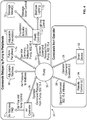
- FIG. 4 is a conceptual diagram depicting communications between a pump of an air bed system and various peripheral devices, in accordance with this disclosure.
- the pump 32 is a hub of the air bed system 30 with numerous peripherals in communication therewith.
- one or more users may use a smart device 22 or remote control 34 to transmit control signals to the pump 32.
- the smart device 22 may transmit control signals 28 wirelessly to the pump 32 using Bluetooth LE and the remote control 34 may transmit control signals wirelessly to the pump 32 using IEEE. 802.15.4.
- the pump 32 may act on the command, e.g., adjusting the air pressure to the adjustable air mattress 18, or transmit the control signal to one of the peripherals in the system.
- the peripherals may include, but are not limited to, an air mattress pad 17, the adjustable foundation 20, a massage motor 70, and bedroom lighting 72.
- the flexfit or foundation controller 14 may control operation of the adjustable foundation 20, the massage motor 70, and the bedroom lighting 72 using wireless control signals 35 sent using IEEE 802.15.4, for example, from the pump 32.
- the air controller or thermoelectric engine 16 may control operation of the air mattress pad 17 using wireless control signals 35 sent using IEEE 802.15.4, for example, from the pump 32.
- one or more future peripherals 74 may be wirelessly controlled by the pump 32, e.g., using control signals sent using IEEE 802.15.4. Because the system peripherals and, in particular, the future peripherals 74, may wirelessly pair with the pump 32, the expandability of the air bed system is not constrained by any physical connectors. For example, the air bed system of this disclosure is not constrained by the number of connectors that may be mounted on the system hub, e.g., the pump 32. As such, future peripherals 74 may be easily added to the air bed system 30 by the user in an almost limitless fashion, constrained only by the number of bindings supported by the controller of the pump 32.
- Future peripherals 74 include, but are not limited to, a home alarm system, home lighting, television(s), room shades, and room and/or home temperature.
- the user may pair the future peripheral 74 to the pump 32 and begin controlling that particular device, e.g., a television, using the control signals sent to the pump 32 from the smart device 22 or a universal remote control 34, for example.
- the air bed system 30 of this disclosure is designed for unknown, future peripherals to allow for seamless communication and expandability.
- An ad-hoc pairing between a peripheral and the pump 32 may be created by automatically or manually binding at least two devices, e.g., a future peripheral such as a television and the pump 32.
- a future peripheral such as a television and the pump 32.
- the creation of ad-hoc wireless networks is well known to those of ordinary skill in the art and, as such, need not be described in detail in this disclosure.
- the peripherals may include firmware to allow for automatic firmware updates upon binding with the pump 32.
- a new peripheral e.g., a television
- the updated user interface may include features specific to control of the new peripheral, e.g., the television.
- the new peripheral includes the new firmware for the remote control 34 and/or the pump 32, reduces or eliminates the need for the centralized server 38 of FIG. 2 to perform a full push of the firmware out to the pump 32 (and then to the remote control 34, for example).
- the controllers and devices described above may each include a processor, a storage device, and a network interface.
- the processor may be a general purpose central processing unit (CPU) or application-specific integrated circuit (ASIC).
- the storage device may include volatile or non-volatile static storage (e.g., Flash memory, RAM, EPROM, etc.).
- the storage device may store instructions which, when executed by the processor, configure the processor to perform the functionality described herein.
- a processor of the foundation controller may be configured to send a command to a motor to adjust a position of the foundation.
- the network interface of the components may be configured to transmit and receive communications in a variety of wired and wireless protocols.
- the network interface may be configured to use the 802.11 standards (e.g., 802.11a/b/c/g/n/ac), PAN network standards such as 802.15.4 or Bluetooth, infrared, cellular standards (e.g., 3G/4G etc.), Ethernet, and USB for receiving and transmitting data.
- 802.11 e.g., 802.11a/b/c/g/n/ac
- PAN network standards such as 802.15.4 or Bluetooth
- infrared e.g., cellular standards (e.g., 3G/4G etc.)
- Ethernet e.g., USB 2.0
- USB Universal Serial Bus 2.0
- the pump 32 is configured to analyze data collected by a pressure transducer to determine various states of a person lying on the bed. For example, the pump 32 may determine the heart rate or respiration rate of a person lying in the bed. Additional processing may be done using the collected data to determine a possible sleep state of the person. For example, the pump 32 may determine when a person falls asleep and, while asleep, the various sleep states of the person. Further, because the pump 32 acts a hub to the system and, as such, has state awareness of all of the peripheral devices, e.g., the foundation controller 14, a television, the thermoelectric engine 16, the pump may utilize the state information to analyze sleep data of the user.
- the peripheral devices e.g., the foundation controller 14, a television
- the pump 32 (in particular the controller of the pump 32) may determine that a user achieves a desired sleep state more quickly if the adjustable foundation is in a particular position.
- the pump 32 may communicate this analysis to the computer 54, thereby allowing the user to react accordingly.
Landscapes
- Mattresses And Other Support Structures For Chairs And Beds (AREA)
- Engineering & Computer Science (AREA)
- Invalid Beds And Related Equipment (AREA)
- General Engineering & Computer Science (AREA)
- Selective Calling Equipment (AREA)
- Mechanical Engineering (AREA)
- Physics & Mathematics (AREA)
- General Physics & Mathematics (AREA)
- Automation & Control Theory (AREA)
Claims (13)
- Système de lit gonflable (30), comprenant :une pluralité de dispositifs périphériques (16, 17, 18, 20, 70, 72, 74) ; etune unité pompe configurée pour régler une fermeté d'un matelas gonflable dudit système de lit gonflable (30), l'unité pompe comprenant :une pompe (32) ; etun contrôleur (14) configuré pour exécuter des instructions qui amènent l'unité pompe à s'apparier sans fil avec au moins un dispositif périphérique de la pluralité de dispositifs périphériques ;un corps d'unité pompe contenant la pompe (32) et le contrôleur (14) de l'unité pompe, ledit matelas gonflable comprenant une chambre à air (18), la pompe (32) étant connectée fluidiquement à la chambre à air (18) par un tuyau d'air s'étendant du corps d'unité pompe à la chambre à air (18), et la pluralité de dispositifs périphériques (16, 17, 18, 20, 70, 72, 74) étant externes au corps d'unité pompe et à la chambre à air (18),l'unité pompe étant configurée pour :recevoir au moins un signal de commande adressé à au moins un dispositif périphérique de la pluralité de dispositifs périphériques (16, 17, 18, 20, 70, 72, 74), ettransmettre l'au moins un signal de commande au dispositif périphérique (16, 17, 18, 20, 70, 72, 74) à qui le signal de commande est adressé.
- Système de lit gonflable selon la revendication 1, dans lequel la pluralité de dispositifs périphériques comprend un premier dispositif périphérique ayant un contrôle de dispositif périphérique configuré pour :recevoir l'au moins un signal de commande transmis par le contrôleur du dispositif pompe ; etcommander le comportement du dispositif périphérique associé selon l'au moins un signal de commande.
- Système de lit gonflable selon la revendication 1 ou 2, dans lequel la pluralité de dispositifs périphériques comprennent :un socle réglable (20) comportant un contrôleur de socle réglable (14) en communication avec le contrôleur de l'unité pompe pour recevoir un ou plusieurs signaux de commande transmis par le contrôleur de l'unité pompe ; etun couvre-matelas gonflable (17) comportant un contrôleur d'air en communication avec le contrôleur de l'unité pompe pour recevoir un ou plusieurs signaux de commande transmis par le contrôleur de l'unité pompe.
- Système de lit gonflable selon la revendication 1, 2 ou 3, dans lequel la pluralité de dispositifs périphériques sont physiquement séparés de l'unité pompe.
- Système de lit gonflable selon la revendication 1, 2, 3 ou 4, dans lequel le contrôleur de l'unité pompe est configuré pour exécuter des instructions qui amènent l'unité pompe à :former un réseau sans fil (56) avec la pluralité de dispositifs périphériques, chacun des dispositifs périphériques comprenant un contrôleur de dispositif périphérique configuré pour 1) former le réseau sans fil avec l'unité pompe, et 2) commander le comportement du dispositif périphérique associé selon un signal de commande reçu du dispositif pompe sur le réseau sans fil (56) ; ettransmettre au moins un signal de commande à un contrôleur de dispositif périphérique de la pluralité de contrôleurs de dispositif périphérique sur le réseau sans fil.
- Système de lit gonflable selon la revendication 1, 2, 3, 4 ou 5, dans lequel l'unité pompe comprend une enceinte qui loge physiquement la pompe et le contrôleur.
- Système de lit gonflable selon la revendication 5 ou 6, dans lequel les instructions amènent en outre l'unité pompe à :détecter un nouveau dispositif périphérique comprenant un contrôleur de dispositif périphérique configuré pour 1) former le réseau sans fil avec l'unité pompe, et 2) commander le comportement du dispositif périphérique associé selon un signal de commande reçu du dispositif pompe sur le réseau sans fil ; etajouter le nouveau dispositif périphérique au réseau sans fil.
- Système de lit gonflable selon la revendication 5, 6 ou 7, dans lequel les instructions amènent en outre l'unité pompe à recevoir une mise à jour de données configurée pour modifier une interface d'utilisateur pour inclure des caractéristiques spécifiques du nouveau dispositif périphérique.
- Système de lit gonflable selon la revendication 5, 6, 7 ou 8, dans lequel les instructions amènent en outre l'unité pompe à recevoir une mise à jour de données en provenance du nouveau dispositif périphérique.
- Procédé de fonctionnement d'une unité pompe d'un système de lit gonflable (30), l'unité pompe comprenant une pompe (32), un contrôleur (14) et un corps d'unité pompe contenant la pompe (32) et le contrôleur (14) de l'unité pompe, un matelas gonflable dudit système de lit gonflable (30) comprenant une chambre à air (18), la pompe (32) étant connectée fluidiquement à la chambre à air (18) par un tuyau d'air s'étendant du corps d'unité pompe à la chambre à air (18), et une pluralité de dispositifs périphériques (16, 17, 18, 20, 70, 72, 74) étant externes au corps d'unité pompe et à la chambre à air (18), le procédé consistant à :régler une fermeté du matelas gonflable par l'intermédiaire de l'unité pompe en commandant la pompe (32) pour modifier la pression d'air dans la chambre à air (18) du matelas gonflable ;exécuter des instructions par l'intermédiaire du contrôleur (14) de l'unité pompe pour amener la pompe (32) à s'apparier sans fil avec au moins un dispositif périphérique de la pluralité de dispositifs périphériques (16, 17, 18, 20, 70, 72, 74) ;recevoir, par l'intermédiaire du contrôleur (14) de l'unité pompe, au moins un signal de commande adressé à au moins un dispositif périphérique de la pluralité de dispositifs périphériques (16, 17, 18, 20, 70, 72, 74) ; ettransmettre, par l'intermédiaire du contrôleur (14) de l'unité pompe, l'au moins un signal de commande à l'au moins un dispositif périphérique de la pluralité de dispositifs périphériques (16, 17, 18, 20, 70, 72, 74).
- Procédé selon la revendication 10, dans lequel la pluralité de dispositifs périphériques comprend un premier dispositif périphérique ayant un contrôle de dispositif périphérique, le procédé consistant en outre à :recevoir, par le contrôleur de dispositif périphérique, l'au moins un signal de commande transmis par le contrôleur du dispositif pompe ; etcommander, par le contrôleur de dispositif périphérique, le comportement du dispositif périphérique associé selon l'au moins un signal de commande.
- Procédé selon la revendication 10 ou 11, le procédé consistant en outre à :former, par l'intermédiaire de l'unité pompe, un réseau sans fil (56) avec la pluralité de dispositifs périphériques, chacun des dispositifs périphériques comprenant un contrôleur de dispositif périphérique configuré pour 1) former le réseau sans fil avec l'unité pompe, et 2) commander le comportement du dispositif périphérique associé selon un signal de commande reçu du dispositif pompe sur le réseau sans fil (56) ; ettransmettre, par l'intermédiaire de l'unité pompe, au moins un signal de commande à un contrôleur de dispositif périphérique de la pluralité de contrôleurs de dispositif périphérique sur le réseau sans fil.
- Procédé selon la revendication 12, le procédé comprenant en outre l'étape consistant à :détecter un nouveau dispositif périphérique par l'intermédiaire du contrôleur de l'unité pompe ;ajouter le nouveau dispositif périphérique au réseau sans fil par l'intermédiaire du contrôleur de l'unité pompe ; etrecevoir, par l'intermédiaire du contrôleur de l'unité pompe, une mise à jour de données pour modifier une interface d'utilisateur pour inclure des caractéristiques spécifiques du nouveau dispositif périphérique, la mise à jour de données étant reçue du nouveau dispositif périphérique.
Priority Applications (1)
| Application Number | Priority Date | Filing Date | Title |
|---|---|---|---|
| EP19157945.7A EP3527110A1 (fr) | 2013-12-30 | 2014-12-30 | Matelas gonflable à commande intégrée |
Applications Claiming Priority (2)
| Application Number | Priority Date | Filing Date | Title |
|---|---|---|---|
| US201361921615P | 2013-12-30 | 2013-12-30 | |
| PCT/US2014/072814 WO2015103301A1 (fr) | 2013-12-30 | 2014-12-30 | Matelas gonflable à commande intégrée |
Related Child Applications (1)
| Application Number | Title | Priority Date | Filing Date |
|---|---|---|---|
| EP19157945.7A Division EP3527110A1 (fr) | 2013-12-30 | 2014-12-30 | Matelas gonflable à commande intégrée |
Publications (3)
| Publication Number | Publication Date |
|---|---|
| EP3089623A1 EP3089623A1 (fr) | 2016-11-09 |
| EP3089623A4 EP3089623A4 (fr) | 2017-09-13 |
| EP3089623B1 true EP3089623B1 (fr) | 2019-02-20 |
Family
ID=53480423
Family Applications (2)
| Application Number | Title | Priority Date | Filing Date |
|---|---|---|---|
| EP14877378.1A Active EP3089623B1 (fr) | 2013-12-30 | 2014-12-30 | Matelas gonflable à commande intégrée |
| EP19157945.7A Withdrawn EP3527110A1 (fr) | 2013-12-30 | 2014-12-30 | Matelas gonflable à commande intégrée |
Family Applications After (1)
| Application Number | Title | Priority Date | Filing Date |
|---|---|---|---|
| EP19157945.7A Withdrawn EP3527110A1 (fr) | 2013-12-30 | 2014-12-30 | Matelas gonflable à commande intégrée |
Country Status (5)
| Country | Link |
|---|---|
| US (1) | US9770114B2 (fr) |
| EP (2) | EP3089623B1 (fr) |
| AU (1) | AU2014373806B2 (fr) |
| CA (1) | CA2945694C (fr) |
| WO (1) | WO2015103301A1 (fr) |
Families Citing this family (93)
| Publication number | Priority date | Publication date | Assignee | Title |
|---|---|---|---|---|
| US20080077020A1 (en) | 2006-09-22 | 2008-03-27 | Bam Labs, Inc. | Method and apparatus for monitoring vital signs remotely |
| US8769747B2 (en) | 2008-04-04 | 2014-07-08 | Select Comfort Corporation | System and method for improved pressure adjustment |
| US8332975B2 (en) | 2009-08-31 | 2012-12-18 | Gentherm Incorporated | Climate-controlled topper member for medical beds |
| US9131781B2 (en) | 2012-12-27 | 2015-09-15 | Select Comfort Corporation | Distribution pad for a temperature control system |
| CA2905277C (fr) | 2013-03-11 | 2018-03-27 | Select Comfort Corporation | Moyens de commutation pour un systeme a supports reglables |
| EP2967224B2 (fr) | 2013-03-14 | 2023-02-22 | Select Comfort Corporation | Système de matelas pneumatique gonflable ayant des techniques de détection |
| EP3202284B1 (fr) | 2013-03-14 | 2018-10-03 | Select Comfort Corporation | Détection de ronflement et réponse pour un matelas pneumatique gonflable |
| JP6126300B2 (ja) | 2013-03-14 | 2017-05-10 | セレクト コンフォート コーポレーションSelect Comfort Corporation | 照明及び音声制御装置を備えた膨張式エアマットレス |
| US10182661B2 (en) | 2013-03-14 | 2019-01-22 | Sleep Number Corporation and Select Comfort Retail Corporation | Inflatable air mattress alert and monitoring system |
| AU2014236803B2 (en) | 2013-03-14 | 2017-03-16 | Sleep Number Corporation | Inflatable air mattress autofill and off bed pressure adjustment |
| AU2014236557B2 (en) | 2013-03-14 | 2016-10-06 | Sleep Number Corporation | Inflatable air mattress system architecture |
| US8984687B2 (en) | 2013-03-14 | 2015-03-24 | Select Comfort Corporation | Partner snore feature for adjustable bed foundation |
| US9504416B2 (en) | 2013-07-03 | 2016-11-29 | Sleepiq Labs Inc. | Smart seat monitoring system |
| US9445751B2 (en) | 2013-07-18 | 2016-09-20 | Sleepiq Labs, Inc. | Device and method of monitoring a position and predicting an exit of a subject on or from a substrate |
| US10674832B2 (en) | 2013-12-30 | 2020-06-09 | Sleep Number Corporation | Inflatable air mattress with integrated control |
| US20160015184A1 (en) | 2014-03-13 | 2016-01-21 | Select Comfort Corporation | Automatic sensing and adjustment of a bed system |
| US10143312B2 (en) | 2014-04-15 | 2018-12-04 | Sleep Number Corporation | Adjustable bed system |
| US9888785B2 (en) | 2014-04-21 | 2018-02-13 | Casper Sleep Inc. | Mattress |
| US10448749B2 (en) | 2014-10-10 | 2019-10-22 | Sleep Number Corporation | Bed having logic controller |
| US10342358B1 (en) * | 2014-10-16 | 2019-07-09 | Sleep Number Corporation | Bed with integrated components and features |
| EP3242576B8 (fr) | 2015-01-05 | 2026-01-14 | Sleep Number Corporation | Lit avec suivi d'occupation par un utilisateur |
| US9917457B2 (en) | 2015-02-02 | 2018-03-13 | Black & Decker Inc. | Power tool with USB connection |
| US10441087B2 (en) | 2015-02-24 | 2019-10-15 | Sleep Number Corporation | Mattress with adjustable firmness |
| US9924813B1 (en) | 2015-05-29 | 2018-03-27 | Sleep Number Corporation | Bed sheet system |
| WO2017003764A1 (fr) | 2015-07-02 | 2017-01-05 | Select Comfort Corporation | Automatisation pour qualité de sommeil améliorée |
| US10149549B2 (en) | 2015-08-06 | 2018-12-11 | Sleep Number Corporation | Diagnostics of bed and bedroom environment |
| US10736473B2 (en) * | 2015-08-26 | 2020-08-11 | Robert Rife | Toilet |
| EP3362688B1 (fr) | 2015-10-16 | 2024-07-31 | Intex Marketing Ltd. | Pompe à air multifonctionnelle |
| US10711788B2 (en) | 2015-12-17 | 2020-07-14 | Wayne/Scott Fetzer Company | Integrated sump pump controller with status notifications |
| US10539170B2 (en) | 2015-12-31 | 2020-01-21 | Sleep Number Corporation | Foundation and frame for bed |
| USD812393S1 (en) | 2016-09-15 | 2018-03-13 | Sleep Number Corporation | Bed |
| US11284725B2 (en) * | 2016-10-25 | 2022-03-29 | Daniel Moss | Inflatable mattress bumper system |
| US10993546B2 (en) | 2016-10-28 | 2021-05-04 | Sleep Number Corporation | Noise reducing plunger |
| US10677232B2 (en) | 2016-10-28 | 2020-06-09 | Sleep Number Corporation | Pump with vibration isolators |
| US10888173B2 (en) | 2016-10-28 | 2021-01-12 | Sleep Number Corporation | Air controller with vibration isolators |
| US10575654B2 (en) | 2016-10-28 | 2020-03-03 | Sleep Number Corporation | Air manifold |
| US10827846B2 (en) | 2016-10-28 | 2020-11-10 | Sleep Number Corporation | Bed with foot warming system |
| USD809843S1 (en) | 2016-11-09 | 2018-02-13 | Sleep Number Corporation | Bed foundation |
| US11140999B2 (en) | 2016-11-09 | 2021-10-12 | Select Comfort Corporation | Bed with magnetic couplers |
| USD932808S1 (en) | 2016-11-09 | 2021-10-12 | Select Comfort Corporation | Mattress |
| US10729253B1 (en) | 2016-11-09 | 2020-08-04 | Sleep Number Corporation | Adjustable foundation with service position |
| CN206368786U (zh) | 2016-12-08 | 2017-08-01 | 明达实业(厦门)有限公司 | 泵与充气产品的连接结构 |
| CA3004999A1 (fr) * | 2017-05-16 | 2018-11-16 | Aqua-Leisure Industries, Inc. | Systemes et methodes de controle d'un dispositif gonflable |
| DE202017102949U1 (de) * | 2017-05-16 | 2018-08-17 | Dewertokin Gmbh | Steuerungseinrichtung und Steuerungssystem für einen elektromotorischen Verstellantrieb eines Möbels |
| USD893552S1 (en) | 2017-06-21 | 2020-08-18 | Wayne/Scott Fetzer Company | Pump components |
| US11116326B2 (en) | 2017-08-14 | 2021-09-14 | Casper Sleep Inc. | Mattress containing ergonomic and firmness-regulating endoskeleton |
| US10772438B2 (en) | 2017-08-23 | 2020-09-15 | Sleep Number Corporation | Air system for a bed |
| CN208669644U (zh) | 2018-05-16 | 2019-03-29 | 明达实业(厦门)有限公司 | 一种具有多通道充放气功能的泵浦 |
| EP4379217A3 (fr) | 2017-11-27 | 2024-08-28 | Intex Marketing Ltd. | Structure de réglage manuel de gonflage et de dégonflage d'une pompe |
| EP3731698B1 (fr) | 2017-12-28 | 2023-10-11 | Sleep Number Corporation | Lit ayant un élément de détection de ronflement |
| US10957335B2 (en) | 2017-12-28 | 2021-03-23 | Sleep Number Corporation | Home automation having user privacy protections |
| US11737938B2 (en) | 2017-12-28 | 2023-08-29 | Sleep Number Corporation | Snore sensing bed |
| US12564526B2 (en) | 2017-12-28 | 2026-03-03 | Sleep Number Corporation | Bed having sensor fusing features useful for determining snore and breathing parameters |
| US11571346B2 (en) | 2017-12-28 | 2023-02-07 | Sleep Number Corporation | Bed having rollover identifying feature |
| WO2019133664A1 (fr) | 2017-12-28 | 2019-07-04 | Sleep Number Corporation | Lit ayant un élément de détection de stade de sommeil |
| AU2018399606B2 (en) | 2018-01-05 | 2024-09-12 | Ramazan Demirli | Bed having physiological event detecting feature |
| USD890211S1 (en) | 2018-01-11 | 2020-07-14 | Wayne/Scott Fetzer Company | Pump components |
| CN112839566A (zh) | 2018-03-07 | 2021-05-25 | 数眠公司 | 基于家庭的压力测试 |
| WO2019209733A1 (fr) | 2018-04-23 | 2019-10-31 | Casper Sleep Inc. | Matelas de régulation de température |
| US11001447B2 (en) | 2018-09-05 | 2021-05-11 | Sleep Number Corporation | Lifting furniture |
| AU2019379575B2 (en) | 2018-11-14 | 2025-11-27 | Sleep Number Corporation | Using force sensors to determine sleep parameters |
| US11653769B2 (en) | 2018-12-14 | 2023-05-23 | Sleep Technologies, Llc | Methods and systems of spring modules for an adjustable sleeping system |
| CA3103532A1 (fr) | 2018-12-31 | 2020-07-09 | Sleep Number Corporation | Domotique a caracteristiques d'amelioration du sommeil |
| USD968436S1 (en) | 2019-01-08 | 2022-11-01 | Sleep Number Corporation | Display screen or portion thereof with graphical user interface |
| US12123763B2 (en) | 2019-02-12 | 2024-10-22 | Sleep Number Corporation | Load sensor assembly for bed leg and bed with load sensor assembly |
| EP3952723A1 (fr) | 2019-04-08 | 2022-02-16 | Sleep Number Corporation | Système de détection et de commande d'un environnement de lit |
| WO2020214219A1 (fr) | 2019-04-16 | 2020-10-22 | Sleep Number Corporation | Oreiller avec charge sans fil |
| AU2019442048B2 (en) | 2019-04-25 | 2026-01-22 | Sleep Number Corporation | Bed having features for improving a sleeper's body thermoregulation during sleep |
| USD916745S1 (en) | 2019-05-08 | 2021-04-20 | Sleep Number Corporation | Display screen or portion thereof with graphical user interface |
| AU2019444063A1 (en) | 2019-06-03 | 2020-12-17 | Sleep Number Corporation | Mattress covering |
| US11698075B2 (en) | 2019-06-21 | 2023-07-11 | Intex Marketing Ltd. | Inflatable product having electric and manual pumps |
| USD908398S1 (en) | 2019-08-27 | 2021-01-26 | Casper Sleep Inc. | Mattress |
| USD927889S1 (en) | 2019-10-16 | 2021-08-17 | Casper Sleep Inc. | Mattress layer |
| US11497322B2 (en) | 2019-11-15 | 2022-11-15 | Sleep Number Corporation | Zipper mattress attachment |
| USD1083443S1 (en) | 2019-12-31 | 2025-07-15 | Sleep Number Corporation | Mattress |
| WO2021138527A2 (fr) | 2020-01-03 | 2021-07-08 | Sleep Number Corporation | Régulation de l'écoulement d'air et de la température d'un lit |
| AU2021229476A1 (en) | 2020-03-02 | 2022-06-16 | Sleep Number Corporation | Bed having user context sensing features |
| JP7691999B2 (ja) | 2020-04-01 | 2025-06-12 | スリープ ナンバー コーポレイション | 遠隔患者のスクリーニング及びトリアージのためのシステム及び方法 |
| KR102833920B1 (ko) * | 2020-05-07 | 2025-07-11 | 엘지전자 주식회사 | 스마트 매트에 기반하여 홈 내의 전자 장치를 제어하는 장치 및 방법과, 상기 스마트 매트를 제어하는 장치 및 방법 |
| US12186241B2 (en) | 2021-01-22 | 2025-01-07 | Hill-Rom Services, Inc. | Time-based wireless pairing between a medical device and a wall unit |
| US12279999B2 (en) | 2021-01-22 | 2025-04-22 | Hill-Rom Services, Inc. | Wireless configuration and authorization of a wall unit that pairs with a medical device |
| KR20240004797A (ko) | 2021-05-06 | 2024-01-11 | 슬립 넘버 코포레이션 | 심장 파라미터 및 외부 온도의 감지로부터 심부 체온을 추정하는 피처를 갖는 침대 |
| US12369848B2 (en) | 2021-06-08 | 2025-07-29 | Sleep Number Corporation | Determining real-time sleep states using machine learning techniques |
| US11832728B2 (en) | 2021-08-24 | 2023-12-05 | Sleep Number Corporation | Controlling vibration transmission within inflation assemblies |
| USD1018476S1 (en) | 2021-11-09 | 2024-03-19 | Sleep Number Corporation | Remote control |
| US12408763B2 (en) | 2021-11-10 | 2025-09-09 | Sleep Number Corporation | Controlling a bed remotely |
| WO2023086476A1 (fr) | 2021-11-15 | 2023-05-19 | Sleep Number Corporation | Matelas pneumatique doté de caractéristiques permettant de déterminer la température ambiante |
| WO2023129447A1 (fr) | 2021-12-30 | 2023-07-06 | Sleep Number Corporation | Système de lit à poches de rangement de charge de dispositif |
| CN118475275A (zh) | 2021-12-30 | 2024-08-09 | 数眠公司 | 具有背向灯的床头板 |
| WO2023129473A2 (fr) | 2021-12-30 | 2023-07-06 | Sleep Number Corporation | Système de lit à station d'accueil intégrée pour télécommande et lampe de lecture |
| CN115153246B (zh) * | 2022-06-28 | 2024-06-14 | 宁波乐歌舒蔓卫浴科技有限公司 | 一种电动床控制系统、电动床系统 |
| US12593928B2 (en) | 2022-07-01 | 2026-04-07 | Sleep Technologies, Llc | Spring modules for an adjustable sleeping system |
| US12557916B2 (en) | 2023-04-20 | 2026-02-24 | Sleep Number Corporation | Bed system for detecting snore side |
Citations (1)
| Publication number | Priority date | Publication date | Assignee | Title |
|---|---|---|---|---|
| US20130031725A1 (en) * | 2011-08-02 | 2013-02-07 | Rapid Air, Llc | System and Method for Controlling Air Mattress Inflation and Deflation |
Family Cites Families (201)
| Publication number | Priority date | Publication date | Assignee | Title |
|---|---|---|---|---|
| US3727606A (en) | 1970-06-12 | 1973-04-17 | Airco Inc | Apnea detection device |
| US4146885A (en) | 1977-10-13 | 1979-03-27 | Lawson Jr William H | Infant bed and apnea alarm |
| US4299233A (en) | 1979-10-03 | 1981-11-10 | Lemelson Jerome H | Patient monitoring device and method |
| US4662012A (en) | 1983-12-07 | 1987-05-05 | Torbet Philip A | Bed utilizing an air mattress |
| US4657026A (en) | 1986-07-14 | 1987-04-14 | Tagg James R | Apnea alarm systems |
| US5802640A (en) | 1992-04-03 | 1998-09-08 | Hill-Rom, Inc. | Patient care system |
| US5062169A (en) | 1990-03-09 | 1991-11-05 | Leggett & Platt, Incorporated | Clinical bed |
| FI915228A7 (fi) | 1990-03-09 | 1991-11-06 | Matsushita Electric Industrial Co Ltd | Unenhavaitsemislaite |
| US5197490A (en) | 1990-04-19 | 1993-03-30 | Cta Bio Services, Inc. | Information processing system for counting coughs or evaluating other activities of a patient |
| US5235258A (en) * | 1991-03-27 | 1993-08-10 | Santino Antinori | Remotely controlled articulated bed |
| US5170522A (en) | 1991-12-16 | 1992-12-15 | Select Comfort Corporation | Air adjustable bed |
| US5459452A (en) | 1992-03-30 | 1995-10-17 | Deponte; Dominic A. | Wet bed and patient wander alarm system with snap-on and magnet transmitter assembly |
| CA2100183A1 (fr) | 1993-07-07 | 1995-01-08 | Bill B. Culp | Matelas d'air auto-gonflable |
| US5699038A (en) | 1993-07-12 | 1997-12-16 | Hill-Rom, Inc. | Bed status information system for hospital beds |
| US6897780B2 (en) | 1993-07-12 | 2005-05-24 | Hill-Rom Services, Inc. | Bed status information system for hospital beds |
| US5684460A (en) | 1994-04-22 | 1997-11-04 | The United States Of America As Represented By The Secretary Of The Army | Motion and sound monitor and stimulator |
| US5515865A (en) | 1994-04-22 | 1996-05-14 | The United States Of America As Represented By The Secretary Of The Army | Sudden Infant Death Syndrome (SIDS) monitor and stimulator |
| US5564140A (en) | 1994-07-22 | 1996-10-15 | Select Comfort Corporation | Frame assembly for supporting a mattress |
| US5509154A (en) | 1994-11-01 | 1996-04-23 | Select Comfort Corporation | Air control system for an air bed |
| AUPN304895A0 (en) | 1995-05-19 | 1995-06-15 | Somed Pty Limited | Device for detecting and recording snoring |
| US7017208B2 (en) | 1995-08-04 | 2006-03-28 | Hill-Rom Services, Inc. | Hospital bed |
| US5771511A (en) | 1995-08-04 | 1998-06-30 | Hill-Rom, Inc. | Communication network for a hospital bed |
| US5642546A (en) | 1995-09-19 | 1997-07-01 | Select Comfort Corporation | Inflatable mattress with improved border support wall |
| DE19538473A1 (de) | 1995-10-16 | 1997-04-17 | Map Gmbh | Vorrichtung und Verfahren zur quantitativen Analyse von Schlafstörungen |
| US5848450A (en) | 1996-03-05 | 1998-12-15 | L&P Property Management Company | Air bed control |
| US5815864A (en) * | 1996-04-02 | 1998-10-06 | Sytron Corporation | Microprocessor controller and method of initializing and controlling low air loss floatation mattress |
| US5796340A (en) | 1996-08-12 | 1998-08-18 | Miller; William | Motion monitor useful for sleeping humans |
| US6778090B2 (en) | 1996-09-04 | 2004-08-17 | Paul Newham | Modular system for monitoring the presence of a person using a variety of sensing devices |
| DE19649991A1 (de) | 1996-11-21 | 1998-06-04 | Axon Gmbh Schmalkalden | Verfahren zur Ermittlung von Schlaf- und Wachprofilen |
| IL119721A (en) | 1996-11-29 | 2005-08-31 | Mindlife Ltd | Method and system for monitoring the physiological condition of a patient |
| US6062216A (en) | 1996-12-27 | 2000-05-16 | Children's Medical Center Corporation | Sleep apnea detector system |
| US6546813B2 (en) | 1997-01-08 | 2003-04-15 | The Trustees Of Boston University | Patient monitoring system employing array of force sensors on a bedsheet or similar substrate |
| JPH10313981A (ja) * | 1997-05-15 | 1998-12-02 | Aihou:Kk | エアーベッド |
| JP2001525706A (ja) | 1997-05-16 | 2001-12-11 | レスメッド・リミテッド | 呼吸分析システム |
| US5904172A (en) | 1997-07-28 | 1999-05-18 | Select Comfort Corporation | Valve enclosure assembly |
| US5844488A (en) | 1997-09-23 | 1998-12-01 | Musick; Jeff L. | Bed sensor and alarm |
| US6008598A (en) * | 1998-04-22 | 1999-12-28 | Patmark Company, Inc. | Hand-held controller for bed and mattress assembly |
| WO1999043240A1 (fr) | 1998-02-25 | 1999-09-02 | Select Comfort Corporation | Support multi-zones |
| ID27521A (id) | 1998-03-11 | 2001-04-12 | Sleep Tec Inc | Sofa tidur dengan kasur udara |
| US6024699A (en) | 1998-03-13 | 2000-02-15 | Healthware Corporation | Systems, methods and computer program products for monitoring, diagnosing and treating medical conditions of remotely located patients |
| DE29806588U1 (de) | 1998-04-15 | 1998-08-13 | Dewert Antriebs- Und Systemtechnik Gmbh & Co. Kg, 32278 Kirchlengern | Krankenhaus- oder Pflegebett |
| US5948303A (en) | 1998-05-04 | 1999-09-07 | Larson; Lynn D. | Temperature control for a bed |
| US6058537A (en) * | 1998-07-13 | 2000-05-09 | Larson; Lynn D. | Pressure control apparatus for air mattresses |
| US6146332A (en) | 1998-07-29 | 2000-11-14 | 3416704 Canada Inc. | Movement detector |
| US6721980B1 (en) | 1998-10-28 | 2004-04-20 | Hill-Fom Services, Inc. | Force optimization surface apparatus and method |
| US6208250B1 (en) | 1999-03-05 | 2001-03-27 | Hill-Rom, Inc. | Patient position detection apparatus for a bed |
| US6397419B1 (en) | 1999-03-10 | 2002-06-04 | Select Comfort Corporation | System and method for sleep surface adjustment |
| AUPP974599A0 (en) | 1999-04-14 | 1999-05-06 | Resmed Limited | Detection and classification of breathing patterns |
| JP3820811B2 (ja) | 1999-08-02 | 2006-09-13 | 株式会社デンソー | 呼吸器系疾患のモニタ装置 |
| EP1093755B1 (fr) | 1999-10-19 | 2008-03-19 | Thomas Hilfen HILBEG GmbH & Co. Kommanditgesellschaft | Dispositif de mesure de paramètres d'une personne couchée |
| US20030166995A1 (en) | 2000-04-20 | 2003-09-04 | Klaus Jansen | Method and device for mneasuring vital parameters |
| US20040049132A1 (en) | 2000-06-15 | 2004-03-11 | The Procter & Gamble Company | Device for body activity detection and processing |
| US20020069462A1 (en) | 2000-07-07 | 2002-06-13 | Gaboury James D. | Bed foundation |
| US6883191B2 (en) | 2000-07-07 | 2005-04-26 | Select Comfort Corporation | Leg and bracket assembly for a bed foundation |
| US6468234B1 (en) | 2000-07-14 | 2002-10-22 | The Board Of Trustees Of The Leland Stanford Junior University | SleepSmart |
| US6485441B2 (en) | 2000-07-14 | 2002-11-26 | The Board Of Trustees Of The Leland Stanford Junior University | SensorBed |
| US7666151B2 (en) | 2002-11-20 | 2010-02-23 | Hoana Medical, Inc. | Devices and methods for passive patient monitoring |
| JP4641093B2 (ja) | 2000-10-31 | 2011-03-02 | 株式会社モルテン | エアマット |
| US6686711B2 (en) | 2000-11-15 | 2004-02-03 | Comfortaire Corporation | Air mattress control system and method |
| US6578214B2 (en) | 2001-03-07 | 2003-06-17 | Paula Peftoulidis | Sport beds |
| TW526056B (en) | 2001-03-15 | 2003-04-01 | Huntleigh Technology Plc | Inflatable support |
| US6671905B2 (en) | 2001-03-29 | 2004-01-06 | Kci Licensing, Inc. | Prone positioning therapeutic bed |
| ATE407592T1 (de) * | 2001-06-07 | 2008-09-15 | Select Comfort Corp | Interaktives luftbett |
| US6561047B1 (en) | 2001-07-03 | 2003-05-13 | Dreamwell, Ltd. | Method and system for analyzing motion transferred to a subject on a sleeping surface |
| US6708357B2 (en) | 2002-01-14 | 2004-03-23 | Select Comfort Corporation | Corner piece for a soft-sided mattress |
| US6807698B2 (en) | 2002-06-01 | 2004-10-26 | Sleepadvantage, Llc | Bed having low body pressure and alignment |
| CA2393880A1 (fr) | 2002-07-17 | 2004-01-17 | Tactex Controls Inc. | Systeme de surveillance pour l'occupant d'un lit |
| US20060020178A1 (en) | 2002-08-07 | 2006-01-26 | Apneos Corp. | System and method for assessing sleep quality |
| FI116097B (fi) | 2002-08-21 | 2005-09-15 | Heikki Ruotoistenmaeki | Voima- tai paineanturi ja menetelmä sen soveltamiseksi |
| JP4712385B2 (ja) | 2002-09-06 | 2011-06-29 | ヒル−ロム サービシーズ,インコーポレイティド | 病院ベッド |
| KR20050072435A (ko) | 2002-10-09 | 2005-07-11 | 컴퓨메딕스 리미티드 | 치료 처리중 수면 품질을 유지하고 모니터하기 위한 방법및 장치 |
| US6878121B2 (en) | 2002-11-01 | 2005-04-12 | David T. Krausman | Sleep scoring apparatus and method |
| JP2004229875A (ja) | 2003-01-30 | 2004-08-19 | Yokogawa Electric Corp | 就寝用具制御装置 |
| SE0300280L (sv) | 2003-02-04 | 2004-08-05 | Hilding Anders Internat Ab | Anordning och förfarande för att reglera fysikaliska egenskaper hos en säng |
| WO2004075714A2 (fr) | 2003-02-28 | 2004-09-10 | Cornel Lustig | Systeme et procede pour influer sur la structure du sommeil par des stimulations non intrusives ne provocant pas le reveil |
| US6847301B1 (en) | 2003-03-06 | 2005-01-25 | Personal Safety Corporation | Patient position monitoring device |
| JP4533889B2 (ja) * | 2003-03-12 | 2010-09-01 | ジェッタ カンパニー リミテッド | 調節可能マットレスおよび枕システム |
| US6804848B1 (en) | 2003-03-14 | 2004-10-19 | Comfortaire Corporation | High-profile mattress having an upper low-profile module with an air posturizing sleep surface |
| US20050038326A1 (en) | 2003-05-30 | 2005-02-17 | Michael Mathur | System, device, and method for remote monitoring and servicing |
| US6993380B1 (en) | 2003-06-04 | 2006-01-31 | Cleveland Medical Devices, Inc. | Quantitative sleep analysis method and system |
| US20050022606A1 (en) | 2003-07-31 | 2005-02-03 | Partin Dale L. | Method for monitoring respiration and heart rate using a fluid-filled bladder |
| US7532934B2 (en) | 2003-09-18 | 2009-05-12 | Cardiac Pacemakers, Inc. | Snoring detection system and method |
| US7399205B2 (en) | 2003-08-21 | 2008-07-15 | Hill-Rom Services, Inc. | Plug and receptacle having wired and wireless coupling |
| JP3733133B2 (ja) | 2003-10-14 | 2006-01-11 | 三洋電機株式会社 | 睡眠状態推定装置 |
| US7396331B2 (en) | 2003-10-27 | 2008-07-08 | Home Guardian, Llc | System and process for non-invasive collection and analysis of physiological signals |
| US7041049B1 (en) | 2003-11-21 | 2006-05-09 | First Principles, Inc. | Sleep guidance system and related methods |
| WO2005055824A1 (fr) | 2003-12-04 | 2005-06-23 | Hoana Medical, Inc. | Systeme de surveillance medicale intelligent |
| US7524279B2 (en) | 2003-12-31 | 2009-04-28 | Raphael Auphan | Sleep and environment control method and system |
| US8096960B2 (en) | 2004-01-09 | 2012-01-17 | Loree Iv Leonor F | Easy wake device |
| US7077810B2 (en) | 2004-02-05 | 2006-07-18 | Earlysense Ltd. | Techniques for prediction and monitoring of respiration-manifested clinical episodes |
| US20070118054A1 (en) | 2005-11-01 | 2007-05-24 | Earlysense Ltd. | Methods and systems for monitoring patients for clinical episodes |
| US8491492B2 (en) | 2004-02-05 | 2013-07-23 | Earlysense Ltd. | Monitoring a condition of a subject |
| US7314451B2 (en) | 2005-04-25 | 2008-01-01 | Earlysense Ltd. | Techniques for prediction and monitoring of clinical episodes |
| US8403865B2 (en) | 2004-02-05 | 2013-03-26 | Earlysense Ltd. | Prediction and monitoring of clinical episodes |
| IL160308A0 (en) | 2004-02-10 | 2004-07-25 | Itshak Y Ben Yesha | Method for determining heart rate |
| CN1942906A (zh) | 2004-02-18 | 2007-04-04 | 赫艾纳医疗公司 | 用于使无源传感器阵列与床垫结合而进行患者监视的方法和系统 |
| US7865988B2 (en) | 2004-03-16 | 2011-01-11 | Select Comfort Corporation | Sleeping surface having two longitudinally connected bladders with a support member |
| US7717848B2 (en) | 2004-03-16 | 2010-05-18 | Medtronic, Inc. | Collecting sleep quality information via a medical device |
| ATE478645T1 (de) | 2004-04-30 | 2010-09-15 | Hill Rom Services Inc | Patientenunterstützung |
| TW200611659A (en) | 2004-06-18 | 2006-04-16 | Jtmd Llc | Foam core pillow or mattress allowing adjustment for rebound speed |
| FI120961B (fi) | 2004-07-01 | 2010-05-31 | Emfit Oy | Menetelmä ja laitteisto elintoimintojen tai läsnäolon mittaamiseksi ja valvomiseksi |
| JP3976752B2 (ja) | 2004-07-07 | 2007-09-19 | 三洋電機株式会社 | 睡眠状態推定装置及びプログラム |
| US7319386B2 (en) | 2004-08-02 | 2008-01-15 | Hill-Rom Services, Inc. | Configurable system for alerting caregivers |
| US7852208B2 (en) | 2004-08-02 | 2010-12-14 | Hill-Rom Services, Inc. | Wireless bed connectivity |
| US20060047217A1 (en) | 2004-08-06 | 2006-03-02 | Mohsen Mirtalebi | Method and Apparatus for Infant Sleep Apnea Monitoring and Data Analysis |
| US7253366B2 (en) | 2004-08-09 | 2007-08-07 | Hill-Rom Services, Inc. | Exit alarm for a hospital bed triggered by individual load cell weight readings exceeding a predetermined threshold |
| EP1893822A4 (fr) | 2005-06-10 | 2013-07-03 | Hill Rom Services Inc | Controle de vessie sous pression dans un dispositif support pour patients |
| KR100791371B1 (ko) | 2005-10-07 | 2008-01-07 | 삼성전자주식회사 | 숙면 및 기상 유도 장치 및 방법 |
| JP4528710B2 (ja) | 2005-11-09 | 2010-08-18 | 株式会社東芝 | 睡眠状態計測装置、睡眠状態計測方法及び睡眠状態計測システム |
| US20070180047A1 (en) | 2005-12-12 | 2007-08-02 | Yanting Dong | System and method for providing authentication of remotely collected external sensor measures |
| US20070179334A1 (en) | 2006-01-30 | 2007-08-02 | Groves Laurie L | Sleep aid |
| JP5312053B2 (ja) | 2006-03-06 | 2013-10-09 | センシオテック インコーポレイテッド | 超広帯域モニタリング・システムおよびアンテナ |
| US7676872B2 (en) | 2006-04-05 | 2010-03-16 | Paul Block | Automated sleep system |
| NL1033142C2 (nl) | 2006-05-03 | 2007-11-06 | Pijnloos B V | Matras. |
| WO2007143535A2 (fr) | 2006-06-01 | 2007-12-13 | Biancamed Ltd. | Appareil, système et procédé de surveillance de signaux physiologiques |
| DK2030601T3 (da) | 2006-06-19 | 2012-12-17 | Showa Denko Kk | Fremgangsmåde til detektering af et individs tilstedeværelse på en seng |
| EP2040614B1 (fr) | 2006-07-05 | 2016-01-27 | Stryker Corporation | Système de détection et de contrôle de signes vitaux |
| US8083682B2 (en) | 2006-07-19 | 2011-12-27 | Cardiac Pacemakers, Inc. | Sleep state detection |
| US8073535B2 (en) | 2006-07-19 | 2011-12-06 | Invention Science Fund 1 | Radiant energy derived temperature(s) |
| WO2008048743A2 (fr) | 2006-08-29 | 2008-04-24 | Ascion Llc | Matelas à ressorts en mousse configuré avec une fermeté variable |
| US9591995B2 (en) | 2006-09-06 | 2017-03-14 | J. Seth Blumberg | Digital bed system |
| US7465280B2 (en) | 2006-09-14 | 2008-12-16 | Rawls-Meehan Martin B | Methods and systems of mounting a vibration motor to an adjustable bed |
| US8926535B2 (en) | 2006-09-14 | 2015-01-06 | Martin B. Rawls-Meehan | Adjustable bed position control |
| US20100199432A1 (en) | 2008-12-04 | 2010-08-12 | Rawls-Meehan Martin B | Truss-reinforced adjustable bed frame |
| US20120138067A1 (en) | 2007-09-14 | 2012-06-07 | Rawls-Meehan Martin B | System and method for mitigating snoring in an adjustable bed |
| US8069512B2 (en) | 2006-09-14 | 2011-12-06 | Martin B Rawls-Meehan | Adjustable bed frame |
| US20080077020A1 (en) | 2006-09-22 | 2008-03-27 | Bam Labs, Inc. | Method and apparatus for monitoring vital signs remotely |
| US20110144455A1 (en) | 2007-08-31 | 2011-06-16 | Bam Labs, Inc. | Systems and methods for monitoring a subject at rest |
| US20100170043A1 (en) | 2009-01-06 | 2010-07-08 | Bam Labs, Inc. | Apparatus for monitoring vital signs |
| US8280748B2 (en) | 2006-10-20 | 2012-10-02 | Hill-Rom Services, Inc. | Bed management |
| US7513003B2 (en) | 2006-11-14 | 2009-04-07 | L & P Property Management Company | Anti-snore bed having inflatable members |
| US7849545B2 (en) | 2006-11-14 | 2010-12-14 | Hill-Rom Industries Sa | Control system for hospital bed mattress |
| US20080126122A1 (en) | 2006-11-28 | 2008-05-29 | General Electric Company | Smart bed system and apparatus |
| US20080120784A1 (en) | 2006-11-28 | 2008-05-29 | General Electric Company | Smart bed system and apparatus |
| US20080122616A1 (en) | 2006-11-28 | 2008-05-29 | General Electric Company | Smart bed method |
| US20080126132A1 (en) | 2006-11-28 | 2008-05-29 | General Electric Company | Smart bed system |
| US20080147442A1 (en) | 2006-12-18 | 2008-06-19 | General Electric Company | Smart bed system and apparatus |
| US7868757B2 (en) | 2006-12-29 | 2011-01-11 | Nokia Corporation | Method for the monitoring of sleep using an electronic device |
| US7953613B2 (en) | 2007-01-03 | 2011-05-31 | Gizewski Theodore M | Health maintenance system |
| US7886387B2 (en) * | 2007-01-26 | 2011-02-15 | Rapid Air Llc | Multiple configuration air mattress pump system |
| US20100094139A1 (en) | 2007-02-28 | 2010-04-15 | Koninklijke Philips Electronics N. V. | System and method for obtaining physiological data of a patient |
| TWI317630B (en) | 2007-03-12 | 2009-12-01 | Taiwan Textile Res Inst | Respiration monitoring system |
| US8276585B2 (en) | 2007-04-10 | 2012-10-02 | Resmed Limited | Systems and methods for visualizing pressures and pressure responses to sleep-related triggering events |
| US20080262657A1 (en) * | 2007-04-17 | 2008-10-23 | L&P Property Management Company | System and method for controlling adjustable furniture |
| WO2008143621A1 (fr) | 2007-05-24 | 2008-11-27 | Select Comfort Corporation | Système et procédé de détection d'une fuite dans un matelas pneumatique |
| JP5073371B2 (ja) | 2007-06-06 | 2012-11-14 | 株式会社タニタ | 睡眠評価装置 |
| US7637859B2 (en) | 2007-06-08 | 2009-12-29 | Sony Ericsson Mobile Communications Ab | Sleeping mode accessory |
| FR2917278A1 (fr) | 2007-06-18 | 2008-12-19 | Hill Rom Ind S A Sa | Dispositif de support de type matelas comportant une structure gonflable heterogene |
| JP5017021B2 (ja) | 2007-08-24 | 2012-09-05 | 株式会社タニタ | 睡眠測定装置 |
| CN101917950B (zh) | 2007-10-22 | 2013-09-11 | 马丁·B·罗尔斯-米汉 | 可调床的位置控制 |
| US7869903B2 (en) | 2008-01-03 | 2011-01-11 | L & P Property Management Company | Interactive adjustable media bed providing sleep diagnostics |
| BRPI0822374A2 (pt) | 2008-02-14 | 2017-12-12 | Kingsdown Inc | aparelhos e métodos para avaliar uma pessoa para um sistema de sono |
| WO2009102968A1 (fr) | 2008-02-14 | 2009-08-20 | Kingsdown, Inc. | Appareils et procédés pour ajustement d’oreiller automatique |
| EP2578116B1 (fr) | 2008-02-14 | 2014-04-30 | Kingsdown, Inc. | Appareils et procédés permettant un support variable et une commande de confort variable d'un système de sommeil et ajustement automatique de ceux-ci |
| WO2009108228A1 (fr) | 2008-02-25 | 2009-09-03 | Kingsdown, Inc. | Systèmes et procédés pour réguler un environnement de chambre à coucher et pour fournir des données de sommeil |
| EP2255311A2 (fr) | 2008-03-13 | 2010-12-01 | Robert B. Chaffee | Procédé et appareil pour surveiller et réguler la pression dans un dispositif gonflable |
| US8769747B2 (en) * | 2008-04-04 | 2014-07-08 | Select Comfort Corporation | System and method for improved pressure adjustment |
| EP2285272A4 (fr) | 2008-04-30 | 2017-01-04 | Board of Regents, The University of Texas System | Système intégré de lit de patient |
| US20110291842A1 (en) | 2008-05-01 | 2011-12-01 | Kingsdown, Inc. | Apparatuses and methods for a physiological alarm |
| BRPI0822798A2 (pt) | 2008-06-26 | 2015-06-30 | Kingsdown Inc | Métodos e aparelhos para análise de conforto/suporte de um elemento de suporte do sono |
| CN102150186B (zh) | 2008-09-10 | 2014-11-12 | 皇家飞利浦电子股份有限公司 | 离床报警系统 |
| US20100099954A1 (en) | 2008-10-22 | 2010-04-22 | Zeo, Inc. | Data-driven sleep coaching system |
| EP2346404A4 (fr) | 2008-10-24 | 2013-12-18 | Hill Rom Services Inc | Appareils d'assistance et de surveillance d'une personne |
| US8876737B2 (en) | 2008-12-15 | 2014-11-04 | Intel-Ge Care Innovations Llc | Monitoring sleep stages to determine optimal arousal times and to alert an individual to negative states of wakefulness |
| US8444558B2 (en) | 2009-01-07 | 2013-05-21 | Bam Labs, Inc. | Apparatus for monitoring vital signs having fluid bladder beneath padding |
| US8287452B2 (en) | 2009-01-07 | 2012-10-16 | Bam Labs, Inc. | Apparatus for monitoring vital signs of an emergency victim |
| US20100191136A1 (en) | 2009-01-26 | 2010-07-29 | Wolford Danette K | System, pad and method for monitoring a sleeping person to detect an apnea state condition |
| CA2756718A1 (fr) | 2009-03-26 | 2010-09-30 | John Brasch | Systeme de surveillance de personnes |
| US8094013B1 (en) | 2009-03-31 | 2012-01-10 | Lee Taek Kyu | Baby monitoring system |
| US8410942B2 (en) | 2009-05-29 | 2013-04-02 | L&P Property Management Company | Systems and methods to adjust an adjustable bed |
| GB2471903A (en) | 2009-07-17 | 2011-01-19 | Sharp Kk | Sleep management system for monitoring sleep quality and making recommendations for improvement |
| GB2471902A (en) | 2009-07-17 | 2011-01-19 | Sharp Kk | Sleep management system which correlates sleep and performance data |
| US8525680B2 (en) | 2009-09-18 | 2013-09-03 | Hill-Rom Services, Inc. | Apparatuses for supporting and monitoring a condition of a person |
| WO2011082346A2 (fr) | 2009-12-31 | 2011-07-07 | Doelling Eric N | Dispositifs, systèmes et procédés pour surveiller, analyser et/ou régler les conditions du sommeil |
| US9592005B2 (en) | 2010-01-29 | 2017-03-14 | Dreamwell, Ltd. | Systems and methods for bedding with sleep diagnostics |
| US8348840B2 (en) | 2010-02-04 | 2013-01-08 | Robert Bosch Gmbh | Device and method to monitor, assess and improve quality of sleep |
| JP5558130B2 (ja) | 2010-02-05 | 2014-07-23 | パラマウントベッド株式会社 | ポンプ内蔵エアマットレス |
| US8350709B2 (en) | 2010-03-31 | 2013-01-08 | Hill-Rom Services, Inc. | Presence detector and occupant support employing the same |
| US8672853B2 (en) | 2010-06-15 | 2014-03-18 | Bam Labs, Inc. | Pressure sensor for monitoring a subject and pressure sensor with inflatable bladder |
| US8672842B2 (en) | 2010-08-24 | 2014-03-18 | Evacusled Inc. | Smart mattress |
| US20120053423A1 (en) * | 2010-08-24 | 2012-03-01 | Christopher Kenalty | Smart mattress |
| US9345335B2 (en) * | 2010-09-27 | 2016-05-24 | Gualtiero G. Giori | Pressure control and feedback system for an adjustable foam support apparatus |
| US9167991B2 (en) | 2010-09-30 | 2015-10-27 | Fitbit, Inc. | Portable monitoring devices and methods of operating same |
| US8266742B2 (en) | 2010-12-06 | 2012-09-18 | Hill-Rom Services, Inc. | Biometric bed configuration |
| WO2012138761A1 (fr) | 2011-04-04 | 2012-10-11 | Sheepdog Sciences, Inc. | Appareil, système et procédé pour moduler une consolidation de la mémoire durant le sommeil |
| US8966689B2 (en) | 2012-11-19 | 2015-03-03 | Select Comfort Corporation | Multi-zone fluid chamber and mattress system |
| US9131781B2 (en) | 2012-12-27 | 2015-09-15 | Select Comfort Corporation | Distribution pad for a temperature control system |
| CA2905277C (fr) | 2013-03-11 | 2018-03-27 | Select Comfort Corporation | Moyens de commutation pour un systeme a supports reglables |
| US20140250597A1 (en) | 2013-03-11 | 2014-09-11 | Select Comfort Corporation | Adjustable bed foundation system with built-in self-test |
| JP6126300B2 (ja) | 2013-03-14 | 2017-05-10 | セレクト コンフォート コーポレーションSelect Comfort Corporation | 照明及び音声制御装置を備えた膨張式エアマットレス |
| AU2014236557B2 (en) * | 2013-03-14 | 2016-10-06 | Sleep Number Corporation | Inflatable air mattress system architecture |
| WO2014151753A1 (fr) | 2013-03-14 | 2014-09-25 | Nunn Rob | Réglage et suggestions d'environnement de sommeil de matelas pneumatique gonflable |
| US10182661B2 (en) | 2013-03-14 | 2019-01-22 | Sleep Number Corporation and Select Comfort Retail Corporation | Inflatable air mattress alert and monitoring system |
| US8893339B2 (en) | 2013-03-14 | 2014-11-25 | Select Comfort Corporation | System and method for adjusting settings of a bed with a remote control |
| EP3202284B1 (fr) * | 2013-03-14 | 2018-10-03 | Select Comfort Corporation | Détection de ronflement et réponse pour un matelas pneumatique gonflable |
| EP2967224B2 (fr) | 2013-03-14 | 2023-02-22 | Select Comfort Corporation | Système de matelas pneumatique gonflable ayant des techniques de détection |
| US8984687B2 (en) | 2013-03-14 | 2015-03-24 | Select Comfort Corporation | Partner snore feature for adjustable bed foundation |
| AU2014236803B2 (en) | 2013-03-14 | 2017-03-16 | Sleep Number Corporation | Inflatable air mattress autofill and off bed pressure adjustment |
| US20150007393A1 (en) | 2013-07-02 | 2015-01-08 | Select Comfort Corporation | Controller for multi-zone fluid chamber mattress system |
| US20160015184A1 (en) * | 2014-03-13 | 2016-01-21 | Select Comfort Corporation | Automatic sensing and adjustment of a bed system |
| US20160242561A1 (en) * | 2015-02-25 | 2016-08-25 | Rapid Air Llc | Airbed control system for simultaneous articulation and pressure adjustment |
-
2014
- 2014-12-30 EP EP14877378.1A patent/EP3089623B1/fr active Active
- 2014-12-30 CA CA2945694A patent/CA2945694C/fr active Active
- 2014-12-30 US US14/586,694 patent/US9770114B2/en active Active
- 2014-12-30 AU AU2014373806A patent/AU2014373806B2/en active Active
- 2014-12-30 WO PCT/US2014/072814 patent/WO2015103301A1/fr not_active Ceased
- 2014-12-30 EP EP19157945.7A patent/EP3527110A1/fr not_active Withdrawn
Patent Citations (1)
| Publication number | Priority date | Publication date | Assignee | Title |
|---|---|---|---|---|
| US20130031725A1 (en) * | 2011-08-02 | 2013-02-07 | Rapid Air, Llc | System and Method for Controlling Air Mattress Inflation and Deflation |
Also Published As
| Publication number | Publication date |
|---|---|
| EP3089623A4 (fr) | 2017-09-13 |
| US20150182033A1 (en) | 2015-07-02 |
| CA2945694A1 (fr) | 2015-07-09 |
| CA2945694C (fr) | 2022-10-25 |
| EP3527110A1 (fr) | 2019-08-21 |
| NZ722628A (en) | 2021-02-26 |
| US9770114B2 (en) | 2017-09-26 |
| WO2015103301A1 (fr) | 2015-07-09 |
| EP3089623A1 (fr) | 2016-11-09 |
| AU2014373806B2 (en) | 2018-11-22 |
| AU2014373806A1 (en) | 2016-08-11 |
Similar Documents
| Publication | Publication Date | Title |
|---|---|---|
| US11744384B2 (en) | Inflatable air mattress with integrated control | |
| EP3089623B1 (fr) | Matelas gonflable à commande intégrée | |
| US20240016302A1 (en) | Inflatable Air Mattress With Integrated Control | |
| JP6121044B2 (ja) | 膨張式エアマットレスのシステムアーキテクチャ | |
| US20140304356A1 (en) | Wireless Aggregator | |
| KR101737123B1 (ko) | 네트워트 장치의 제어방법 | |
| CN104748311B (zh) | 空调器的控制方法及系统 | |
| CN104748328B (zh) | 空调器的控制系统及方法 | |
| CN104748312B (zh) | 空调器的控制方法及系统 | |
| EP4016535B1 (fr) | Dispositifs appariables et systèmes et procédés de fourniture d'appariement assistés de dispositifs vers des emplacements particuliers | |
| US10085147B2 (en) | Configuring network access parameters | |
| CN104864557B (zh) | 智能控制设备及空调系统 | |
| NZ722628B2 (en) | Inflatable air mattress with integrated control | |
| KR101364162B1 (ko) | 생체정보 측정장치 및 그 생체정보 측정장치에서의 데이터 통신 방법 | |
| JP2019121875A5 (fr) | ||
| JP2018195895A (ja) | 制御装置、空気調和機、端末装置、制御方法、および制御プログラム | |
| CN111148287A (zh) | 一种基于云计算的远程加热电热毯及加热方法 | |
| CN110800266A (zh) | 数据通信系统和数据通信装置 | |
| JP2014031957A (ja) | 空気調和機 | |
| WO2020073477A1 (fr) | Procédé et système pour commander des régulateurs de température, terminaux mobiles et régulateurs de température commandés | |
| US20190377374A1 (en) | Thermostat relay device | |
| CN107290036A (zh) | 一种智能调节接收条件的数据接收装置、系统及方法 | |
| CN209448756U (zh) | 家用电器 | |
| US20150271024A1 (en) | Method of automatic network configuration using sensing and cooperative communication | |
| CN105157163A (zh) | 一种基于无线网络的空调组网控制装置 |
Legal Events
| Date | Code | Title | Description |
|---|---|---|---|
| PUAI | Public reference made under article 153(3) epc to a published international application that has entered the european phase |
Free format text: ORIGINAL CODE: 0009012 |
|
| 17P | Request for examination filed |
Effective date: 20160729 |
|
| AK | Designated contracting states |
Kind code of ref document: A1 Designated state(s): AL AT BE BG CH CY CZ DE DK EE ES FI FR GB GR HR HU IE IS IT LI LT LU LV MC MK MT NL NO PL PT RO RS SE SI SK SM TR |
|
| AX | Request for extension of the european patent |
Extension state: BA ME |
|
| DAX | Request for extension of the european patent (deleted) | ||
| STAA | Information on the status of an ep patent application or granted ep patent |
Free format text: STATUS: EXAMINATION IS IN PROGRESS |
|
| A4 | Supplementary search report drawn up and despatched |
Effective date: 20170816 |
|
| RIC1 | Information provided on ipc code assigned before grant |
Ipc: H04Q 9/00 20060101ALI20170809BHEP Ipc: A47C 27/08 20060101AFI20170809BHEP |
|
| 17Q | First examination report despatched |
Effective date: 20170824 |
|
| GRAP | Despatch of communication of intention to grant a patent |
Free format text: ORIGINAL CODE: EPIDOSNIGR1 |
|
| STAA | Information on the status of an ep patent application or granted ep patent |
Free format text: STATUS: GRANT OF PATENT IS INTENDED |
|
| RIC1 | Information provided on ipc code assigned before grant |
Ipc: A47C 27/08 20060101AFI20180817BHEP Ipc: A47C 31/00 20060101ALI20180817BHEP Ipc: H04Q 9/00 20060101ALI20180817BHEP |
|
| INTG | Intention to grant announced |
Effective date: 20180914 |
|
| GRAS | Grant fee paid |
Free format text: ORIGINAL CODE: EPIDOSNIGR3 |
|
| GRAA | (expected) grant |
Free format text: ORIGINAL CODE: 0009210 |
|
| STAA | Information on the status of an ep patent application or granted ep patent |
Free format text: STATUS: THE PATENT HAS BEEN GRANTED |
|
| AK | Designated contracting states |
Kind code of ref document: B1 Designated state(s): AL AT BE BG CH CY CZ DE DK EE ES FI FR GB GR HR HU IE IS IT LI LT LU LV MC MK MT NL NO PL PT RO RS SE SI SK SM TR |
|
| REG | Reference to a national code |
Ref country code: GB Ref legal event code: FG4D |
|
| REG | Reference to a national code |
Ref country code: CH Ref legal event code: EP |
|
| REG | Reference to a national code |
Ref country code: DE Ref legal event code: R096 Ref document number: 602014041572 Country of ref document: DE |
|
| REG | Reference to a national code |
Ref country code: AT Ref legal event code: REF Ref document number: 1097071 Country of ref document: AT Kind code of ref document: T Effective date: 20190315 |
|
| REG | Reference to a national code |
Ref country code: IE Ref legal event code: FG4D |
|
| REG | Reference to a national code |
Ref country code: NL Ref legal event code: FP |
|
| REG | Reference to a national code |
Ref country code: LT Ref legal event code: MG4D |
|
| PG25 | Lapsed in a contracting state [announced via postgrant information from national office to epo] |
Ref country code: LT Free format text: LAPSE BECAUSE OF FAILURE TO SUBMIT A TRANSLATION OF THE DESCRIPTION OR TO PAY THE FEE WITHIN THE PRESCRIBED TIME-LIMIT Effective date: 20190220 Ref country code: NO Free format text: LAPSE BECAUSE OF FAILURE TO SUBMIT A TRANSLATION OF THE DESCRIPTION OR TO PAY THE FEE WITHIN THE PRESCRIBED TIME-LIMIT Effective date: 20190520 Ref country code: FI Free format text: LAPSE BECAUSE OF FAILURE TO SUBMIT A TRANSLATION OF THE DESCRIPTION OR TO PAY THE FEE WITHIN THE PRESCRIBED TIME-LIMIT Effective date: 20190220 Ref country code: PT Free format text: LAPSE BECAUSE OF FAILURE TO SUBMIT A TRANSLATION OF THE DESCRIPTION OR TO PAY THE FEE WITHIN THE PRESCRIBED TIME-LIMIT Effective date: 20190620 Ref country code: SE Free format text: LAPSE BECAUSE OF FAILURE TO SUBMIT A TRANSLATION OF THE DESCRIPTION OR TO PAY THE FEE WITHIN THE PRESCRIBED TIME-LIMIT Effective date: 20190220 |
|
| PG25 | Lapsed in a contracting state [announced via postgrant information from national office to epo] |
Ref country code: IS Free format text: LAPSE BECAUSE OF FAILURE TO SUBMIT A TRANSLATION OF THE DESCRIPTION OR TO PAY THE FEE WITHIN THE PRESCRIBED TIME-LIMIT Effective date: 20190620 Ref country code: BG Free format text: LAPSE BECAUSE OF FAILURE TO SUBMIT A TRANSLATION OF THE DESCRIPTION OR TO PAY THE FEE WITHIN THE PRESCRIBED TIME-LIMIT Effective date: 20190520 Ref country code: GR Free format text: LAPSE BECAUSE OF FAILURE TO SUBMIT A TRANSLATION OF THE DESCRIPTION OR TO PAY THE FEE WITHIN THE PRESCRIBED TIME-LIMIT Effective date: 20190521 Ref country code: RS Free format text: LAPSE BECAUSE OF FAILURE TO SUBMIT A TRANSLATION OF THE DESCRIPTION OR TO PAY THE FEE WITHIN THE PRESCRIBED TIME-LIMIT Effective date: 20190220 Ref country code: LV Free format text: LAPSE BECAUSE OF FAILURE TO SUBMIT A TRANSLATION OF THE DESCRIPTION OR TO PAY THE FEE WITHIN THE PRESCRIBED TIME-LIMIT Effective date: 20190220 Ref country code: HR Free format text: LAPSE BECAUSE OF FAILURE TO SUBMIT A TRANSLATION OF THE DESCRIPTION OR TO PAY THE FEE WITHIN THE PRESCRIBED TIME-LIMIT Effective date: 20190220 |
|
| REG | Reference to a national code |
Ref country code: AT Ref legal event code: MK05 Ref document number: 1097071 Country of ref document: AT Kind code of ref document: T Effective date: 20190220 |
|
| PG25 | Lapsed in a contracting state [announced via postgrant information from national office to epo] |
Ref country code: CZ Free format text: LAPSE BECAUSE OF FAILURE TO SUBMIT A TRANSLATION OF THE DESCRIPTION OR TO PAY THE FEE WITHIN THE PRESCRIBED TIME-LIMIT Effective date: 20190220 Ref country code: SK Free format text: LAPSE BECAUSE OF FAILURE TO SUBMIT A TRANSLATION OF THE DESCRIPTION OR TO PAY THE FEE WITHIN THE PRESCRIBED TIME-LIMIT Effective date: 20190220 Ref country code: AL Free format text: LAPSE BECAUSE OF FAILURE TO SUBMIT A TRANSLATION OF THE DESCRIPTION OR TO PAY THE FEE WITHIN THE PRESCRIBED TIME-LIMIT Effective date: 20190220 Ref country code: RO Free format text: LAPSE BECAUSE OF FAILURE TO SUBMIT A TRANSLATION OF THE DESCRIPTION OR TO PAY THE FEE WITHIN THE PRESCRIBED TIME-LIMIT Effective date: 20190220 Ref country code: ES Free format text: LAPSE BECAUSE OF FAILURE TO SUBMIT A TRANSLATION OF THE DESCRIPTION OR TO PAY THE FEE WITHIN THE PRESCRIBED TIME-LIMIT Effective date: 20190220 Ref country code: DK Free format text: LAPSE BECAUSE OF FAILURE TO SUBMIT A TRANSLATION OF THE DESCRIPTION OR TO PAY THE FEE WITHIN THE PRESCRIBED TIME-LIMIT Effective date: 20190220 Ref country code: EE Free format text: LAPSE BECAUSE OF FAILURE TO SUBMIT A TRANSLATION OF THE DESCRIPTION OR TO PAY THE FEE WITHIN THE PRESCRIBED TIME-LIMIT Effective date: 20190220 Ref country code: IT Free format text: LAPSE BECAUSE OF FAILURE TO SUBMIT A TRANSLATION OF THE DESCRIPTION OR TO PAY THE FEE WITHIN THE PRESCRIBED TIME-LIMIT Effective date: 20190220 |
|
| REG | Reference to a national code |
Ref country code: DE Ref legal event code: R097 Ref document number: 602014041572 Country of ref document: DE |
|
| PG25 | Lapsed in a contracting state [announced via postgrant information from national office to epo] |
Ref country code: SM Free format text: LAPSE BECAUSE OF FAILURE TO SUBMIT A TRANSLATION OF THE DESCRIPTION OR TO PAY THE FEE WITHIN THE PRESCRIBED TIME-LIMIT Effective date: 20190220 Ref country code: PL Free format text: LAPSE BECAUSE OF FAILURE TO SUBMIT A TRANSLATION OF THE DESCRIPTION OR TO PAY THE FEE WITHIN THE PRESCRIBED TIME-LIMIT Effective date: 20190220 |
|
| PLBE | No opposition filed within time limit |
Free format text: ORIGINAL CODE: 0009261 |
|
| STAA | Information on the status of an ep patent application or granted ep patent |
Free format text: STATUS: NO OPPOSITION FILED WITHIN TIME LIMIT |
|
| PG25 | Lapsed in a contracting state [announced via postgrant information from national office to epo] |
Ref country code: AT Free format text: LAPSE BECAUSE OF FAILURE TO SUBMIT A TRANSLATION OF THE DESCRIPTION OR TO PAY THE FEE WITHIN THE PRESCRIBED TIME-LIMIT Effective date: 20190220 |
|
| 26N | No opposition filed |
Effective date: 20191121 |
|
| PG25 | Lapsed in a contracting state [announced via postgrant information from national office to epo] |
Ref country code: SI Free format text: LAPSE BECAUSE OF FAILURE TO SUBMIT A TRANSLATION OF THE DESCRIPTION OR TO PAY THE FEE WITHIN THE PRESCRIBED TIME-LIMIT Effective date: 20190220 |
|
| PG25 | Lapsed in a contracting state [announced via postgrant information from national office to epo] |
Ref country code: TR Free format text: LAPSE BECAUSE OF FAILURE TO SUBMIT A TRANSLATION OF THE DESCRIPTION OR TO PAY THE FEE WITHIN THE PRESCRIBED TIME-LIMIT Effective date: 20190220 |
|
| REG | Reference to a national code |
Ref country code: CH Ref legal event code: PL |
|
| REG | Reference to a national code |
Ref country code: BE Ref legal event code: MM Effective date: 20191231 |
|
| PG25 | Lapsed in a contracting state [announced via postgrant information from national office to epo] |
Ref country code: MC Free format text: LAPSE BECAUSE OF FAILURE TO SUBMIT A TRANSLATION OF THE DESCRIPTION OR TO PAY THE FEE WITHIN THE PRESCRIBED TIME-LIMIT Effective date: 20190220 |
|
| PG25 | Lapsed in a contracting state [announced via postgrant information from national office to epo] |
Ref country code: IE Free format text: LAPSE BECAUSE OF NON-PAYMENT OF DUE FEES Effective date: 20191230 Ref country code: LU Free format text: LAPSE BECAUSE OF NON-PAYMENT OF DUE FEES Effective date: 20191230 |
|
| PG25 | Lapsed in a contracting state [announced via postgrant information from national office to epo] |
Ref country code: LI Free format text: LAPSE BECAUSE OF NON-PAYMENT OF DUE FEES Effective date: 20191231 Ref country code: BE Free format text: LAPSE BECAUSE OF NON-PAYMENT OF DUE FEES Effective date: 20191231 Ref country code: CH Free format text: LAPSE BECAUSE OF NON-PAYMENT OF DUE FEES Effective date: 20191231 |
|
| PG25 | Lapsed in a contracting state [announced via postgrant information from national office to epo] |
Ref country code: CY Free format text: LAPSE BECAUSE OF FAILURE TO SUBMIT A TRANSLATION OF THE DESCRIPTION OR TO PAY THE FEE WITHIN THE PRESCRIBED TIME-LIMIT Effective date: 20190220 |
|
| PG25 | Lapsed in a contracting state [announced via postgrant information from national office to epo] |
Ref country code: HU Free format text: LAPSE BECAUSE OF FAILURE TO SUBMIT A TRANSLATION OF THE DESCRIPTION OR TO PAY THE FEE WITHIN THE PRESCRIBED TIME-LIMIT; INVALID AB INITIO Effective date: 20141230 Ref country code: MT Free format text: LAPSE BECAUSE OF FAILURE TO SUBMIT A TRANSLATION OF THE DESCRIPTION OR TO PAY THE FEE WITHIN THE PRESCRIBED TIME-LIMIT Effective date: 20190220 |
|
| PG25 | Lapsed in a contracting state [announced via postgrant information from national office to epo] |
Ref country code: MK Free format text: LAPSE BECAUSE OF FAILURE TO SUBMIT A TRANSLATION OF THE DESCRIPTION OR TO PAY THE FEE WITHIN THE PRESCRIBED TIME-LIMIT Effective date: 20190220 |
|
| REG | Reference to a national code |
Ref country code: GB Ref legal event code: 732E Free format text: REGISTERED BETWEEN 20220616 AND 20220622 |
|
| REG | Reference to a national code |
Ref country code: DE Ref legal event code: R081 Ref document number: 602014041572 Country of ref document: DE Owner name: SLEEP NUMBER CORPORATION, MINNEAPOLIS, US Free format text: FORMER OWNER: SELECT COMFORT CORPORATION, MINNEAPOLIS, MINN., US |
|
| REG | Reference to a national code |
Ref country code: NL Ref legal event code: HC Owner name: SLEEP NUMBER CORPORATION; US Free format text: DETAILS ASSIGNMENT: CHANGE OF OWNER(S), CHANGE OF OWNER(S) NAME; FORMER OWNER NAME: SELECT COMFORT CORPORATION Effective date: 20230522 |
|
| P01 | Opt-out of the competence of the unified patent court (upc) registered |
Effective date: 20230727 |
|
| PGFP | Annual fee paid to national office [announced via postgrant information from national office to epo] |
Ref country code: NL Payment date: 20251112 Year of fee payment: 12 |
|
| PGFP | Annual fee paid to national office [announced via postgrant information from national office to epo] |
Ref country code: DE Payment date: 20251104 Year of fee payment: 12 |
|
| PGFP | Annual fee paid to national office [announced via postgrant information from national office to epo] |
Ref country code: GB Payment date: 20251114 Year of fee payment: 12 |
|
| PGFP | Annual fee paid to national office [announced via postgrant information from national office to epo] |
Ref country code: FR Payment date: 20251117 Year of fee payment: 12 |