EP3089932B1 - Mobile autoscheibenabschirmung - Google Patents
Mobile autoscheibenabschirmung Download PDFInfo
- Publication number
- EP3089932B1 EP3089932B1 EP14824332.2A EP14824332A EP3089932B1 EP 3089932 B1 EP3089932 B1 EP 3089932B1 EP 14824332 A EP14824332 A EP 14824332A EP 3089932 B1 EP3089932 B1 EP 3089932B1
- Authority
- EP
- European Patent Office
- Prior art keywords
- shield
- side mobile
- outer side
- mobile
- car sheave
- Prior art date
- Legal status (The legal status is an assumption and is not a legal conclusion. Google has not performed a legal analysis and makes no representation as to the accuracy of the status listed.)
- Not-in-force
Links
Images


Classifications
-
- B—PERFORMING OPERATIONS; TRANSPORTING
- B66—HOISTING; LIFTING; HAULING
- B66B—ELEVATORS; ESCALATORS OR MOVING WALKWAYS
- B66B5/00—Applications of checking, fault-correcting, or safety devices in elevators
- B66B5/0043—Devices enhancing safety during maintenance
- B66B5/005—Safety of maintenance personnel
Definitions
- the present invention relates to an elevator device, and more specifically, relates to a mobile car sheave shield capable of meeting requirement and guaranteeing safety of a worker.
- car of this traction system adopts arrangement of car sheave, and has an obvious characteristic that an included angle between suspension ropes running through two sides of the car sheave varies as the elevator moves up and down in a shaft, rather than 0 degree as conventional system.
- Car top of the elevator often serves as a working platform for maintenance or installation personnel; the car sheave, as a rotating part, is on a position that a worker can reach, and the car sheave is reasonably protected to avoid unintentional injury of the worker.
- the included angle between the suspension ropes on two sides of the car sheave is variable. Normal static shield fails to offer a safety clearance meeting GB12265.1 .
- EP 1 364 905 discloses a mobile car sheave shield, attached to an elevator car.
- a mobile car sheave shield capable of meeting requirement and guaranteeing safety of a worker.
- a mobile car sheave shield as claimed in claim 1.By combining the static shield part and the dynamic shield part, the dynamic shield part is moved by the traction rope when the angle of the traction rope of the V-shaped traction rope system is changed, thus realizing mobile protection of the shield, so as to offer a clearance constantly meeting GB 12265.1 requirement and guaranteeing safety of a car top worker.
- the shield bracket is presented in a square block; guide grooves are respectively formed on the inner sides of edge frames in a length direction of the shield bracket; slide bars are respectively arranged at two ends of the outer side mobile shield and the inner side mobile shield, and the front ends of the slide bars are embedded in the guide grooves.
- a support frame is arranged on a central axis of the shield bracket; two electric contact switches facing opposite directions are arranged on the support frame, and springs are respectively arranged on two sides of the support frame; the front ends of the springs are connected to the inner side mobile shield on this side.
- the elevator Controlled by the electric contact switches, the elevator enters into a maintenance running state or not; the elevator is under a normal running state when the electric contact switches are triggered and the elevator is under the maintenance running state when the electric contact switches are released.
- the inner side mobile shield When the elevator runs normally, the inner side mobile shield separates from the outer side mobile shield, the inner side mobile shield presses on the electric contact switch on this side under the function of the spring and the traction rope fails to contact with the inner side mobile shield and the outer side mobile shield even changing the angle in whole process, at which time no worker stands on the car top and the dynamic shield part is idle.
- the inner side mobile shield When the elevator is maintained, the inner side mobile shield is connected with the outer side mobile shield, and the dynamic shield part takes an effect.
- a connecting rod is arranged between the inner side mobile shield and the outer side mobile shield; claws are respectively arranged at two ends of the connecting rod; the claw at one end of the connecting rod is fastened on a slide bar of the inner side mobile shield, and the claw at the other end of the connecting rod is fastened on a slide bar of the outer side mobile shield.
- the connecting rod Through the connecting rod, the inner side mobile shield and the outer side mobile shield are integrally connected, so that the inner side mobile shield and the outer side mobile shield can advance and run synchronously; meanwhile, the notch between the shields is constantly non-standard low.
- the connecting rod which is in mobile connection, can be fastened and released conveniently.
- both the inner side mobile shield and the outer side mobile shield are provided with upper shield plates on the upper side and lower shield plates on the lower sides; the two upper shield plates are relatively parallel and the two lower shield plates are oppositely parallel, and fixed roller mechanisms are respectively arranged in the middles of opposite surfaces of the inner side mobile shield and the outer side mobile shield.
- the inner side mobile shield and the outer side mobile shield are Z-shaped structures and are relatively arranged; a notch is formed between the two upper shield plates, and openings of the static shield part on the two sides of the notch are baffled by the lower shield plate.
- the fixed roller mechanism comprises a shaft base on the inner side mobile shield or outer side mobile shield; a rolling shaft is arranged on the shaft base; a bearing is fixed on the rolling shaft; a roller is fixed on the bearing, and the front end of the roller is exposed out of the front end of the upper shield plate, so that the traction rope, when being pushed, is in contact with the roller, thus avoiding abrasion of the traction rope and prolonging service life of the traction rope.
- the outer side mobile shield is a structure which is inclined inwards. Depending on situation of the traction rope, the traction rope is inclined when extending, and the outer side mobile shield is inclined correspondingly so as to better match with the traction rope.
- the present invention has the advantages that: by combining the static shield part and the dynamic shield part, the dynamic shield part is moved by the traction rope, to realize mobile protection of the shield, thus offering a clearance constantly meeting safety requirement and guaranteeing safety of a car top worker.
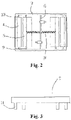
- a mobile car sheave shield which, as shown in Fig. 1 and Fig. 2 , comprises a static shield part 2 which covers outside of car sheave 1; an opening is arranged on the upper surface of the static shield part, and a dynamic shield part is arranged in the opening.
- the dynamic shield part comprises a shield bracket 3 which is a square block structure; a support frame 6 is arranged on the central axis of the shield bracket to divide the shield bracket into a left side and a right side, and an inner side mobile shield 5 and an outer side mobile shield 4 are respectively arranged on each side from inside to outside. Both the inner side mobile shield and the outer side mobile shield are slidingly connected on the shield bracket; guide grooves 12 are respectively arranged on the inner sides of edge frames in a length direction of the shield bracket, and slide bars 10 are arranged at two ends of the inner side mobile shield and the outer side mobile shield; the front ends of the slide bars are embedded in the guide grooves.
- a connecting rod 9 is connected between the inner side mobile shield and the outer side mobile shield, thus synchronously connecting the inner side mobile shield and the outer side mobile shield.
- claws 11 are respectively arranged at two ends of the connecting rod; the claw at one end of the connecting rod is fastened on the slide bar of the inner side mobile shield and the claw at the other end of the connecting rod is fastened on the slide bar of the outer side mobile shield.
- a clearance is formed between the inner side mobile shield and the outer side mobile shield, and the traction rope 18 runs through the clearance.
- Two electric contact switches 7 facing opposite directions are arranged on the support frame, and springs 8 are respectively arranged on two sides of the support frame; the front ends of the springs are connected to the inner side mobile shield on this side.
- both the inner side mobile shield 5 and the outer side mobile shield 4 are provided with upper shield plates 13 on the upper side and lower shield plates 14 on the lower sides; the two upper shield plates are relatively parallel and the two lower shield plates are oppositely parallel; the outer side mobile shield is a structure which is inclined inwards.
- Fixed roller mechanisms are respectively arranged in the middles of opposite surfaces of the inner side mobile shield and the outer side mobile shield.
- Each fixed roller mechanism comprises a shaft base on either inner side mobile shield or outer side mobile shield; a rolling shaft 15 is arranged on the shaft base; a bearing 16 is fixed on the rolling shaft; a roller 17 is fixed on the bearing, and the front end of the roller is exposed out of the front end of the upper shield plate.
Landscapes
- Lift-Guide Devices, And Elevator Ropes And Cables (AREA)
- Cage And Drive Apparatuses For Elevators (AREA)
Claims (7)
- Mobiles Kabinenlaufrollenschild für ein V-förmiges Antriebssystem eines Aufzugsystem, wobei das mobile Kabinenlaufrollenschild Folgendes umfasst:ein statisches Schildteil (2), welcher dazu geeignet ist, eine Kabinenlaufrolle (1) zu umhüllen, wobei eine Öffnung auf einer oberen Fläche des statischen Schildteils gebildet ist; undein dynamisches Schildteil, wobei das dynamische Schildteil auf der Öffnung angeordnet ist; das dynamische Schildteil eine Schildhalterung (3) umfasst; ein mobiles Schild (4) einer Innenseite und ein mobiles Schild (5) einer Außenseite, welche synchron verbunden sind, entsprechend auf zwei Seiten einer zentralen Achse der Schildhalterung von Innen nach Außen angeordnet sind; das mobile Schild der Außenseite und das mobile Schild der Innenseite verschiebbar an der Schildhalterung verbunden sind; eine Kerbe zwischen dem mobilen Schild der Innenseite und dem mobilen Schild der Außenseite gebildet ist und dazu geeignet ist, so angeordnet zu werden, dass ein Antriebsseil durch die Kerbe verläuft.
- Mobiles Kabinenlaufrollenschild nach Anspruch 1, welches dadurch gekennzeichnet ist, dass die Schildhalterung (3) in einem quadratischen Block präsentiert ist; Führungsrillen (12) an den Innenseiten von Kantenrahmen in einer Längsrichtung der Schildhalterung entsprechend gebildet sind; Schiebebalken (10) an zwei Enden des mobilen Schilds (4) der Außenseite und des mobilen Schilds (5) der Innenseite entsprechend angeordnet sind, und wobei die vorderen Enden der Schiebebalken in die Führungsrillen eingebettet sind.
- Mobiles Kabinenlaufrollenschild 1 oder 2, welches dadurch gekennzeichnet ist, dass ein Stützrahmen (6) auf einer mittleren Achse der Schildhalterung angeordnet ist; zwei elektrische Kontaktschalter (7), welche in entgegengesetzte Richtungen zeigen, auf dem Stützrahmen angeordnet sind, und Federn (8) an zwei Seiten des Stützrahmen entsprechend angeordnet sind; wobei die vorderen Enden der Federn auf dieser Seite mit dem mobilen Schild der Innenseite verbunden sind.
- Mobiles Kabinenlaufrollenschild nach einem der vorstehenden Ansprüche, welches dadurch gekennzeichnet ist, dass eine Verbindungsstange (9) zwischen dem mobilen Schild (4) der Innenseite und dem mobilen Schild (5) der Außenseite (5) angeordnet ist; Krallen (11) an zwei Enden der Verbindungsstange entsprechend angeordnet sind; die Kralle an einem Ende der Verbindungsstange an einem Schiebebalken (10) des mobilen Schilds der Innenseite befestigt ist und die Kralle an dem anderen Ende der Verbindungsstange an einem Schiebebalken des mobilen Schilds der Außenseite befestigt ist.
- Mobiles Kabinenlaufrollenschild nach einem der vorstehenden Ansprüche, welches dadurch gekennzeichnet ist, dass sowohl das mobile Schild (5) der Innenseite als auch das mobile Schild (4) der Außenseite mit oberen Schildplatten (13) auf der oberen Seite und unteren Schildplatten (14) auf den unteren Seiten bereitgestellt sind; die zwei oberen Schildplatten relativ parallel sind und die zwei unteren Schildplatten entgegengesetzt parallel sind, und feste Rollenmechanismen in der Mitte von entgegengesetzten Flächen des mobilen Schilds der Innenseite und des mobilen Schilds der Außenseite angeordnet sind.
- Mobiles Kabinenlaufrollenschild nach Anspruch 5, welches dadurch gekennzeichnet ist, dass der feste Rollenmechanismus eine Wellenbasis auf dem mobilen Schild der Innenseite oder dem mobilen Schild der Außenseite umfasst; eine rollende Welle (15) auf der Wellenbasis angeordnet ist; ein Lager (16) auf der rollenden Welle befestigt ist; eine Rolle (17) auf dem Lager befestigt ist und das vordere Ende der Rolle aus dem vorderen Ende der oberen Schildplatte herausschaut.
- Mobiles Kabinenlaufrollenschild nach Anspruch 5 oder 6, welches dadurch gekennzeichnet ist, dass das mobile Schild (4) der Außenseite eine Struktur ist, welche nach Innen geneigt ist.
Applications Claiming Priority (2)
| Application Number | Priority Date | Filing Date | Title |
|---|---|---|---|
| CN201310755224.9A CN103991779B (zh) | 2013-12-31 | 2013-12-31 | 一种移动式轿顶轮防护罩 |
| PCT/US2014/072519 WO2015103117A1 (en) | 2013-12-31 | 2014-12-29 | A mobile car sheave shield |
Publications (2)
| Publication Number | Publication Date |
|---|---|
| EP3089932A1 EP3089932A1 (de) | 2016-11-09 |
| EP3089932B1 true EP3089932B1 (de) | 2022-04-06 |
Family
ID=51306166
Family Applications (1)
| Application Number | Title | Priority Date | Filing Date |
|---|---|---|---|
| EP14824332.2A Not-in-force EP3089932B1 (de) | 2013-12-31 | 2014-12-29 | Mobile autoscheibenabschirmung |
Country Status (4)
| Country | Link |
|---|---|
| US (2) | US20160325963A1 (de) |
| EP (1) | EP3089932B1 (de) |
| CN (1) | CN103991779B (de) |
| WO (1) | WO2015103117A1 (de) |
Families Citing this family (3)
| Publication number | Priority date | Publication date | Assignee | Title |
|---|---|---|---|---|
| AU2017289215B2 (en) * | 2016-06-30 | 2020-04-30 | Inventio Ag | Elevator system in the form of a climbing elevator system, comprising a specifically formed protective roof |
| CN106927326A (zh) * | 2017-03-24 | 2017-07-07 | 江苏利德尔塑化科技股份有限公司 | 一种用于机房钢丝绳的防护罩组件 |
| CN108946386B (zh) * | 2018-07-27 | 2023-12-05 | 天津市奥瑞克电梯有限公司 | 轿底返绳轮护罩 |
Citations (1)
| Publication number | Priority date | Publication date | Assignee | Title |
|---|---|---|---|---|
| EP1364905A1 (de) * | 2002-05-22 | 2003-11-26 | Inventio Ag | Träger für Aufzugskabine |
Family Cites Families (12)
| Publication number | Priority date | Publication date | Assignee | Title |
|---|---|---|---|---|
| GB122651A (en) | 1918-01-21 | 1919-04-03 | Pieter Cato Mueller | Machine for Closing Partly Filled Bags. |
| JPH04179693A (ja) * | 1990-11-14 | 1992-06-26 | Toshiba Corp | エスカレータの集塵装置 |
| US6202359B1 (en) * | 1998-12-18 | 2001-03-20 | Don Reed | Under floor storage system for building |
| ES2382656T3 (es) * | 2003-01-31 | 2012-06-12 | Otis Elevator Company | Soporte integrado para máquina de ascensor, poleas y terminaciones |
| CN2858484Y (zh) * | 2005-12-19 | 2007-01-17 | 上海烟草(集团)公司 | 无动力装载防尘装置 |
| CN201031510Y (zh) * | 2007-03-29 | 2008-03-05 | 胡志成 | 落地式压升伸缩塑钢车库 |
| JP5105512B2 (ja) * | 2007-05-21 | 2012-12-26 | 東芝エレベータ株式会社 | エレベーターのシーブ支持装置 |
| EP2361211B1 (de) * | 2008-12-05 | 2013-10-09 | Otis Elevator Company | Aufzugssystem mit auf einem aufzugsmaschinenträger gestützter steuerelektronik |
| CN202116133U (zh) * | 2011-06-16 | 2012-01-18 | 吴江市德菱电梯配套有限公司 | 一种电梯轿顶减震轮 |
| JP5805212B2 (ja) * | 2011-12-07 | 2015-11-04 | 三菱電機株式会社 | エレベータ装置 |
| CN202542641U (zh) * | 2012-03-20 | 2012-11-21 | 希姆斯电梯(中国)有限公司 | 一种电梯轿顶轮装置 |
| CN203333116U (zh) * | 2013-07-15 | 2013-12-11 | 吴江市聚力机械有限公司 | 稳固易调型电梯对重装置 |
-
2013
- 2013-12-31 CN CN201310755224.9A patent/CN103991779B/zh active Active
- 2013-12-31 US US15/108,890 patent/US20160325963A1/en active Granted
-
2014
- 2014-12-29 US US15/108,890 patent/US10221041B2/en active Active
- 2014-12-29 EP EP14824332.2A patent/EP3089932B1/de not_active Not-in-force
- 2014-12-29 WO PCT/US2014/072519 patent/WO2015103117A1/en not_active Ceased
Patent Citations (1)
| Publication number | Priority date | Publication date | Assignee | Title |
|---|---|---|---|---|
| EP1364905A1 (de) * | 2002-05-22 | 2003-11-26 | Inventio Ag | Träger für Aufzugskabine |
Also Published As
| Publication number | Publication date |
|---|---|
| WO2015103117A1 (en) | 2015-07-09 |
| EP3089932A1 (de) | 2016-11-09 |
| CN103991779B (zh) | 2016-03-09 |
| CN103991779A (zh) | 2014-08-20 |
| US10221041B2 (en) | 2019-03-05 |
| US20160325963A1 (en) | 2016-11-10 |
Similar Documents
| Publication | Publication Date | Title |
|---|---|---|
| EP2673232B1 (de) | Aufzugsregler mit zwei auslösungsmechanismen auf separaten scheiben | |
| US10150648B2 (en) | Tie-down device for compensation sheave, compensation sheave and elevator | |
| US11261055B2 (en) | Elevator emergency stop systems | |
| EP3089932B1 (de) | Mobile autoscheibenabschirmung | |
| CN104724565A (zh) | 带触发机构的电梯制停装置 | |
| JP2014015275A (ja) | エレベータ装置 | |
| EP4077191B1 (de) | Führungsanlage für eine aufzugskabine und aufzugssystem | |
| US10745246B2 (en) | Elevator system | |
| EP3431432B1 (de) | Sicherheitsvorrichtung, sicherheitssystem für aufzüge und aufzugssystem | |
| US20190177124A1 (en) | Housing assembly for a safety actuation device | |
| CN109693987B (zh) | 电梯双向安全制动装置 | |
| US5195616A (en) | One to two stroke roped elevator pit buffers | |
| KR100889280B1 (ko) | 엘리베이터의 로프 제동장치 | |
| WO2017017488A1 (en) | Safety block for elevator | |
| AU2003267718A1 (en) | Safety device for maintenance personnel on a car roof | |
| CN111392542A (zh) | 一种双向安全钳 | |
| EP3380425B1 (de) | Maschinenmontagestruktur für ein aufzugssystem | |
| CN204416834U (zh) | 一种建筑升降机用保护机构 | |
| EP3328773B1 (de) | Absorber für schiene eines aufzugssystems | |
| JP2015168571A (ja) | エレベータ装置 | |
| CN105858396A (zh) | 一种防止电梯轿厢意外移动的装置 | |
| CN214828195U (zh) | 一种轿顶轮防钢丝绳脱槽挡绳杆组件 | |
| CN214879407U (zh) | 一种带挡圈的电梯曳引机曳引轮 | |
| JP2005170573A (ja) | エレベータの作業保護装置 | |
| JP2018203411A (ja) | ガバナ装置及びエレベーター |
Legal Events
| Date | Code | Title | Description |
|---|---|---|---|
| PUAI | Public reference made under article 153(3) epc to a published international application that has entered the european phase |
Free format text: ORIGINAL CODE: 0009012 |
|
| 17P | Request for examination filed |
Effective date: 20160801 |
|
| AK | Designated contracting states |
Kind code of ref document: A1 Designated state(s): AL AT BE BG CH CY CZ DE DK EE ES FI FR GB GR HR HU IE IS IT LI LT LU LV MC MK MT NL NO PL PT RO RS SE SI SK SM TR |
|
| AX | Request for extension of the european patent |
Extension state: BA ME |
|
| DAX | Request for extension of the european patent (deleted) | ||
| RAP1 | Party data changed (applicant data changed or rights of an application transferred) |
Owner name: OTIS ELEVATOR COMPANY |
|
| STAA | Information on the status of an ep patent application or granted ep patent |
Free format text: STATUS: EXAMINATION IS IN PROGRESS |
|
| 17Q | First examination report despatched |
Effective date: 20191205 |
|
| GRAP | Despatch of communication of intention to grant a patent |
Free format text: ORIGINAL CODE: EPIDOSNIGR1 |
|
| STAA | Information on the status of an ep patent application or granted ep patent |
Free format text: STATUS: GRANT OF PATENT IS INTENDED |
|
| INTG | Intention to grant announced |
Effective date: 20211117 |
|
| GRAS | Grant fee paid |
Free format text: ORIGINAL CODE: EPIDOSNIGR3 |
|
| GRAA | (expected) grant |
Free format text: ORIGINAL CODE: 0009210 |
|
| STAA | Information on the status of an ep patent application or granted ep patent |
Free format text: STATUS: THE PATENT HAS BEEN GRANTED |
|
| AK | Designated contracting states |
Kind code of ref document: B1 Designated state(s): AL AT BE BG CH CY CZ DE DK EE ES FI FR GB GR HR HU IE IS IT LI LT LU LV MC MK MT NL NO PL PT RO RS SE SI SK SM TR |
|
| REG | Reference to a national code |
Ref country code: GB Ref legal event code: FG4D |
|
| REG | Reference to a national code |
Ref country code: CH Ref legal event code: EP |
|
| REG | Reference to a national code |
Ref country code: AT Ref legal event code: REF Ref document number: 1481180 Country of ref document: AT Kind code of ref document: T Effective date: 20220415 |
|
| REG | Reference to a national code |
Ref country code: IE Ref legal event code: FG4D |
|
| REG | Reference to a national code |
Ref country code: DE Ref legal event code: R096 Ref document number: 602014083148 Country of ref document: DE |
|
| REG | Reference to a national code |
Ref country code: LT Ref legal event code: MG9D |
|
| REG | Reference to a national code |
Ref country code: NL Ref legal event code: MP Effective date: 20220406 |
|
| REG | Reference to a national code |
Ref country code: AT Ref legal event code: MK05 Ref document number: 1481180 Country of ref document: AT Kind code of ref document: T Effective date: 20220406 |
|
| PG25 | Lapsed in a contracting state [announced via postgrant information from national office to epo] |
Ref country code: NL Free format text: LAPSE BECAUSE OF FAILURE TO SUBMIT A TRANSLATION OF THE DESCRIPTION OR TO PAY THE FEE WITHIN THE PRESCRIBED TIME-LIMIT Effective date: 20220406 |
|
| PG25 | Lapsed in a contracting state [announced via postgrant information from national office to epo] |
Ref country code: SE Free format text: LAPSE BECAUSE OF FAILURE TO SUBMIT A TRANSLATION OF THE DESCRIPTION OR TO PAY THE FEE WITHIN THE PRESCRIBED TIME-LIMIT Effective date: 20220406 Ref country code: PT Free format text: LAPSE BECAUSE OF FAILURE TO SUBMIT A TRANSLATION OF THE DESCRIPTION OR TO PAY THE FEE WITHIN THE PRESCRIBED TIME-LIMIT Effective date: 20220808 Ref country code: NO Free format text: LAPSE BECAUSE OF FAILURE TO SUBMIT A TRANSLATION OF THE DESCRIPTION OR TO PAY THE FEE WITHIN THE PRESCRIBED TIME-LIMIT Effective date: 20220706 Ref country code: LT Free format text: LAPSE BECAUSE OF FAILURE TO SUBMIT A TRANSLATION OF THE DESCRIPTION OR TO PAY THE FEE WITHIN THE PRESCRIBED TIME-LIMIT Effective date: 20220406 Ref country code: HR Free format text: LAPSE BECAUSE OF FAILURE TO SUBMIT A TRANSLATION OF THE DESCRIPTION OR TO PAY THE FEE WITHIN THE PRESCRIBED TIME-LIMIT Effective date: 20220406 Ref country code: GR Free format text: LAPSE BECAUSE OF FAILURE TO SUBMIT A TRANSLATION OF THE DESCRIPTION OR TO PAY THE FEE WITHIN THE PRESCRIBED TIME-LIMIT Effective date: 20220707 Ref country code: FI Free format text: LAPSE BECAUSE OF FAILURE TO SUBMIT A TRANSLATION OF THE DESCRIPTION OR TO PAY THE FEE WITHIN THE PRESCRIBED TIME-LIMIT Effective date: 20220406 Ref country code: ES Free format text: LAPSE BECAUSE OF FAILURE TO SUBMIT A TRANSLATION OF THE DESCRIPTION OR TO PAY THE FEE WITHIN THE PRESCRIBED TIME-LIMIT Effective date: 20220406 Ref country code: BG Free format text: LAPSE BECAUSE OF FAILURE TO SUBMIT A TRANSLATION OF THE DESCRIPTION OR TO PAY THE FEE WITHIN THE PRESCRIBED TIME-LIMIT Effective date: 20220706 Ref country code: AT Free format text: LAPSE BECAUSE OF FAILURE TO SUBMIT A TRANSLATION OF THE DESCRIPTION OR TO PAY THE FEE WITHIN THE PRESCRIBED TIME-LIMIT Effective date: 20220406 |
|
| PG25 | Lapsed in a contracting state [announced via postgrant information from national office to epo] |
Ref country code: RS Free format text: LAPSE BECAUSE OF FAILURE TO SUBMIT A TRANSLATION OF THE DESCRIPTION OR TO PAY THE FEE WITHIN THE PRESCRIBED TIME-LIMIT Effective date: 20220406 Ref country code: PL Free format text: LAPSE BECAUSE OF FAILURE TO SUBMIT A TRANSLATION OF THE DESCRIPTION OR TO PAY THE FEE WITHIN THE PRESCRIBED TIME-LIMIT Effective date: 20220406 Ref country code: LV Free format text: LAPSE BECAUSE OF FAILURE TO SUBMIT A TRANSLATION OF THE DESCRIPTION OR TO PAY THE FEE WITHIN THE PRESCRIBED TIME-LIMIT Effective date: 20220406 Ref country code: IS Free format text: LAPSE BECAUSE OF FAILURE TO SUBMIT A TRANSLATION OF THE DESCRIPTION OR TO PAY THE FEE WITHIN THE PRESCRIBED TIME-LIMIT Effective date: 20220806 |
|
| REG | Reference to a national code |
Ref country code: DE Ref legal event code: R097 Ref document number: 602014083148 Country of ref document: DE |
|
| PG25 | Lapsed in a contracting state [announced via postgrant information from national office to epo] |
Ref country code: SM Free format text: LAPSE BECAUSE OF FAILURE TO SUBMIT A TRANSLATION OF THE DESCRIPTION OR TO PAY THE FEE WITHIN THE PRESCRIBED TIME-LIMIT Effective date: 20220406 Ref country code: SK Free format text: LAPSE BECAUSE OF FAILURE TO SUBMIT A TRANSLATION OF THE DESCRIPTION OR TO PAY THE FEE WITHIN THE PRESCRIBED TIME-LIMIT Effective date: 20220406 Ref country code: RO Free format text: LAPSE BECAUSE OF FAILURE TO SUBMIT A TRANSLATION OF THE DESCRIPTION OR TO PAY THE FEE WITHIN THE PRESCRIBED TIME-LIMIT Effective date: 20220406 Ref country code: EE Free format text: LAPSE BECAUSE OF FAILURE TO SUBMIT A TRANSLATION OF THE DESCRIPTION OR TO PAY THE FEE WITHIN THE PRESCRIBED TIME-LIMIT Effective date: 20220406 Ref country code: DK Free format text: LAPSE BECAUSE OF FAILURE TO SUBMIT A TRANSLATION OF THE DESCRIPTION OR TO PAY THE FEE WITHIN THE PRESCRIBED TIME-LIMIT Effective date: 20220406 Ref country code: CZ Free format text: LAPSE BECAUSE OF FAILURE TO SUBMIT A TRANSLATION OF THE DESCRIPTION OR TO PAY THE FEE WITHIN THE PRESCRIBED TIME-LIMIT Effective date: 20220406 |
|
| PLBE | No opposition filed within time limit |
Free format text: ORIGINAL CODE: 0009261 |
|
| STAA | Information on the status of an ep patent application or granted ep patent |
Free format text: STATUS: NO OPPOSITION FILED WITHIN TIME LIMIT |
|
| 26N | No opposition filed |
Effective date: 20230110 |
|
| PG25 | Lapsed in a contracting state [announced via postgrant information from national office to epo] |
Ref country code: AL Free format text: LAPSE BECAUSE OF FAILURE TO SUBMIT A TRANSLATION OF THE DESCRIPTION OR TO PAY THE FEE WITHIN THE PRESCRIBED TIME-LIMIT Effective date: 20220406 |
|
| PG25 | Lapsed in a contracting state [announced via postgrant information from national office to epo] |
Ref country code: SI Free format text: LAPSE BECAUSE OF FAILURE TO SUBMIT A TRANSLATION OF THE DESCRIPTION OR TO PAY THE FEE WITHIN THE PRESCRIBED TIME-LIMIT Effective date: 20220406 |
|
| REG | Reference to a national code |
Ref country code: CH Ref legal event code: PL |
|
| REG | Reference to a national code |
Ref country code: BE Ref legal event code: MM Effective date: 20221231 |
|
| PG25 | Lapsed in a contracting state [announced via postgrant information from national office to epo] |
Ref country code: LU Free format text: LAPSE BECAUSE OF NON-PAYMENT OF DUE FEES Effective date: 20221229 |
|
| PG25 | Lapsed in a contracting state [announced via postgrant information from national office to epo] |
Ref country code: LI Free format text: LAPSE BECAUSE OF NON-PAYMENT OF DUE FEES Effective date: 20221231 Ref country code: IE Free format text: LAPSE BECAUSE OF NON-PAYMENT OF DUE FEES Effective date: 20221229 Ref country code: CH Free format text: LAPSE BECAUSE OF NON-PAYMENT OF DUE FEES Effective date: 20221231 |
|
| PG25 | Lapsed in a contracting state [announced via postgrant information from national office to epo] |
Ref country code: BE Free format text: LAPSE BECAUSE OF NON-PAYMENT OF DUE FEES Effective date: 20221231 |
|
| PGFP | Annual fee paid to national office [announced via postgrant information from national office to epo] |
Ref country code: GB Payment date: 20231121 Year of fee payment: 10 |
|
| PG25 | Lapsed in a contracting state [announced via postgrant information from national office to epo] |
Ref country code: IT Free format text: LAPSE BECAUSE OF FAILURE TO SUBMIT A TRANSLATION OF THE DESCRIPTION OR TO PAY THE FEE WITHIN THE PRESCRIBED TIME-LIMIT Effective date: 20220406 |
|
| PGFP | Annual fee paid to national office [announced via postgrant information from national office to epo] |
Ref country code: FR Payment date: 20231122 Year of fee payment: 10 Ref country code: DE Payment date: 20231121 Year of fee payment: 10 |
|
| PG25 | Lapsed in a contracting state [announced via postgrant information from national office to epo] |
Ref country code: HU Free format text: LAPSE BECAUSE OF FAILURE TO SUBMIT A TRANSLATION OF THE DESCRIPTION OR TO PAY THE FEE WITHIN THE PRESCRIBED TIME-LIMIT; INVALID AB INITIO Effective date: 20141229 |
|
| PG25 | Lapsed in a contracting state [announced via postgrant information from national office to epo] |
Ref country code: CY Free format text: LAPSE BECAUSE OF FAILURE TO SUBMIT A TRANSLATION OF THE DESCRIPTION OR TO PAY THE FEE WITHIN THE PRESCRIBED TIME-LIMIT Effective date: 20220406 |
|
| PG25 | Lapsed in a contracting state [announced via postgrant information from national office to epo] |
Ref country code: MK Free format text: LAPSE BECAUSE OF FAILURE TO SUBMIT A TRANSLATION OF THE DESCRIPTION OR TO PAY THE FEE WITHIN THE PRESCRIBED TIME-LIMIT Effective date: 20220406 |
|
| PG25 | Lapsed in a contracting state [announced via postgrant information from national office to epo] |
Ref country code: MC Free format text: LAPSE BECAUSE OF FAILURE TO SUBMIT A TRANSLATION OF THE DESCRIPTION OR TO PAY THE FEE WITHIN THE PRESCRIBED TIME-LIMIT Effective date: 20220406 |
|
| PG25 | Lapsed in a contracting state [announced via postgrant information from national office to epo] |
Ref country code: TR Free format text: LAPSE BECAUSE OF FAILURE TO SUBMIT A TRANSLATION OF THE DESCRIPTION OR TO PAY THE FEE WITHIN THE PRESCRIBED TIME-LIMIT Effective date: 20220406 Ref country code: MC Free format text: LAPSE BECAUSE OF FAILURE TO SUBMIT A TRANSLATION OF THE DESCRIPTION OR TO PAY THE FEE WITHIN THE PRESCRIBED TIME-LIMIT Effective date: 20220406 |
|
| PG25 | Lapsed in a contracting state [announced via postgrant information from national office to epo] |
Ref country code: MT Free format text: LAPSE BECAUSE OF FAILURE TO SUBMIT A TRANSLATION OF THE DESCRIPTION OR TO PAY THE FEE WITHIN THE PRESCRIBED TIME-LIMIT Effective date: 20220406 |
|
| PG25 | Lapsed in a contracting state [announced via postgrant information from national office to epo] |
Ref country code: BG Free format text: LAPSE BECAUSE OF FAILURE TO SUBMIT A TRANSLATION OF THE DESCRIPTION OR TO PAY THE FEE WITHIN THE PRESCRIBED TIME-LIMIT Effective date: 20220406 |
|
| PG25 | Lapsed in a contracting state [announced via postgrant information from national office to epo] |
Ref country code: BG Free format text: LAPSE BECAUSE OF FAILURE TO SUBMIT A TRANSLATION OF THE DESCRIPTION OR TO PAY THE FEE WITHIN THE PRESCRIBED TIME-LIMIT Effective date: 20220406 |
|
| REG | Reference to a national code |
Ref country code: DE Ref legal event code: R119 Ref document number: 602014083148 Country of ref document: DE |
|
| GBPC | Gb: european patent ceased through non-payment of renewal fee |
Effective date: 20241229 |
|
| PG25 | Lapsed in a contracting state [announced via postgrant information from national office to epo] |
Ref country code: DE Free format text: LAPSE BECAUSE OF NON-PAYMENT OF DUE FEES Effective date: 20250701 |
|
| PG25 | Lapsed in a contracting state [announced via postgrant information from national office to epo] |
Ref country code: GB Free format text: LAPSE BECAUSE OF NON-PAYMENT OF DUE FEES Effective date: 20241229 |
|
| PG25 | Lapsed in a contracting state [announced via postgrant information from national office to epo] |
Ref country code: FR Free format text: LAPSE BECAUSE OF NON-PAYMENT OF DUE FEES Effective date: 20241231 |