EP3090101B1 - Saugsystem zur erzeugung eines saugstromes innerhalb einer saugstromleitung - Google Patents
Saugsystem zur erzeugung eines saugstromes innerhalb einer saugstromleitung Download PDFInfo
- Publication number
- EP3090101B1 EP3090101B1 EP15716725.5A EP15716725A EP3090101B1 EP 3090101 B1 EP3090101 B1 EP 3090101B1 EP 15716725 A EP15716725 A EP 15716725A EP 3090101 B1 EP3090101 B1 EP 3090101B1
- Authority
- EP
- European Patent Office
- Prior art keywords
- suction
- fan
- internal air
- flow
- suction flow
- Prior art date
- Legal status (The legal status is an assumption and is not a legal conclusion. Google has not performed a legal analysis and makes no representation as to the accuracy of the status listed.)
- Active
Links
Images



Classifications
-
- F—MECHANICAL ENGINEERING; LIGHTING; HEATING; WEAPONS; BLASTING
- F04—POSITIVE - DISPLACEMENT MACHINES FOR LIQUIDS; PUMPS FOR LIQUIDS OR ELASTIC FLUIDS
- F04C—ROTARY-PISTON, OR OSCILLATING-PISTON, POSITIVE-DISPLACEMENT MACHINES FOR LIQUIDS; ROTARY-PISTON, OR OSCILLATING-PISTON, POSITIVE-DISPLACEMENT PUMPS
- F04C13/00—Adaptations of machines or pumps for special use, e.g. for extremely high pressures
- F04C13/001—Pumps for particular liquids
-
- E—FIXED CONSTRUCTIONS
- E02—HYDRAULIC ENGINEERING; FOUNDATIONS; SOIL SHIFTING
- E02F—DREDGING; SOIL-SHIFTING
- E02F3/00—Dredgers; Soil-shifting machines
- E02F3/04—Dredgers; Soil-shifting machines mechanically-driven
- E02F3/88—Dredgers; Soil-shifting machines mechanically-driven with arrangements acting by a sucking or forcing effect, e.g. suction dredgers
- E02F3/8816—Mobile land installations
-
- E—FIXED CONSTRUCTIONS
- E02—HYDRAULIC ENGINEERING; FOUNDATIONS; SOIL SHIFTING
- E02F—DREDGING; SOIL-SHIFTING
- E02F3/00—Dredgers; Soil-shifting machines
- E02F3/04—Dredgers; Soil-shifting machines mechanically-driven
- E02F3/88—Dredgers; Soil-shifting machines mechanically-driven with arrangements acting by a sucking or forcing effect, e.g. suction dredgers
- E02F3/8891—Dredgers; Soil-shifting machines mechanically-driven with arrangements acting by a sucking or forcing effect, e.g. suction dredgers wherein at least a part of the soil-shifting equipment is handheld
-
- E—FIXED CONSTRUCTIONS
- E02—HYDRAULIC ENGINEERING; FOUNDATIONS; SOIL SHIFTING
- E02F—DREDGING; SOIL-SHIFTING
- E02F3/00—Dredgers; Soil-shifting machines
- E02F3/04—Dredgers; Soil-shifting machines mechanically-driven
- E02F3/88—Dredgers; Soil-shifting machines mechanically-driven with arrangements acting by a sucking or forcing effect, e.g. suction dredgers
- E02F3/90—Component parts, e.g. arrangement or adaptation of pumps
-
- F—MECHANICAL ENGINEERING; LIGHTING; HEATING; WEAPONS; BLASTING
- F04—POSITIVE - DISPLACEMENT MACHINES FOR LIQUIDS; PUMPS FOR LIQUIDS OR ELASTIC FLUIDS
- F04C—ROTARY-PISTON, OR OSCILLATING-PISTON, POSITIVE-DISPLACEMENT MACHINES FOR LIQUIDS; ROTARY-PISTON, OR OSCILLATING-PISTON, POSITIVE-DISPLACEMENT PUMPS
- F04C11/00—Combinations of two or more machines or pumps, each being of rotary-piston or oscillating-piston type; Pumping installations
- F04C11/005—Combinations of two or more machines or pumps, each being of rotary-piston or oscillating-piston type; Pumping installations of dissimilar working principle
-
- F—MECHANICAL ENGINEERING; LIGHTING; HEATING; WEAPONS; BLASTING
- F04—POSITIVE - DISPLACEMENT MACHINES FOR LIQUIDS; PUMPS FOR LIQUIDS OR ELASTIC FLUIDS
- F04D—NON-POSITIVE-DISPLACEMENT PUMPS
- F04D23/00—Other rotary non-positive-displacement pumps
- F04D23/001—Pumps adapted for conveying materials or for handling specific elastic fluids
- F04D23/003—Pumps adapted for conveying materials or for handling specific elastic fluids of radial-flow type
-
- F—MECHANICAL ENGINEERING; LIGHTING; HEATING; WEAPONS; BLASTING
- F04—POSITIVE - DISPLACEMENT MACHINES FOR LIQUIDS; PUMPS FOR LIQUIDS OR ELASTIC FLUIDS
- F04D—NON-POSITIVE-DISPLACEMENT PUMPS
- F04D25/00—Pumping installations or systems
- F04D25/16—Combinations of two or more pumps ; Producing two or more separate gas flows
Definitions
- the invention relates to a suction system for generating a suction flow within a Saugstrom für, in particular for use in a suction conveyor.
- Suction systems have been known and used worldwide for many years. Generally, these can be classified into two groups. The first group creates a negative pressure and thus an air flow by means of pumps. Depending on the application, centrifugal piston pumps, rotary lobe pumps or Roots blowers are used in this group. Roots blowers are rotary lobe blowers without internal compression which resemble gear and rotary vane pumps. All these pump variants share similar characteristics. They generate high to very high differential pressures, but the volume flow is comparatively low.
- suction systems based on pumps also have the property that the necessary power requirement increases when the air flow stops, up to a maximum. Due to their physical properties, pump systems are particularly suitable for so-called thick flow conveying. This means that material such as water and sludge can be conveyed as full volume flow without air fractions.
- the second group of suction systems works on the basis of fans. Fans are capable of producing large airflows but with a comparatively low differential pressure. In order to increase the differential pressures in fan systems, two or more fans have been connected in series with one another in terms of ventilation technology in recent years. Such a solution is for example from the EP 2 647 770 A1 or the DE 20 2012 101 190 U1 known. However, this solution requires very high drive power for the fan systems.
- a percentage increase in differential pressure requires a percent quadratic increase in drive power.
- the necessary drive power is inversely related to the pumping system in relation to the pumping system. The lower the flow rate, the lower the power requirement for the drive.
- fan systems are suitable for the promotion of thin-flow. This means, the fast-flowing air flows are the transport medium; the actual material to be transported is low in relation to the volume of the transport medium. In fan-based suction systems, therefore, the carrying capacity of rapidly flowing air flows is utilized.
- thin-flow conveying all media can be transported, solid particles up to a size which is close to the inner diameter of the suction line.
- the invention has for its object to combine the advantageous properties of both suction systems together.
- a suction system is to be proposed, which is suitable for both the Dickstrom portion and for Dünnstrom potion.
- the Dünnstrom cramp should be energy efficient possible.
- the solution of the problem is given in the independent claim.
- Advantageous embodiments and uses are shown in the dependent claims.
- the object is achieved in a suction system, consisting of a Saugstromtechnisch with integrated separation, a Saugstrom generation and an exhaust air duct.
- a separator in which material contained in a suction flow, is discharged from the suction flow connected.
- a suction system according to the invention is characterized in that a fan system comprising one or more fans and a pump system comprising one or more pumps are provided as suction power generation for generating the suction flow and are connected in series or in parallel to generate the suction flow.
- the invention described below describes a suction system which combines the advantages of fan and pump systems.
- the suction system to be developed is suitable for both heavy-flow conveying and thin-flow conveying.
- an increase in performance is achieved in the Dünnstrom employed.
- the core of the invention is the air-technical interconnection of one or more fans with one or more pumps, all for common production of the suction flow are arranged in a common Saugstrom für.
- a separator for depositing the sucked material and at least one common filter system of at least one filter is arranged.
- the outputs of the respective fans and pumps are optionally delivered to the atmosphere via common or separate lines (here also: exhaust air ducts).
- the exhaust air of the fan system and the pump system preferably passes through a silencer in the exhaust duct before it is discharged to the environment.
- the silencer serves to reduce the noise emission of the suction system.
- the Saugstromtechnisch may consist of solid or flexible materials.
- Media material are, for example, bulk solids, mixtures of solids and liquids, eg. As mud, liquids and soil.
- the separator is preferably formed by a chamber or a (separation) container, in which the suction flow flows. Due to a larger flow cross section of the separator relative to the suction flow line, the flow velocity of the suction flow decreases. If the suction flow is filled with material, this drops out of the suction flow due to the reduced flow velocity and the associated reduced transport capacity of the suction flow.
- the separator can also be designed as a cyclone separator. For the maintenance and low-wear operation of the suction system, it is advantageous if the suction flow line are assigned as a separator of the container for collecting solid components of the suction flow and a filter for fine cleaning of the suction flow. It can also be arranged several filters (filter system).
- the container is preferably tiltable or replaceable in order to be able to empty the container or to provide an empty container when a maximum filling level of the container with material is reached.
- separators with their own discharge option, including permanent removal during the suction process.
- the container is preferably provided with a level detecting device for promoting the material upon reaching a maximum level break up. Particularly in the case of thick flow conveying, it is necessary to terminate the delivery when the maximum level is reached in order to prevent the material from being sucked into the filter system or into the pump system.
- fan system and the pump system are arranged parallel to each other in terms of ventilation, wherein by a shut-off system in front of the fan system caused by the pump system suction via the fan system and against the conveying direction of the fan system is prevented.
- This arrangement variant of fan system and pump system is hereinafter also referred to as parallel connection.
- the fan system and the pump system are pneumatically connected to the separator via a section of the suction flow line.
- the fan system and the pump system can also be pneumatically connected to the separator via separate sections of the suction flow line.
- a parallel connection is achieved in that the fan system within a first internal air duct for guiding a first Operaaugstroms and the pump system within a second internal air duct for guiding a second Operaaugstrom are air-technically parallel to each other, wherein by a shut-off system upstream of the fan system, an intake by the pump system is prevented via the fan system and against a conveying direction of the fan system.
- the fan system and the pump system can be arranged successively in terms of ventilation, wherein the fan system is arranged upstream of the pump system.
- a first internal air duct for supplying a first Operaaugstroms via a shut-off system and subsequently via a silencer to the outside and a second internal air duct for supplying a second Operaaugstrom to the pump system are present, whereby prevented by the shut-off system, a suction of the pump system via the silencer is.
- the fan system is pneumatically connected to the separator via a section of the suction flow line Connection. This arrangement variant of fan system and pump system is hereinafter also referred to as a series circuit or serial circuit.
- a shut-off system can be formed for example by one or more non-return valves.
- the shut-off system has in the interconnection of fan system and pump system, the task to foreclose the fan system in the event of "zero promotion" of the fan system against the pump system and thus ensure that the entire volume flow of the pump system flows through the common Saugstrom für and not contrary to the conveying direction of the Fan system is pulled.
- the shut-off system is mounted in front of the inlet of the fan system.
- the output of the fan system is divided into the first internal air duct for supplying the first partial suction flow to the shut-off system and on to the exhaust air duct and the second internal air duct for supplying the second partial suction flow to the pump system.
- a safety system is installed in front of the pump system to prevent unacceptably high negative pressure values.
- the safety system may, for example, have a vacuum valve.
- the vacuum valve has the task to open a bypass line (bypass) to the ambient air when reaching a maximum allowable negative pressure value and thus to ensure that the entire suction system is charged only up to the designed negative pressure resistance.
- the vacuum valve is installed in the ventilation system before the pump system.
- the first internal air duct is connected to the second internal air duct via an additional third internal air duct in connection with ventilation technology.
- a flow switch for selectively guiding the Operaaugströme within one or more of the internal air ducts is present, whereby an optional generation of the suction flow by parallel or series connection of the pump and fan systems can be realized and a switch between parallel connection and series connection of fan system and pump system can take place.
- the fan system of a suction system can consist either of a fan or of a plurality of fans connected in series. If fans connected in series are used as fan system, this preferably consists either of two fans connected in series or of three fans connected in series. By a series connection of fans, a higher pressure difference of the suction flow can be generated.
- the fan system and / or the pump system can be driven mechanically, electrically, hydraulically and / or pneumatically.
- the drive may be a mechanical drive, for example via shafts and gears, a hydraulic drive, for example by a hydraulic motor, or an electric drive, for example by an electric motor.
- Suction system can advantageously be used in a suction conveyor.
- Suction conveyor systems include both stationary and mobile systems.
- the suction conveyor with the suction system according to the invention can be advantageously used in a suction dredger.
- This can for example be realized by an inventive suction system, which is mounted on a suitable vehicle such as a truck, a rail vehicle or a watercraft. All the possibilities of interconnecting the fan system and the pump system are suitable for thick and thin-flow conveying. The particular type of promotion depends only on the position of the shut-off system and of course on which air flow generators are turned on at all.
- suction system 1 The embodiments of the suction system 1 according to the invention are described below with reference to schematic representations. In this case, like reference numerals designate the same technical elements.
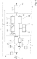
- Fig. 1 schematically shown first embodiment are as essential elements of the suction system 1 according to the invention a Saugstrom Gustav 3 with integrated separator 3.1, a Saugstrom generation 2, consisting of fan systems 2.1 and pump systems 2.2, 2.3 shut-off systems and security systems 2.4, and an exhaust duct 4 with integrated silencer 4.1 available.
- the elements Saugstromtechnisch 3, Saugstrom 2 and exhaust 4 are shown by dotted lines graphically separated according to their functions.
- This type of interconnection of fan and pump systems corresponds to a parallel connection and is suitable for both thin and thick flow promotion.
- a suction flow 7 (symbolized by an arrow) is pneumatically drawn in the suction flow line 3, sucked through the material 6 at one end of the Saugstromtechnisch 3 and in a conveying direction 5 through the Saugstrom effet 3 into the separator 3.1 is transported.
- the suction flow line 3 opens into the separator 3.1, which is formed by a separating vessel 3.1.1 and a filter 3.1.2.
- the velocity of the suction flow 7 drops sharply due to the large cross-section of the separation vessel 3.1.1, whereby the transport capacity of the transport medium also drops.
- the filter 3.1.2 which is downstream of the separating vessel 3.1.1 air-technically, from the suction stream 7.
- the suction flow 7 is divided by the filter 3.1.2 and flows as a first Operaaugstrom 7.1 within a formed by a flow channel first internal air duct 2.6 to the fan system 2.1.
- a second Operaaugstrom 7.2 flows within a second internal air duct 2.7 to the pump system 2.2.
- the first internal air duct 2.6 and the second internal air duct 2.7 are reunited and form an exhaust duct 4.
- the muffler is arranged 4.1, which is flowed through by the reunited suction stream 7, before this in the environment is blown out.
- the exhaust air duct 4 of fan system 2.1 and pump system 2.2 can also be designed separately.
- the fan system 2.1 is preceded by a shut-off system 2.3 in the first internal air duct 2.6, which is formed by a check valve 8 (shown schematically).
- a check valve 8 shown schematically.
- a security system 2.4 is present in terms of ventilation technology upstream of the pump system 2.2, which safety system is realized by a vacuum valve 9 in the first exemplary embodiment shown.
- the suction system 1 is associated with a controller 10, through which a control and regulation of the fan system 2.1 and 2.2 of the pump system is possible.
- the controller 10 may be in further embodiments of the suction system 1 with sensors 11 (only one example shown) in conjunction.
- Sensors 11 may be, for example, level sensors, pressure sensors, speed sensors, speed sensors and / or temperature sensors.
- a suction system 1 is shown schematically, which represents a series connection of fan system 2.1 and pump system 2.2. Also, this embodiment is suitable both for Dickstrom faced and for Dünnstrom faced.
- the ventilator system 2.1 is arranged downstream of the filter 3.1.2 in the suction flow line 3. Only after the fan system 2.1, the Saugstrom effet 3 is divided into the first internal air duct 2.6 and the second internal air duct 2.7. In the first internal air duct 2.6 the shut-off 2.3 is present.
- the pump system 2.2 and the safety system 2.4 are arranged in the second internal air guide 2.7.
- the first partial suction flow 7.1 and the second partial suction flow 7.2 are not reunited and are blown off independently of each other.
- FIG. 3 schematically shows a third embodiment of the suction system 1, in which a change between parallel and series connection of the fan system 2.1 and the pump system 2.2 is made possible by before and after the fan system 2.1 each have a shut-off 2.3, 2.3.1, 2.3.2 and a Flow switch 2.5 are installed.
- a shut-off 2.3, 2.3.1, 2.3.2 and a Flow switch 2.5 are installed in conjunction with the states of the shut-off 2.3 and the flow switch 2.5 both parallel and series connection of the fan system 2.1 and pump system 2.2 can be produced.
- a first shut-off system 2.3.1, the fan system 2.1 and a second shut-off system 2.3.2 are arranged in succession.
- the first shut-off 2.3.1 and the second shut-off 2.3.2 are designed so that they are individually controlled by the controller 10 to close and open.
- an undesired reversal of the suction flow 7 or partial suction flows 7.1, 7.2 can be prevented.
- the safety system 2.4 and the pump system 2.2 are arranged.
- the first and second internal air ducts 2.6, 2.7 are reunited according to the pump system 2.2 and after the second shut-off 2.3.2, so that the first and the second Operaaugstrom 7.1, 7.2 as a reunified suction 7 via the exhaust air duct 4th and the silencer 4.1 is blown into the environment.
- a flow switch 2.5 is arranged in front of the safety system 2.4 in the second internal air guide 2.7, which can be operated in several operating positions.
- the flow switch 2.5 is pneumatically in communication with a third internal air duct 2.8, through which the first and the second internal air duct 2.6, 2.7 can be pneumatically connected with each other.
- the third internal air duct 2.8 is pneumatically connected after the fan system 2.1 pneumatically with the second internal air duct 2.7.
- the first shut-off 2.3.1 fulfills the protective function against an unwanted reversal of the first Operaaugstrom 7.1, as already described above.
- the second shut-off 2.3.2 is open and has no effect. This operating state enables a thick flow delivery when the first shut-off system 2.3.1 is closed and an increased-capacity thin-flow conveyance when the first shut-off system 2.3.1 is open.
- the second operating mode of the flow switch 2.5 closes the second internal air guide 2.7 to the flow switch 2.5 and opens the third internal air guide 2.8.
- the first shut-off 2.3.1 is open and without effect, the second shut-off 2.3.2 is closed when an excessive suction resistance in the Saugstrom Arthur 3 occurs and there is a risk that air is sucked against the conveying direction 5 by the powerful pump system 2.2.
- the suction flow 7 flows through the open first shut-off 2.3.1, further through the first internal air duct 2.6, then through the fan system 2.1 and from there as a first Operaaugstrom 7.1 via the second shut-off 2.3.2 and as a second Operaaugstrom 7.2 by the flow switch 2.5 released third internal air duct 2.8 via the pump system 2.2.
- This operating state represents a series connection of fan system 2.1 and pump system 2.2, with the possibility of thick flow and performance-enhanced Dünnstrom constitu.
- a fourth embodiment according to Fig. 4 is the fan system 2.1 connected via the first internal air duct 2.6 and 3.1.2 the filter with the separating tank 3.1.1.
- the pump system 2.2 is connected via the second internal air guide 2.7 directly to the separating vessel 3.1.1.
- the second internal air guide 2.7 is also associated with a filter 3.1.2 through which the second Operaaugstrom 7.2 is performed.
- This embodiment enables a parallel connection of fan system 2.1 and pump system 2.2.
- This operating state allows for closed shut-off system 2.3 a Dickstrom lacking and open shut-off 2.3 a performance-enhanced Dünnstrom plausible.
- the Fig. 5 shows greatly simplified assembly of the suction system 1 according to the invention on a 2-axis carrier vehicle 12.
- the assembly can also be done on chassis with three or more axles.
- the separating vessel 3.1.1, the filter 3.1.2, the fan system 2.1, the pump system 2.2 and the silencer 4.1 are shown.
- the drive (not shown) of the suction system 1 according to the invention can be carried out both by the engine of the carrier vehicle 12 and by a separate drive motor.
- the drive may be a mechanical drive, for example via shafts and gears, a hydraulic drive, for example by a hydraulic motor, or an electric drive, for example by an electric motor.
- the suction system 1 can both be fixedly mounted on the carrier vehicle 12 and designed as a change unit, which can be removed if necessary from the carrier vehicle 12 and replaced by another unit.
Landscapes
- Engineering & Computer Science (AREA)
- Mechanical Engineering (AREA)
- General Engineering & Computer Science (AREA)
- Mining & Mineral Resources (AREA)
- Civil Engineering (AREA)
- Structural Engineering (AREA)
- Structures Of Non-Positive Displacement Pumps (AREA)
Description
- Die Erfindung betrifft ein Saugsystem zur Erzeugung eines Saugstromes innerhalb einer Saugstromleitung, insbesondere zur Verwendung in einer Saugförderanlage. Saugsysteme sind weltweit seit vielen Jahren bekannt und im Einsatz. Generell können diese in zwei Gruppen klassifiziert werden.
Die erste Gruppe erzeugt einen Unterdruck und somit einen Luftstrom mittels Pumpen. Bei dieser Gruppe kommen je nach Anwendungsfall beispielsweise Kreiselkolbenpumpen, Drehkolbenpumpen oder auch Roots-Gebläse zum Einsatz. Roots-Gebläse sind Drehkolbengebläse ohne innere Verdichtung, die Zahnrad- und Drehschieberpumpen ähneln.
All diesen Pumpenvarianten sind ähnliche Eigenschaften gemeinsam. Sie erzeugen hohe bis sehr hohe Differenzdrücke, wobei der Volumenstrom aber vergleichsweise gering ist. Alle Saugsysteme auf Basis von Pumpen weisen zudem die Eigenschaft auf, dass der notwendige Leistungsbedarf bei stehendem Luftstrom bis zu einem Maximum ansteigt. Aufgrund ihrer physikalischen Eigenschaften sind Pumpensysteme besonders zur sogenannten Dickstromförderung geeignet. Dies bedeutet, dass Material wie Wasser und Schlamm als voller Volumenstrom ohne Luftanteile gefördert werden kann.
Die zweite Gruppe der Saugsysteme arbeitet auf der Basis von Ventilatoren. Ventilatoren sind in der Lage, große Luftströme zu erzeugen, allerdings bei vergleichsweise geringem Differenzdruck. Um die Differenzdrücke bei Ventilatorsystemen zu erhöhen, wurden in den letzten Jahren zwei oder mehrere Ventilatoren lufttechnisch hintereinander geschaltet. Eine solche Lösung ist beispielsweise aus derEP 2 647 770 A1 oder derDE 20 2012 101 190 U1 bekannt. Diese Lösung erfordert allerdings sehr hohe Antriebsleistungen für die Ventilatorsysteme. Eine prozentuale Steigerung des Differenzdruckes erfordert eine prozentuale quadratische Steigerung der Antriebsleistung. Bei Ventilatoren ist die notwendige Antriebsleistung bezogen auf die Fördermenge invers zu den Pumpensystemen. Je geringer die Fördermenge, desto geringer ist auch der Leistungsbedarf zum Antrieb. Aufgrund ihrer physikalischen Eigenschaften sind Ventilatorensysteme zur Dünnstromförderung geeignet. Dies bedeutet, die schnell fließenden Luftströme sind das Transportmedium; das eigentlich zu transportierende Material ist im Verhältnis zum Volumen des Transportmediums gering. Bei Saugsystemen auf Ventilatorbasis wird also die Tragfähigkeit schnell fließender Luftströme genutzt. Mittels Dünnstromförderung ist ein Transport aller Medien möglich, feste Partikel bis zu einer Größe, die nahe dem Innendurchmesser der Saugleitung liegt.
Der Erfindung liegt die Aufgabe zugrunde, die vorteilhaften Eigenschaften beider Saugsysteme miteinander zu kombinieren. Dabei soll ein Saugsystem vorgeschlagen werden, welches sowohl zur Dickstromförderung als auch zur Dünnstromförderung geeignet ist. Die Dünnstromförderung soll dabei energieeffizient möglich sein.
Die Lösung der Aufgabe ist in dem unabhängigen Anspruch angegeben. Vorteilhafte Ausgestaltungen und Verwendungen sind in den abhängigen Ansprüchen aufgezeigt. Die Aufgabe wird in einem Saugsystem, bestehend aus einer Saugstromleitung mit integrierter Abscheidung, einer Saugstromerzeugung sowie einer Abluftführung gelöst. Innerhalb der Saugstromleitung ist nahe der Saugstromerzeugung ein Abscheider, in dem Material, das in einem Saugstrom enthalten ist, aus dem Saugstrom ausgeschieden wird, angeschlossen. Gekennzeichnet ist ein erfindungsgemäßes Saugsystem dadurch, dass ein Ventilatorsystem aus einem oder mehreren Ventilatoren und ein Pumpensystem aus einer oder mehreren Pumpen als Saugstromerzeugung zur Erzeugung des Saugstroms vorhanden sind und zur Erzeugung des Saugstroms in Reihe oder parallel geschaltet werden. Durch die nachfolgend beschriebene Erfindung ist ein Saugsystem beschrieben, welches die Vorteile von Ventilator- und Pumpensystemen vereint. Das zu entwickelnde Saugsystem ist sowohl zur Dickstromförderung als auch zur Dünnstromförderung geeignet. Zusätzlich wird bei der Dünnstromförderung eine Leistungssteigerung erzielt. Bei mobilen Sauganlagen auf LKW-Chassis ist es dabei unbedeutend, ob die notwendige Antriebsenergie des Saugsystems vom Chassismotor oder von einem separaten Motor erzeugt wird.
Kern der Erfindung ist die lufttechnische Zusammenschaltung von einem oder mehreren Ventilatoren mit einer oder mehreren Pumpen, die alle zur gemeinsamen Erzeugung des Saugstroms in einer gemeinsamen Saugstromleitung angeordnet sind. Am Ende eines ersten Bereichs der gemeinsamen Saugstromleitung ist ein Abscheider zur Ablagerung des angesaugten Materials sowie mindestens ein gemeinsames Filtersystem aus mindestens einem Filter angeordnet. Die Ausgänge der jeweiligen Ventilatoren und Pumpen werden wahlweise über gemeinsame oder getrennte Leitungen (hier auch: Abluftführungen) an die Atmosphäre abgegeben. Die Abluft des Ventilatorsystems und des Pumpensystems durchläuft dabei vorzugsweise einen Schalldämpfer in der Abluftführung, ehe sie an die Umgebung abgegeben wird. Der Schalldämpfer dient der Reduzierung der Geräuschemission des Saugsystems. - Die Saugstromleitung kann aus festen oder flexiblen Materialien bestehen.
- Medien (Material) sind beispielsweise Schüttgüter, Mischungen von Festkörpern und Flüssigkeiten, z. B. Schlamm, Flüssigkeiten und Erdreich.
- Der Abscheider ist vorzugsweise durch eine Kammer oder einen (Abscheide-)Behälter gebildet, in die der Saugstrom einströmt. Aufgrund eines größeren Strömungsquerschnitts des Abscheiders gegenüber der Saugstromleitung sinkt die Strömungsgeschwindigkeit des Saugstroms. Ist der Saugstrom mit Material befüllt, fällt dieses aufgrund der verringerten Strömungsgeschwindigkeit und der damit einhergehenden verringerten Transportkapazität des Saugstroms aus dem Saugstrom aus. Der Abscheider kann auch als ein Zyklonabscheider ausgeführt sein. Für den wartungs- und verschleißarmen Betrieb des Saugsystems ist es günstig, wenn der Saugstromleitung als Abscheider der Behälter zum Auffangen von festen Bestandteilen des Saugstromes sowie ein Filter zur Feinreinigung des Saugstroms zugeordnet sind. Es können auch mehrere Filter (Filtersystem) angeordnet sein. Der Behälter ist vorzugsweise kippbar oder austauschbar, um bei Erreichen eines Höchstfüllstandes des Behälters mit Material den Behälter entleeren zu können bzw. einen leeren Behälter zur Verfügung stellen zu können. Es können aber auch Abscheider mit eigener Ausfördermöglichkeit, auch permanenter Ausförderung während des Saugprozesses zum Einsatz kommen.
- Der Behälter ist vorzugsweise mit einer Vorrichtung zur Erfassung des Füllstandes versehen, um eine Förderung des Materials bei Erreichen eines Höchstfüllstandes zu beenden. Insbesondere bei der Dickstromförderung ist ein Beenden der Förderung mit Erreichen des Höchstfüllstandes nötig, um ein Ansaugen des Materials in das Filtersystem beziehungsweise in das Pumpensystem zu verhindern.
- Erfindungsgemäß sind das Ventilatorsystem und das Pumpensystem lufttechnisch parallel zueinander angeordnet, wobei durch ein Absperrsystem vor dem Ventilatorsystem eine durch das Pumpensystem bewirkte Ansaugung über das Ventilatorsystem und entgegen der Förderrichtung des Ventilatorsystems verhindert ist. Diese Anordnungsvariante von Ventilatorsystem und Pumpensystem wird nachfolgend auch als Parallelschaltung bezeichnet. Das Ventilatorsystem und das Pumpensystem stehen über einen Abschnitt der Saugstromleitung mit dem Abscheider pneumatisch in Verbindung. Das Ventilatorsystem und das Pumpensystem können in einer weiteren Ausführung des erfindungsgemäßen Saugsystems auch über jeweils separate Abschnitte der Saugstromleitung mit dem Abscheider pneumatisch in Verbindung stehen. Eine Parallelschaltung ist dadurch erreicht, dass das Ventilatorsystem innerhalb einer ersten internen Luftführung zur Führung eines ersten Teilsaugstroms und das Pumpensystem innerhalb einer zweiten internen Luftführung zur Führung eines zweiten Teilsaugstroms lufttechnisch parallel zueinander angeordnet sind, wobei durch ein Absperrsystem vor dem Ventilatorsystem eine Ansaugung durch das Pumpensystem über das Ventilatorsystem und entgegen einer Förderrichtung des Ventilatorsystems verhindert ist.
- Erfindungsgemäß können alternativ das Ventilatorsystem und das Pumpensystem lufttechnisch nacheinander angeordnet, wobei das Ventilatorsystem vor dem Pumpensystem angeordnet ist. Nach dem Ventilatorsystem sind eine erste interne Luftführung zur Zuleitung eines ersten Teilsaugstroms über ein Absperrsystem und nachfolgend über einen Schalldämpfer ins Freie und eine zweite interne Luftführung zur Zuleitung eines zweiten Teilsaugstroms zu dem Pumpensystem vorhanden, wobei durch das Absperrsystem eine Ansaugung des Pumpensystems über den Schalldämpfer verhindert ist. Das Ventilatorsystem steht über einen Abschnitt der Saugstromleitung pneumatisch mit dem Abscheider in Verbindung. Diese Anordnungsvariante von Ventilatorsystem und Pumpensystem wird nachfolgend auch als Reihenschaltung oder serielle Schaltung bezeichnet.
- Durch eine Anpassung der Beiträge von Ventilatorsystem und Pumpensystem an der Erzeugung des Saugstroms können dessen Parameter an vorliegende Anforderungen an den Betrieb des Saugsystems sowie an die Eigenschaften des anzusaugenden Materials angepasst werden. So können der Volumenstrom und die erzielte Druckdifferenz des Saugstroms gezielt angepasst werden.
- Ein Absperrsystem kann beispielsweise durch eine oder mehrere Rückschlagklappen gebildet sein.
- Das Absperrsystem hat bei der Zusammenschaltung von Ventilatorsystem und Pumpensystem die Aufgabe, das Ventilatorsystem für den Fall der "Nullförderung" des Ventilatorsystems gegenüber dem Pumpensystem abzuschotten und somit sicherzustellen, dass der gesamte Volumenstrom des Pumpensystems über die gemeinsame Saugstromleitung fließt und nicht etwa entgegen der Förderrichtung des Ventilatorsystems gezogen wird. Im Parallelbetrieb ist das Absperrsystem vor dem Eingang des Ventilatorsystems montiert. Im seriellen Betrieb ist der Ausgang des Ventilatorsystems aufgeteilt in die erste interne Luftführung zur Zuleitung des ersten Teilsaugstroms zum Absperrsystem und weiter zur Abluftführung und die zweite interne Luftführung zur Zuleitung des zweiten Teilsaugstroms zu dem Pumpensystem.
- In einer weiterführenden Ausgestaltung des erfindungsgemäßen Saugsystems ist lufttechnisch vor dem Pumpensystem ein Sicherheitssystem zur Vermeidung unzulässig hoher Unterdruckwerte installiert. Das Sicherheitssystem kann beispielsweise ein Unterdruckventil aufweisen. Das Unterdruckventil hat die Aufgabe, bei Erreichen eines maximal zulässigen Unterdruckwertes eine Umgehungsleitung (Bypass) zur Umgebungsluft zu öffnen und somit sicherzustellen, dass das gesamte Saugsystem nur bis zur ausgelegten Unterdruckfestigkeit belastet wird. Das Unterdruckventil ist lufttechnisch vor dem Pumpensystem installiert.
- In einer vorteilhaften Ausgestaltung des erfindungsgemäßen Saugsystems steht die erste interne Luftführung mit der zweiten internen Luftführung über eine zusätzliche dritte interne Luftführung lufttechnisch in Verbindung. Außerdem ist eine Strömungsweiche zur wahlweisen Führung der Teilsaugströme innerhalb einer oder mehrerer der internen Luftführungen vorhanden, wodurch eine wahlweise Erzeugung des Saugstromes durch Parallel- oder Reihenschaltung der Pumpen- und Ventilatorsysteme realisierbar ist und eine Umschaltung zwischen Parallelschaltung und Reihenschaltung von Ventilatorsystem und Pumpensystem erfolgen kann.
- Das Ventilatorsystem eines erfindungsgemäßen Saugsystems kann entweder aus einem Ventilator oder aus mehreren in Reihe geschalteten Ventilatoren bestehen. Werden in Reihe geschaltete Ventilatoren als Ventilatorsystem eingesetzt, besteht dieses vorzugsweise entweder aus zwei in Reihe geschalteten Ventilatoren oder aus drei in Reihe geschalteten Ventilatoren. Durch eine Reihenschaltung von Ventilatoren ist eine höhere Druckdifferenz des Saugstroms erzeugbar.
- Das Ventilatorsystem und / oder das Pumpensystem kann mechanisch, elektrisch, hydraulisch und / oder pneumatisch angetrieben sein. Der Antrieb kann ein mechanischer Antrieb, beispielsweise über Wellen und Getriebe, ein hydraulischer Antrieb, beispielsweise durch einen Hydraulikmotor, oder ein elektrischer Antrieb, beispielsweise durch einen Elektromotor, sein.
- Das erfindungsgemäße Saugsystem kann vorteilhaft in einer Saugförderanlage eingesetzt sein. Saugförderanlagen umfassen sowohl stationäre als auch mobile Anlagen.
- Die Saugförderanlage mit dem erfindungsgemäßen Saugsystem kann vorteilhaft in einem Saugbagger verwendet sein. Dieser kann beispielsweise durch ein erfindungsgemäßes Saugsystem realisiert sein, das auf einem geeigneten Fahrzeug wie einem Lastkraftwagen, einem Schienenfahrzeug oder einem Wasserfahrzeug montiert ist. Alle aufgezeigten Möglichkeiten der Zusammenschaltung von Ventilatorsystem und Pumpensystem eignen sich zur Dick- und Dünnstromförderung. Die jeweilige Art der Förderung ist nur von der Stellung des Absperrsystems abhängig und natürlich davon, welche Luftstromerzeuger überhaupt eingeschaltet sind.
- Die Erfindung wird nachfolgend anhand von Abbildungen und Ausführungsbeispielen näher erläutert. Es zeigen:
- Fig. 1
- ein erstes Ausführungsbeispiel eines erfindungsgemäßen Saugsystems in Parallelschaltung eines Ventilatorsystems und eines Pumpensystems,
- Fig. 2
- ein zweites Ausführungsbeispiel eines erfindungsgemäßen Saugsystems in Reihenschaltung eines Ventilatorsystems und eines Pumpensystems,
- Fig. 3
- ein drittes Ausführungsbeispiel eines erfindungsgemäßen Saugsystems mit der Möglichkeit der Umschaltung zwischen Parallelbetrieb und Reihenbetrieb der Ventilatoreneinheit und der Pumpeneinheit,
- Fig. 4
- ein viertes Ausführungsbeispiel eines erfindungsgemäßen Saugsystems in Parallelschaltung eines Ventilatorsystems und eines Pumpensystems, bei dem der Saugstrom schon im Abscheidebehälter in Teilsaugströme zum Ventilatorsystem und zum Pumpensystem aufgeteilt wird und
- Fig. 5
- ein fünftes Ausführungsbeispiel eines erfindungsgemäßen Saugsystems, welches auf ein Trägerchassis montiert ist.
- Nachstehend werden die Ausführungsbeispiele des erfindungsgemäßen Saugsystems 1 anhand schematischer Darstellungen beschrieben. Dabei bezeichnen gleiche Bezugszeichen gleiche technische Elemente.
- In einem in
Fig. 1 schematisch gezeigten ersten Ausführungsbeispiel sind als wesentliche Elemente des erfindungsgemäßen Saugsystems 1 eine Saugstromleitung 3 mit integriertem Abscheider 3.1, eine Saugstromerzeugung 2, bestehend aus Ventilatorensystemen 2.1 und Pumpensystemen 2.2, Absperrsystemen 2.3 und Sicherheitssystemen 2.4, sowie eine Abluftführung 4 mit integriertem Schalldämpfer 4.1 vorhanden. Die Elemente Saugstromleitung 3, Saugstromerzeugung 2 und Abluftführung 4 sind durch Punktlinien grafisch entsprechend ihrer Funktionen voneinander getrennt gezeigt. - Diese Art der Zusammenschaltung von Ventilatoren- und Pumpensystemen entspricht einer Parallelschaltung und ist sowohl für Dünn- und Dickstromförderung geeignet.
- Durch Wirkung des Ventilatorsystems 2.1 und des Pumpensystems 2.2 wird in der Saugstromleitung 3 pneumatisch ein Saugstrom 7 (durch einen Pfeil symbolisiert) erzeugt, durch den Material 6 an einem Ende der Saugstromleitung 3 angesaugt und in einer Förderrichtung 5 durch die Saugstromleitung 3 bis in den Abscheider 3.1 transportiert wird. Die Saugstromleitung 3 mündet in den Abscheider 3.1, der durch einen Abscheidebehälter 3.1.1 und ein Filter 3.1.2 gebildet ist. In dem Abscheidebehälter 3.1.1 sinkt die Geschwindigkeit des Saugstroms 7 aufgrund des großen durchströmten Querschnitts des Abscheidebehälters 3.1.1 stark ab, wodurch die Transportkapazität des Transportmediums ebenfalls absinkt. Schwerere Partikel des Materials 6, die einige Gramm bis zu mehreren Kilogramm wiegen können, fallen aus dem Saugstrom 7 aus und verbleiben in dem Abscheidebehälter 3.1.1. Gegebenenfalls noch durch den Saugstrom 7 transportierte feine und leichte Partikel des Materials 6 werden durch den Saugstrom 7 aus dem Abscheidebehälter 3.1.1 ausgetragen und durch das Filter 3.1.2, das dem Abscheidebehälter 3.1.1 lufttechnisch nachgeordnet ist, aus dem Saugstrom 7 entfernt. Der Saugstrom 7 ist nach dem Filter 3.1.2 geteilt und strömt als ein erster Teilsaugstrom 7.1 innerhalb einer durch einen Strömungskanal gebildeten ersten internen Luftführung 2.6 zu dem Ventilatorsystem 2.1. Ein zweiter Teilsaugstrom 7.2 strömt innerhalb einer zweiten internen Luftführung 2.7 dem Pumpensystem 2.2 zu. Nach dem Ventilatorsystem 2.1 und dem Pumpensystem 2.2 sind die erste interne Luftführung 2.6 und die zweite interne Luftführung 2.7 wieder vereinigt und bilden eine Abluftführung 4. In dieser Abluftführung 4 ist der Schalldämpfer 4.1 angeordnet, der von dem wiedervereinigten Saugstrom 7 durchströmt wird, bevor dieser in die Umgebung ausgeblasen wird. In einer speziellen Ausführungsform kann die Abluftführung 4 von Ventilatorsystem 2.1 und Pumpensystem 2.2 auch getrennt gestaltet sein.
- Dem Ventilatorsystem 2.1 ist in der ersten internen Luftführung 2.6 ein Absperrsystem 2.3 lufttechnisch vorgeordnet, das durch eine Rückschlagklappe 8 (schematisch gezeigt) gebildet ist. Durch das Absperrsystem 2.3 ist verhindert, dass durch Wirkung des Pumpensystems 2.2 eine Ansaugung entgegen der Förderrichtung 5 durch das Ventilatorsystem 2.1 hindurch erfolgt.
- In der zweiten internen Luftführung 2.7 ist lufttechnisch vor dem Pumpensystem 2.2 ein Sicherheitssystem 2.4 vorhanden, das in dem gezeigten ersten Ausführungsbeispiel durch ein Unterdruckventil 9 realisiert ist.
- Dem Saugsystem 1 ist eine Steuerung 10 zugeordnet, durch die eine Steuerung und Regelung des Ventilatorsystems 2.1 und des Pumpensystems 2.2 ermöglicht ist. Die Steuerung 10 kann in weiteren Ausführungen des Saugsystems 1 mit Sensoren 11 (lediglich einer beispielhaft gezeigt) in Verbindung stehen. Sensoren 11 können beispielsweise Füllstandssensoren, Drucksensoren, Geschwindigkeitssensoren, Drehzahlsensoren und / oder Temperatursensoren sein.
- In der
Fig. 2 ist in einem zweiten Ausführungsbeispiel ein Saugsystem 1 schematisch gezeigt, welches eine Reihenschaltung von Ventilatorsystem 2.1 und Pumpensystem 2.2 darstellt. Auch dieses Ausführungsbeispiel ist sowohl zur Dickstromförderung als auch zur Dünnstromförderung geeignet. Im Gegensatz zum ersten Ausführungsbeispiel ist das Ventilatorsystem 2.1 lufttechnisch nach dem Filter 3.1.2 in der Saugstromleitung 3 angeordnet. Erst nach dem Ventilatorsystem 2.1 ist die Saugstromleitung 3 in die erste interne Luftführung 2.6 und in die zweite interne Luftführung 2.7 aufgeteilt. In der ersten internen Luftführung 2.6 ist das Absperrsystem 2.3 vorhanden. Das Pumpensystem 2.2 und das Sicherheitssystem 2.4 sind in der zweiten internen Luftführung 2.7 angeordnet. Auch hier strömt ein erster Teilsaugstrom 7.1 innerhalb der ersten internen Luftführung 2.6 und ein zweiter Teilsaugstrom 7.2 innerhalb der zweiten internen Luftführung 2.7, bevor diese als wiedervereinigter Saugstrom 7 über die Abluftführung 4 mit integriertem Schalldämpfer 4.1 ausgeblasen werden. - In weiteren Ausführungen des erfindungsgemäßen Saugsystems 1 sind der erste Teilsaugstrom 7.1 und der zweite Teilsaugstrom 7.2 nicht wiedervereinigt und werden unabhängig voneinander ausgeblasen.
- Durch das Absperrsystem 2.3 ist verhindert, dass durch Wirkung des Pumpensystems 2.2 eine Umkehr des ersten Teilsaugstroms 7.1 in der ersten internen Luftführung 2.6 verursacht wird, wenn die Saugwirkung des Pumpensystems 2.2 gegenüber einem erreichbaren Saugstrom 7 in der Saugstromleitung 3 im Bereich des Ventilatorsystems 2.1 zu groß ist. Ventilatorsystem 2.1 und Pumpensystem 2.2 sind durch die Steuerung 10 einzeln ansteuerbar.
- In der
Fig. 3 ist schematisch ein drittes Ausführungsbeispiel des Saugsystems 1 gezeigt, bei dem ein Wechsel zwischen Parallel- und Reihenschaltung des Ventilatorsystems 2.1 und des Pumpensystems 2.2 ermöglicht ist, indem vor und nach dem Ventilatorensystem 2.1 jeweils ein Absperrsystem 2.3, 2.3.1, 2.3.2 sowie eine Strömungsweiche 2.5 installiert sind. In Verbindung mit den Zuständen der Absperrsysteme 2.3 und der Strömungsweiche 2.5 sind sowohl Parallel- als auch Reihenschaltung des Ventilatorensystems 2.1 und Pumpensystems 2.2 herstellbar. - In der ersten internen Luftführung 2.6 sind lufttechnisch nacheinander ein erstes Absperrsystem 2.3.1, das Ventilatorsystem 2.1 und ein zweites Absperrsystem 2.3.2 angeordnet. Das erste Absperrsystem 2.3.1 und das zweite Absperrsystem 2.3.2 sind so gestaltet, dass diese durch die Steuerung 10 jeweils einzeln gesteuert zu verschließen und zu öffnen sind. Zusätzlich kann durch das erste Absperrsystem 2.3.1 und das zweite Absperrsystem 2.3.2 eine ungewollte Umkehr des Saugstroms 7 beziehungsweise von Teilsaugströmen 7.1, 7.2 verhindert werden. In der zweiten internen Luftführung 2.7 sind das Sicherheitssystem 2.4 und das Pumpensystem 2.2 angeordnet. Auch in diesem Ausführungsbeispiel sind die erste und die zweite interne Luftführung 2.6, 2.7 lufttechnisch nach dem Pumpensystem 2.2 und nach dem zweiten Absperrsystem 2.3.2 wieder vereinigt, so dass der erste und der zweite Teilsaugstrom 7.1, 7.2 als wiedervereinigter Saugstrom 7 über die Abluftführung 4 und den Schalldämpfer 4.1 in die Umgebung ausgeblasen wird.
- Lufttechnisch ist vor dem Sicherheitssystem 2.4 eine Strömungsweiche 2.5 in der zweiten internen Luftführung 2.7 angeordnet, die in mehreren Betriebsstellungen betrieben werden kann. Die Strömungsweiche 2.5 steht mit einer dritten internen Luftführung 2.8 pneumatisch in Verbindung, durch welche die erste und die zweite interne Luftführung 2.6, 2.7 pneumatisch miteinander verbunden werden können. Die dritte interne Luftführung 2.8 ist lufttechnisch nach dem Ventilatorsystem 2.1 pneumatisch mit der zweiten internen Luftführung 2.7 verbunden.
- Durch die erste Betriebsart ist eine Parallelschaltung von Ventilatorsystem 2.1 und Pumpensystem 2.2 und somit eine gemeinsame Erzeugung des Saugstroms 7 bewirkt. Dazu ist die dritte interne Luftführung 2.8 durch die Strömungsweiche 2.5 geschlossen, während die erste und die zweite interne Luftführung 2.6, 2.7 geöffnet sind. Das erste Absperrsystem 2.3.1 erfüllt die Schutzfunktion vor einer ungewollten Umkehr des ersten Teilsaugstroms 7.1, wie dies bereits oben beschrieben wurde. Das zweite Absperrsystem 2.3.2 ist geöffnet und entfaltet keine Wirkung. Dieser Betriebszustand ermöglicht bei geschlossenem ersten Absperrsystem 2.3.1 eine Dickstromförderung und bei geöffnetem ersten Absperrsystem 2.3.1 eine leistungsgesteigerte Dünnstromförderung.
- Die zweite Betriebsart der Strömungsweiche 2.5 verschließt die zweite interne Luftführung 2.7 bis zur Strömungsweiche 2.5 und öffnet die dritte interne Luftführung 2.8. Das erste Absperrsystem 2.3.1 ist offen und ohne Wirkung, das zweite Absperrsystem 2.3.2 wird geschlossen, wenn ein überhöhter Saugwiderstand in der Saugstromleitung 3 auftritt und die Gefahr besteht, dass durch das leistungsfähige Pumpensystem 2.2 Luft entgegen der Förderrichtung 5 angesaugt wird. Der Saugstrom 7 strömt durch das geöffnete erste Absperrsystem 2.3.1, weiter durch die erste interne Luftführung 2.6, dann durch das Ventilatorsystem 2.1 und von dort als ein erster Teilsaugstrom 7.1 über das zweite Absperrsystem 2.3.2 und als ein zweiter Teilsaugstrom 7.2 durch die von der Strömungsweiche 2.5 freigegebene dritte interne Luftführung 2.8 über das Pumpensystem 2.2. Dieser Betriebszustand stellt eine Reihenschaltung von Ventilatorsystem 2.1 und Pumpensystem 2.2 dar, mit der Möglichkeit der Dickstromförderung und leistungsgesteigerter Dünnstromförderung.
- In einem vierten Ausführungsbeispiel gemäß
Fig. 4 ist das Ventilatorsystem 2.1 über die erste interne Luftführung 2.6 und das Filter 3.1.2 lufttechnisch mit dem Abscheidebehälter 3.1.1 verbunden. Das Pumpensystem 2.2 ist über die zweite interne Luftführung 2.7 direkt mit dem Abscheidebehälter 3.1.1 verbunden. Der zweiten internen Luftführung 2.7 ist ebenfalls ein Filter 3.1.2 zugeordnet, durch das der zweite Teilsaugstrom 7.2 geführt ist. Dieses Ausführungsbeispiel ermöglicht eine Parallelschaltung von Ventilatorsystem 2.1 und Pumpensystem 2.2. Dieser Betriebszustand ermöglicht bei geschlossenem Absperrsystem 2.3 eine Dickstromförderung und bei geöffnetem Absperrsystem 2.3 eine leistungsgesteigerte Dünnstromförderung. - Die
Fig. 5 zeigt stark vereinfacht eine Montage des erfindungsgemäßen Saugsystems 1 auf ein 2-achsiges Trägerfahrzeug 12. Die Montage kann auch auf Fahrgestelle mit drei oder mehr Achsen erfolgen. Stark vereinfacht sind der Abscheidebehälter 3.1.1, das Filter 3.1.2, das Ventilatorsystem 2.1, das Pumpensystem 2.2 und der Schalldämpfer 4.1 gezeigt. Der Antrieb (nicht dargestellt) des erfindungsgemäßen Saugsystems 1 kann sowohl vom Motor des Trägerfahrzeuges 12 erfolgen als auch durch einen separaten Antriebsmotor. Der Antrieb kann ein mechanischer Antrieb, beispielsweise über Wellen und Getriebe, ein hydraulischer Antrieb, beispielsweise durch einen Hydraulikmotor, oder ein elektrischer Antrieb, beispielsweise durch einen Elektromotor, sein. Das Saugsystem 1 kann sowohl fest auf dem Trägerfahrzeug 12 montiert sein als auch als Wechseleinheit ausgeführt sein, die bei Bedarf vom Trägerfahrzeug 12 abgenommen und durch eine andere Einheit ersetzt werden kann. -
- 1
- Saugsystem
- 2
- Saugstromerzeugung
- 2.1
- Ventilatorsystem
- 2.2
- Pumpensystem
- 2.3
- Absperrsystem
- 2.3.1.
- erstes Absperrsystem
- 2.3.2.
- zweites Absperrsystem
- 2.4
- Sicherheitssystem
- 2.5
- Strömungsweiche
- 2.6
- erste interne Luftführung
- 2.7
- zweite interne Luftführung
- 2.8
- dritte interne Luftführung
- 3
- Saugstromleitung
- 3.1
- Abscheider
- 3.1.1
- Abscheidebehälter
- 3.1.2
- Filter
- 4
- Abluftführung
- 4.1
- Schalldämpfer
- 5
- Förderrichtung
- 6
- Material
- 7
- Saugstrom
- 7.1
- erster Teilsaugstrom
- 7.2
- zweiter Teilsaugstrom
- 8
- Rückschlagklappe
- 9
- Unterdruckventil
- 10
- Steuerung
- 11
- Sensor
- 12
- Trägerfahrzeug
Claims (7)
- Saugsystem (1) zur Erzeugung eines Saugstromes (7) innerhalb einer Saugstromleitung (3), durch welche Material (6) pneumatisch transportiert wird, mit einem an der Saugstromleitung (3) angeschlossenen Abscheider (3.1), in dem das Material (6) aus dem Saugstrom (7) ausgeschieden wird, und mit einer Saugstromerzeugung (2), dadurch gekennzeichnet, dass die Saugstromerzeugung (2) ein Ventilatorsystem (2.1) aus einem oder mehreren Ventilatoren und ein Pumpensystem (2.2) aus einer oder mehreren Pumpen umfasst, welche zur Erzeugung des Saugstroms (7) in Reihe oder parallel schaltbar sind.
- Saugsystem (1) nach Anspruch 1, dadurch gekennzeichnet, dass das Ventilatorsystem (2.1) und das Pumpensystem (2.2)in einer Parallelschaltung zueinander angeordnet sind, indem das Ventilatorsystem (2.1) innerhalb einer ersten internen Luftführung (2.6) zur Führung eines ersten Teilsaugstroms (7.1) und das Pumpensystem (2.2) innerhalb einer zweiten internen Luftführung (2.7) zur Führung eines zweiten Teilsaugstroms (7.2) lufttechnisch parallel zueinander angeordnet sind, wobei durch ein Absperrsystem (2.3) vor dem Ventilatorsystem (2.1) eine Ansaugung durch das Pumpensystem (2.2) über das Ventilatorsystem (2.1) und entgegen einer Förderrichtung (5) des Ventilatorsystems (2.1) verhindert ist.
- Saugsystem (1) nach Anspruch 1, dadurch gekennzeichnet, dass das Ventilatorsystem (2.1) und das Pumpensystem (2.2) lufttechnisch nacheinander, also zueinander in Reihenschaltung angeordnet sind, wobei das Ventilatorsystem (2.1) vor dem Pumpensystem (2.2) angeordnet ist, nach dem Ventilatorsystem (2.1) die erste interne Luftführung (2.6) zur Zuleitung des ersten Teilsaugstroms (7.1) zu dem Pumpensystem (2.2) und die zweite interne Luftführung (2.7) zur Zuleitung des zweiten Teilsaugstroms (7.2) über ein Absperrsystem (2.3) und nachfolgend über einen Schalldämpfer (4.1) ins Freie vorhanden ist, wobei durch das Absperrsystem (2.3) eine Ansaugung des Pumpensystems (2.2) über den Schalldämpfer (4.1) verhindert ist.
- Saugsystem (1) nach einem der vorstehenden Ansprüche, dadurch gekennzeichnet, dass vor dem Pumpensystem (2.2) ein Sicherheitssystem (2.4) zur Vermeidung unzulässig hoher Unterdruckwerte installiert ist.
- Saugsystem (1) nach Anspruch 2, dadurch gekennzeichnet, dass die erste interne Luftführung (2.6) mit der zweiten internen Luftführung (2.7) über eine zusätzliche dritte interne Luftführung (2.8) lufttechnisch in Verbindung steht und eine Strömungsweiche (2.5) zur wahlweisen Führung der Teilsaugströme (7.1, 7.2) innerhalb mindestens einer internen Luftführung (2.6, 2.7, 2.8) vorhanden ist, sodass eine Umschaltung zwischen Parallelschaltung und Reihenschaltung von Ventilatorsystem (2.1) und Pumpensystem (2.2) erfolgen kann.
- Saugsystem (1) nach einem der vorstehenden Ansprüche, dadurch gekennzeichnet, dass das Ventilatorsystem (2.1) entweder aus einem Ventilator oder aus zwei in Reihe geschalteten Ventilatoren oder aus drei in Reihe geschalteten Ventilatoren besteht.
- Saugförderanlage mit einem Saugsystem (1) nach einem der vorhergehenden Ansprüche, welches sowohl zur Dickstromförderung als auch zur Dünnstromförderung verwendet werden kann.
Applications Claiming Priority (2)
| Application Number | Priority Date | Filing Date | Title |
|---|---|---|---|
| DE102014103604.2A DE102014103604B3 (de) | 2014-03-17 | 2014-03-17 | Saugsystem zur Erzeugung eines Saugstromes innerhalb einer Saugstromleitung |
| PCT/DE2015/100107 WO2015139688A1 (de) | 2014-03-17 | 2015-03-16 | Saugsystem zur erzeugung eines saugstromes innerhalb einer saugstromleitung |
Publications (2)
| Publication Number | Publication Date |
|---|---|
| EP3090101A1 EP3090101A1 (de) | 2016-11-09 |
| EP3090101B1 true EP3090101B1 (de) | 2018-12-12 |
Family
ID=51385831
Family Applications (1)
| Application Number | Title | Priority Date | Filing Date |
|---|---|---|---|
| EP15716725.5A Active EP3090101B1 (de) | 2014-03-17 | 2015-03-16 | Saugsystem zur erzeugung eines saugstromes innerhalb einer saugstromleitung |
Country Status (3)
| Country | Link |
|---|---|
| EP (1) | EP3090101B1 (de) |
| DE (1) | DE102014103604B3 (de) |
| WO (1) | WO2015139688A1 (de) |
Families Citing this family (5)
| Publication number | Priority date | Publication date | Assignee | Title |
|---|---|---|---|---|
| DE102016105849B4 (de) | 2016-03-31 | 2020-01-30 | Rsp Gmbh | Fahrzeug mit einem auskippbaren Materialsammelbehälter sowie Entleerungsmodul |
| DE102016105850B4 (de) | 2016-03-31 | 2021-02-04 | Rsp Gmbh | Materialsammelbehälter eines Saugbaggers |
| DE102019107183B4 (de) * | 2019-03-20 | 2021-11-04 | Novus air GmbH | Ventilatorenanordnung und Entstaubungsanlage |
| DE102019127258A1 (de) | 2019-10-10 | 2021-04-15 | Zenner Ventilatoren Gmbh | Verfahren zur Beeinflussung eines durch einen Ventilator erzeugten Saug- oder Druckstromes und Anordnung zur Durchführung des Verfahrens |
| CN119195249B (zh) * | 2024-09-29 | 2025-10-10 | 江苏徐工工程机械研究院有限公司 | 一种救援抽吸机组及多机协同控制方法 |
Family Cites Families (9)
| Publication number | Priority date | Publication date | Assignee | Title |
|---|---|---|---|---|
| DE3004682C2 (de) * | 1980-02-08 | 1986-03-27 | Siegfried 6073 Egelsbach Ruhnke | Verfahren zur Schlammaufbereitung mit einem Schlammförder- und -transportfahrzeug, sowie Fahrzeug zur Durchführung des Verfahrens |
| DE8901954U1 (de) * | 1989-02-18 | 1990-03-22 | Pampel, Günter, 4973 Vlotho | Aufnahmevorrichtung für Schlämme |
| DE19851111C1 (de) * | 1998-11-06 | 1999-12-02 | Braun Alfons | Saugbagger zum Aufnehmen von Sauggut, wie Erdreich oder Schlämme |
| US6385867B1 (en) * | 2000-10-06 | 2002-05-14 | Freeman Slabach | System for vacuum excavation |
| KR101104345B1 (ko) * | 2009-05-22 | 2012-01-16 | 디에이치엠(주) | 개방회로형 유압시스템을 가지는 다목적 준설장치 |
| DE102010060973B4 (de) * | 2010-12-02 | 2016-02-11 | Zenner Ventilatoren Gmbh | Steuerungsverfahren für das Sauggebläse eines Saugbaggers |
| DE102010060972B4 (de) * | 2010-12-02 | 2024-06-06 | Zenner Ventilatoren Gmbh | Anordnung zum Antrieb eines ersten und zweiten Radialventilators |
| DE102010060971B4 (de) * | 2010-12-02 | 2018-02-15 | Zenner Ventilatoren Gmbh | Ventilatorkaskade für einen Saugbagger |
| DE202012101190U1 (de) * | 2012-04-02 | 2012-04-20 | Reschwitzer Saugbagger Produktions Gmbh | Saugbagger zur pneumatischen Aufnahme von Sauggut |
-
2014
- 2014-03-17 DE DE102014103604.2A patent/DE102014103604B3/de active Active
-
2015
- 2015-03-16 EP EP15716725.5A patent/EP3090101B1/de active Active
- 2015-03-16 WO PCT/DE2015/100107 patent/WO2015139688A1/de not_active Ceased
Non-Patent Citations (1)
| Title |
|---|
| None * |
Also Published As
| Publication number | Publication date |
|---|---|
| WO2015139688A1 (de) | 2015-09-24 |
| DE102014103604B3 (de) | 2014-09-11 |
| EP3090101A1 (de) | 2016-11-09 |
Similar Documents
| Publication | Publication Date | Title |
|---|---|---|
| DE102014103604B3 (de) | Saugsystem zur Erzeugung eines Saugstromes innerhalb einer Saugstromleitung | |
| EP2582560B1 (de) | Einrichtung, verfahren und system zur druckluftsteuerung und druckluftversorgung | |
| DE102006024816A1 (de) | Einrichtung für die Entlüftung eines Kurbelgehäuses | |
| DE102013114638A1 (de) | Vorrichtung eines Strahltriebwerks mit wenigstens einem in einem Gehäuse angeordneten und gegenüber dem Gehäuse drehbar ausgeführten Bauteil | |
| DE102007056852A1 (de) | Optimierte Rippengeometrie in einem Luftfilterkasten zur Wasserseparation, Strömungsverteilung und Gehäuseversteifung | |
| DE102014222505A1 (de) | Ölabscheideeinrichtung | |
| DE102010060973A1 (de) | Steuerungsverfahren für ein Sauggebläse eines Saugbaggers | |
| EP1423597A1 (de) | Kraftstoffmodul | |
| DE102013106877A1 (de) | Strahltriebwerk mit wenigstens einem Ölabscheider, durch den ein Luft-Öl-Volumenstrom führbar ist | |
| WO2009141368A1 (de) | Verdichterreinigung | |
| DE102017215041A1 (de) | Ölabscheider, Entlüftungssystem und Verbrennungsmotor | |
| EP2647770B1 (de) | Saugbagger zur pneumatischen Aufnahme von Sauggut | |
| EP3230594A1 (de) | Anordnung mit zwei verdichtern, verfahren zum nachrüsten | |
| WO2018104442A1 (de) | Abgaspfad für eine brennkraftmaschine, brennkraftmaschine mit einem solchen abgaspfad und verfahren zum agglomerieren von russpartikeln im abgas einer brennkraftmaschine | |
| EP1788206B1 (de) | Brennkraftmaschine mit einer Einrichtung zum Abscheiden von Öl aus dem Kurbelgehäuseentlüftungsgas | |
| EP3160711A1 (de) | Schmelzefilteranordnung mit rückspül-schneckenfördereinrichtung | |
| WO2021170273A1 (de) | Reinigungsvorrichtung | |
| EP1151165A1 (de) | Saugbagger | |
| EP3250434A1 (de) | Zellenradschleuse und sandungsanlage für ein schienenfahrzeug mit verbessertem ansprechverhalten | |
| EP1571341B1 (de) | Mehrstufiges Sauggebläse | |
| DE102015205557B4 (de) | Brennkraftmaschine und Verfahren zum Betreiben einer Brennkraftmaschine | |
| DE102018008548A1 (de) | Zyklonabscheider und zugehörige Vorrichtung | |
| DE102013108668A1 (de) | Strahltriebwerk, Nebenaggregategetriebeeinrichtung und Vorrichtung zum Abscheiden von Öl aus einem Luft-Öl-Volumenstrom | |
| DE112005002244B4 (de) | Klimakompressor mit Filter und Schmutzpartikelabscheider | |
| DE102007051498A1 (de) | Kraftstoffzumesseinheit für ein Flugzeugtriebwerk |
Legal Events
| Date | Code | Title | Description |
|---|---|---|---|
| PUAI | Public reference made under article 153(3) epc to a published international application that has entered the european phase |
Free format text: ORIGINAL CODE: 0009012 |
|
| 17P | Request for examination filed |
Effective date: 20160804 |
|
| AK | Designated contracting states |
Kind code of ref document: A1 Designated state(s): AL AT BE BG CH CY CZ DE DK EE ES FI FR GB GR HR HU IE IS IT LI LT LU LV MC MK MT NL NO PL PT RO RS SE SI SK SM TR |
|
| AX | Request for extension of the european patent |
Extension state: BA ME |
|
| DAV | Request for validation of the european patent (deleted) | ||
| DAX | Request for extension of the european patent (deleted) | ||
| STAA | Information on the status of an ep patent application or granted ep patent |
Free format text: STATUS: EXAMINATION IS IN PROGRESS |
|
| 17Q | First examination report despatched |
Effective date: 20171031 |
|
| GRAP | Despatch of communication of intention to grant a patent |
Free format text: ORIGINAL CODE: EPIDOSNIGR1 |
|
| STAA | Information on the status of an ep patent application or granted ep patent |
Free format text: STATUS: GRANT OF PATENT IS INTENDED |
|
| INTG | Intention to grant announced |
Effective date: 20180703 |
|
| GRAS | Grant fee paid |
Free format text: ORIGINAL CODE: EPIDOSNIGR3 |
|
| GRAA | (expected) grant |
Free format text: ORIGINAL CODE: 0009210 |
|
| STAA | Information on the status of an ep patent application or granted ep patent |
Free format text: STATUS: THE PATENT HAS BEEN GRANTED |
|
| AK | Designated contracting states |
Kind code of ref document: B1 Designated state(s): AL AT BE BG CH CY CZ DE DK EE ES FI FR GB GR HR HU IE IS IT LI LT LU LV MC MK MT NL NO PL PT RO RS SE SI SK SM TR |
|
| REG | Reference to a national code |
Ref country code: GB Ref legal event code: FG4D Free format text: NOT ENGLISH |
|
| REG | Reference to a national code |
Ref country code: CH Ref legal event code: EP |
|
| REG | Reference to a national code |
Ref country code: AT Ref legal event code: REF Ref document number: 1076140 Country of ref document: AT Kind code of ref document: T Effective date: 20181215 |
|
| REG | Reference to a national code |
Ref country code: DE Ref legal event code: R096 Ref document number: 502015007197 Country of ref document: DE |
|
| REG | Reference to a national code |
Ref country code: IE Ref legal event code: FG4D Free format text: LANGUAGE OF EP DOCUMENT: GERMAN |
|
| REG | Reference to a national code |
Ref country code: DE Ref legal event code: R082 Ref document number: 502015007197 Country of ref document: DE Representative=s name: ENGEL, CHRISTOPH K., DIPL.-ING., DE Ref country code: DE Ref legal event code: R081 Ref document number: 502015007197 Country of ref document: DE Owner name: RSP GMBH, DE Free format text: FORMER OWNERS: GRABER, JENS, 07422 SAALFELDER HOEHE, DE; RENGER, KARL-HEINZ, 07422 SAALFELDER HOEHE, DE; RENGER, MARINA, 07422 SAALFELDER HOEHE, DE |
|
| RAP2 | Party data changed (patent owner data changed or rights of a patent transferred) |
Owner name: RSP GMBH |
|
| REG | Reference to a national code |
Ref country code: SE Ref legal event code: TRGR |
|
| REG | Reference to a national code |
Ref country code: NL Ref legal event code: FP Ref country code: NL Ref legal event code: PD Owner name: RSP GMBH; DE Free format text: DETAILS ASSIGNMENT: CHANGE OF OWNER(S), ASSIGNMENT; FORMER OWNER NAME: RENGER, MARINA Effective date: 20190128 |
|
| REG | Reference to a national code |
Ref country code: LT Ref legal event code: MG4D |
|
| PG25 | Lapsed in a contracting state [announced via postgrant information from national office to epo] |
Ref country code: LT Free format text: LAPSE BECAUSE OF FAILURE TO SUBMIT A TRANSLATION OF THE DESCRIPTION OR TO PAY THE FEE WITHIN THE PRESCRIBED TIME-LIMIT Effective date: 20181212 Ref country code: HR Free format text: LAPSE BECAUSE OF FAILURE TO SUBMIT A TRANSLATION OF THE DESCRIPTION OR TO PAY THE FEE WITHIN THE PRESCRIBED TIME-LIMIT Effective date: 20181212 Ref country code: NO Free format text: LAPSE BECAUSE OF FAILURE TO SUBMIT A TRANSLATION OF THE DESCRIPTION OR TO PAY THE FEE WITHIN THE PRESCRIBED TIME-LIMIT Effective date: 20190312 Ref country code: LV Free format text: LAPSE BECAUSE OF FAILURE TO SUBMIT A TRANSLATION OF THE DESCRIPTION OR TO PAY THE FEE WITHIN THE PRESCRIBED TIME-LIMIT Effective date: 20181212 Ref country code: FI Free format text: LAPSE BECAUSE OF FAILURE TO SUBMIT A TRANSLATION OF THE DESCRIPTION OR TO PAY THE FEE WITHIN THE PRESCRIBED TIME-LIMIT Effective date: 20181212 Ref country code: ES Free format text: LAPSE BECAUSE OF FAILURE TO SUBMIT A TRANSLATION OF THE DESCRIPTION OR TO PAY THE FEE WITHIN THE PRESCRIBED TIME-LIMIT Effective date: 20181212 Ref country code: BG Free format text: LAPSE BECAUSE OF FAILURE TO SUBMIT A TRANSLATION OF THE DESCRIPTION OR TO PAY THE FEE WITHIN THE PRESCRIBED TIME-LIMIT Effective date: 20190312 |
|
| PG25 | Lapsed in a contracting state [announced via postgrant information from national office to epo] |
Ref country code: AL Free format text: LAPSE BECAUSE OF FAILURE TO SUBMIT A TRANSLATION OF THE DESCRIPTION OR TO PAY THE FEE WITHIN THE PRESCRIBED TIME-LIMIT Effective date: 20181212 Ref country code: GR Free format text: LAPSE BECAUSE OF FAILURE TO SUBMIT A TRANSLATION OF THE DESCRIPTION OR TO PAY THE FEE WITHIN THE PRESCRIBED TIME-LIMIT Effective date: 20190313 Ref country code: RS Free format text: LAPSE BECAUSE OF FAILURE TO SUBMIT A TRANSLATION OF THE DESCRIPTION OR TO PAY THE FEE WITHIN THE PRESCRIBED TIME-LIMIT Effective date: 20181212 |
|
| PG25 | Lapsed in a contracting state [announced via postgrant information from national office to epo] |
Ref country code: CZ Free format text: LAPSE BECAUSE OF FAILURE TO SUBMIT A TRANSLATION OF THE DESCRIPTION OR TO PAY THE FEE WITHIN THE PRESCRIBED TIME-LIMIT Effective date: 20181212 Ref country code: PL Free format text: LAPSE BECAUSE OF FAILURE TO SUBMIT A TRANSLATION OF THE DESCRIPTION OR TO PAY THE FEE WITHIN THE PRESCRIBED TIME-LIMIT Effective date: 20181212 Ref country code: PT Free format text: LAPSE BECAUSE OF FAILURE TO SUBMIT A TRANSLATION OF THE DESCRIPTION OR TO PAY THE FEE WITHIN THE PRESCRIBED TIME-LIMIT Effective date: 20190412 |
|
| PG25 | Lapsed in a contracting state [announced via postgrant information from national office to epo] |
Ref country code: SM Free format text: LAPSE BECAUSE OF FAILURE TO SUBMIT A TRANSLATION OF THE DESCRIPTION OR TO PAY THE FEE WITHIN THE PRESCRIBED TIME-LIMIT Effective date: 20181212 Ref country code: EE Free format text: LAPSE BECAUSE OF FAILURE TO SUBMIT A TRANSLATION OF THE DESCRIPTION OR TO PAY THE FEE WITHIN THE PRESCRIBED TIME-LIMIT Effective date: 20181212 Ref country code: SK Free format text: LAPSE BECAUSE OF FAILURE TO SUBMIT A TRANSLATION OF THE DESCRIPTION OR TO PAY THE FEE WITHIN THE PRESCRIBED TIME-LIMIT Effective date: 20181212 Ref country code: IS Free format text: LAPSE BECAUSE OF FAILURE TO SUBMIT A TRANSLATION OF THE DESCRIPTION OR TO PAY THE FEE WITHIN THE PRESCRIBED TIME-LIMIT Effective date: 20190412 Ref country code: RO Free format text: LAPSE BECAUSE OF FAILURE TO SUBMIT A TRANSLATION OF THE DESCRIPTION OR TO PAY THE FEE WITHIN THE PRESCRIBED TIME-LIMIT Effective date: 20181212 |
|
| REG | Reference to a national code |
Ref country code: DE Ref legal event code: R097 Ref document number: 502015007197 Country of ref document: DE |
|
| PLBE | No opposition filed within time limit |
Free format text: ORIGINAL CODE: 0009261 |
|
| STAA | Information on the status of an ep patent application or granted ep patent |
Free format text: STATUS: NO OPPOSITION FILED WITHIN TIME LIMIT |
|
| PG25 | Lapsed in a contracting state [announced via postgrant information from national office to epo] |
Ref country code: DK Free format text: LAPSE BECAUSE OF FAILURE TO SUBMIT A TRANSLATION OF THE DESCRIPTION OR TO PAY THE FEE WITHIN THE PRESCRIBED TIME-LIMIT Effective date: 20181212 Ref country code: MC Free format text: LAPSE BECAUSE OF FAILURE TO SUBMIT A TRANSLATION OF THE DESCRIPTION OR TO PAY THE FEE WITHIN THE PRESCRIBED TIME-LIMIT Effective date: 20181212 Ref country code: SI Free format text: LAPSE BECAUSE OF FAILURE TO SUBMIT A TRANSLATION OF THE DESCRIPTION OR TO PAY THE FEE WITHIN THE PRESCRIBED TIME-LIMIT Effective date: 20181212 |
|
| REG | Reference to a national code |
Ref country code: CH Ref legal event code: PL |
|
| 26N | No opposition filed |
Effective date: 20190913 |
|
| PG25 | Lapsed in a contracting state [announced via postgrant information from national office to epo] |
Ref country code: LU Free format text: LAPSE BECAUSE OF NON-PAYMENT OF DUE FEES Effective date: 20190316 |
|
| REG | Reference to a national code |
Ref country code: BE Ref legal event code: MM Effective date: 20190331 |
|
| REG | Reference to a national code |
Ref country code: CH Ref legal event code: AECN Free format text: DAS PATENT WURDE AUFGRUND DES WEITERBEHANDLUNGSANTRAGS VOM 28.11.2019 REAKTIVIERT. Ref country code: CH Ref legal event code: NV Representative=s name: FREI PATENTANWALTSBUERO AG, CH |
|
| PG25 | Lapsed in a contracting state [announced via postgrant information from national office to epo] |
Ref country code: IE Free format text: LAPSE BECAUSE OF NON-PAYMENT OF DUE FEES Effective date: 20190316 |
|
| PG25 | Lapsed in a contracting state [announced via postgrant information from national office to epo] |
Ref country code: BE Free format text: LAPSE BECAUSE OF NON-PAYMENT OF DUE FEES Effective date: 20190331 |
|
| REG | Reference to a national code |
Ref country code: GB Ref legal event code: 732E Free format text: REGISTERED BETWEEN 20200206 AND 20200212 |
|
| PG25 | Lapsed in a contracting state [announced via postgrant information from national office to epo] |
Ref country code: TR Free format text: LAPSE BECAUSE OF FAILURE TO SUBMIT A TRANSLATION OF THE DESCRIPTION OR TO PAY THE FEE WITHIN THE PRESCRIBED TIME-LIMIT Effective date: 20181212 |
|
| PG25 | Lapsed in a contracting state [announced via postgrant information from national office to epo] |
Ref country code: MT Free format text: LAPSE BECAUSE OF FAILURE TO SUBMIT A TRANSLATION OF THE DESCRIPTION OR TO PAY THE FEE WITHIN THE PRESCRIBED TIME-LIMIT Effective date: 20181212 |
|
| REG | Reference to a national code |
Ref country code: AT Ref legal event code: MM01 Ref document number: 1076140 Country of ref document: AT Kind code of ref document: T Effective date: 20200316 |
|
| PG25 | Lapsed in a contracting state [announced via postgrant information from national office to epo] |
Ref country code: CY Free format text: LAPSE BECAUSE OF FAILURE TO SUBMIT A TRANSLATION OF THE DESCRIPTION OR TO PAY THE FEE WITHIN THE PRESCRIBED TIME-LIMIT Effective date: 20181212 |
|
| PG25 | Lapsed in a contracting state [announced via postgrant information from national office to epo] |
Ref country code: HU Free format text: LAPSE BECAUSE OF FAILURE TO SUBMIT A TRANSLATION OF THE DESCRIPTION OR TO PAY THE FEE WITHIN THE PRESCRIBED TIME-LIMIT; INVALID AB INITIO Effective date: 20150316 |
|
| PG25 | Lapsed in a contracting state [announced via postgrant information from national office to epo] |
Ref country code: AT Free format text: LAPSE BECAUSE OF NON-PAYMENT OF DUE FEES Effective date: 20200316 |
|
| PG25 | Lapsed in a contracting state [announced via postgrant information from national office to epo] |
Ref country code: MK Free format text: LAPSE BECAUSE OF FAILURE TO SUBMIT A TRANSLATION OF THE DESCRIPTION OR TO PAY THE FEE WITHIN THE PRESCRIBED TIME-LIMIT Effective date: 20181212 |
|
| PGFP | Annual fee paid to national office [announced via postgrant information from national office to epo] |
Ref country code: IT Payment date: 20250331 Year of fee payment: 11 |
|
| PGFP | Annual fee paid to national office [announced via postgrant information from national office to epo] |
Ref country code: CH Payment date: 20250401 Year of fee payment: 11 |
|
| REG | Reference to a national code |
Ref country code: CH Ref legal event code: U11 Free format text: ST27 STATUS EVENT CODE: U-0-0-U10-U11 (AS PROVIDED BY THE NATIONAL OFFICE) Effective date: 20260401 |
|
| PGFP | Annual fee paid to national office [announced via postgrant information from national office to epo] |
Ref country code: SE Payment date: 20260323 Year of fee payment: 12 |
|
| PGFP | Annual fee paid to national office [announced via postgrant information from national office to epo] |
Ref country code: GB Payment date: 20260324 Year of fee payment: 12 |
|
| PGFP | Annual fee paid to national office [announced via postgrant information from national office to epo] |
Ref country code: DE Payment date: 20260224 Year of fee payment: 12 |
|
| PGFP | Annual fee paid to national office [announced via postgrant information from national office to epo] |
Ref country code: NL Payment date: 20260323 Year of fee payment: 12 |
|
| PGFP | Annual fee paid to national office [announced via postgrant information from national office to epo] |
Ref country code: FR Payment date: 20260324 Year of fee payment: 12 |