EP3090199B1 - Umkehrbares h2-speichersystem mit einem tank mit metallhydriden und mit druckausgleich - Google Patents
Umkehrbares h2-speichersystem mit einem tank mit metallhydriden und mit druckausgleich Download PDFInfo
- Publication number
- EP3090199B1 EP3090199B1 EP14835517.5A EP14835517A EP3090199B1 EP 3090199 B1 EP3090199 B1 EP 3090199B1 EP 14835517 A EP14835517 A EP 14835517A EP 3090199 B1 EP3090199 B1 EP 3090199B1
- Authority
- EP
- European Patent Office
- Prior art keywords
- circuit
- hydrogen
- exchanger
- pressure
- heat exchanger
- Prior art date
- Legal status (The legal status is an assumption and is not a legal conclusion. Google has not performed a legal analysis and makes no representation as to the accuracy of the status listed.)
- Active
Links
Images

Classifications
-
- F—MECHANICAL ENGINEERING; LIGHTING; HEATING; WEAPONS; BLASTING
- F17—STORING OR DISTRIBUTING GASES OR LIQUIDS
- F17C—VESSELS FOR CONTAINING OR STORING COMPRESSED, LIQUEFIED OR SOLIDIFIED GASES; FIXED-CAPACITY GAS-HOLDERS; FILLING VESSELS WITH, OR DISCHARGING FROM VESSELS, COMPRESSED, LIQUEFIED, OR SOLIDIFIED GASES
- F17C11/00—Use of gas-solvents or gas-sorbents in vessels
- F17C11/005—Use of gas-solvents or gas-sorbents in vessels for hydrogen
-
- H—ELECTRICITY
- H01—ELECTRIC ELEMENTS
- H01M—PROCESSES OR MEANS, e.g. BATTERIES, FOR THE DIRECT CONVERSION OF CHEMICAL ENERGY INTO ELECTRICAL ENERGY
- H01M8/00—Fuel cells; Manufacture thereof
- H01M8/04—Auxiliary arrangements, e.g. for control of pressure or for circulation of fluids
- H01M8/04007—Auxiliary arrangements, e.g. for control of pressure or for circulation of fluids related to heat exchange
-
- H—ELECTRICITY
- H01—ELECTRIC ELEMENTS
- H01M—PROCESSES OR MEANS, e.g. BATTERIES, FOR THE DIRECT CONVERSION OF CHEMICAL ENERGY INTO ELECTRICAL ENERGY
- H01M8/00—Fuel cells; Manufacture thereof
- H01M8/06—Combination of fuel cells with means for production of reactants or for treatment of residues
- H01M8/0606—Combination of fuel cells with means for production of reactants or for treatment of residues with means for production of gaseous reactants
- H01M8/065—Combination of fuel cells with means for production of reactants or for treatment of residues with means for production of gaseous reactants by dissolution of metals or alloys; by dehydriding metallic substances
-
- F—MECHANICAL ENGINEERING; LIGHTING; HEATING; WEAPONS; BLASTING
- F17—STORING OR DISTRIBUTING GASES OR LIQUIDS
- F17C—VESSELS FOR CONTAINING OR STORING COMPRESSED, LIQUEFIED OR SOLIDIFIED GASES; FIXED-CAPACITY GAS-HOLDERS; FILLING VESSELS WITH, OR DISCHARGING FROM VESSELS, COMPRESSED, LIQUEFIED, OR SOLIDIFIED GASES
- F17C2205/00—Vessel construction, in particular mounting arrangements, attachments or identifications means
- F17C2205/03—Fluid connections, filters, valves, closure means or other attachments
- F17C2205/0302—Fittings, valves, filters, or components in connection with the gas storage device
- F17C2205/0338—Pressure regulators
-
- F—MECHANICAL ENGINEERING; LIGHTING; HEATING; WEAPONS; BLASTING
- F17—STORING OR DISTRIBUTING GASES OR LIQUIDS
- F17C—VESSELS FOR CONTAINING OR STORING COMPRESSED, LIQUEFIED OR SOLIDIFIED GASES; FIXED-CAPACITY GAS-HOLDERS; FILLING VESSELS WITH, OR DISCHARGING FROM VESSELS, COMPRESSED, LIQUEFIED, OR SOLIDIFIED GASES
- F17C2221/00—Handled fluid, in particular type of fluid
- F17C2221/01—Pure fluids
- F17C2221/012—Hydrogen
-
- F—MECHANICAL ENGINEERING; LIGHTING; HEATING; WEAPONS; BLASTING
- F17—STORING OR DISTRIBUTING GASES OR LIQUIDS
- F17C—VESSELS FOR CONTAINING OR STORING COMPRESSED, LIQUEFIED OR SOLIDIFIED GASES; FIXED-CAPACITY GAS-HOLDERS; FILLING VESSELS WITH, OR DISCHARGING FROM VESSELS, COMPRESSED, LIQUEFIED, OR SOLIDIFIED GASES
- F17C2227/00—Transfer of fluids, i.e. method or means for transferring the fluid; Heat exchange with the fluid
- F17C2227/03—Heat exchange with the fluid
- F17C2227/0302—Heat exchange with the fluid by heating
- F17C2227/0309—Heat exchange with the fluid by heating using another fluid
-
- F—MECHANICAL ENGINEERING; LIGHTING; HEATING; WEAPONS; BLASTING
- F17—STORING OR DISTRIBUTING GASES OR LIQUIDS
- F17C—VESSELS FOR CONTAINING OR STORING COMPRESSED, LIQUEFIED OR SOLIDIFIED GASES; FIXED-CAPACITY GAS-HOLDERS; FILLING VESSELS WITH, OR DISCHARGING FROM VESSELS, COMPRESSED, LIQUEFIED, OR SOLIDIFIED GASES
- F17C2227/00—Transfer of fluids, i.e. method or means for transferring the fluid; Heat exchange with the fluid
- F17C2227/03—Heat exchange with the fluid
- F17C2227/0302—Heat exchange with the fluid by heating
- F17C2227/0309—Heat exchange with the fluid by heating using another fluid
- F17C2227/0323—Heat exchange with the fluid by heating using another fluid in a closed loop
-
- F—MECHANICAL ENGINEERING; LIGHTING; HEATING; WEAPONS; BLASTING
- F17—STORING OR DISTRIBUTING GASES OR LIQUIDS
- F17C—VESSELS FOR CONTAINING OR STORING COMPRESSED, LIQUEFIED OR SOLIDIFIED GASES; FIXED-CAPACITY GAS-HOLDERS; FILLING VESSELS WITH, OR DISCHARGING FROM VESSELS, COMPRESSED, LIQUEFIED, OR SOLIDIFIED GASES
- F17C2260/00—Purposes of gas storage and gas handling
- F17C2260/03—Dealing with losses
- F17C2260/031—Dealing with losses due to heat transfer
-
- F—MECHANICAL ENGINEERING; LIGHTING; HEATING; WEAPONS; BLASTING
- F17—STORING OR DISTRIBUTING GASES OR LIQUIDS
- F17C—VESSELS FOR CONTAINING OR STORING COMPRESSED, LIQUEFIED OR SOLIDIFIED GASES; FIXED-CAPACITY GAS-HOLDERS; FILLING VESSELS WITH, OR DISCHARGING FROM VESSELS, COMPRESSED, LIQUEFIED, OR SOLIDIFIED GASES
- F17C2270/00—Applications
- F17C2270/01—Applications for fluid transport or storage
- F17C2270/0165—Applications for fluid transport or storage on the road
- F17C2270/0184—Fuel cells
-
- H—ELECTRICITY
- H01—ELECTRIC ELEMENTS
- H01M—PROCESSES OR MEANS, e.g. BATTERIES, FOR THE DIRECT CONVERSION OF CHEMICAL ENERGY INTO ELECTRICAL ENERGY
- H01M2250/00—Fuel cells for particular applications; Specific features of fuel cell system
- H01M2250/20—Fuel cells in motive systems, e.g. vehicle, ship, plane
-
- Y—GENERAL TAGGING OF NEW TECHNOLOGICAL DEVELOPMENTS; GENERAL TAGGING OF CROSS-SECTIONAL TECHNOLOGIES SPANNING OVER SEVERAL SECTIONS OF THE IPC; TECHNICAL SUBJECTS COVERED BY FORMER USPC CROSS-REFERENCE ART COLLECTIONS [XRACs] AND DIGESTS
- Y02—TECHNOLOGIES OR APPLICATIONS FOR MITIGATION OR ADAPTATION AGAINST CLIMATE CHANGE
- Y02E—REDUCTION OF GREENHOUSE GAS [GHG] EMISSIONS, RELATED TO ENERGY GENERATION, TRANSMISSION OR DISTRIBUTION
- Y02E60/00—Enabling technologies; Technologies with a potential or indirect contribution to GHG emissions mitigation
- Y02E60/30—Hydrogen technology
- Y02E60/32—Hydrogen storage
-
- Y—GENERAL TAGGING OF NEW TECHNOLOGICAL DEVELOPMENTS; GENERAL TAGGING OF CROSS-SECTIONAL TECHNOLOGIES SPANNING OVER SEVERAL SECTIONS OF THE IPC; TECHNICAL SUBJECTS COVERED BY FORMER USPC CROSS-REFERENCE ART COLLECTIONS [XRACs] AND DIGESTS
- Y02—TECHNOLOGIES OR APPLICATIONS FOR MITIGATION OR ADAPTATION AGAINST CLIMATE CHANGE
- Y02E—REDUCTION OF GREENHOUSE GAS [GHG] EMISSIONS, RELATED TO ENERGY GENERATION, TRANSMISSION OR DISTRIBUTION
- Y02E60/00—Enabling technologies; Technologies with a potential or indirect contribution to GHG emissions mitigation
- Y02E60/30—Hydrogen technology
- Y02E60/50—Fuel cells
-
- Y—GENERAL TAGGING OF NEW TECHNOLOGICAL DEVELOPMENTS; GENERAL TAGGING OF CROSS-SECTIONAL TECHNOLOGIES SPANNING OVER SEVERAL SECTIONS OF THE IPC; TECHNICAL SUBJECTS COVERED BY FORMER USPC CROSS-REFERENCE ART COLLECTIONS [XRACs] AND DIGESTS
- Y02—TECHNOLOGIES OR APPLICATIONS FOR MITIGATION OR ADAPTATION AGAINST CLIMATE CHANGE
- Y02T—CLIMATE CHANGE MITIGATION TECHNOLOGIES RELATED TO TRANSPORTATION
- Y02T90/00—Enabling technologies or technologies with a potential or indirect contribution to GHG emissions mitigation
- Y02T90/40—Application of hydrogen technology to transportation, e.g. using fuel cells
Definitions
- the present invention relates to a reversible hydrogen storage system H2 in solid form, comprising a reservoir whose enclosure contains a heat exchanger which contains metal hydrides.
- the present invention aims to simplify the design and construction of the integrated heat exchanger.
- H2 storage systems with dedicated tanks for means of transport, such as boats, submarines, cars, buses, trucks, construction equipment, two-wheeled vehicles, as well as those in the field of power supplies.
- transportable in energy such as batteries for portable electronic devices (mobile phone, laptop, ).
- H2 storage systems such as generators, storage of H2 produced by intermittent energies (wind turbines, photovoltaic panels, geothermal energy, etc.).
- system according to the invention can be used for purposes only of transporting hydrogen, but also for an on-board storage of hydrogen for a fuel cell or heat engine or a stationary storage of hydrogen.
- Hydrogen is a widespread element in the universe and on Earth, it can be produced from coal, natural gas or other hydrocarbons, but also by simple electrolysis of water using for example the electricity produced by solar or wind energy.
- Fuel cells operating with hydrogen are already used in some applications, for example in motor vehicles but are still uncommon, particularly because of the precautions to be taken and difficulties in storing hydrogen.
- the hydrogen can be stored in the form of compressed hydrogen gas at between 350 and 700 bar, but this densification of the energy can be further improved by integrating hydrides into the pressure vessel.
- hydrogen can also be stored in liquid form, however this storage ensures only a low storage efficiency and does not allow storage over long periods.
- the passage of a volume of hydrogen from the liquid state to the gaseous state under normal conditions of pressure and temperature produces an increase in its volume by a factor of about 800.
- Hydrogen reservoirs in the form of liquid are generally not very resistant to mechanical shock, this poses significant safety problems.
- the principle of solid storage of hydrogen in the form of hydrides is as follows: some materials and in particular some metals have the ability to absorb hydrogen to form a hydride, this reaction is called absorption.
- the hydrides formed can again give hydrogen gas and a metal. This reaction is called desorption.
- Absorption or desorption occurs as a function of hydrogen partial pressure and temperature.
- a metal powder is used which is brought into contact with hydrogen, an absorption phenomenon appears and a metal hydride is formed.
- the hydrogen is liberated according to a desorption mechanism.
- Hydrogen storage is an exothermic reaction, i.e., which releases heat, while hydrogen release is an endothermic reaction, i.e., which absorbs heat.
- WO2011 / 058044 discloses a reversible hydrogen storage system comprising a hydrogen storage tank comprising an enclosure containing metal hydrides in a two fluid circuit heat exchanger, a hydrogen circulation circuit connected to the interior of the enclosure, for supplying or recovering the hydrogen respectively to be absorbed or desorbed by the metal hydrides, the part of the first circuit inside the enclosure constituting one of the exchanger circuits, a circulation circuit of a heat transfer fluid connected at the interchange.
- a hydrogen reservoir in the form of metal hydrides generally comprises a chamber containing hydrides and incorporates within it a heat exchanger.
- the high hydrogen pressure then applies outside the channels of the heat transfer fluid circuit, which is extremely mechanically demanding for these channels within the integrated heat exchanger.
- the existing solution requires channel material thicknesses that are very important.
- a cylindrical tube subjected to a high external pressure is sized to buckling, the thickness of its walls are then very large, which on the one hand, weighs down and makes more expensive the storage tank of hydrogen, and on the other hand, is detrimental to a good heat transfer of the heat between the hydride and the coolant, because the thermal resistance increases with the wall thickness of coolant circulation channels.
- the object of the invention is to at least partially meet this need.
- heat exchanger is meant here and in the context of the invention, a device comprising at least one tube of any section in which circulates a heat transfer fluid and arranged at least partially in a bed of metal hydride powder in the pregnant.
- Heat conducting elements such as fins, wires, metal foam ... can be connected to a heat exchanger tube according to the invention.
- near value is meant here and in the context of the invention, a substantially equal pressure value in the first and second circuits, with a difference typically of one bar or 2 to 3 bars, or even of the order a dozen bars.
- the first circuit ensures a direct contact of the hydrogen with the hydride material.
- the invention essentially consists in reducing to low values the pressure difference between the two fluids, the hydrogen and the coolant, within the reservoir.
- the hydrogen pressure is that dimensioning in particular because it can be compressed at high pressures, typically at 350 bar or even above, typically up to 1000 bar to be stored in stationary tanks. Therefore, the invention consists in pressurizing the heat transfer fluid so that it reaches at least the hydrogen pressure.
- Another advantage is to be able to adopt shapes of tubes for the heat exchanger that are not circular. It is thus possible to advantageously envisage square, rectangular, triangular, oblong, cross-section, or even quad-section or multi-branched section tubes. These latter star-shaped shapes have the particular advantages of increasing the exchange surface and facilitating their integration into the heat exchanger.
- the coolant can be at a pressure close to that of hydrogen.
- the pressure of the coolant is slightly higher than that of hydrogen.
- the channels (tubes) of a heat exchanger integrated within the tank are in a mechanical stress mode in internal pressure, that is to say from the inside of the outward channels within the enclosure tank, and not in external pressure that causes buckling problems.
- the stress in internal pressure is more easily controllable.
- the heat transfer fluid prefferably be at a higher pressure than the H 2 gas.
- the dimensioning of the heat exchanger is easier.
- the coolant is a liquid, preferably water-based, especially with glycol or the like.
- the pressurizing means may consist of the tube (s) of the heat exchanger, the section of the tube (s) of the exchanger being adapted to deform sufficiently for bring the value of the pressure in the second circuit to a value close to that in the first circuit.
- the pressure equalization is ensured by the deformation of the tube section of the exchanger itself, ensuring the role of a flexible membrane.
- a star section tube has an ability to easily deform, thereby transmitting the pressure from the first circuit to the second circuit.
- the pressurizing means consisting of a pressure balancer consisting of an enclosure inside which is fixed a movable element sealingly separating a first chamber of a second chamber , the first chamber being connected to the first circuit, the second chamber being connected to the second circuit.
- the movable member may be a flexible membrane or a piston.
- a compressor for pressurizing the heat transfer fluid circuit. In this case, it is also servo circuit so that the pressure supplied by the compressor follows that of hydrogen.
- the pressurizing means is arranged outside the H 2 storage tank.
- the pressurizing means is arranged inside the chamber of the H 2 storage tank.
- the second circuit comprises a first pump and another heat exchanger constituting a first secondary exchanger.
- the secondary fluid of the secondary exchanger is preferably a liquid, preferably water, or a gas, preferably air.
- the invention also relates in another of its aspects, a method of operating a system described above, comprising a permanent pressurization step, to bring the pressure value in the second circuit to a value close to that of the first circuit. .
- the pressurization step is preferably performed automatically.
- the pressure in the second circuit is greater than that in the first circuit.
- the pressure in the first circuit is at least equal to 350 bars, that in the second circuit is greater than about 2 to 3 bars.
- the invention also relates to a power supply assembly comprising a fuel cell and a system described above, the first secondary heat exchanger being connected to the fuel cell so that the heat discharged by the fuel cell operating allows the desorption of hydrogen in the tank.
- the invention finally relates to a stationary hydrogen recharging installation of an assembly according to claim 14, comprising a second pump and a second secondary heat exchanger, the second pump and the second secondary heat exchanger being intended to be connected to the second circuit when reloading H2 tank.
- FIG. 1 a system 1 for the reversible storage of hydrogen H 2 according to the invention.
- the system 1 firstly comprises a storage tank 2 comprising an enclosure 20 containing metal hydrides, not shown and incorporating within it a heat exchanger 21 constituting a primary heat exchanger.
- a hydrogen circulation circuit 3 is connected inside the enclosure 20, to supply or recover the hydrogen H 2 respectively to absorb or desorbed by the metal hydrides.
- the portion 30 of the circuit 3 inside the enclosure 20 constitutes one of the circuits of the primary heat exchanger 21.
- the circuit 3 ensures a direct contact of the hydrogen with the hydride material,
- a circulation circuit of a coolant 4 is connected to the exchanger 21, the portion 40 of this circuit 4 in the exchanger constituting the other of the circuits of the exchanger 21.
- This circuit 4 therefore has the function of be a so-called primary cooling loop that penetrates inside the enclosure 20 and leaves.
- a secondary heat exchanger 41 there is provided within this loop 4, a secondary heat exchanger 41.
- the circulation of the liquid within the loop 4 is provided by a pump 42.
- the loop 4 is pressurized at a pressure close to the hydrogen supply pressure, ie that prevailing in the circuit 3 and in the chamber 20 of the tank 2 via a balancing means pressure device 5 arranged outside the tank 2.
- the pressure equalizing means 5 is constituted by a flexible diaphragm or piston type accumulator.
- it consists of an enclosure 50 inside which is fixed a flexible membrane 51 sealingly separating two chambers 52, 53.
- the first chamber 52 is connected to the feed / recovery circuit 3.
- second chamber 53 is connected to the cooling loop 4.
- the system 1 shown in FIG. figure 1 allows to store hydrogen in the tank 2 under a pressure of 350 bars of hydrogen.
- the maximum hydrogen pressure rise may be 350 bar in a time of 1 to 1.5 min.
- the tank 2 may have a storage capacity of the order of 1.5 kg of H 2 .
- the water circulating in the loop 4 may be at a higher pressure of the order of 2 to 3 bars more.
- Appropriate cooling can be achieved with a flow rate of water during the loading of H 2 , of the order of 1 liter / second, the temperature of the water varying between 10 and 75 ° C.
- FIG 2 a system 1 according to the invention for an embedded application with fuel cell 7 with the loading of hydrogen in hover.
- the management of high heat flows i.e. high flow rates, is through an external heat exchanger 45
- the technology may be usual such as a water / air exchanger for example.
- the flow of water in the circuit 4 is provided by a pump 44 in the loading station.
- the valve V1 is closed, the pump 42 is stopped), the pump 44 is in operation, the connection connectors R1, R2, and R3 are connected, the connection R3 allowing the supply of hydrogen in the tank 2.
- the valve V1 In the unloading mode, i.e. of operation of the on-board fuel cell 7, the valve V1 is open, the pump 42 is in operation, the connections R1, R2, and R3 are disconnected and sealed.
- the fuel cell 7 is on, the pump 60 of the secondary circuit 6 is also in operation. With such a system, the heat lost by the fuel cell 7 is used to desorb the hydrogen of the hydride material in the tank 2, through the secondary circuit 6.
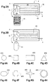
- the pressurizing means 5 is arranged outside the chamber 20 of the storage tank 2, can equally well envisage that the pressurizing means 5 is arranged inside the enclosure 20, as illustrated in FIGS. Figures 3A and 3B .
- the pressurizing means 5 consists of a pressure accumulator in the form of a movable piston 51 in the part 30 of the hydrogen circulation circuit within the chamber 2, while in figure 3B , the accumulator 5 is a flexible membrane accumulator 51 in the part 30.
- the tubes 400 of exchanger 40 within the chamber 2 may have different shapes such as circular section ( Figure 4A ), square ( Figure 4B ), rectangular ( figure 4C ), triangular ( figure 4D ), oblong ( figure 4E ), crossed ( figure 4F ), or even a four-pointed star section ( figure 4G ) or multi-branches ( Figure 4H ). These latter star-shaped shapes have the particular advantages of increasing the exchange surface and facilitating their integration into the heat exchanger.
Landscapes
- Engineering & Computer Science (AREA)
- Chemical Kinetics & Catalysis (AREA)
- Manufacturing & Machinery (AREA)
- Sustainable Development (AREA)
- Sustainable Energy (AREA)
- Chemical & Material Sciences (AREA)
- Life Sciences & Earth Sciences (AREA)
- Electrochemistry (AREA)
- General Chemical & Material Sciences (AREA)
- Mechanical Engineering (AREA)
- General Engineering & Computer Science (AREA)
- Filling Or Discharging Of Gas Storage Vessels (AREA)
- Fuel Cell (AREA)
Claims (15)
- Reversibles Speichersystem (1) für Wasserstoff, mit:- einem Speicherbehälter (2) für Wasserstoff, der eine Hülle (20) aufweist, die Metallhydride enthält, die in einen als erster Wärmetauscher bezeichneten Wärmetauscher (1) mit zwei Fluidkreisläufen integriert sind,- einem als erster Kreislauf bezeichneten Wasserstoffkreislauf (3), der mit dem Inneren der Hülle verbunden ist, um Wasserstoff H2, der durch die Metallhydride zu absorbieren oder zu desorbieren ist, zuzuführen bzw. zurückzugewinnen, wobei der Teil (30) des ersten Kreislaufes im Inneren der Hülle einen der Wärmetauscherkreisläufe bildet,
einem als zweiter Kreislauf bezeichneten Kreislauf für eine Wärmeträgerfluid (4), der mit dem Wärmetauscher verbunden ist, wobei der Teil (40) des zweiten Kreislaufs innerhalb des Wärmetauschers den anderen der Wärmetauscherkreisläufe bildet und die ersten und zweiten Kreisläufe gegeneinander abgedichtet sind,- einem Druckausgleichsmittel (5), das dazu dient, den Druck in dem zweiten Kreislauf auf einen Wert zu bringen, der im wesentlichen gleich dem Druck in dem ersten Kreislauf ist, mit einer Differenz, die typischerweise 1 bar oder 2 bis 3 bar beträgt. - System nach Anspruch 1, bei dem das Druckausgleichsmittel aus dem Rohr oder den Rohren (400) des Wärmetauschers (21) besteht, wobei der Querschnitt des Rohres oder der Rohre des Wärmetauschers so angepasst ist, dass sie sich ausreichend verformen können, um den Wert des Druckes in dem zweiten Kreislauf auf einen Wert in der Nähe des Druckes in dem ersten Kreislaufs zu bringen.
- System nach Anspruch 1, bei das Druckausgleichsmittel in einem Druckausgleicher besteht, das durch eine Hülle (50) gebildet wird, in deren Inneren ein bewegliches Element (51) befestigt ist, das eine erste Kammer (52) von einer zweiten Kammer (53) trennt und die Kammern gegeneinander abdichtet, wobei die erste Kammer (52) mit dem ersten Kreislauf (3) und die zweite Kammer (53) mit dem zweiten Kreislauf (4) verbunden ist.
- System nach Anspruch 3, bei dem das bewegliche Element eine flexible Membran (51) oder ein Kolben ist.
- System nach einem der vorstehenden Ansprüche, bei dem das Druckausgleichsmittel außerhalb des Speicherbehälters für H2 angeordnet ist.
- System nach einem der Ansprüche 1 bis 4, bei dem das Druckausgleichsmittel (5) innerhalb der Hülle (20) des Speicherbehälters für H2 angeordnet ist.
- System nach einem der vorstehenden Ansprüche, bei dem der zweite Kreislauf eine erste Pumpe (60) und einen weiteren Wärmetauscher (41) aufweist, der einen ersten sekundären Wärmetauscher bildet.
- Verfahren zum Betrieb eines Systems nach einem der vorstehenden Ansprüche, mit einem Schritt des permanenten Druckausgleiches, um den Druck in dem zweiten Kreislauf auf einen Wert in der Nähe des Druckes in dem ersten Kreislauf zu bringen.
- Verfahren nach Anspruch 8, bei dem der Schritt des Druckausgleiches automatisch ausgeführt wird.
- Verfahren nach Anspruch 9 oder 10, bei dem der Druck in dem zweiten Kreislauf grösser ist als derjenige in dem ersten Kreislauf.
- Verfahren nach Anspruch 10, bei dem der Druck in dem ersten Kreislauf wenigstens 350 bar beträgt und derjenige im zweiten Kreislauf um etwa 2 bis 3 bar größer ist.
- Verfahren nach einem der Ansprüche 8 bis 11, bei dem das in dem zweiten Kreislauf zirkulierende Wärmeträgerfluid eine Flüssigkeit ist, vorzugsweise auf wässriger Basis, insbesondere mit Glykol oder dergleichen.
- Verfahren nach einem der Ansprüche 8 bis 12, bei dem das sekundäre Fluid, das in dem sekundären Wärmetauscher (41) des zweiten Kreislaufs zirkuliert, eine Flüssigkeit ist, vorzugsweise Wasser, oder ein Gas, vorzugsweise Luft.
- Elektrische Versorgungsquelle mit einer Brennstoffzelle (7) und einem System (1) nach Anspruch 7, bei welcher der erste sekundäre Wärmetauscher (41) so mit der Brennstoffzelle verbunden ist, dass die im Betrieb von der Brennstoffzelle abgegebene Wärme die Desorption des Wasserstoffs in dem Behälter (2) ermöglicht.
- Stationäre Wasserstoffladestation mit einer Versorgungsquelle nach Anspruch 14 und einer zweiten Pumpe (44) und einem zweiten sekundären Wärmetauscher (45), wobei die zweite Pumpe und der zweite sekundäre Wärmetauscher beim Befüllen des Behälters (2) mit H2 mit dem zweiten Kreislauf verbunden sind.
Applications Claiming Priority (2)
| Application Number | Priority Date | Filing Date | Title |
|---|---|---|---|
| FR1450008A FR3016021B1 (fr) | 2014-01-02 | 2014-01-02 | Systeme de stockage reversible d'h2 avec reservoir contenant des hydrures metalliques, a equilibrage de pression |
| PCT/IB2014/067272 WO2015101905A1 (fr) | 2014-01-02 | 2014-12-23 | Systeme de stockage reversible d'h2 avec reservoir contenant des hydrures metalliques, a equilibrage de pression |
Publications (2)
| Publication Number | Publication Date |
|---|---|
| EP3090199A1 EP3090199A1 (de) | 2016-11-09 |
| EP3090199B1 true EP3090199B1 (de) | 2018-02-21 |
Family
ID=50877406
Family Applications (1)
| Application Number | Title | Priority Date | Filing Date |
|---|---|---|---|
| EP14835517.5A Active EP3090199B1 (de) | 2014-01-02 | 2014-12-23 | Umkehrbares h2-speichersystem mit einem tank mit metallhydriden und mit druckausgleich |
Country Status (7)
| Country | Link |
|---|---|
| US (1) | US20160327210A1 (de) |
| EP (1) | EP3090199B1 (de) |
| JP (1) | JP2017509838A (de) |
| CA (1) | CA2935694A1 (de) |
| DK (1) | DK3090199T3 (de) |
| FR (1) | FR3016021B1 (de) |
| WO (1) | WO2015101905A1 (de) |
Families Citing this family (9)
| Publication number | Priority date | Publication date | Assignee | Title |
|---|---|---|---|---|
| US10443890B2 (en) * | 2016-01-14 | 2019-10-15 | Benjamin Thomas KNOPP | Water heater with thermally isolating preheater and method of use |
| KR20170097386A (ko) | 2016-02-18 | 2017-08-28 | 현대자동차주식회사 | 고체수소저장 장치 |
| RU167720U1 (ru) * | 2016-04-28 | 2017-01-10 | Ксения Игоревна Денисова | Теплообменное устройство |
| FR3056230B1 (fr) | 2016-09-19 | 2020-02-28 | Commissariat A L'energie Atomique Et Aux Energies Alternatives | Systeme d'electrolyse reversible de l'eau a haute temperature comportant un reservoir d'hydrures couple a l'electrolyseur |
| FR3063331B1 (fr) * | 2017-02-24 | 2019-03-29 | Aaqius & Aaqius Sa | Systeme d'utilisation d'hydrogene |
| CN109708002B (zh) * | 2019-01-22 | 2021-08-17 | 武汉船用电力推进装置研究所(中国船舶重工集团公司第七一二研究所) | 一种温度补偿式合金储氢供氢系统 |
| GB2582607B (en) * | 2019-03-27 | 2023-12-06 | H2Go Power Ltd | Power supply |
| CN110783601B (zh) * | 2019-11-07 | 2020-10-27 | 安徽伯华氢能源科技有限公司 | 一种换热装置及加热系统 |
| WO2026093161A1 (en) * | 2024-11-01 | 2026-05-07 | Grz Technologies Sa | Hydrogen fueling system |
Family Cites Families (12)
| Publication number | Priority date | Publication date | Assignee | Title |
|---|---|---|---|---|
| JPS59217601A (ja) * | 1983-05-25 | 1984-12-07 | Toyobo Co Ltd | 水素吸蔵・放出装置の運転方法 |
| JPH04231701A (ja) * | 1990-12-27 | 1992-08-20 | Ishikawajima Harima Heavy Ind Co Ltd | アキュムレータ |
| JPH11173582A (ja) * | 1997-12-12 | 1999-06-29 | Sanyo Electric Co Ltd | 空気調和用の床暖マット |
| US6878353B2 (en) * | 2000-12-20 | 2005-04-12 | Texaco Ovonic Hydrogen Systems Llc | Hydrogen storage bed system including an integrated thermal management system |
| US7431756B2 (en) * | 2002-05-09 | 2008-10-07 | Ovonic Hydrogen Systems Llc | Modular metal hydride hydrogen storage system |
| JP2006177537A (ja) * | 2004-12-24 | 2006-07-06 | Toyota Industries Corp | 高圧タンクシステム |
| US7757726B2 (en) * | 2005-05-06 | 2010-07-20 | Kiyoshi Handa | System for enhancing the efficiency of high pressure storage tanks for compressed natural gas or hydrogen |
| US7938149B2 (en) * | 2006-04-13 | 2011-05-10 | Honda Motor Co, Ltd | Supplemental heat exchange for high pressure gas tank |
| JP2012516980A (ja) * | 2009-02-04 | 2012-07-26 | パーデュ リサーチ ファンデーション | 金属水素化物格納システムのための熱交換器 |
| JP2011080495A (ja) * | 2009-10-05 | 2011-04-21 | National Institute Of Advanced Industrial Science & Technology | 水素充填システムの水素用熱交換器 |
| FR2952696B1 (fr) * | 2009-11-13 | 2012-03-09 | Commissariat Energie Atomique | Reservoir de stockage d'hydrogene a hydrures metalliques |
| JP2013231457A (ja) * | 2012-04-27 | 2013-11-14 | Taiyo Nippon Sanso Corp | 水素ガス充填方法 |
-
2014
- 2014-01-02 FR FR1450008A patent/FR3016021B1/fr not_active Expired - Fee Related
- 2014-12-23 DK DK14835517.5T patent/DK3090199T3/en active
- 2014-12-23 US US15/109,755 patent/US20160327210A1/en not_active Abandoned
- 2014-12-23 JP JP2016544438A patent/JP2017509838A/ja active Pending
- 2014-12-23 WO PCT/IB2014/067272 patent/WO2015101905A1/fr not_active Ceased
- 2014-12-23 EP EP14835517.5A patent/EP3090199B1/de active Active
- 2014-12-23 CA CA2935694A patent/CA2935694A1/fr not_active Abandoned
Also Published As
| Publication number | Publication date |
|---|---|
| US20160327210A1 (en) | 2016-11-10 |
| FR3016021A1 (fr) | 2015-07-03 |
| WO2015101905A1 (fr) | 2015-07-09 |
| EP3090199A1 (de) | 2016-11-09 |
| DK3090199T3 (en) | 2018-05-28 |
| CA2935694A1 (fr) | 2015-07-09 |
| JP2017509838A (ja) | 2017-04-06 |
| FR3016021B1 (fr) | 2016-02-05 |
Similar Documents
| Publication | Publication Date | Title |
|---|---|---|
| EP3090199A1 (de) | Umkehrbares h2-speichersystem mit einem tank mit metallhydriden und mit druckausgleich | |
| EP2499088B1 (de) | Wasserstoffspeichertank mit metallhydriden | |
| EP2499418B1 (de) | Wasserstoffspeichertank mit metallhydriden | |
| EP2904304B1 (de) | Wasserstoffspeichertank mit durch vereinfachte herstellung hergestellten metallhydriden sowie lagerungsvorrichtung mit mindestens solch einem tank | |
| WO2011033192A1 (fr) | Réservoir de stockage et de déstockage d'hydrogène et/ou de chaleur | |
| EP3384200B1 (de) | Aus einem wärmeisolierenden material, das zylindrische gehäuse mit hydriden bildet, hergestellter wasserstoffspeicher und verfahren zur benutzung des wasserstoffspeichers | |
| EP3084288B1 (de) | Metallhydridwasserstoffspeichertank für die aufnahme von hydriden | |
| EP3234443B1 (de) | Metallhydridwasserstoffspeichertank mit mehreren gestapelten ebenen | |
| FR2984453A1 (fr) | Reservoir de stockage d'hydrogene sous la forme d'hydrures metalliques | |
| EP3084287A1 (de) | Wasserstoffspeichertank mit metallhydriden mit wärmespeichern | |
| EP3551927B1 (de) | Wasserstoffspeicher mit mehreren wasserdichten abdichtungen | |
| FR2953820A1 (fr) | Dispositif de stockage d'hydrogene a hydrures metalliques | |
| WO2021001198A1 (fr) | Systeme et procede de stockage et de recuperation de chaleur, comprenant un passage radial au sein de particules de stockage | |
| FR2999169A1 (fr) | Procede pyrotechnique de mise a disposition d'hydrogene faiblement pressurise et a une temperature inferieure a 200°c et dispositif associe | |
| EP3545225B1 (de) | Wasserstoffspeicher beinhaltend metallhydride mit einer verbesserten fixierung des pulvers | |
| FR2999167A1 (fr) | Procede pyrotechnique de mise a disposition d'hydrogene de tres grande purete et dispositif associe |
Legal Events
| Date | Code | Title | Description |
|---|---|---|---|
| PUAI | Public reference made under article 153(3) epc to a published international application that has entered the european phase |
Free format text: ORIGINAL CODE: 0009012 |
|
| 17P | Request for examination filed |
Effective date: 20160802 |
|
| AK | Designated contracting states |
Kind code of ref document: A1 Designated state(s): AL AT BE BG CH CY CZ DE DK EE ES FI FR GB GR HR HU IE IS IT LI LT LU LV MC MK MT NL NO PL PT RO RS SE SI SK SM TR |
|
| AX | Request for extension of the european patent |
Extension state: BA ME |
|
| DAX | Request for extension of the european patent (deleted) | ||
| GRAP | Despatch of communication of intention to grant a patent |
Free format text: ORIGINAL CODE: EPIDOSNIGR1 |
|
| STAA | Information on the status of an ep patent application or granted ep patent |
Free format text: STATUS: GRANT OF PATENT IS INTENDED |
|
| INTG | Intention to grant announced |
Effective date: 20170811 |
|
| GRAS | Grant fee paid |
Free format text: ORIGINAL CODE: EPIDOSNIGR3 |
|
| GRAA | (expected) grant |
Free format text: ORIGINAL CODE: 0009210 |
|
| STAA | Information on the status of an ep patent application or granted ep patent |
Free format text: STATUS: THE PATENT HAS BEEN GRANTED |
|
| AK | Designated contracting states |
Kind code of ref document: B1 Designated state(s): AL AT BE BG CH CY CZ DE DK EE ES FI FR GB GR HR HU IE IS IT LI LT LU LV MC MK MT NL NO PL PT RO RS SE SI SK SM TR |
|
| REG | Reference to a national code |
Ref country code: GB Ref legal event code: FG4D Free format text: NOT ENGLISH |
|
| REG | Reference to a national code |
Ref country code: CH Ref legal event code: EP |
|
| REG | Reference to a national code |
Ref country code: AT Ref legal event code: REF Ref document number: 972140 Country of ref document: AT Kind code of ref document: T Effective date: 20180315 |
|
| REG | Reference to a national code |
Ref country code: IE Ref legal event code: FG4D Free format text: LANGUAGE OF EP DOCUMENT: FRENCH |
|
| REG | Reference to a national code |
Ref country code: DE Ref legal event code: R096 Ref document number: 602014021449 Country of ref document: DE |
|
| REG | Reference to a national code |
Ref country code: DK Ref legal event code: T3 Effective date: 20180525 |
|
| REG | Reference to a national code |
Ref country code: NL Ref legal event code: MP Effective date: 20180221 |
|
| REG | Reference to a national code |
Ref country code: LT Ref legal event code: MG4D |
|
| REG | Reference to a national code |
Ref country code: AT Ref legal event code: MK05 Ref document number: 972140 Country of ref document: AT Kind code of ref document: T Effective date: 20180221 |
|
| PG25 | Lapsed in a contracting state [announced via postgrant information from national office to epo] |
Ref country code: FI Free format text: LAPSE BECAUSE OF FAILURE TO SUBMIT A TRANSLATION OF THE DESCRIPTION OR TO PAY THE FEE WITHIN THE PRESCRIBED TIME-LIMIT Effective date: 20180221 Ref country code: NO Free format text: LAPSE BECAUSE OF FAILURE TO SUBMIT A TRANSLATION OF THE DESCRIPTION OR TO PAY THE FEE WITHIN THE PRESCRIBED TIME-LIMIT Effective date: 20180521 Ref country code: NL Free format text: LAPSE BECAUSE OF FAILURE TO SUBMIT A TRANSLATION OF THE DESCRIPTION OR TO PAY THE FEE WITHIN THE PRESCRIBED TIME-LIMIT Effective date: 20180221 Ref country code: HR Free format text: LAPSE BECAUSE OF FAILURE TO SUBMIT A TRANSLATION OF THE DESCRIPTION OR TO PAY THE FEE WITHIN THE PRESCRIBED TIME-LIMIT Effective date: 20180221 Ref country code: LT Free format text: LAPSE BECAUSE OF FAILURE TO SUBMIT A TRANSLATION OF THE DESCRIPTION OR TO PAY THE FEE WITHIN THE PRESCRIBED TIME-LIMIT Effective date: 20180221 Ref country code: ES Free format text: LAPSE BECAUSE OF FAILURE TO SUBMIT A TRANSLATION OF THE DESCRIPTION OR TO PAY THE FEE WITHIN THE PRESCRIBED TIME-LIMIT Effective date: 20180221 Ref country code: CY Free format text: LAPSE BECAUSE OF FAILURE TO SUBMIT A TRANSLATION OF THE DESCRIPTION OR TO PAY THE FEE WITHIN THE PRESCRIBED TIME-LIMIT Effective date: 20180221 |
|
| PG25 | Lapsed in a contracting state [announced via postgrant information from national office to epo] |
Ref country code: BG Free format text: LAPSE BECAUSE OF FAILURE TO SUBMIT A TRANSLATION OF THE DESCRIPTION OR TO PAY THE FEE WITHIN THE PRESCRIBED TIME-LIMIT Effective date: 20180521 Ref country code: GR Free format text: LAPSE BECAUSE OF FAILURE TO SUBMIT A TRANSLATION OF THE DESCRIPTION OR TO PAY THE FEE WITHIN THE PRESCRIBED TIME-LIMIT Effective date: 20180522 Ref country code: SE Free format text: LAPSE BECAUSE OF FAILURE TO SUBMIT A TRANSLATION OF THE DESCRIPTION OR TO PAY THE FEE WITHIN THE PRESCRIBED TIME-LIMIT Effective date: 20180221 Ref country code: LV Free format text: LAPSE BECAUSE OF FAILURE TO SUBMIT A TRANSLATION OF THE DESCRIPTION OR TO PAY THE FEE WITHIN THE PRESCRIBED TIME-LIMIT Effective date: 20180221 Ref country code: AT Free format text: LAPSE BECAUSE OF FAILURE TO SUBMIT A TRANSLATION OF THE DESCRIPTION OR TO PAY THE FEE WITHIN THE PRESCRIBED TIME-LIMIT Effective date: 20180221 Ref country code: RS Free format text: LAPSE BECAUSE OF FAILURE TO SUBMIT A TRANSLATION OF THE DESCRIPTION OR TO PAY THE FEE WITHIN THE PRESCRIBED TIME-LIMIT Effective date: 20180221 |
|
| PG25 | Lapsed in a contracting state [announced via postgrant information from national office to epo] |
Ref country code: MT Free format text: LAPSE BECAUSE OF FAILURE TO SUBMIT A TRANSLATION OF THE DESCRIPTION OR TO PAY THE FEE WITHIN THE PRESCRIBED TIME-LIMIT Effective date: 20180221 |
|
| PG25 | Lapsed in a contracting state [announced via postgrant information from national office to epo] |
Ref country code: EE Free format text: LAPSE BECAUSE OF FAILURE TO SUBMIT A TRANSLATION OF THE DESCRIPTION OR TO PAY THE FEE WITHIN THE PRESCRIBED TIME-LIMIT Effective date: 20180221 Ref country code: AL Free format text: LAPSE BECAUSE OF FAILURE TO SUBMIT A TRANSLATION OF THE DESCRIPTION OR TO PAY THE FEE WITHIN THE PRESCRIBED TIME-LIMIT Effective date: 20180221 Ref country code: PL Free format text: LAPSE BECAUSE OF FAILURE TO SUBMIT A TRANSLATION OF THE DESCRIPTION OR TO PAY THE FEE WITHIN THE PRESCRIBED TIME-LIMIT Effective date: 20180221 |
|
| REG | Reference to a national code |
Ref country code: DE Ref legal event code: R097 Ref document number: 602014021449 Country of ref document: DE |
|
| PG25 | Lapsed in a contracting state [announced via postgrant information from national office to epo] |
Ref country code: CZ Free format text: LAPSE BECAUSE OF FAILURE TO SUBMIT A TRANSLATION OF THE DESCRIPTION OR TO PAY THE FEE WITHIN THE PRESCRIBED TIME-LIMIT Effective date: 20180221 Ref country code: SK Free format text: LAPSE BECAUSE OF FAILURE TO SUBMIT A TRANSLATION OF THE DESCRIPTION OR TO PAY THE FEE WITHIN THE PRESCRIBED TIME-LIMIT Effective date: 20180221 Ref country code: SM Free format text: LAPSE BECAUSE OF FAILURE TO SUBMIT A TRANSLATION OF THE DESCRIPTION OR TO PAY THE FEE WITHIN THE PRESCRIBED TIME-LIMIT Effective date: 20180221 |
|
| PLBE | No opposition filed within time limit |
Free format text: ORIGINAL CODE: 0009261 |
|
| STAA | Information on the status of an ep patent application or granted ep patent |
Free format text: STATUS: NO OPPOSITION FILED WITHIN TIME LIMIT |
|
| 26N | No opposition filed |
Effective date: 20181122 |
|
| PG25 | Lapsed in a contracting state [announced via postgrant information from national office to epo] |
Ref country code: SI Free format text: LAPSE BECAUSE OF FAILURE TO SUBMIT A TRANSLATION OF THE DESCRIPTION OR TO PAY THE FEE WITHIN THE PRESCRIBED TIME-LIMIT Effective date: 20180221 |
|
| PG25 | Lapsed in a contracting state [announced via postgrant information from national office to epo] |
Ref country code: MC Free format text: LAPSE BECAUSE OF FAILURE TO SUBMIT A TRANSLATION OF THE DESCRIPTION OR TO PAY THE FEE WITHIN THE PRESCRIBED TIME-LIMIT Effective date: 20180221 Ref country code: LU Free format text: LAPSE BECAUSE OF NON-PAYMENT OF DUE FEES Effective date: 20181223 |
|
| REG | Reference to a national code |
Ref country code: IE Ref legal event code: MM4A |
|
| REG | Reference to a national code |
Ref country code: BE Ref legal event code: MM Effective date: 20181231 |
|
| PG25 | Lapsed in a contracting state [announced via postgrant information from national office to epo] |
Ref country code: IE Free format text: LAPSE BECAUSE OF NON-PAYMENT OF DUE FEES Effective date: 20181223 |
|
| PG25 | Lapsed in a contracting state [announced via postgrant information from national office to epo] |
Ref country code: BE Free format text: LAPSE BECAUSE OF NON-PAYMENT OF DUE FEES Effective date: 20181231 |
|
| PG25 | Lapsed in a contracting state [announced via postgrant information from national office to epo] |
Ref country code: TR Free format text: LAPSE BECAUSE OF FAILURE TO SUBMIT A TRANSLATION OF THE DESCRIPTION OR TO PAY THE FEE WITHIN THE PRESCRIBED TIME-LIMIT Effective date: 20180221 |
|
| PG25 | Lapsed in a contracting state [announced via postgrant information from national office to epo] |
Ref country code: PT Free format text: LAPSE BECAUSE OF FAILURE TO SUBMIT A TRANSLATION OF THE DESCRIPTION OR TO PAY THE FEE WITHIN THE PRESCRIBED TIME-LIMIT Effective date: 20180221 |
|
| PG25 | Lapsed in a contracting state [announced via postgrant information from national office to epo] |
Ref country code: RO Free format text: LAPSE BECAUSE OF FAILURE TO SUBMIT A TRANSLATION OF THE DESCRIPTION OR TO PAY THE FEE WITHIN THE PRESCRIBED TIME-LIMIT Effective date: 20180221 Ref country code: HU Free format text: LAPSE BECAUSE OF FAILURE TO SUBMIT A TRANSLATION OF THE DESCRIPTION OR TO PAY THE FEE WITHIN THE PRESCRIBED TIME-LIMIT; INVALID AB INITIO Effective date: 20141223 Ref country code: MK Free format text: LAPSE BECAUSE OF NON-PAYMENT OF DUE FEES Effective date: 20180221 |
|
| PG25 | Lapsed in a contracting state [announced via postgrant information from national office to epo] |
Ref country code: IS Free format text: LAPSE BECAUSE OF FAILURE TO SUBMIT A TRANSLATION OF THE DESCRIPTION OR TO PAY THE FEE WITHIN THE PRESCRIBED TIME-LIMIT Effective date: 20180621 |
|
| PGFP | Annual fee paid to national office [announced via postgrant information from national office to epo] |
Ref country code: DK Payment date: 20241217 Year of fee payment: 11 |
|
| PGFP | Annual fee paid to national office [announced via postgrant information from national office to epo] |
Ref country code: GB Payment date: 20241227 Year of fee payment: 11 |
|
| PGFP | Annual fee paid to national office [announced via postgrant information from national office to epo] |
Ref country code: FR Payment date: 20241227 Year of fee payment: 11 |
|
| PGFP | Annual fee paid to national office [announced via postgrant information from national office to epo] |
Ref country code: IT Payment date: 20241216 Year of fee payment: 11 |
|
| PGFP | Annual fee paid to national office [announced via postgrant information from national office to epo] |
Ref country code: DE Payment date: 20241219 Year of fee payment: 11 |
|
| PGFP | Annual fee paid to national office [announced via postgrant information from national office to epo] |
Ref country code: CH Payment date: 20250101 Year of fee payment: 11 |
|
| REG | Reference to a national code |
Ref country code: DK Ref legal event code: EBP Effective date: 20251231 |
|
| REG | Reference to a national code |
Ref country code: CH Ref legal event code: H13 Free format text: ST27 STATUS EVENT CODE: U-0-0-H10-H13 (AS PROVIDED BY THE NATIONAL OFFICE) Effective date: 20260723 |