EP3090217B1 - Appareil à cycle de refroidissement pour réfrigérateur - Google Patents
Appareil à cycle de refroidissement pour réfrigérateur Download PDFInfo
- Publication number
- EP3090217B1 EP3090217B1 EP16724577.8A EP16724577A EP3090217B1 EP 3090217 B1 EP3090217 B1 EP 3090217B1 EP 16724577 A EP16724577 A EP 16724577A EP 3090217 B1 EP3090217 B1 EP 3090217B1
- Authority
- EP
- European Patent Office
- Prior art keywords
- refrigerant
- gas
- compressor
- evaporator
- expansion device
- Prior art date
- Legal status (The legal status is an assumption and is not a legal conclusion. Google has not performed a legal analysis and makes no representation as to the accuracy of the status listed.)
- Active
Links
Images




Classifications
-
- F—MECHANICAL ENGINEERING; LIGHTING; HEATING; WEAPONS; BLASTING
- F25—REFRIGERATION OR COOLING; COMBINED HEATING AND REFRIGERATION SYSTEMS; HEAT PUMP SYSTEMS; MANUFACTURE OR STORAGE OF ICE; LIQUEFACTION SOLIDIFICATION OF GASES
- F25D—REFRIGERATORS; COLD ROOMS; ICE-BOXES; COOLING OR FREEZING APPARATUS NOT OTHERWISE PROVIDED FOR
- F25D11/00—Self-contained movable devices, e.g. domestic refrigerators
- F25D11/02—Self-contained movable devices, e.g. domestic refrigerators with cooling compartments at different temperatures
- F25D11/022—Self-contained movable devices, e.g. domestic refrigerators with cooling compartments at different temperatures with two or more evaporators
-
- F—MECHANICAL ENGINEERING; LIGHTING; HEATING; WEAPONS; BLASTING
- F25—REFRIGERATION OR COOLING; COMBINED HEATING AND REFRIGERATION SYSTEMS; HEAT PUMP SYSTEMS; MANUFACTURE OR STORAGE OF ICE; LIQUEFACTION SOLIDIFICATION OF GASES
- F25B—REFRIGERATION MACHINES, PLANTS OR SYSTEMS; COMBINED HEATING AND REFRIGERATION SYSTEMS; HEAT PUMP SYSTEMS
- F25B5/00—Compression machines, plants or systems, with several evaporator circuits, e.g. for varying refrigerating capacity
- F25B5/02—Compression machines, plants or systems, with several evaporator circuits, e.g. for varying refrigerating capacity arranged in parallel
-
- F—MECHANICAL ENGINEERING; LIGHTING; HEATING; WEAPONS; BLASTING
- F25—REFRIGERATION OR COOLING; COMBINED HEATING AND REFRIGERATION SYSTEMS; HEAT PUMP SYSTEMS; MANUFACTURE OR STORAGE OF ICE; LIQUEFACTION SOLIDIFICATION OF GASES
- F25B—REFRIGERATION MACHINES, PLANTS OR SYSTEMS; COMBINED HEATING AND REFRIGERATION SYSTEMS; HEAT PUMP SYSTEMS
- F25B1/00—Compression machines, plants or systems with non-reversible cycle
- F25B1/10—Compression machines, plants or systems with non-reversible cycle with multi-stage compression
-
- F—MECHANICAL ENGINEERING; LIGHTING; HEATING; WEAPONS; BLASTING
- F25—REFRIGERATION OR COOLING; COMBINED HEATING AND REFRIGERATION SYSTEMS; HEAT PUMP SYSTEMS; MANUFACTURE OR STORAGE OF ICE; LIQUEFACTION SOLIDIFICATION OF GASES
- F25B—REFRIGERATION MACHINES, PLANTS OR SYSTEMS; COMBINED HEATING AND REFRIGERATION SYSTEMS; HEAT PUMP SYSTEMS
- F25B40/00—Subcoolers, desuperheaters or superheaters
-
- F—MECHANICAL ENGINEERING; LIGHTING; HEATING; WEAPONS; BLASTING
- F25—REFRIGERATION OR COOLING; COMBINED HEATING AND REFRIGERATION SYSTEMS; HEAT PUMP SYSTEMS; MANUFACTURE OR STORAGE OF ICE; LIQUEFACTION SOLIDIFICATION OF GASES
- F25B—REFRIGERATION MACHINES, PLANTS OR SYSTEMS; COMBINED HEATING AND REFRIGERATION SYSTEMS; HEAT PUMP SYSTEMS
- F25B40/00—Subcoolers, desuperheaters or superheaters
- F25B40/04—Desuperheaters
-
- F—MECHANICAL ENGINEERING; LIGHTING; HEATING; WEAPONS; BLASTING
- F25—REFRIGERATION OR COOLING; COMBINED HEATING AND REFRIGERATION SYSTEMS; HEAT PUMP SYSTEMS; MANUFACTURE OR STORAGE OF ICE; LIQUEFACTION SOLIDIFICATION OF GASES
- F25B—REFRIGERATION MACHINES, PLANTS OR SYSTEMS; COMBINED HEATING AND REFRIGERATION SYSTEMS; HEAT PUMP SYSTEMS
- F25B41/00—Fluid-circulation arrangements
- F25B41/30—Expansion means; Dispositions thereof
- F25B41/39—Dispositions with two or more expansion means arranged in series, i.e. multi-stage expansion, on a refrigerant line leading to the same evaporator
-
- F—MECHANICAL ENGINEERING; LIGHTING; HEATING; WEAPONS; BLASTING
- F25—REFRIGERATION OR COOLING; COMBINED HEATING AND REFRIGERATION SYSTEMS; HEAT PUMP SYSTEMS; MANUFACTURE OR STORAGE OF ICE; LIQUEFACTION SOLIDIFICATION OF GASES
- F25B—REFRIGERATION MACHINES, PLANTS OR SYSTEMS; COMBINED HEATING AND REFRIGERATION SYSTEMS; HEAT PUMP SYSTEMS
- F25B2341/00—Details of ejectors not being used as compression device; Details of flow restrictors or expansion valves
- F25B2341/06—Details of flow restrictors or expansion valves
- F25B2341/062—Capillary expansion valves
-
- F—MECHANICAL ENGINEERING; LIGHTING; HEATING; WEAPONS; BLASTING
- F25—REFRIGERATION OR COOLING; COMBINED HEATING AND REFRIGERATION SYSTEMS; HEAT PUMP SYSTEMS; MANUFACTURE OR STORAGE OF ICE; LIQUEFACTION SOLIDIFICATION OF GASES
- F25B—REFRIGERATION MACHINES, PLANTS OR SYSTEMS; COMBINED HEATING AND REFRIGERATION SYSTEMS; HEAT PUMP SYSTEMS
- F25B2400/00—Component parts or details not otherwise provided for in this subclass
- F25B2400/05—Compression system with heat exchange between particular parts of the system
- F25B2400/054—Compression system with heat exchange between particular parts of the system between the suction tube of the compressor and another part of the cycle
-
- F—MECHANICAL ENGINEERING; LIGHTING; HEATING; WEAPONS; BLASTING
- F25—REFRIGERATION OR COOLING; COMBINED HEATING AND REFRIGERATION SYSTEMS; HEAT PUMP SYSTEMS; MANUFACTURE OR STORAGE OF ICE; LIQUEFACTION SOLIDIFICATION OF GASES
- F25B—REFRIGERATION MACHINES, PLANTS OR SYSTEMS; COMBINED HEATING AND REFRIGERATION SYSTEMS; HEAT PUMP SYSTEMS
- F25B2400/00—Component parts or details not otherwise provided for in this subclass
- F25B2400/07—Details of compressors or related parts
- F25B2400/075—Details of compressors or related parts with parallel compressors
-
- F—MECHANICAL ENGINEERING; LIGHTING; HEATING; WEAPONS; BLASTING
- F25—REFRIGERATION OR COOLING; COMBINED HEATING AND REFRIGERATION SYSTEMS; HEAT PUMP SYSTEMS; MANUFACTURE OR STORAGE OF ICE; LIQUEFACTION SOLIDIFICATION OF GASES
- F25B—REFRIGERATION MACHINES, PLANTS OR SYSTEMS; COMBINED HEATING AND REFRIGERATION SYSTEMS; HEAT PUMP SYSTEMS
- F25B2400/00—Component parts or details not otherwise provided for in this subclass
- F25B2400/13—Economisers
-
- F—MECHANICAL ENGINEERING; LIGHTING; HEATING; WEAPONS; BLASTING
- F25—REFRIGERATION OR COOLING; COMBINED HEATING AND REFRIGERATION SYSTEMS; HEAT PUMP SYSTEMS; MANUFACTURE OR STORAGE OF ICE; LIQUEFACTION SOLIDIFICATION OF GASES
- F25B—REFRIGERATION MACHINES, PLANTS OR SYSTEMS; COMBINED HEATING AND REFRIGERATION SYSTEMS; HEAT PUMP SYSTEMS
- F25B2400/00—Component parts or details not otherwise provided for in this subclass
- F25B2400/23—Separators
-
- F—MECHANICAL ENGINEERING; LIGHTING; HEATING; WEAPONS; BLASTING
- F25—REFRIGERATION OR COOLING; COMBINED HEATING AND REFRIGERATION SYSTEMS; HEAT PUMP SYSTEMS; MANUFACTURE OR STORAGE OF ICE; LIQUEFACTION SOLIDIFICATION OF GASES
- F25B—REFRIGERATION MACHINES, PLANTS OR SYSTEMS; COMBINED HEATING AND REFRIGERATION SYSTEMS; HEAT PUMP SYSTEMS
- F25B2600/00—Control issues
- F25B2600/25—Control of valves
- F25B2600/2509—Economiser valves
-
- F—MECHANICAL ENGINEERING; LIGHTING; HEATING; WEAPONS; BLASTING
- F25—REFRIGERATION OR COOLING; COMBINED HEATING AND REFRIGERATION SYSTEMS; HEAT PUMP SYSTEMS; MANUFACTURE OR STORAGE OF ICE; LIQUEFACTION SOLIDIFICATION OF GASES
- F25B—REFRIGERATION MACHINES, PLANTS OR SYSTEMS; COMBINED HEATING AND REFRIGERATION SYSTEMS; HEAT PUMP SYSTEMS
- F25B41/00—Fluid-circulation arrangements
- F25B41/30—Expansion means; Dispositions thereof
- F25B41/385—Dispositions with two or more expansion means arranged in parallel on a refrigerant line leading to the same evaporator
Definitions
- the present invention relates to a cooling cycle apparatus for a refrigerator, and more particularly to a cooling cycle apparatus for a refrigerator in which a gas-liquid separator is appropriately connected to the cooling cycle of the refrigerator so as to enhance the cooling efficiency thereof.
- cooling cycle refers to a cycle of a thermodynamic process of absorbing heat from a cold mass and transferring the heat to a thermal mass.
- the simplest apparatus using such a cooling cycle may include a compressor, a condenser, an expansion device and an evaporator.
- the compressor serves to compress a refrigerant and discharge the refrigerant in the form of high-temperature and high-pressure gas
- the condenser serves to condense the high-temperature and high-pressure refrigerant discharged from the compressor into a liquid-phase refrigerant having an intermediate or lower temperature and a high pressure
- the expansion device serves to expand the refrigerant having an intermediate or lower temperature and a high pressure, into a low-temperature and low-pressure refrigerant, and the expanded refrigerant is evaporated in the evaporator. At this time, the temperature and pressure of the refrigerant decreases further. Upon evaporation of the refrigerant, the refrigerant absorbs ambient heat, thus cooling the ambient air.
- a capillary tube or an expansion valve may be used as the expansion device.
- the refrigerant which has been circulated through one cycle, is transferred to the compressor again, and repeatedly undergoes the cyclical process.
- the evaporator absorbs ambient heat, whereby cooled air or cold air is generated.
- the refrigerator transfers the cold air to a cooling compartment by means of a blower, thereby cooling the inside of the cooling compartment.
- An increase in the amount of heat of the evaporator in the cooling cycle means increased cooling performance relative to the amount of work done by the compressor (coefficient of performance; COP).
- the evaporator is constructed such that a liquid-phase refrigerant absorbs heat from the ambient air while being evaporated, that is, being vaporized.
- the increase in the dryness of the evaporator means that an increasing proportion of the refrigerant introduced into the evaporator is gas-phase refrigerant.
- the gas-phase refrigerant is not evaporated in the evaporator, there is a problem in that the gas-phase refrigerant is not able to behave as a heat source for the evaporator, thereby decreasing the COP.
- the conventional cooling cycle is provided with an accumulator, which is adapted to separate the liquid-phase refrigerant, which has still not evaporated, from the refrigerant that has passed through the evaporator, and to transfer only this gas-phase refrigerant to the compressor, there is a problem whereby the separated liquid-phase refrigerant accumulates in the accumulator and thus cannot be reused.
- US 2002/069654 A1 discloses a cooling cycle apparatus for a refrigerator according to the preamble of claim 1.
- the disclosed cooling cycle apparatus has a two-stage compressor and means for switching refrigerant flow between a primary channel and a bypassing channel at downstream of a condenser that is connected with an outlet of the two-stage compressor.
- the present invention has been made in view of the above problems, and it is an object of the present invention to provide a cooling cycle apparatus for a refrigerator in which a gas-liquid separator is connected to the outlet of an expansion device so as to lower the dryness of an evaporator and increase the amount of heat of the evaporator, thereby enhancing the COP of the cooling cycle and lowering power consumption.
- the first compressor may compress the refrigerant at a higher pressure than the second compressor.
- the third expansion device may be shorter than the second expansion device.
- Cold air generated in the first evaporator may be supplied to a refrigerating compartment, and cold air generated in the second evaporator may be supplied to a freezing compartment.
- the cooling cycle apparatus may further include a heat exchanging unit, which is provided downstream of the condenser so as to exchange heat between the gas-phase refrigerant that has passed through the gas-liquid separator and the refrigerant that was condensed in the condenser.
- a heat exchanging unit which is provided downstream of the condenser so as to exchange heat between the gas-phase refrigerant that has passed through the gas-liquid separator and the refrigerant that was condensed in the condenser.
- the cooling cycle apparatus may further include a control valve, which is provided on a flow channel, which extends from the gas-liquid separator to a downstream flow channel of the first evaporator through the heat exchanging unit and through which the gas-phase refrigerant separated in the gas-liquid separator flows, so as to control an opening degree of the flow channel.
- a control valve which is provided on a flow channel, which extends from the gas-liquid separator to a downstream flow channel of the first evaporator through the heat exchanging unit and through which the gas-phase refrigerant separated in the gas-liquid separator flows, so as to control an opening degree of the flow channel.
- the cooling cycle apparatus may further include a heat exchanging unit, which is provided downstream of the first compressor so as to enable heat exchange between the gas-phase refrigerant that has passed through the gas-liquid separator and the refrigerant that has been compressed in the first compressor.
- a heat exchanging unit which is provided downstream of the first compressor so as to enable heat exchange between the gas-phase refrigerant that has passed through the gas-liquid separator and the refrigerant that has been compressed in the first compressor.
- the heat exchanging unit may lower the pressure of the refrigerant compressed in the first compressor.
- a cooling cycle apparatus for a refrigerator including a first compressor for compressing a refrigerant, a condenser for condensing the refrigerant compressed in the first compressor, a first expansion device for lowering the temperature and pressure of a portion of the refrigerant condensed in the condenser, a first evaporator for evaporating the refrigerant that has passed through the first expansion device, a second expansion device for lowering the temperature and pressure of a remaining portion of the refrigerant condensed in the condenser, a gas-liquid separator for separating a liquid-phase refrigerant from gas-phase refrigerant in the refrigerant that has passed through the first evaporator, a third expansion device for lowering the temperature and pressure of the liquid-phase refrigerant separated in the gas-liquid separator, a second evaporator for evaporating the refrigerant that has passed through the second expansion device and the refrigerant
- the first compressor may compress the refrigerant at a higher pressure than the second compressor.
- the third expansion device may be shorter than the second expansion device.
- Cold air generated in the first evaporator may be supplied to a refrigerating compartment, and cold air generated in the second evaporator may be supplied to a freezing compartment.
- a cooling cycle apparatus for a refrigerator including a compressor for compressing a refrigerant, a condenser for condensing the refrigerant compressed in the compressor, an expansion device for lowering the temperature and pressure of the refrigerant condensed in the condenser, a gas-liquid separator for separating liquid-phase refrigerant from gas-phase refrigerant in the refrigerant that has passed through the expansion device, a second evaporator for evaporating the liquid-phase refrigerant that was separated in the gas-liquid separator, and a heat exchanging unit for enabling heat exchange between the gas-phase refrigerant that was separated in the gas-liquid separator and the liquid-phase refrigerant condensed in the condenser and transferring the gas-phase refrigerant to the compressor.
- the cooling cycle apparatus may further include a control valve, which is provided on a flow channel, which extends from the gas-liquid separator to a flow channel located upstream of the compressor through the heat exchanging unit and through which the gas-phase refrigerant, which was separated in the gas-liquid separator, flows, so as to control an opening degree of the flow channel.
- a control valve which is provided on a flow channel, which extends from the gas-liquid separator to a flow channel located upstream of the compressor through the heat exchanging unit and through which the gas-phase refrigerant, which was separated in the gas-liquid separator, flows, so as to control an opening degree of the flow channel.
- a cooling cycle apparatus for a refrigerator including a compressor for compressing a refrigerant, a condenser for condensing the refrigerant compressed in the compressor, an expansion device for lowering the temperature and pressure of the refrigerant condensed in the condenser, a gas-liquid separator for separating liquid-phase refrigerant from gas-phase refrigerant in the refrigerant that has passed through the expansion device, a second evaporator for evaporating the liquid-phase refrigerant separated in the gas-liquid separator, and a heat exchanging unit for enabling heat exchange between the gas-phase refrigerant separated in the gas-liquid separator and the refrigerant compressed in the compressor and transferring the gas-phase refrigerant to the compressor.
- the cooling cycle apparatus may further include a control valve, which is provided on a flow channel, which extends from the gas-liquid separator to a flow channel located upstream of the compressor through the heat exchanging unit and through which the gas-phase refrigerant, which was separated in the gas-liquid separator, flows, so as to control an opening degree of the flow channel.
- a control valve which is provided on a flow channel, which extends from the gas-liquid separator to a flow channel located upstream of the compressor through the heat exchanging unit and through which the gas-phase refrigerant, which was separated in the gas-liquid separator, flows, so as to control an opening degree of the flow channel.
- cooling cycle apparatus for a refrigerator as described above, there is an effect of lowering the dryness of the evaporator and increasing the amount of heat of the evaporator by separating a gas-phase refrigerant from the refrigerant that has passed through the expansion device and transferring the refrigerant to the evaporator.
- the liquid-phase refrigerant is evaporated in the evaporator and is introduced into the compressor, and the gas-phase refrigerant separated in the gas-liquid separator is introduced into the compressor again and is compressed together with the gas-phase refrigerant, thereby enabling all of the refrigerant to be circulated and used in the cooling cycle apparatus.
- the gas-phase refrigerant separated in the gas-liquid separator exchanges heat with the refrigerant condensed in the condenser so as to increase the amount of condensation heat, or exchanges heat with the refrigerant compressed in the compressor so as to lower the discharge pressure of the compressor, thereby enhancing the efficiency of the refrigerating system.
- FIG. 1 is a view showing a cooling cycle apparatus not being part of the invention.
- the cooling cycle apparatus includes compressors, a condenser, expansion devices and evaporators.
- Refrigerant is doubly compressed by two compressors 110 and 210.
- the evaporators include a first evaporator 160 and a second evaporator 260 such that cold air generated in the respective evaporator is respectively blown to a refrigerating compartment and a freezing compartment.
- the high-temperature and high-pressure gas-phase refrigerant compressed in the first compressor 110 is condensed while passing through the condenser 120.
- the refrigerant condensed in the condenser 120 is diverged into two refrigerant portions, one portion of which is transferred to the first expansion device 140 and the other portion of which is transferred to the second expansion device 150.
- the refrigerant that has passed through the first expansion device 140 is transferred to the first evaporator 160.
- the refrigerant is evaporated at the first evaporator 160, and is introduced back into the first compressor 110 to thus be circulated.
- the refrigerant that has passed through the second expansion device 150 is introduced into a gas-liquid separator 170 where the refrigerant is divided into a liquid-phase refrigerant and gas-phase refrigerant.
- the liquid-phase refrigerant separated in the gas-liquid separator 170 is expanded again while passing through the third expansion device 240.
- the low-temperature and low-pressure refrigerant expanded at the third expansion device 240 is introduced into the second evaporator 260, in which the refrigerant exchanges heat with ambient air while being evaporated.
- the refrigerant that has passed through the second evaporator 260 is introduced into the second compressor 210, and is firstly compressed therein.
- the refrigerant is then introduced into the first compressor 110, and is secondly compressed therein.
- the refrigerant that has passed through the first evaporator 160 and the gas-phase refrigerant separated in the gas-liquid separator 170 are mixed with the refrigerant that has been compressed in the second compressor 210, and the mixed refrigerant is introduced into the first compressor 110.
- the refrigerant that has passed through the first evaporator 160 and the gas-phase refrigerant separated in the gas-liquid separator 170 are mixed with each other at a connecting portion, which is denoted by reference numeral "180", by the connection of the associated refrigerant pipes.
- the first compressor 110 preferably compresses the refrigerant at a higher pressure than the second compressor 210.
- the first compressor 110 and the second compressor 210 are connected to each other in series.
- the second compressor 210 serves as the lower-pressure compressor, and the first compressor 110 serves as the higher-pressure compressor.
- the refrigerant may pass through only the first compressor 110 or both the first compressor 110 and the second compressor 210. Naturally, the latter case will achieve higher freezing performance.
- the third expansion device 240 is preferably shorter than the second expansion device 150.
- the expansion devices may be constituted by capillary tubes or expansion valves. The longer the expansion device, the more the refrigerant is expanded and the greater the decrease in the pressure of the refrigerant.
- the refrigerant is further expanded. At this time, some of the expanded refrigerant may evaporate, thereby generating gas-phase refrigerant. Accordingly, the gas-phase refrigerant is separated in the gas-liquid separator 170, and only the liquid-phase refrigerant is transferred to the third expansion device 240.
- the refrigerant that has passed through the third expansion device 240 may also contain a small amount of gas-phase refrigerant, since the third expansion device 240 is shorter than the second expansion device 150, the proportion of gas-phase refrigerant in the refrigerant introduced into the second evaporator may be much lower than otherwise.
- the first expansion device 140 may be longer or shorter than the second expansion device 150, or may be approximately the same length as the second expansion device 150.
- the gas-liquid separator 170 may adopt any of a type using surface tension and a difference in density and a type using centrifugal force and a difference in density.
- the gas-liquid separator that uses surface tension and a difference in density separates liquid-phase refrigerant from gas-phase refrigerant by employing the tendency for liquid-phase refrigerant to adhere to the surfaces of grooves formed in the inner surface of the gas-liquid separator, and causes the liquid-phase refrigerant to move downward and the gas-phase refrigerant to move upward due to the difference in density.
- the gas-liquid separator that uses centrifugal force and a difference in density separates liquid-phase refrigerant from gas-phase refrigerant by rotating the cylindrical gas-liquid separator while refrigerant is being introduced into the gas-liquid separator so as to cause liquid-phase refrigerant to be separated from gas-phase refrigerant and to move downward and to cause gas-phase refrigerant to move upward.
- the cold air generated in the first evaporator 160 be supplied to the refrigerating compartment and that the cold air generated in the second evaporator 260 be supplied to the freezing compartment.
- the refrigerant that has passed through the first evaporator 160 is compressed only by the first compressor 110, and is expanded only by the first expansion device 140.
- the refrigerant that has passed through the second evaporator 260 is dually compressed by the second compressor 210 and the first compressor 110, and is dually expanded while passing through the second expansion device 150 and the third expansion device 240. Consequently, the cold air generated in the second evaporator 260 will have a lower temperature than the cold air generated in the first evaporator 160.
- the cold air generated in the first evaporator 160 may be supplied to the refrigerating compartment which is typically maintained at a temperature above zero, and the cold air generated in the second evaporator 260 may be supplied to the freezing compartment which is maintained at a temperature below zero.
- the cold air generated in the respective evaporators may be respectively supplied to the refrigerating compartment and the freezing compartment through flow channels, which are provided in the refrigerator and are provided with respective blowers.
- FIG. 2 is a view showing a cooling cycle apparatus according to a first embodiment of the present invention.
- the cooling cycle apparatus further includes a heat exchanging unit 300 provided downstream of the condenser 120 so as to enable heat exchange between the gas-phase refrigerant that has passed through the gas-liquid separator 170 and the refrigerant that was condensed in the condenser.
- the gas-phase refrigerant which has passed through the second expansion device 150 and has been separated at the gas-liquid separator 170, is a low-temperature and low-pressure gas-phase refrigerant, and exchanges heat with the liquid-phase refrigerant having a intermediate temperature or low temperature and a high pressure, which has been condensed in the condenser 120.
- the refrigerant which has been condensed in the condenser 120, is further condensed in the heat exchanging unit 300, thereby improving the efficiency of the refrigerating system.
- a flow channel 172 connected to an outlet of the gas-liquid separator 170 extends through the heat exchanging unit 300 and is connected to a flow channel 174 connected to the connecting portion 180 provided in a downstream flow channel that is located downstream of the first evaporator 160.
- the flow channel 174 is preferably provided with a control valve 176 for controlling the opening degree of the flow channel.
- the gas-phase refrigerant may contain a small amount of liquid-phase refrigerant, even after the gas-liquid separation.
- the control valve 176 is able to minimize the amount of the liquid-phase refrigerant that is introduced into the first compressor 110 by controlling the opening degree of the flow channel 174, thus imposing pressure resistance on the inside of the flow channel.
- FIG. 3 is a view showing a cooling cycle apparatus not being part of the invention.
- the cooling cycle apparatus differs from the cooling cycle apparatus according to the invention in that the heat exchanging unit is not positioned downstream of the evaporator 120 but is positioned between the first compressor 110 and the condenser 120.
- the heat exchanging unit 400 disposed downstream of the first compressor 110 exchanges heat between the gas-phase refrigerant that has passed through the gas-liquid separator 160 and the refrigerant that was compressed in the first compressor 110.
- a refrigerant flow channel 172 into which the gas-phase refrigerant is introduced from the gas-liquid separator 170, is positioned close to the flow channel between the first compressor 110 and the condenser 120 such that heat exchange between the two refrigerant pipes is implemented.
- the refrigerant flow channel 172 which extends through the heat exchanging unit 400, is connected to a flow channel 174, which is in turn connected to the connecting portion 180, which is provided in a downstream flow channel that is located downstream of the first evaporator 160.
- FIG. 4 is a view showing a cooling cycle apparatus not being part of the invention.
- the gas-liquid separator 170 is not connected at a location downstream of the second expansion device 150, but is connected at a location downstream of the first evaporator 160.
- the gas-liquid separator 170 separates liquid-phase refrigerant from gas-phase refrigerant in the refrigerant, which has been expanded in the first expansion device 140 and evaporated in the first evaporator 160, such that the gas-phase refrigerant is introduced into the first compressor 110 through the flow channel connected to the connecting portion 180 and the liquid-phase refrigerant is expanded again in the third expansion device 240 and is then introduced into the second evaporator 260.
- the refrigerant expanded in the second expansion device 150 is introduced into the second evaporator 260 together with the liquid-phase refrigerant, which is separated at the gas-liquid separator 170 and is expanded while passing through the third expansion device 240.
- first compressor 110 compress the refrigerant at a higher pressure than the second compressor 210 and for the third expansion device 240 to be shorter than the second expansion device 150.
- the cold air generated in the first evaporator 160 be supplied to the refrigerating compartment and that the cold air generated in the second evaporator 260 be supplied to the freezing compartment.
- the first evaporator 160 may be used as an evaporator for a refrigerating compartment that is not provided with an accumulator.
- Refrigerant is charged in the first evaporator 160 in a slightly overcooled state.
- the proportion of the refrigerant that is in a liquid phase may be increased at the rear end of the first evaporator 160 by the gas-liquid separator 170, and the refrigerant may be introduced into the second evaporator 260 through the third expansion device 240 where the refrigerant is evaporated.
- the refrigerating compartment and the freezing compartment may be concurrently cooled, and the first evaporator 160 and the second evaporator 260 are connected to teach other in series, it is naturally possible to solve the conventional problem, that is, concentration of refrigerant that may occur between two evaporators connected to each other in parallel.
- FIG. 5 is a view showing a cooling cycle apparatus according to a second embodiment of the present invention.
- the cooling cycle apparatus includes only one compressor 110 and only one evaporator 160.
- the refrigerant compressed in the compressor 110 is condensed in the condenser 120, and is expanded in the expansion device 150, whereby the temperature and pressure of the refrigerant are decreased.
- the refrigerant expanded in the expansion device 150 is introduced into the gas-liquid separator 170, where the gas-phase refrigerant is separated from the liquid-phase refrigerant.
- the separated liquid-phase refrigerant is introduced into the evaporator 160.
- the liquid-phase refrigerant cools the ambient air while being evaporated in the evaporator 160, and is introduced into the compressor 110 for circulation.
- the separated gas-phase refrigerant exchanges heat with the refrigerant, which was condensed in the condenser 120 at the heat exchanging unit 300, which is disposed downstream of the condenser 120.
- the flow channel which is connected to the outlet of the gas-liquid separator 170 and through which the gas-phase refrigerant flows, extends downstream of the condenser 120, and is connected to the flow channel 174.
- the flow channel 174 is connected to the connecting portion 180, which is provided on the flow channel connected to the inlet of the compressor 110.
- the gas-phase refrigerant separated in the gas-liquid separator 170 flows through the flow channel 174 connected to the inlet of the compressor 110.
- the flow channel 174 is preferably provided with a control valve 176 for controlling the opening degree of the flow channel.
- the control valve 176 is able to minimize the amount of liquid-phase refrigerant that is contained in the separated gas-phase refrigerant and is introduced into the compressor 110 by controlling the opening degree of the flow channel 174, thus imposing a pressure resistance on the inside of the flow channel.
- the refrigerant condensed in the condenser 120 is further condensed in the heat exchanging unit 300, thereby improving the efficiency of the refrigerating system.
- FIG. 6 is a view showing a cooling cycle apparatus not being part of the invention.
- the cooling cycle apparatus includes only one compressor 110 and only one evaporator 160 the cooling cycle has a heat exchanging unit 400 which is not disposed downstream of the condenser 120 but is disposed between the compressor 110 and the condenser 120.
- the refrigerant, compressed in the compressor 110, is condensed in the condenser 120 and expanded in the expansion device 150. Subsequently, the refrigerant is divided into gas-phase refrigerant and liquid-phase refrigerant in the gas-liquid separator 170.
- the separated gas-phase refrigerant exchanges heat with the refrigerant, which was compressed in the compressor 110, in the heat exchanging unit 400, which is disposed downstream of the compressor 110.
- the flow channel which is connected to the outlet of the gas-liquid separator 170 and through which the gas-phase refrigerant flows, extends downstream of the compressor 110 and is connected to the flow channel 174.
- the flow channel 174 is connected to the connecting portion 180, which is provided in the flow channel connected to the inlet of the compressor 110.
- the gas-phase refrigerant separated in the gas-liquid separator 170 flows through the flow channel 174, which extends through the heat exchanging unit 400 and is connected to the inlet of the compressor 110.
- the flow channel 174 is preferably provided with a control valve 176 for controlling the opening degree of the flow channel.
- the control valve 176 is able to minimize the amount of liquid-phase refrigerant that is contained in the separated gas-phase refrigerant and is introduced into the compressor 110 by controlling the opening degree of the flow channel 174, thus imposing a pressure resistance on the inside of the flow channel.
- the refrigerant discharged from the compressor 110 is lowered in pressure while passing through the heat exchanging unit 400, thereby improving the efficiency of the refrigerating system.
- FIG. 7 is a graph illustrating a P-H (pressure-enthalpy) diagram of refrigerant circulated through the second evaporator 260, which is the evaporator for the freezing compartment in the cooling cycle apparatus.
- the solid line indicates the P-H diagram of the cooling cycle apparatus
- the dotted line indicates the P-H diagram of a conventional two-stage compression cooling cycle apparatus having no gas-liquid separator.
- Segment A-B indicates a procedure in which refrigerant is converted into a high-pressure gas-phase refrigerant by being compressed in the second compressor 210, which is the lower-pressure compressor.
- segment B-C since the refrigerant compressed in the second compressor 210 is introduced into the first compressor 110, together with the refrigerant that has passed through the first evaporator 160 and the gas-phase refrigerant separated in the gas-liquid separator 170, enthalpy decreases as the refrigerant compressed in the second compressor 210 is condensed.
- Segment C-D indicates a procedure in which the merged refrigerant is compressed under high pressure by the first compressor 110.
- Segment E-F indicates a procedure in which a portion of the refrigerant condensed in the condenser 120 is expanded in the second expansion device 150. It will be appreciated that the pressure of the refrigerant is significantly lowered and the enthalpy slightly decreases.
- Segment F-G indicates a procedure in which only the liquid-phase refrigerant separated in the gas-liquid separator 170 is introduced into the second evaporator 260. Since only the liquid-phase refrigerant is introduced into the second evaporator 260, it will be appreciated that enthalpy slightly decreases compared to the case of refrigerant comprising both gas-phase refrigerant and liquid-phase refrigerant.
- the amount of heat that is subsequently exchanged in the evaporator can be increased compared to the conventional apparatus.
- Segment G-H indicates a procedure in which the liquid-phase refrigerant separated in the gas-liquid separator 170 is secondly expanded in the third expansion device 240.
- the third expansion device 240 is shorter than the second expansion device 150, it will be appreciated that the decrease in pressure at the time of the first expansion by the second expansion device 150 is much greater than the decrease in pressure at the time of the second expansion by the second expansion device 150.
- Segment H-A indicates a procedure in which the refrigerant expanded in the third expansion device 240 is evaporated in the second evaporator 260.
- the cooling cycle apparatus As described above, by the cooling cycle apparatus according to the present invention, the amount of work that must be done by the lower-pressure compressor is lowered, and the amount of heat exchanged in the evaporator is increased by lowering the dryness of the refrigerant introduced into the evaporator, thereby enhancing the COP of the refrigerating system and lowering power consumption.
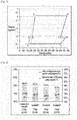
- FIG. 8 is a graph illustrating the rate of improvement in power consumption and the operation ratio of the freezing compartment of the cooling cycle.
- the comparative example indicates a conventional two-stage compression cooling cycle apparatus, and examples indicate the cooling cycle apparatus, equipped with the gas-liquid separator, the amount of refrigerant (gr) and cooling capacity of which are variously changed.
- the operation ratio of the freezing compartment is decreased by 0.6 - 1.3 %, and power consumption is decreased by 0.9 - 2.5 %, compared to the conventional apparatus.
- FIG. 9 is a graph illustrating the inputs of two compressors of the cooling cycle apparatus not being part of the invention.
- FIG. 10 is a graph illustrating the temperatures of the inlet and outlet of the second evaporator of the cooling cycle apparatus not being part of the invention.
- the difference between the inlet and outlet of the evaporator for the freezing compartment is 2.1 degrees in the case of the conventional apparatus but is decreased to 1.9 - 1.2 degrees.
- FIG. 11 is a graph illustrating pressure variation at higher pressure, medium pressure and lower pressure in the cooling cycle.
- the lower pressure signifies the minimum pressure before the compression of refrigerant
- the medium pressure signifies the pressure of the refrigerant which is firstly compressed in the lower-pressure compressor
- the higher pressure signifies the pressure of the refrigerant which is secondly compressed in the higher-pressure compressor.
Landscapes
- Engineering & Computer Science (AREA)
- Physics & Mathematics (AREA)
- Mechanical Engineering (AREA)
- Thermal Sciences (AREA)
- General Engineering & Computer Science (AREA)
- Chemical & Material Sciences (AREA)
- Combustion & Propulsion (AREA)
- Devices That Are Associated With Refrigeration Equipment (AREA)
- Analytical Chemistry (AREA)
- Power Engineering (AREA)
- Compression-Type Refrigeration Machines With Reversible Cycles (AREA)
Claims (5)
- Appareil à cycle de refroidissement pour un réfrigérateur, comprenant :un premier compresseur (110) destiné à comprimer un réfrigérant ;un condensateur (120) destiné à condenser le réfrigérant comprimé dans le premier compresseur (110) ;un premier dispositif de détente (140) destiné à réduire une température et une pression d'une partie du réfrigérant condensé dans le condensateur (120) ;un premier évaporateur (160) destiné à évaporer le réfrigérant ayant traversé le premier dispositif de détente (140) ;un deuxième dispositif de détente (150) destiné à réduire une température et une pression d'une partie restante du réfrigérant condensé dans le condensateur (120) ;un séparateur gaz-liquide (170) destiné à séparer un réfrigérant en phase liquide d'un réfrigérant en phase gazeuse dans le réfrigérant ayant traversé le deuxième dispositif de détente (150) ;un troisième dispositif de détente (240) destiné à réduire une température et une pression du réfrigérant en phase liquide séparé dans le séparateur gaz-liquide (170) ;un deuxième évaporateur (260) destiné à évaporer le réfrigérant ayant traversé le troisième dispositif de détente (240) ; etun deuxième compresseur (210) destiné à comprimer le réfrigérant ayant traversé le deuxième évaporateur (260) et à refouler le réfrigérant vers le premier compresseur (110),où le réfrigérant ayant traversé le premier évaporateur (160) et le réfrigérant en phase gazeuse séparé dans le séparateur gaz-liquide (170) sont introduits dans le premier compresseur (110) avec le réfrigérant comprimé dans le deuxième compresseur (210), caractérisé en ce que le réfrigérateur comprend en outreune unité d'échange de chaleur (300) prévue en aval du condensateur (120) de manière à échanger de la chaleur entre le réfrigérant en phase gazeuse ayant traversé le séparateur gaz-liquide (170) et le réfrigérant condensé dans le condensateur (120).
- Appareil à cycle de refroidissement selon la revendication 1, où le premier compresseur (110) comprime le réfrigérant à une pression supérieure à celle du deuxième compresseur (210).
- Appareil à cycle de refroidissement selon la revendication 1, où le troisième dispositif de détente (240) est plus court que le deuxième dispositif de détente (150).
- Appareil à cycle de refroidissement selon la revendication 1, où de l'air froid généré dans le premier évaporateur (160) est refoulé vers un compartiment de réfrigération, et de l'air froid généré dans le deuxième évaporateur (260) est refoulé vers un compartiment de congélation.
- Appareil à cycle de refroidissement selon l'une des revendications 1 à 4, comprenant en outre une vanne de commande (176) prévue dans un canal d'écoulement s'étendant du séparateur gaz-liquide (170) à un canal d'écoulement aval du premier évaporateur (160) au travers de l'unité d'échange de chaleur, et par lequel s'écoule le réfrigérant en phase gazeuse séparé dans le séparateur gaz-liquide (170), de manière à commander un degré d'ouverture du canal d'écoulement.
Applications Claiming Priority (2)
| Application Number | Priority Date | Filing Date | Title |
|---|---|---|---|
| KR1020150011348A KR102262722B1 (ko) | 2015-01-23 | 2015-01-23 | 냉장고용 냉각사이클장치 |
| PCT/KR2016/000667 WO2016117946A1 (fr) | 2015-01-23 | 2016-01-21 | Appareil à cycle de refroidissement pour réfrigérateur |
Publications (3)
| Publication Number | Publication Date |
|---|---|
| EP3090217A1 EP3090217A1 (fr) | 2016-11-09 |
| EP3090217A4 EP3090217A4 (fr) | 2018-01-24 |
| EP3090217B1 true EP3090217B1 (fr) | 2019-04-03 |
Family
ID=56417406
Family Applications (1)
| Application Number | Title | Priority Date | Filing Date |
|---|---|---|---|
| EP16724577.8A Active EP3090217B1 (fr) | 2015-01-23 | 2016-01-21 | Appareil à cycle de refroidissement pour réfrigérateur |
Country Status (4)
| Country | Link |
|---|---|
| US (1) | US10215469B2 (fr) |
| EP (1) | EP3090217B1 (fr) |
| KR (1) | KR102262722B1 (fr) |
| WO (1) | WO2016117946A1 (fr) |
Cited By (1)
| Publication number | Priority date | Publication date | Assignee | Title |
|---|---|---|---|---|
| CN112361634A (zh) * | 2020-12-14 | 2021-02-12 | 珠海格力电器股份有限公司 | 双级压缩制冷系统、制冷控制方法及制冷设备 |
Families Citing this family (16)
| Publication number | Priority date | Publication date | Assignee | Title |
|---|---|---|---|---|
| ITUA20163465A1 (it) * | 2016-05-16 | 2017-11-16 | Epta Spa | Impianto frigorifero a più livelli di evaporazione e metodo di gestione di un tale impianto |
| CN107421207A (zh) * | 2017-07-18 | 2017-12-01 | 李江 | 一种余热利用式制冷系统 |
| CN111801536B (zh) * | 2018-03-27 | 2023-04-28 | 比泽尔制冷设备有限公司 | 制冷设备 |
| JP2020034248A (ja) * | 2018-08-31 | 2020-03-05 | 三星電子株式会社Samsung Electronics Co.,Ltd. | 冷蔵庫 |
| CN115478918A (zh) * | 2019-06-13 | 2022-12-16 | 李华玉 | 逆向单工质蒸汽联合循环 |
| WO2020248588A1 (fr) * | 2019-06-14 | 2020-12-17 | 李华玉 | Cycle combiné de vapeur de milieu de travail unique inverse |
| WO2020248589A1 (fr) * | 2019-06-14 | 2020-12-17 | 李华玉 | Cycle combiné de vapeur de milieu de travail unique inversé |
| CN110411047B (zh) * | 2019-08-26 | 2024-09-24 | 珠海格力电器股份有限公司 | 制冷系统 |
| WO2021047125A1 (fr) * | 2019-09-10 | 2021-03-18 | 李华玉 | Cycle combiné de vapeur de milieu de travail unique inverse |
| CN110849035B (zh) * | 2019-11-18 | 2024-05-31 | 珠海格力电器股份有限公司 | 热泵系统、空调器及热泵系统的控制方法 |
| JP7052816B2 (ja) * | 2020-03-19 | 2022-04-12 | セイコーエプソン株式会社 | プロジェクター |
| JP2022070675A (ja) | 2020-10-27 | 2022-05-13 | セイコーエプソン株式会社 | プロジェクター |
| CN113915874A (zh) * | 2021-03-29 | 2022-01-11 | 海信(山东)冰箱有限公司 | 一种冰箱 |
| CN115307323B (zh) * | 2021-05-07 | 2025-05-02 | 天津柯德科技有限公司 | 一种可供多温区制冷的制冷系统 |
| EP4206562A1 (fr) * | 2021-12-30 | 2023-07-05 | Arçelik Anonim Sirketi | Dispositif de refroidissement |
| DE102023206969A1 (de) * | 2023-07-21 | 2025-01-23 | Siemens Energy Global GmbH & Co. KG | Wärmepumpenanordnung und Verfahren zum Betreiben einer Wärmepumpenanordnung |
Family Cites Families (11)
| Publication number | Priority date | Publication date | Assignee | Title |
|---|---|---|---|---|
| JPH1163694A (ja) * | 1997-08-21 | 1999-03-05 | Zexel Corp | 冷却サイクル |
| JP3630632B2 (ja) * | 2000-12-12 | 2005-03-16 | 株式会社東芝 | 冷蔵庫 |
| JP2003106693A (ja) | 2001-09-26 | 2003-04-09 | Toshiba Corp | 冷蔵庫 |
| US7770406B2 (en) | 2003-11-28 | 2010-08-10 | Kabushiki Kaisha Toshiba | Refrigerator |
| ES2652023T3 (es) | 2003-11-28 | 2018-01-31 | Mitsubishi Denki Kabushiki Kaisha | Congelador y acondicionador de aire |
| JP2006183950A (ja) | 2004-12-28 | 2006-07-13 | Sanyo Electric Co Ltd | 冷凍装置及び冷蔵庫 |
| JP4725449B2 (ja) | 2006-07-26 | 2011-07-13 | 株式会社デンソー | エジェクタ式冷凍サイクル |
| WO2008140454A1 (fr) * | 2007-05-14 | 2008-11-20 | Carrier Corporation | Système à compression à vapeur de réfrigérant ayant un économiseur à ballon de détente |
| JP2010038456A (ja) | 2008-08-05 | 2010-02-18 | Denso Corp | 蒸気圧縮式冷凍サイクル |
| KR20110072687A (ko) * | 2009-12-23 | 2011-06-29 | 주식회사 대우일렉트로닉스 | 냉장고 |
| US9146046B2 (en) * | 2010-07-28 | 2015-09-29 | Lg Electronics Inc. | Refrigerator and driving method thereof |
-
2015
- 2015-01-23 KR KR1020150011348A patent/KR102262722B1/ko active Active
-
2016
- 2016-01-21 US US15/029,235 patent/US10215469B2/en active Active
- 2016-01-21 EP EP16724577.8A patent/EP3090217B1/fr active Active
- 2016-01-21 WO PCT/KR2016/000667 patent/WO2016117946A1/fr not_active Ceased
Non-Patent Citations (1)
| Title |
|---|
| None * |
Cited By (1)
| Publication number | Priority date | Publication date | Assignee | Title |
|---|---|---|---|---|
| CN112361634A (zh) * | 2020-12-14 | 2021-02-12 | 珠海格力电器股份有限公司 | 双级压缩制冷系统、制冷控制方法及制冷设备 |
Also Published As
| Publication number | Publication date |
|---|---|
| EP3090217A4 (fr) | 2018-01-24 |
| US10215469B2 (en) | 2019-02-26 |
| KR102262722B1 (ko) | 2021-06-09 |
| KR20160091107A (ko) | 2016-08-02 |
| US20160356537A1 (en) | 2016-12-08 |
| EP3090217A1 (fr) | 2016-11-09 |
| WO2016117946A1 (fr) | 2016-07-28 |
Similar Documents
| Publication | Publication Date | Title |
|---|---|---|
| US10215469B2 (en) | Cooling cycle apparatus for refrigerator | |
| US7513128B2 (en) | Ejector-type cycle | |
| US10920760B2 (en) | Air compressor having an oil separator, an oil cooler, first and second evaporators, and wherein intake air and the oil are simultaneously cooled in the first and second evaporators | |
| CN111114244B (zh) | 用于机动车辆的气候控制系统的装置及操作该装置的方法 | |
| KR101173157B1 (ko) | 수냉식 응축기 및 과냉각용 수냉식 열교환기를 구비하는 차량용 공조 시스템 | |
| KR20110100905A (ko) | 칠러 | |
| CN103090602A (zh) | 非共沸混合制冷剂循环系统以及装配有其的制冷装置 | |
| CA3102260C (fr) | Systeme de refroidissement avec echangeur de chaleur de cote basse pression partiellement noye | |
| US20130055754A1 (en) | Air conditioner | |
| US20240093921A1 (en) | Cooling system with flooded low side heat exchangers | |
| KR101161381B1 (ko) | 냉동 사이클 장치 | |
| KR20200092604A (ko) | 공기조화기 | |
| KR102367790B1 (ko) | 냉각 효율 향상 기능을 갖는 터보 냉동기 | |
| CN110411047A (zh) | 制冷系统 | |
| US11365907B2 (en) | Refrigeration apparatus and liquid temperature control system | |
| CN214892088U (zh) | 用于冷藏冷冻装置的制冷系统及冷藏冷冻装置 | |
| JP2006003023A (ja) | 冷凍装置 | |
| KR20180056854A (ko) | 압축기의 흡입온도 조절이 가능한 고용량 급속 냉각 초저온 냉동기 | |
| CN113251681A (zh) | 带有多个吸热换热器的制冷系统 | |
| KR20210096521A (ko) | 공기 조화 장치 | |
| KR101743296B1 (ko) | 냉매시스템 | |
| US20160231063A1 (en) | Thermosyphon Configuration for Cascade Refrigeration Systems | |
| US20140208784A1 (en) | Refrigeration system with isentropic expansion nozzle | |
| KR20210041857A (ko) | 열교환기 | |
| CA3102922A1 (fr) | Appareil et procede de transfert de chaleur |
Legal Events
| Date | Code | Title | Description |
|---|---|---|---|
| PUAI | Public reference made under article 153(3) epc to a published international application that has entered the european phase |
Free format text: ORIGINAL CODE: 0009012 |
|
| 17P | Request for examination filed |
Effective date: 20160602 |
|
| AK | Designated contracting states |
Kind code of ref document: A1 Designated state(s): AL AT BE BG CH CY CZ DE DK EE ES FI FR GB GR HR HU IE IS IT LI LT LU LV MC MK MT NL NO PL PT RO RS SE SI SK SM TR |
|
| AX | Request for extension of the european patent |
Extension state: BA ME |
|
| STAA | Information on the status of an ep patent application or granted ep patent |
Free format text: STATUS: REQUEST FOR EXAMINATION WAS MADE |
|
| R17P | Request for examination filed (corrected) |
Effective date: 20160602 |
|
| A4 | Supplementary search report drawn up and despatched |
Effective date: 20180102 |
|
| RIC1 | Information provided on ipc code assigned before grant |
Ipc: F25B 1/10 20060101ALI20171219BHEP Ipc: F25B 40/00 20060101ALI20171219BHEP Ipc: F25D 11/02 20060101ALI20171219BHEP Ipc: F25B 5/02 20060101AFI20171219BHEP Ipc: F25B 40/04 20060101ALI20171219BHEP Ipc: F25B 40/02 20060101ALI20171219BHEP |
|
| DAV | Request for validation of the european patent (deleted) | ||
| DAX | Request for extension of the european patent (deleted) | ||
| GRAP | Despatch of communication of intention to grant a patent |
Free format text: ORIGINAL CODE: EPIDOSNIGR1 |
|
| STAA | Information on the status of an ep patent application or granted ep patent |
Free format text: STATUS: GRANT OF PATENT IS INTENDED |
|
| INTG | Intention to grant announced |
Effective date: 20181012 |
|
| GRAS | Grant fee paid |
Free format text: ORIGINAL CODE: EPIDOSNIGR3 |
|
| GRAA | (expected) grant |
Free format text: ORIGINAL CODE: 0009210 |
|
| STAA | Information on the status of an ep patent application or granted ep patent |
Free format text: STATUS: THE PATENT HAS BEEN GRANTED |
|
| AK | Designated contracting states |
Kind code of ref document: B1 Designated state(s): AL AT BE BG CH CY CZ DE DK EE ES FI FR GB GR HR HU IE IS IT LI LT LU LV MC MK MT NL NO PL PT RO RS SE SI SK SM TR |
|
| REG | Reference to a national code |
Ref country code: GB Ref legal event code: FG4D |
|
| REG | Reference to a national code |
Ref country code: CH Ref legal event code: EP Ref country code: AT Ref legal event code: REF Ref document number: 1116224 Country of ref document: AT Kind code of ref document: T Effective date: 20190415 |
|
| REG | Reference to a national code |
Ref country code: DE Ref legal event code: R096 Ref document number: 602016011924 Country of ref document: DE |
|
| REG | Reference to a national code |
Ref country code: IE Ref legal event code: FG4D |
|
| REG | Reference to a national code |
Ref country code: NL Ref legal event code: MP Effective date: 20190403 |
|
| REG | Reference to a national code |
Ref country code: LT Ref legal event code: MG4D |
|
| REG | Reference to a national code |
Ref country code: AT Ref legal event code: MK05 Ref document number: 1116224 Country of ref document: AT Kind code of ref document: T Effective date: 20190403 |
|
| PG25 | Lapsed in a contracting state [announced via postgrant information from national office to epo] |
Ref country code: NL Free format text: LAPSE BECAUSE OF FAILURE TO SUBMIT A TRANSLATION OF THE DESCRIPTION OR TO PAY THE FEE WITHIN THE PRESCRIBED TIME-LIMIT Effective date: 20190403 |
|
| PG25 | Lapsed in a contracting state [announced via postgrant information from national office to epo] |
Ref country code: LT Free format text: LAPSE BECAUSE OF FAILURE TO SUBMIT A TRANSLATION OF THE DESCRIPTION OR TO PAY THE FEE WITHIN THE PRESCRIBED TIME-LIMIT Effective date: 20190403 Ref country code: NO Free format text: LAPSE BECAUSE OF FAILURE TO SUBMIT A TRANSLATION OF THE DESCRIPTION OR TO PAY THE FEE WITHIN THE PRESCRIBED TIME-LIMIT Effective date: 20190703 Ref country code: HR Free format text: LAPSE BECAUSE OF FAILURE TO SUBMIT A TRANSLATION OF THE DESCRIPTION OR TO PAY THE FEE WITHIN THE PRESCRIBED TIME-LIMIT Effective date: 20190403 Ref country code: CZ Free format text: LAPSE BECAUSE OF FAILURE TO SUBMIT A TRANSLATION OF THE DESCRIPTION OR TO PAY THE FEE WITHIN THE PRESCRIBED TIME-LIMIT Effective date: 20190403 Ref country code: ES Free format text: LAPSE BECAUSE OF FAILURE TO SUBMIT A TRANSLATION OF THE DESCRIPTION OR TO PAY THE FEE WITHIN THE PRESCRIBED TIME-LIMIT Effective date: 20190403 Ref country code: SE Free format text: LAPSE BECAUSE OF FAILURE TO SUBMIT A TRANSLATION OF THE DESCRIPTION OR TO PAY THE FEE WITHIN THE PRESCRIBED TIME-LIMIT Effective date: 20190403 Ref country code: PT Free format text: LAPSE BECAUSE OF FAILURE TO SUBMIT A TRANSLATION OF THE DESCRIPTION OR TO PAY THE FEE WITHIN THE PRESCRIBED TIME-LIMIT Effective date: 20190803 Ref country code: AL Free format text: LAPSE BECAUSE OF FAILURE TO SUBMIT A TRANSLATION OF THE DESCRIPTION OR TO PAY THE FEE WITHIN THE PRESCRIBED TIME-LIMIT Effective date: 20190403 Ref country code: FI Free format text: LAPSE BECAUSE OF FAILURE TO SUBMIT A TRANSLATION OF THE DESCRIPTION OR TO PAY THE FEE WITHIN THE PRESCRIBED TIME-LIMIT Effective date: 20190403 |
|
| PG25 | Lapsed in a contracting state [announced via postgrant information from national office to epo] |
Ref country code: BG Free format text: LAPSE BECAUSE OF FAILURE TO SUBMIT A TRANSLATION OF THE DESCRIPTION OR TO PAY THE FEE WITHIN THE PRESCRIBED TIME-LIMIT Effective date: 20190703 Ref country code: PL Free format text: LAPSE BECAUSE OF FAILURE TO SUBMIT A TRANSLATION OF THE DESCRIPTION OR TO PAY THE FEE WITHIN THE PRESCRIBED TIME-LIMIT Effective date: 20190403 Ref country code: GR Free format text: LAPSE BECAUSE OF FAILURE TO SUBMIT A TRANSLATION OF THE DESCRIPTION OR TO PAY THE FEE WITHIN THE PRESCRIBED TIME-LIMIT Effective date: 20190704 Ref country code: LV Free format text: LAPSE BECAUSE OF FAILURE TO SUBMIT A TRANSLATION OF THE DESCRIPTION OR TO PAY THE FEE WITHIN THE PRESCRIBED TIME-LIMIT Effective date: 20190403 Ref country code: RS Free format text: LAPSE BECAUSE OF FAILURE TO SUBMIT A TRANSLATION OF THE DESCRIPTION OR TO PAY THE FEE WITHIN THE PRESCRIBED TIME-LIMIT Effective date: 20190403 |
|
| PG25 | Lapsed in a contracting state [announced via postgrant information from national office to epo] |
Ref country code: AT Free format text: LAPSE BECAUSE OF FAILURE TO SUBMIT A TRANSLATION OF THE DESCRIPTION OR TO PAY THE FEE WITHIN THE PRESCRIBED TIME-LIMIT Effective date: 20190403 Ref country code: IS Free format text: LAPSE BECAUSE OF FAILURE TO SUBMIT A TRANSLATION OF THE DESCRIPTION OR TO PAY THE FEE WITHIN THE PRESCRIBED TIME-LIMIT Effective date: 20190803 |
|
| REG | Reference to a national code |
Ref country code: DE Ref legal event code: R097 Ref document number: 602016011924 Country of ref document: DE |
|
| PG25 | Lapsed in a contracting state [announced via postgrant information from national office to epo] |
Ref country code: SK Free format text: LAPSE BECAUSE OF FAILURE TO SUBMIT A TRANSLATION OF THE DESCRIPTION OR TO PAY THE FEE WITHIN THE PRESCRIBED TIME-LIMIT Effective date: 20190403 Ref country code: RO Free format text: LAPSE BECAUSE OF FAILURE TO SUBMIT A TRANSLATION OF THE DESCRIPTION OR TO PAY THE FEE WITHIN THE PRESCRIBED TIME-LIMIT Effective date: 20190403 Ref country code: DK Free format text: LAPSE BECAUSE OF FAILURE TO SUBMIT A TRANSLATION OF THE DESCRIPTION OR TO PAY THE FEE WITHIN THE PRESCRIBED TIME-LIMIT Effective date: 20190403 Ref country code: EE Free format text: LAPSE BECAUSE OF FAILURE TO SUBMIT A TRANSLATION OF THE DESCRIPTION OR TO PAY THE FEE WITHIN THE PRESCRIBED TIME-LIMIT Effective date: 20190403 |
|
| PLBE | No opposition filed within time limit |
Free format text: ORIGINAL CODE: 0009261 |
|
| STAA | Information on the status of an ep patent application or granted ep patent |
Free format text: STATUS: NO OPPOSITION FILED WITHIN TIME LIMIT |
|
| PG25 | Lapsed in a contracting state [announced via postgrant information from national office to epo] |
Ref country code: SM Free format text: LAPSE BECAUSE OF FAILURE TO SUBMIT A TRANSLATION OF THE DESCRIPTION OR TO PAY THE FEE WITHIN THE PRESCRIBED TIME-LIMIT Effective date: 20190403 Ref country code: IT Free format text: LAPSE BECAUSE OF FAILURE TO SUBMIT A TRANSLATION OF THE DESCRIPTION OR TO PAY THE FEE WITHIN THE PRESCRIBED TIME-LIMIT Effective date: 20190403 |
|
| 26N | No opposition filed |
Effective date: 20200106 |
|
| PG25 | Lapsed in a contracting state [announced via postgrant information from national office to epo] |
Ref country code: TR Free format text: LAPSE BECAUSE OF FAILURE TO SUBMIT A TRANSLATION OF THE DESCRIPTION OR TO PAY THE FEE WITHIN THE PRESCRIBED TIME-LIMIT Effective date: 20190403 |
|
| PG25 | Lapsed in a contracting state [announced via postgrant information from national office to epo] |
Ref country code: SI Free format text: LAPSE BECAUSE OF FAILURE TO SUBMIT A TRANSLATION OF THE DESCRIPTION OR TO PAY THE FEE WITHIN THE PRESCRIBED TIME-LIMIT Effective date: 20190403 |
|
| PG25 | Lapsed in a contracting state [announced via postgrant information from national office to epo] |
Ref country code: MC Free format text: LAPSE BECAUSE OF FAILURE TO SUBMIT A TRANSLATION OF THE DESCRIPTION OR TO PAY THE FEE WITHIN THE PRESCRIBED TIME-LIMIT Effective date: 20190403 |
|
| REG | Reference to a national code |
Ref country code: CH Ref legal event code: PL |
|
| GBPC | Gb: european patent ceased through non-payment of renewal fee |
Effective date: 20200121 |
|
| REG | Reference to a national code |
Ref country code: BE Ref legal event code: MM Effective date: 20200131 |
|
| PG25 | Lapsed in a contracting state [announced via postgrant information from national office to epo] |
Ref country code: GB Free format text: LAPSE BECAUSE OF NON-PAYMENT OF DUE FEES Effective date: 20200121 Ref country code: LU Free format text: LAPSE BECAUSE OF NON-PAYMENT OF DUE FEES Effective date: 20200121 Ref country code: FR Free format text: LAPSE BECAUSE OF NON-PAYMENT OF DUE FEES Effective date: 20200131 |
|
| PG25 | Lapsed in a contracting state [announced via postgrant information from national office to epo] |
Ref country code: CH Free format text: LAPSE BECAUSE OF NON-PAYMENT OF DUE FEES Effective date: 20200131 Ref country code: BE Free format text: LAPSE BECAUSE OF NON-PAYMENT OF DUE FEES Effective date: 20200131 Ref country code: LI Free format text: LAPSE BECAUSE OF NON-PAYMENT OF DUE FEES Effective date: 20200131 |
|
| PG25 | Lapsed in a contracting state [announced via postgrant information from national office to epo] |
Ref country code: IE Free format text: LAPSE BECAUSE OF NON-PAYMENT OF DUE FEES Effective date: 20200121 |
|
| PG25 | Lapsed in a contracting state [announced via postgrant information from national office to epo] |
Ref country code: MT Free format text: LAPSE BECAUSE OF FAILURE TO SUBMIT A TRANSLATION OF THE DESCRIPTION OR TO PAY THE FEE WITHIN THE PRESCRIBED TIME-LIMIT Effective date: 20190403 Ref country code: CY Free format text: LAPSE BECAUSE OF FAILURE TO SUBMIT A TRANSLATION OF THE DESCRIPTION OR TO PAY THE FEE WITHIN THE PRESCRIBED TIME-LIMIT Effective date: 20190403 |
|
| PG25 | Lapsed in a contracting state [announced via postgrant information from national office to epo] |
Ref country code: MK Free format text: LAPSE BECAUSE OF FAILURE TO SUBMIT A TRANSLATION OF THE DESCRIPTION OR TO PAY THE FEE WITHIN THE PRESCRIBED TIME-LIMIT Effective date: 20190403 |
|
| PGFP | Annual fee paid to national office [announced via postgrant information from national office to epo] |
Ref country code: DE Payment date: 20251208 Year of fee payment: 11 |