EP3090316B1 - Freihändige schnittstelle - Google Patents
Freihändige schnittstelle Download PDFInfo
- Publication number
- EP3090316B1 EP3090316B1 EP14877390.6A EP14877390A EP3090316B1 EP 3090316 B1 EP3090316 B1 EP 3090316B1 EP 14877390 A EP14877390 A EP 14877390A EP 3090316 B1 EP3090316 B1 EP 3090316B1
- Authority
- EP
- European Patent Office
- Prior art keywords
- level
- radiant energy
- received
- change
- indicative
- Prior art date
- Legal status (The legal status is an assumption and is not a legal conclusion. Google has not performed a legal analysis and makes no representation as to the accuracy of the status listed.)
- Active
Links
Images




Classifications
-
- A—HUMAN NECESSITIES
- A61—MEDICAL OR VETERINARY SCIENCE; HYGIENE
- A61B—DIAGNOSIS; SURGERY; IDENTIFICATION
- A61B5/00—Measuring for diagnostic purposes; Identification of persons
- A61B5/0002—Remote monitoring of patients using telemetry, e.g. transmission of vital signals via a communication network
- A61B5/0026—Remote monitoring of patients using telemetry, e.g. transmission of vital signals via a communication network characterised by the transmission medium
-
- A—HUMAN NECESSITIES
- A61—MEDICAL OR VETERINARY SCIENCE; HYGIENE
- A61B—DIAGNOSIS; SURGERY; IDENTIFICATION
- A61B5/00—Measuring for diagnostic purposes; Identification of persons
- A61B5/0002—Remote monitoring of patients using telemetry, e.g. transmission of vital signals via a communication network
- A61B5/0015—Remote monitoring of patients using telemetry, e.g. transmission of vital signals via a communication network characterised by features of the telemetry system
-
- A—HUMAN NECESSITIES
- A61—MEDICAL OR VETERINARY SCIENCE; HYGIENE
- A61B—DIAGNOSIS; SURGERY; IDENTIFICATION
- A61B5/00—Measuring for diagnostic purposes; Identification of persons
- A61B5/103—Measuring devices for testing the shape, pattern, colour, size or movement of the body or parts thereof, for diagnostic purposes
- A61B5/11—Measuring movement of the entire body or parts thereof, e.g. head or hand tremor or mobility of a limb
- A61B5/1126—Measuring movement of the entire body or parts thereof, e.g. head or hand tremor or mobility of a limb using a particular sensing technique
-
- A—HUMAN NECESSITIES
- A61—MEDICAL OR VETERINARY SCIENCE; HYGIENE
- A61B—DIAGNOSIS; SURGERY; IDENTIFICATION
- A61B5/00—Measuring for diagnostic purposes; Identification of persons
- A61B5/145—Measuring characteristics of blood in vivo, e.g. gas concentration or pH-value ; Measuring characteristics of body fluids or tissues, e.g. interstitial fluid or cerebral tissue
- A61B5/14532—Measuring characteristics of blood in vivo, e.g. gas concentration or pH-value ; Measuring characteristics of body fluids or tissues, e.g. interstitial fluid or cerebral tissue for measuring glucose, e.g. by tissue impedance measurement
-
- A—HUMAN NECESSITIES
- A61—MEDICAL OR VETERINARY SCIENCE; HYGIENE
- A61B—DIAGNOSIS; SURGERY; IDENTIFICATION
- A61B5/00—Measuring for diagnostic purposes; Identification of persons
- A61B5/145—Measuring characteristics of blood in vivo, e.g. gas concentration or pH-value ; Measuring characteristics of body fluids or tissues, e.g. interstitial fluid or cerebral tissue
- A61B5/14546—Measuring characteristics of blood in vivo, e.g. gas concentration or pH-value ; Measuring characteristics of body fluids or tissues, e.g. interstitial fluid or cerebral tissue for measuring analytes not otherwise provided for, e.g. ions, cytochromes
-
- A—HUMAN NECESSITIES
- A61—MEDICAL OR VETERINARY SCIENCE; HYGIENE
- A61B—DIAGNOSIS; SURGERY; IDENTIFICATION
- A61B5/00—Measuring for diagnostic purposes; Identification of persons
- A61B5/145—Measuring characteristics of blood in vivo, e.g. gas concentration or pH-value ; Measuring characteristics of body fluids or tissues, e.g. interstitial fluid or cerebral tissue
- A61B5/1468—Measuring characteristics of blood in vivo, e.g. gas concentration or pH-value ; Measuring characteristics of body fluids or tissues, e.g. interstitial fluid or cerebral tissue using chemical or electrochemical methods, e.g. by polarographic means
-
- A—HUMAN NECESSITIES
- A61—MEDICAL OR VETERINARY SCIENCE; HYGIENE
- A61B—DIAGNOSIS; SURGERY; IDENTIFICATION
- A61B5/00—Measuring for diagnostic purposes; Identification of persons
- A61B5/68—Arrangements of detecting, measuring or recording means, e.g. sensors, in relation to patient
- A61B5/6801—Arrangements of detecting, measuring or recording means, e.g. sensors, in relation to patient specially adapted to be attached to or worn on the body surface
- A61B5/6813—Specially adapted to be attached to a specific body part
- A61B5/6814—Head
- A61B5/6821—Eye
-
- G—PHYSICS
- G06—COMPUTING OR CALCULATING; COUNTING
- G06F—ELECTRIC DIGITAL DATA PROCESSING
- G06F3/00—Input arrangements for transferring data to be processed into a form capable of being handled by the computer; Output arrangements for transferring data from processing unit to output unit, e.g. interface arrangements
- G06F3/01—Input arrangements or combined input and output arrangements for interaction between user and computer
- G06F3/011—Arrangements for interaction with the human body, e.g. for user immersion in virtual reality
- G06F3/013—Eye tracking input arrangements
-
- G—PHYSICS
- G06—COMPUTING OR CALCULATING; COUNTING
- G06F—ELECTRIC DIGITAL DATA PROCESSING
- G06F3/00—Input arrangements for transferring data to be processed into a form capable of being handled by the computer; Output arrangements for transferring data from processing unit to output unit, e.g. interface arrangements
- G06F3/01—Input arrangements or combined input and output arrangements for interaction between user and computer
- G06F3/017—Gesture based interaction, e.g. based on a set of recognized hand gestures
-
- A—HUMAN NECESSITIES
- A61—MEDICAL OR VETERINARY SCIENCE; HYGIENE
- A61B—DIAGNOSIS; SURGERY; IDENTIFICATION
- A61B2560/00—Constructional details of operational features of apparatus; Accessories for medical measuring apparatus
- A61B2560/02—Operational features
- A61B2560/0204—Operational features of power management
-
- A—HUMAN NECESSITIES
- A61—MEDICAL OR VETERINARY SCIENCE; HYGIENE
- A61B—DIAGNOSIS; SURGERY; IDENTIFICATION
- A61B2560/00—Constructional details of operational features of apparatus; Accessories for medical measuring apparatus
- A61B2560/02—Operational features
- A61B2560/0204—Operational features of power management
- A61B2560/0214—Operational features of power management of power generation or supply
-
- A—HUMAN NECESSITIES
- A61—MEDICAL OR VETERINARY SCIENCE; HYGIENE
- A61B—DIAGNOSIS; SURGERY; IDENTIFICATION
- A61B2560/00—Constructional details of operational features of apparatus; Accessories for medical measuring apparatus
- A61B2560/04—Constructional details of apparatus
- A61B2560/0487—Special user inputs or interfaces
-
- A—HUMAN NECESSITIES
- A61—MEDICAL OR VETERINARY SCIENCE; HYGIENE
- A61B—DIAGNOSIS; SURGERY; IDENTIFICATION
- A61B2562/00—Details of sensors; Constructional details of sensor housings or probes; Accessories for sensors
- A61B2562/16—Details of sensor housings or probes; Details of structural supports for sensors
- A61B2562/164—Details of sensor housings or probes; Details of structural supports for sensors the sensor is mounted in or on a conformable substrate or carrier
-
- A—HUMAN NECESSITIES
- A61—MEDICAL OR VETERINARY SCIENCE; HYGIENE
- A61B—DIAGNOSIS; SURGERY; IDENTIFICATION
- A61B2562/00—Details of sensors; Constructional details of sensor housings or probes; Accessories for sensors
- A61B2562/16—Details of sensor housings or probes; Details of structural supports for sensors
- A61B2562/166—Details of sensor housings or probes; Details of structural supports for sensors the sensor is mounted on a specially adapted printed circuit board
Definitions
- One type of wearable device has control electronics and an antenna embedded therein.
- An external reader may be configured to transmit radio frequency (RF) energy to the wearable device so as to provide power to the wearable device.
- the combination of the control electronics and the antenna may be configured to receive such RF energy transmitted by the external reader and modify the impedance of the antenna so as to characteristically modify the backscatter from the antenna. In this way, the wearable device may communicate back to external reader.
- RF radio frequency
- US 2012/281181 A1 discloses methods of eye gaze tracking using magnetized contact lenses tracked by magnetic sensors and/or reflecting contact lenses tracked by video-based sensors. Tracking information of contact lenses from magnetic sensors and video-based sensors may be used to improve eye tracking and/or combined with other sensor data to improve accuracy. Furthermore, reflective contact lenses can improve blink detection while eye gaze tracking is otherwise unimpeded by magnetized contact lenses.
- Some embodiments of the present disclosure provide a method including a wearable device receiving a level of radiant energy, detecting a change in the received level of radiant energy, determining that the detected change in the received level of radiant energy is indicative of a predetermined pattern of received radiant energy indicative of at least a body movement, and responsively transmitting to an external reader an instruction that indicates that the wearable device has determined that the detected change in the received level of radiant energy is indicative of a predetermined pattern of received radiant energy.
- Some embodiments of the present disclosure provide a method including a reader device transmitting to a wearable device radiant energy, receiving from the wearable device one or more signals indicative of a change in a received level of radiant energy, determining that the change in the received level of radiant energy is indicative of a predetermined pattern of received radiant energy indicative of at least a body movement, and operating at least one external device.
- Some embodiments of the present disclosure provide a system that includes a wearable device with an antenna, and a reader device.
- the wearable device is configured to receive a level of radiant energy, detect a change in the received level of radiant energy, determine that the detected change is indicative of a predetermined pattern of received radiant energy indicative of at least one body movement, and in response to the determining, operate the antenna to transmit to the reader device an instruction that indicates that the wearable device has determined that the detected change in the received level of radiant energy is indicative of a predetermined pattern of received radiant energy.
- the reader device is configured to receive the instruction from the wearable device, and in response to the receiving, operate at least one external device.
- a wearable device can include at least one sensor, control electronics, and an antenna embedded in a polymeric material formed to be contact mounted to an eye.
- the wearable device may be arranged to wirelessly communicate to an external reader via the antenna.
- the polymeric material can be in the form of a round lens with a concave curvature configured to mount to a corneal surface of an eye.
- the electronics can be embedded on a substrate located near the periphery of the polymeric material to avoid interference with vision. In some examples, the electronics are entirely embedded within the contact lens material.
- the antenna can be suspended in the lens material and situated such that it is less than about 10 micrometers from the polymeric surface configured to mount to the cornea.
- the wearable device can be powered via radiated energy harvested by the antenna.
- Power can be provided by light energizing photovoltaic cells included on the sensing platform. Additionally or alternatively, power can be provided by radio frequency energy harvested from the antenna.
- a rectifier and/or regulator can be incorporated with the control electronics to generate a stable DC voltage to power the control electronics from the harvested energy.
- the antenna can be arranged as a loop of conductive material with leads connected to the control electronics. In some embodiments, such a loop antenna can wirelessly communicate to an external reader by modifying the impedance of the loop antenna so as to modify backscatter radiation from the antenna.
- the senor can be an electrochemical sensor configured for measuring analyte concentration in tear fluid.
- tear fluid contains a variety of inorganic electrolytes (e.g., Ca 2+ , Mg 2+ , Cl - ), organic components (e.g., glucose, lactate, proteins, lipids, etc.), and so on that can be used to diagnose health states.
- the sensor can be a part of a sensing platform that is arranged to measure one or more of these components and provide a convenient non-invasive platform to determine health-related parameters.
- the sensing platform can be arranged to sense glucose and be used to measure glucose levels in diabetic patients.
- the wearable device may be configured to recognize a user gesture (e.g., a blink, a head nod, a change of direction of a gaze, or any other similar body movement or pattern of body movements) as an intention to operate an external device in some way. Responsively, the wearable device may transmit a signal to the external reader indicating such an intention. The external reader may, as a result, operate an external device (e.g., a personal computer, tablet computer, cell phone, video game console, television, etc.) in some way.
- a user gesture e.g., a blink, a head nod, a change of direction of a gaze, or any other similar body movement or pattern of body movements
- a user gesture e.g., a blink, a head nod, a change of direction of a gaze, or any other similar body movement or pattern of body movements
- the wearable device may transmit a signal to the external reader indicating such an intention.
- the external reader may, as a result, operate an external device
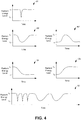
- the wearable device may detect a blink when the level of detected radiant energy very briefly drops below a particular threshold level and then quickly returns to its previous level.
- the wearable device may detect a head nod when the level of detected radiant energy changes relatively slowly from a first level to a second level and then slowly returns to the first level.
- the wearable device may detect a change of gaze when the level of detected radiant energy changes from a first level to a second level and then remains at the second level for at least a threshold period of time.
- Other ways of detecting user gestures based on the change of detected radiant energy levels are possible as well.
- the external reader may be configured to recognize a user gesture based on signals transmitted by the wearable device. For instance, in some examples, the wearable device may be configured to transmit to the external reader an indication of the detected levels of radiant energy received at the wearable device. In the same way the wearable device itself may recognize user gestures as described above, the external reader may recognize user gestures based on detected changes in the levels of radiant energy received at and subsequently indicated by the wearable device. In response to detecting a single user gesture, or, in some cases, a pattern of user gestures, the external reader may operate an external device.
- an auxiliary device may be configured to recognize a user gesture based on inductive position sensing of the wearable device (e.g., an eye-mountable device) and responsively transmit to the external reader an indication of the user gesture.
- an inductive sensor may be positioned within a pair of glasses (or other head-mounted device). Movement of the eye-mountable device with respect to the inductive sensor, such as when the eye moves, may cause a change in the inductance of the inductive sensor.
- the auxiliary device may recognize when the inductance changes according to a predetermined pattern (such as an oscillating pattern or some other type of repeating pattern) and responsively transmit to the external reader an instruction to operate an external device.
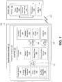
- the antenna 170, the controller 150, the power supply 140, and the auxiliary electronics 160 can all be situated on the embedded substrate 130. Because the eye-mountable device 110 includes electronics and is configured to be contact-mounted to an eye, it is also referred to herein as an ophthalmic electronics platform.
- the polymeric material 120 can have a concave surface configured to adhere (“mount") to a moistened corneal surface (e.g., by capillary forces with a tear film coating the corneal surface). Additionally or alternatively, the eye-mountable device 110 can be adhered by a vacuum force between the corneal surface and the polymeric material due to the concave curvature. While mounted with the concave surface against the eye, the outward-facing surface of the polymeric material 120 can have a convex curvature that is formed to not interfere with eye-lid motion while the eye-mountable device 110 is mounted to the eye.
- the polymeric material 120 can be a substantially transparent curved polymeric disk shaped similarly to a contact lens.
- the substrate 130 includes one or more surfaces suitable for mounting the auxiliary electronics 160, the controller 150, the power supply 140, and the antenna 170.
- the substrate 130 can be employed both as a mounting platform for chip-based circuitry (e.g., by flip-chip mounting) and/or as a platform for patterning conductive materials (e.g., gold, platinum, palladium, titanium, copper, aluminum, silver, metals, other conductive materials, combinations of these, etc. to create electrodes, interconnects, antennae, etc.
- substantially transparent conductive materials e.g ., indium tin oxide
- the antenna 170 can be formed by depositing a pattern of gold or another conductive material on the substrate 130.
- interconnects 151, 157 between the controller 150 and the auxiliary electronics 160, and between the controller 150 and the antenna 170, respectively, can be formed by depositing suitable patterns of conductive materials on the substrate 130.
- a combination of resists, masks, and deposition techniques can be employed to pattern materials on the substrate 130.
- the substrate 130 can be a relatively rigid material, such as polyethylene terephthalate (“PET”) or another material sufficient to structurally support the circuitry and/or electronics within the polymeric material 120.
- PET polyethylene terephthalate
- the eye-mountable device 110 can alternatively be arranged with a group of unconnected substrates rather than a single substrate.
- the controller 150 and a light sensor or other auxiliary electronic component can be mounted to one substrate, while the antenna 170 is mounted to another substrate and the two can be electrically connected via the interconnects 157.
- auxiliary electronics 160 (and the substrate 130) can be positioned away from the center of the eye-mountable device 110 and thereby avoid interference with light transmission to the eye through the center of the eye-mountable device 110.
- the substrate 130 can be embedded around the periphery ( e.g ., near the outer circumference) of the disk.
- the auxiliary electronics 160 (and the substrate 130) can be positioned in the center region of the eye-mountable device 110.
- the auxiliary electronics 160 and/or substrate 130 can be substantially transparent to incoming visible light to mitigate interference with light transmission to the eye.
- the auxiliary electronics 160 can include an ambient light sensor 164 that operates to detect the level of ambient light incident on the eye-mountable device 110.
- the auxiliary electronics 160 may also include an analyte bio-sensor 162.
- Auxiliary electronics 160 may include other electronics as well.
- the substrate 130 can be shaped as a flattened ring with a radial width dimension sufficient to provide a mounting platform for the embedded electronics components.
- the substrate 130 can have a thickness sufficiently small to allow the substrate 130 to be embedded in the polymeric material 120 without influencing the profile of the eye-mountable device 110.
- the substrate 130 can have a thickness sufficiently large to provide structural stability suitable for supporting the electronics mounted thereon.
- the substrate 130 can be shaped as a ring with a diameter of about 10 millimeters, a radial width of about 1 millimeter ( e.g ., an outer radius 1 millimeter larger than an inner radius), and a thickness of about 50 micrometers.
- the substrate 130 can optionally be aligned with the curvature of the eye-mounting surface of the eye-mountable device 110 (e.g ., convex surface).
- the substrate 130 can be shaped along the surface of an imaginary cone between two circular segments that define an inner radius and an outer radius.
- the surface of the substrate 130 along the surface of the imaginary cone defines an inclined surface that is approximately aligned with the curvature of the eye mounting surface at that radius.
- the power supply 140 is configured to harvest ambient energy to power the controller 150 and auxiliary electronics 160.
- a radio-frequency energy-harvesting antenna 142 can capture energy from incident radio radiation.
- solar cell(s) 144 (“photovoltaic cells”) can capture energy from incoming ultraviolet, visible, and/or infrared radiation.
- an inertial power scavenging system can be included to capture energy from ambient vibrations.
- the energy harvesting antenna 142 can optionally be a dual-purpose antenna that is also used to communicate information to the external reader 180. That is, the functions of the communication antenna 170 and the energy harvesting antenna 142 can be accomplished with the same physical antenna.
- a rectifier/regulator 146 can be used to condition the captured energy to a stable DC supply voltage 141 that is supplied to the controller 150.
- the energy harvesting antenna 142 can receive incident radio frequency radiation. Varying electrical signals on the leads of the antenna 142 are output to the rectifier/regulator 146.
- the rectifier/regulator 146 rectifies the varying electrical signals to a DC voltage and regulates the rectified DC voltage to a level suitable for operating the controller 150. Additionally or alternatively, output voltage from the solar cell(s) 144 can be regulated to a level suitable for operating the controller 150.
- the rectifier/regulator 146 can include one or more energy storage devices to mitigate high frequency variations in the ambient energy gathering antenna 142 and/or solar cell(s) 144. For example, one or more energy storage devices (e.g. , a capacitor, an inductor, etc.) can be connected in parallel across the outputs of the rectifier 146 to regulate the DC supply voltage 141 and function as a low-pass filter.
- the controller 150 is turned on when the DC supply voltage 141 is provided to the controller 150, and the logic in the controller 150 operates the auxiliary electronics 160 and the antenna 170.
- the controller 150 can include logic circuitry configured to operate the auxiliary electronics 160 so as to interact with a biological environment of the eye-mountable device 110 or take an ambient-light reading. The interaction could involve the use of one or more components, such an analyte bio-sensor 162, in auxiliary electronics 160 to obtain input from the biological environment.
- the controller 150 includes a sensor interface module 152 that is configured to operate analyte bio-sensor 162.
- the analyte bio-sensor 162 can be, for example, an amperometric electrochemical sensor that includes a working electrode and a reference electrode.
- a voltage can be applied between the working and reference electrodes to cause an analyte to undergo an electrochemical reaction (e.g., a reduction and/or oxidation reaction) at the working electrode.
- the electrochemical reaction can generate an amperometric current that can be measured through the working electrode.
- the amperometric current can be dependent on the analyte concentration.
- the amount of the amperometric current that is measured through the working electrode can provide an indication of analyte concentration.
- the sensor interface module 152 can be a potentiostat configured to apply a voltage difference between working and reference electrodes while measuring a current through the working electrode.
- the controller 150 can also include a communication circuit 156 for sending and/or receiving information via the antenna 170.
- the communication circuit 156 can optionally include one or more oscillators, mixers, frequency injectors, etc. to modulate and/or demodulate information on a carrier frequency to be transmitted and/or received by the antenna 170.
- the eye-mountable device 110 is configured to indicate an output from a bio-sensor by modulating an impedance of the antenna 170 in a manner that is perceivably by the external reader 180.
- the communication circuit 156 can cause variations in the amplitude, phase, and/or frequency of backscatter radiation from the antenna 170, and such variations can be detected by the reader 180.
- the controller 150 is connected to the auxiliary electronics 160 via interconnects 151.
- a patterned conductive material e.g ., gold, platinum, palladium, titanium, copper, aluminum, silver, metals, combinations of these, etc.
- the controller 150 is connected to the antenna 170 via interconnects 157.
- the block diagram shown in Figure 1 is described in connection with functional modules for convenience in description.
- embodiments of the eye-mountable device 110 can be arranged with one or more of the functional modules ("sub-systems") implemented in a single chip, integrated circuit, and/or physical feature.
- the rectifier/regulator 146 is illustrated in the power supply block 140, the rectifier/regulator 146 can be implemented in a chip that also includes the logic elements of the controller 150 and/or other features of the embedded electronics in the eye-mountable device 110.
- the DC supply voltage 141 that is provided to the controller 150 from the power supply 140 can be a supply voltage that is provided on a chip by rectifier and/or regulator components the same chip. That is, the functional blocks in Figure 1 shown as the power supply block 140 and controller block 150 need not be implemented as separated modules.
- one or more of the functional modules described in Figure 1 can be implemented by separately packaged chips electrically connected to one another.
- the energy harvesting antenna 142 and the communication antenna 170 can be implemented with the same physical antenna.
- a loop antenna can both harvest incident radiation for power generation and communicate information via backscatter radiation.
- the external reader 180 includes an antenna 188 (or group of more than one antennae) to send and receive wireless signals 171 to and from the eye-mountable device 110.
- the external reader 180 also includes a computing system with a processor 186 in communication with a memory 182.
- the memory 182 is a non-transitory computer-readable medium that can include, without limitation, magnetic disks, optical disks, organic memory, and/or any other volatile (e.g. RAM) or non-volatile (e.g. ROM) storage system readable by the processor 186.
- the memory 182 can include a data storage 183 to store indications of data, such as sensor readings (e.g ., from the analyte bio-sensor 162 or light sensor 164), program settings (e.g., to adjust behavior of the eye-mountable device 110 and/or external reader 180), etc.
- the memory 182 can also include program instructions 184 for execution by the processor 186 to cause the external reader 180 to perform processes specified by the instructions 184.
- the program instructions 184 can cause external reader 180 to provide a user interface that allows for retrieving information communicated from the eye-mountable device 110 (e.g., sensor outputs from the analyte bio-sensor 162 or light sensor 164).
- the external reader 180 can also include one or more hardware components for operating the antenna 188 to send and receive the wireless signals 171 to and from the eye-mountable device 110.
- one or more hardware components for operating the antenna 188 to send and receive the wireless signals 171 to and from the eye-mountable device 110.
- oscillators, frequency injectors, encoders, decoders, amplifiers, filters, etc. can drive the antenna 188 according to instructions from the processor 186.
- the external reader 180 can be a smart phone, digital assistant, or other portable computing device with wireless connectivity sufficient to provide the wireless communication link 171.
- the external reader 180 can also be implemented as an antenna module that can be plugged in to a portable computing device, such as in an example where the communication link 171 operates at carrier frequencies not commonly employed in portable computing devices.
- the external reader 180 is a special-purpose device configured to be worn relatively near a wearer's eye to allow the wireless communication link 171 to operate with a low power budget.
- the external reader 180 can be integrated in eyeglasses, integrated in a piece of jewelry such as a necklace, earing, etc. or integrated in an article of clothing worn near the head, such as a hat, headband, etc.
- the external reader 180 could be provided as a head-mountable device.
- some embodiments of the system may include privacy controls which may be automatically implemented or controlled by the wearer of the device.
- privacy controls may be automatically implemented or controlled by the wearer of the device.
- the data may be treated in one or more ways before it is stored or used, so that personally identifiable information is removed.
- a wearer's identity may be treated so that no personally identifiable information can be determined for the wearer, or a wearer's geographic location may be generalized where location information is obtained (such as to a city, ZIP code, or state level), so that a particular location of a user cannot be determined.
- wearers of a device may be provided with an opportunity to control whether or how the device collects information about the wearer (e.g., information about a user's medical history, social actions or activities, profession, a wearer's preferences, or a wearer's current location), or to control how such information may be used.
- the wearer may have control over how information is collected about him or her and used by a clinician or physician or other user of the data.
- a wearer may elect that data, such as health state and physiological parameters, collected from his or her device may only be used for generating an individual baseline and recommendations in response to collection and comparison of his or her own data and may not be used in generating a population baseline or for use in population correlation studies.
- the polymeric material 220 can be a biocompatible material similar to those employed to form vision correction and/or cosmetic contact lenses in optometry, such as polyethylene terephthalate (“PET”), polymethyl methacrylate (“PMMA”), polyhydroxyethylmethacrylate (“polyHEMA”), silicone hydrogels, combinations of these, etc.
- the polymeric material 220 can be formed with one side having a concave surface 226 suitable to fit over a corneal surface of an eye.
- the opposing side of the disk can have a convex surface 224 that does not interfere with eyelid motion while the eye-mountable device 210 is mounted to the eye.
- a circular outer side edge 228 connects the concave surface 224 and convex surface 226.
- the eye-mountable device 210 can have dimensions similar to a vision correction and/or cosmetic contact lenses, such as a diameter of approximately 1 centimeter, and a thickness of about 0.1 to about 0.5 millimeters. However, the diameter and thickness values are provided for explanatory purposes only. In some embodiments, the dimensions of the eye-mountable device 210 can be selected according to the size and/or shape of the corneal surface of the wearer's eye.
- the polymeric material 220 can be formed with a curved shape in a variety of ways. For example, techniques similar to those employed to form vision-correction contact lenses, such as heat molding, injection molding, spin casting, etc. can be employed to form the polymeric material 220.
- the convex surface 224 faces outward to the ambient environment while the concave surface 226 faces inward, toward the corneal surface.
- the convex surface 224 can therefore be considered an outer, top surface of the eye-mountable device 210 whereas the concave surface 226 can be considered an inner, bottom surface.
- the "bottom" view shown in Figure 2A is facing the concave surface 226. From the bottom view shown in Figure 2A , the outer periphery 222, near the outer circumference of the curved disk is curved out of the page, whereas the center region 221, near the center of the disk is curved in to the page.
- a substrate 230 is embedded in the polymeric material 220.
- the substrate 230 can be embedded to be situated along the outer periphery 222 of the polymeric material 220, away from the center region 221.
- the substrate 230 does not interfere with vision because it is too close to the eye to be in focus and is positioned away from the center region 221 where incident light is transmitted to the eye-sensing portions of the eye.
- the substrate 230 can be formed of a transparent material to further mitigate any effects on visual perception.
- the substrate 230 can be shaped as a flat, circular ring ( e.g., a disk with a central hole).
- the flat surface of the substrate 230 ( e.g., along the radial width) is a platform for mounting electronics such as chips ( e.g., via flip-chip mounting) and for patterning conductive materials ( e.g ., via deposition techniques) to form electrodes, antenna(e), and/or connections.
- the substrate 230 and the polymeric material 220 can be approximately cylindrically symmetric about a common central axis.
- the substrate 230 can have, for example, a diameter of about 10 millimeters, a radial width of about 1 millimeter ( e.g., an outer radius 1 millimeter greater than an inner radius), and a thickness of about 50 micrometers. However, these dimensions are provided for example purposes only, and in no way limit the present disclosure.
- the substrate 230 can be implemented in a variety of different form factors.
- a loop antenna 270, controller 250, and auxiliary electronics 260 are disposed on the embedded substrate 230.
- the controller 250 can be a chip including logic elements configured to operate the auxiliary electronics 260 and the loop antenna 270.
- the controller 250 is electrically connected to the loop antenna 270 by interconnects 257 also situated on the substrate 230.
- the controller 250 is electrically connected to the auxiliary electronics 260 by an interconnect 251.
- the interconnects 251, 257, the loop antenna 270, and any conductive electrodes can be formed from conductive materials patterned on the substrate 230 by a process for precisely patterning such materials, such as deposition, lithography, etc.
- the conductive materials patterned on the substrate 230 can be, for example, gold, platinum, palladium, titanium, carbon, aluminum, copper, silver, silver-chloride, conductors formed from noble materials, metals, combinations of these, etc.
- the auxiliary electronics module 260 is mounted to a side of the substrate 230 facing the concave surface 226.
- the auxiliary electronics module 260 includes an analyte bio-sensor, for example, mounting such a bio-sensor on the substrate 230 to be close to the concave surface 226 allows the bio-sensor to sense analyte concentrations in tear film near the surface of the eye.
- situated on the substrate 230 can be mounted to either the "inward" facing side (e.g., situated closest to the concave surface 226) or the "outward" facing side (e.g ., situated closest to the convex surface 224).
- some electronic components can be mounted on one side of the substrate 230, while other electronic components are mounted to the opposing side, and connections between the two can be made through conductive materials passing through the substrate 230.
- the loop antenna 270 is a layer of conductive material patterned along the flat surface of the substrate to form a flat conductive ring.
- the loop antenna 270 can be formed without making a complete loop.
- loop antenna 270 can have a cutout to allow room for the controller 250 and auxiliary electronics 260, as illustrated in Figure 2A .
- the loop antenna 270 can also be arranged as a continuous strip of conductive material that wraps entirely around the flat surface of the substrate 230 one or more times.
- a strip of conductive material with multiple windings can be patterned on the side of the substrate 230 opposite the controller 250 and auxiliary electronics 260. Interconnects between the ends of such a wound antenna (e.g ., the antenna leads) can be passed through the substrate 230 to the controller 250.
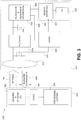
- the rectifier 314, energy storage 316, and voltage regulator 318 operate to harvest energy from received radio frequency radiation 341.
- the radio frequency radiation 341 causes radio frequency electrical signals on leads of the antenna 312.
- the rectifier 314 is connected to the antenna leads and converts the radio frequency electrical signals to a DC voltage.
- the energy storage 316 e.g ., capacitor
- Thee regulator 318 receives the filtered DC voltage and outputs both a digital supply voltage 330 to operate the hardware logic 324 and an analog supply voltage 332 to operate the sensor 320.
- the digital supply voltage 330 can be a voltage suitable for driving digital logic circuitry, such as approximately 1.2 volts, approximately 3 volts, etc. Reception of the radio frequency radiation 341 from the external reader 340 (or another source, such as ambient radiation, etc.) causes the supply voltages 330, 332 to be supplied to the sensor 320 and hardware logic 324.
- the logic 324 is configured to monitor the levels of radiant energy received via the sensor platform 320 and antenna 312 to detect changes in these levels and to determine whether the detected changes are indicative of a predetermined pattern.
- logic 324 senses the DC voltage generated at light sensor 322.
- logic 324 senses the filtered DC voltage across capacitor 316.
- the logic 324 may cause the eye-mountable device to communicate this detection to the external reader 340 so that the external reader 340 can operate an external device.
- the eye-mountable device may communicate back to the external reader 340 via backscatter radiation 343 from the antenna 312.
- the logic 324 may modulate (325) the impedance of the antenna 312 in such a way as to indicate this determination to reader 340.
- the antenna impedance and/or change in antenna impedance is detected by the external reader 340 via the backscatter signal 343.
- the external reader 340 can include an antenna front end 342 and logic 344 to decode the information indicated by the backscatter signal 343 and provide digital inputs to a processing system 346.
- the external reader 340 associates the backscatter signal 343 with a particular user gesture.
- the auxiliary device may be any device worn, carried, or otherwise positioned near the eye-mountable device 530.
- the auxiliary device is integrated within a pair of eyeglasses, a piece of jewelry such as a necklace, earing, etc. or integrated in an article of clothing worn near the head, such as a hat, headband, etc.
- the auxiliary device could be a head-mountable device.
- the inductive sensor 512 in conjunction with logic 514 is operable to detect this change in inductance and determine whether the change is indicative of a predetermined pattern.
- the logic 514 may provide digital inputs to processing system 515, which in turn may operate one or more other components (not shown) of auxiliary device 510 to wireless transmit a signal to the external reader, which in turn may operate a personal computer, tablet computer, cell phone, video game console, television, or other external device.
- the method 600 begins at block 602, in which an eye-mountable device receives a level of radiant energy.
- the eye-mountable device may receive a level of light via a light sensor or the eye-mountable device may receive a level of RF radiation from an external reader.
- the eye-mountable device may receive a level of light via a light sensor or the eye-mountable device may receive a level of RF radiation from an external reader.
- other ways to receive radiant energy are possible as well.
- the eye-mountable device determines that the detected change is indicative of a predetermined pattern of received radiant energy. For example, as described above, the eye-mountable device may determine that the radiant energy level dropped from a first level to at or below a threshold level and then returned to at or near the original first level within a threshold period of time. Accordingly, the eye-mountable device may recognize the change as being indicative of a blink. However, as also described above, other patterns are possible as well.
- the external reader receives from the wearable device, in response to transmitting the RF radiation, one or more signals that are indicative of a change in the received level of radiant energy.
- the received signals indicate levels of radiant energy received at the wearable device over a period of time.
- radiant energy may be light energy received via a light sensor on the wearable device or the radiant energy may be RF radiation previously received from the external reader.
- the signals indicate a change in the received level of radiant energy at the wearable device.
- the external reader determines that the detected change is indicative of a predetermined pattern of received radiant energy. For example, as described above, the external reader may determine that the radiant energy level dropped from a first level to at or below a threshold level and then returned to at or near the original first level within a threshold period of time. Accordingly, the eye-mountable device may recognize the change as being indicative of a blink. However, as also described above, other patterns are possible as well.
- the external reader operates one or more external devices based on the predetermined pattern.
- the external reader operates an external device by wirelessly transmitting one or more signals to a personal computer, tablet computer, cell phone, video game console, television, and/or some other computing device.
- the one or more signals may cause the external device to power on, power off, adjust volume, change a channel, change some other setting, or manipulate the external device in some other way.
- Other examples of operating an external device are possible as well.
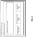
- Figure 8 depicts a computer-readable medium configured according to an example embodiment.
- the example system can include one or more processors, one or more forms of memory, one or more input devices/interfaces, one or more output devices/interfaces, and machine-readable instructions that when executed by the one or more processors cause the system to carry out the various functions, tasks, capabilities, etc., described above.
- the signal bearing medium 802 can be a communications medium 810, such as, but not limited to, a digital and/or an analog communication medium (e.g., a fiber optic cable, a waveguide, a wired communications link, a wireless communication link, etc.).
- a communications medium 810 such as, but not limited to, a digital and/or an analog communication medium (e.g., a fiber optic cable, a waveguide, a wired communications link, a wireless communication link, etc.).
- the signal bearing medium 802 can be conveyed by a wireless form of the communications medium 810.
- the one or more programming instructions 804 can be, for example, computer executable and/or logic implemented instructions.
- a computing device such as the processor-equipped external reader 180 of Figure 1 is configured to provide various operations, functions, or actions in response to the programming instructions 804 conveyed to the computing device by one or more of the computer readable medium 806, the computer recordable medium 808, and/or the communications medium 810.
- the users may be provided with an opportunity to control whether programs or features collect user information (e.g., information about a user's medical history, social network, social actions or activities, profession, a user's preferences, or a user's current location), or to control whether and/or how to receive content from the content server that may be more relevant to the user.
- user information e.g., information about a user's medical history, social network, social actions or activities, profession, a user's preferences, or a user's current location
- certain data may be treated in one or more ways before it is stored or used, so that personally identifiable information is removed.
Landscapes
- Health & Medical Sciences (AREA)
- Life Sciences & Earth Sciences (AREA)
- Engineering & Computer Science (AREA)
- Physics & Mathematics (AREA)
- Molecular Biology (AREA)
- General Health & Medical Sciences (AREA)
- Pathology (AREA)
- Biomedical Technology (AREA)
- Heart & Thoracic Surgery (AREA)
- Medical Informatics (AREA)
- Veterinary Medicine (AREA)
- Surgery (AREA)
- Animal Behavior & Ethology (AREA)
- Biophysics (AREA)
- Public Health (AREA)
- Theoretical Computer Science (AREA)
- General Engineering & Computer Science (AREA)
- Optics & Photonics (AREA)
- General Physics & Mathematics (AREA)
- Computer Networks & Wireless Communication (AREA)
- Human Computer Interaction (AREA)
- Chemical Kinetics & Catalysis (AREA)
- Chemical & Material Sciences (AREA)
- General Chemical & Material Sciences (AREA)
- Ophthalmology & Optometry (AREA)
- Emergency Medicine (AREA)
- Oral & Maxillofacial Surgery (AREA)
- Dentistry (AREA)
- Physiology (AREA)
- Arrangements For Transmission Of Measured Signals (AREA)
- Measurement Of The Respiration, Hearing Ability, Form, And Blood Characteristics Of Living Organisms (AREA)
- Eye Examination Apparatus (AREA)
Claims (15)
- System (100, 300, 500), das Folgendes umfasst:eine tragbare Vorrichtung (110, 210, 310), die eine Antenne (170, 270, 312) umfasst; undeine Lesevorrichtung (180, 340),wobei die tragbare Vorrichtung (110, 210, 310) ausgelegt ist, um:ein Ausmaß an Strahlungsenergie von der Lesevorrichtung (180, 340) zu empfangen;eine Änderung des empfangenen Ausmaßes an Strahlungsenergie zu detektieren;zu bestimmen, dass die detektierte Änderung ein vorbestimmtes Muster empfangener Strahlungsenergie anzeigt, wobei das Bestimmen, dass die detektierte Änderung des empfangenen Ausmaßes an Strahlungsenergie ein vorbestimmtes Muster empfangener Strahlungsenergie anzeigt, das Bestimmen, dass die detektierte Änderung des empfangenen Ausmaßes an Strahlungsenergie zumindest eine Körperbewegung anzeigt, umfasst; undals Reaktion auf das Bestimmen, die Antenne (170, 270, 312) zu betreiben, um einen Befehl an die Lesevorrichtung (180, 340) zu senden, der anzeigt, dass die tragbare Vorrichtung (110, 210, 310) bestimmt hat, dass die detektierte Änderung des empfangenen Ausmaßes an Strahlungsenergie ein vorbestimmtes Muster empfangener Strahlungsenergie anzeigt, undwobei die Lesevorrichtung (180, 340) ausgelegt ist, um:den Befehl von der tragbaren Vorrichtung (110, 210, 310) zu empfangen; undals Reaktion auf das Empfangen, zumindest eine externe Vorrichtung zu betreiben.
- System (100, 300, 500) nach Anspruch 1, das außerdem eine Hilfsvorrichtung (510) umfasst, die einen induktiven Sensor (512) umfasst, wobei die Hilfsvorrichtung (510) ausgelegt ist, um:ein Ausmaß an Induktivität des induktiven Sensors (512) basierend auf der Nähe der tragbaren Vorrichtung (110, 210, 310) zu der Hilfsvorrichtung (510) zu bestimmen;eine Änderung des Ausmaßes an Induktivität zu detektieren;zu bestimmen, dass die bestimmte Änderung ein vorbestimmtes Muster einer bestimmten Induktivität anzeigt; undeinen Hilfsbefehl an die Lesevorrichtung (180, 340) zu senden, der anzeigt, dass die Hilfsvorrichtung (510) bestimmt hat, dass die detektierte Änderung des Ausmaßes an Induktivität ein vorbestimmtes Muster einer bestimmten Induktivität anzeigt, undwobei die Lesevorrichtung (180, 340) außerdem ausgelegt ist, um:den Hilfsbefehl von der Hilfsvorrichtung (510) zu empfangen; undals Reaktion auf das Empfangen, zumindest eine externe Vorrichtung zu betreiben.
- System (100, 300, 500) nach Anspruch 1, wobei die tragbare Vorrichtung (110, 210, 310) ausgelegt ist, um zu bestimmen, dass die detektierte Änderung, die ein vorbestimmtes Muster empfangener Strahlungsenergie anzeigt, das Bestimmen umfasst, dass eine Kombination aus zwei oder mehr des Folgenden eingetreten ist:das empfangene Ausmaß an Strahlungsenergie hat sich innerhalb eines Schwellenzeitraums von einem ersten Ausmaß (L1) zu einem zweiten Ausmaß (L2) geändert und ist dann zu oder in die Nähe des ersten Ausmaßes (L1) zurückgekehrt,das empfangene Ausmaß an Strahlungsenergie hat sich von einem ersten Ausmaß (L1) zu einem zweiten Ausmaß (L2) geändert und ist dann über zumindest einen Schwellenzeitraum in dem zweiten Ausmaß (L2) verblieben unddas empfangene Ausmaß an Strahlungsenergie hat sich über einen Zeitraum, der länger oder gleich lang wie ein Schwellenzeitraum ist, von einem ersten Ausmaß (L1) zu einem zweiten Ausmaß (L2) geändert und ist dann zu oder in die Nähe des ersten Ausmaßes (L1) zurückgekehrt.
- Verfahren, das Folgendes umfasst:das Empfangen eines Ausmaßes an Strahlungsenergie von einer externen Lesevorrichtung (180, 340) durch eine tragbare Vorrichtung (110, 210, 310);das Detektieren einer Änderung des empfangenen Ausmaßes an Strahlungsenergie durch die tragbare Vorrichtung (110, 210, 310);das Bestimmen durch die tragbare Vorrichtung (110, 210, 310), dass die detektierte Änderung des empfangenen Ausmaßes an Strahlungsenergie ein vorbestimmtes Muster empfangener Strahlungsenergie anzeigt, wobei das Bestimmen, dass die detektierte Änderung des empfangenen Ausmaßes an Strahlungsenergie ein vorbestimmtes Muster empfangener Strahlungsenergie anzeigt, das Bestimmen umfasst, dass die detektierte Änderung des empfangenen Ausmaßes an Strahlungsenergie zumindest eine Körperbewegung anzeigt; undals Reaktion auf das Bestimmen, das Senden eines Befehls von der tragbaren Vorrichtung (110, 210, 310) an die externe Lesevorrichtung (180, 340), der anzeigt, dass die tragbare Vorrichtung (110, 210, 310) bestimmt hat, dass die detektierte Änderung des empfangenen Ausmaßes an Strahlungsenergie ein vorbestimmtes Muster empfangener Strahlungsenergie anzeigt.
- Verfahren nach Anspruch 4, wobei das Empfangen eines Ausmaßes an Strahlungsenergie Folgendes umfasst:das Empfangen eines Ausmaßes an Lichteinfall auf einen Lichtdetektor (164, 322), der der tragbaren Vorrichtung (110, 210, 310) zugeordnet ist, oderdas Empfangen eines Ausmaßes an Hochfrequenz- (HF-) Strahlung von der externen Lesevorrichtung (180, 340).
- Verfahren nach Anspruch 4, wobei das Senden eines Befehls von der tragbaren Vorrichtung (110, 210, 310) an die externe Lesevorrichtung (180, 340) die externe Lesevorrichtung (180, 340) dazu veranlasst, einen Befehl an zumindest eine externe Vorrichtung zu senden.
- Verfahren, das Folgendes umfasst:das Senden von Strahlungsenergie von einer Lesevorrichtung (180, 340) an eine tragbare Vorrichtung (110, 210, 310);als Reaktion auf das Senden, das Empfangen eines oder mehrerer Signale von der tragbaren Vorrichtung (110, 210, 310) durch die Lesevorrichtung (180, 340), die eine Änderung des von der Lesevorrichtung (180, 340) empfangenen Ausmaßes an Strahlungsenergie anzeigen;das Bestimmen, dass die Änderung des empfangenen Ausmaßes an Strahlungsenergie von der Lesevorrichtung (180, 340) ein vorbestimmtes Muster empfangener Strahlungsenergie anzeigt, durch die Lesevorrichtung (180, 340), wobei das Bestimmen, dass die Änderung des von der Lesevorrichtung (180, 340) empfangenen Ausmaßes an Strahlungsenergie ein vorbestimmtes Muster empfangener Strahlungsenergie anzeigt, das Bestimmen umfasst, dass die Änderung des von der Lesevorrichtung (180, 340) empfangenen Ausmaßes an Strahlungsenergie zumindest eine Körperbewegung anzeigt; undals Reaktion auf das Bestimmen, das Betreiben von zumindest einer externen Vorrichtung durch die Lesevorrichtung (180, 340).
- Verfahren nach Anspruch 7,
wobei das Empfangen eines oder mehrerer Signale von der tragbaren Vorrichtung (110, 210, 310) durch die Lesevorrichtung (180, 340), die eine Änderung eines von der Lesevorrichtung empfangenen Ausmaßes der Strahlungsenergie anzeigen, Folgendes umfasst:das Empfangen eines oder mehrerer Signale von der tragbaren Vorrichtung (110, 210, 310) durch die Lesevorrichtung (180, 340), die Ausmaße der Strahlungsenergie, die von der Lesevorrichtung (180, 340) an der tragbaren Vorrichtung (110, 210, 310) empfangen werden, anzeigen; undbasierend auf dem einen oder den mehreren Signalen, das Detektieren einer Änderung des Ausmaßes der Strahlungsenergie, das von der Lesevorrichtung (180, 340) an der tragbaren Vorrichtung (110, 210, 310) empfangen wird, durch die Lesevorrichtung (180, 340). - Verfahren nach Anspruch 8,
wobei die Ausmaße der Strahlungsenergie, die von der Lesevorrichtung (180, 340) an der tragbaren Vorrichtung (110, 210, 310) empfangen werden, beliebiges des Folgenden umfassen:Ausmaße von Lichteinfall auf einen Lichtdetektor (164, 322), der der tragbaren Vorrichtung (110, 210, 310) zugeordnet ist, undAusmaße von Hochfrequenz- (HF-) Strahlung, die von der Lesevorrichtung (180, 340) empfangen werden. - Verfahren nach Anspruch 7,
wobei das Empfangen eines oder mehrerer Signale von der tragbaren Vorrichtung (110, 210, 310) durch die Lesevorrichtung (180, 340), die eine Änderung des von der Lesevorrichtung (180, 340) empfangenen Ausmaßes der Strahlungsenergie anzeigen, Folgendes umfasst:das Empfangen eines Ausmaßes an Rückstrahlung von der tragbaren Vorrichtung (110, 210, 310) durch die Lesevorrichtung (180, 340); unddas Detektieren einer Änderung des empfangenen Ausmaßes an Rückstrahlung durch die Lesevorrichtung (180, 340). - Verfahren nach Anspruch 4 oder 7, wobei die zumindest eine Körperbewegung ein Blinzeln, ein Nicken oder eine Änderung der Blickrichtung umfasst.
- Verfahren nach Anspruch 11, wobei die zumindest eine Körperbewegung ein Blinzeln umfasst, und wobei das Bestimmen, dass die Änderung des empfangenen Ausmaßes an Strahlungsenergie ein Blinzeln anzeigt, Folgendes umfasst:
das Bestimmen, dass sich das empfangene Ausmaß an Strahlungsenergie innerhalb eines Schwellenzeitraums von einem ersten Ausmaß (L1) zu einem zweiten Ausmaß (L2) geändert hat und dann zu oder in die Nähe des ersten Ausmaßes (L1) zurückgekehrt ist. - Verfahren nach Anspruch 11, wobei die zumindest eine Körperbewegung eine Änderung der Blickrichtung umfasst, und wobei das Bestimmen, dass die Änderung des empfangenen Ausmaßes an Strahlungsenergie eine Änderung der Blickrichtung anzeigt, Folgendes umfasst:
das Bestimmen, dass sich das empfangene Ausmaß an Strahlungsenergie von einem ersten Ausmaß (L1) zu einem zweiten Ausmaß (L2) geändert hat und dann über zumindest einen Schwellenzeitraum in dem zweiten Ausmaß (L2) verblieben ist. - Verfahren nach Anspruch 11, wobei die zumindest eine Körperbewegung ein Nicken umfasst, und wobei das Bestimmen, dass die Änderung des empfangenen Ausmaßes an Strahlungsenergie ein Nicken anzeigt, Folgendes umfasst:
das Bestimmen, dass sich das empfangene Ausmaß an Strahlungsenergie über einen Zeitraum, der länger oder gleich lang wie ein Schwellenzeitraum ist, von einem ersten Ausmaß (L1) zu einem zweiten Ausmaß (L2) geändert hat und dann zu oder in die Nähe des ersten Ausmaßes (L1) zurückgekehrt ist. - Verfahren nach Anspruch 4 oder 7, wobei das Bestimmen, dass die Änderung des empfangenen Ausmaßes an Strahlungsenergie ein vorbestimmtes Muster empfangener Strahlungsenergie anzeigt, das Bestimmen umfasst, dass eine Kombination aus zwei oder mehr des Folgenden eingetreten ist:das empfangene Ausmaß an Strahlungsenergie hat sich innerhalb eines Schwellenzeitraums von einem ersten Ausmaß (L1) zu einem zweiten Ausmaß (L2) geändert und ist dann zu oder in die Nähe des ersten Ausmaßes (L1) zurückgekehrt,das empfangene Ausmaß an Strahlungsenergie hat sich von einem ersten Ausmaß (L1) zu einem zweiten Ausmaß (L2) geändert und ist dann über zumindest einen Schwellenzeitraum in dem zweiten Ausmaß (L2) verblieben unddas empfangene Ausmaß an Strahlungsenergie hat sich über einen Zeitraum, der länger oder gleich lang wie ein Schwellenzeitraum ist, von einem ersten Ausmaß (L1) zu einem zweiten Ausmaß (L2) geändert und ist dann zu oder in die Nähe des ersten Ausmaßes (L1) zurückgekehrt.
Applications Claiming Priority (2)
| Application Number | Priority Date | Filing Date | Title |
|---|---|---|---|
| US14/143,070 US9808157B2 (en) | 2013-12-30 | 2013-12-30 | Hands-free interface |
| PCT/US2014/061115 WO2015102728A1 (en) | 2013-12-30 | 2014-10-17 | Hands-free interface |
Publications (3)
| Publication Number | Publication Date |
|---|---|
| EP3090316A1 EP3090316A1 (de) | 2016-11-09 |
| EP3090316A4 EP3090316A4 (de) | 2017-09-06 |
| EP3090316B1 true EP3090316B1 (de) | 2021-04-07 |
Family
ID=53480459
Family Applications (1)
| Application Number | Title | Priority Date | Filing Date |
|---|---|---|---|
| EP14877390.6A Active EP3090316B1 (de) | 2013-12-30 | 2014-10-17 | Freihändige schnittstelle |
Country Status (3)
| Country | Link |
|---|---|
| US (1) | US9808157B2 (de) |
| EP (1) | EP3090316B1 (de) |
| WO (1) | WO2015102728A1 (de) |
Families Citing this family (6)
| Publication number | Priority date | Publication date | Assignee | Title |
|---|---|---|---|---|
| US9696564B1 (en) | 2012-08-21 | 2017-07-04 | Verily Life Sciences Llc | Contact lens with metal portion and polymer layer having indentations |
| US10262462B2 (en) | 2014-04-18 | 2019-04-16 | Magic Leap, Inc. | Systems and methods for augmented and virtual reality |
| US9933634B2 (en) | 2014-06-13 | 2018-04-03 | Verily Life Sciences Llc | Apparatus, system and method for gaze tracking based on photodetection by an eye-mountable device |
| EP3289430B1 (de) * | 2015-04-27 | 2019-10-23 | Snap-Aid Patents Ltd. | Schätzung und verwendung einer relativen kopfhaltung und kamerasichtfeld |
| US9772510B2 (en) * | 2015-09-01 | 2017-09-26 | Verily Life Sciences Llc | Apparatus, system and method for photodetection with a transimpedance amplifier of an eye-mountable device |
| US11700999B2 (en) * | 2018-12-20 | 2023-07-18 | Verily Life Sciences Llc | Ambient brightness-based power savings for ophthalmic device |
Family Cites Families (12)
| Publication number | Priority date | Publication date | Assignee | Title |
|---|---|---|---|---|
| GB2222505B (en) * | 1988-09-02 | 1993-06-16 | Plessey Co Plc | A method of establishing a radio link in one of a plurality of channels between two radio units |
| USRE39539E1 (en) * | 1996-08-19 | 2007-04-03 | Torch William C | System and method for monitoring eye movement |
| US6885818B2 (en) | 2001-07-30 | 2005-04-26 | Hewlett-Packard Development Company, L.P. | System and method for controlling electronic devices |
| AR045370A1 (es) | 2003-08-15 | 2005-10-26 | E Vision Llc | Sistema de lente electro-activo |
| EP1760515A3 (de) | 2003-10-03 | 2011-08-31 | Invisia Ltd. | Mehrstärkenlinse zur Korrekur von Fehlsichtigkeit |
| US8608310B2 (en) | 2007-11-07 | 2013-12-17 | University Of Washington Through Its Center For Commercialization | Wireless powered contact lens with biosensor |
| AU2012238954A1 (en) | 2011-04-07 | 2013-11-21 | Sensimed Sa | Device and method for detecting ophtalmic and/or brain diseases |
| US8632182B2 (en) | 2011-05-05 | 2014-01-21 | Sony Computer Entertainment Inc. | Interface using eye tracking contact lenses |
| US8721074B2 (en) | 2011-11-30 | 2014-05-13 | Johnson & Johnson Vision Care, Inc. | Electrical interconnects in an electronic contact lens |
| US8988349B2 (en) | 2012-02-28 | 2015-03-24 | Google Technology Holdings LLC | Methods and apparatuses for operating a display in an electronic device |
| US9128522B2 (en) | 2012-04-02 | 2015-09-08 | Google Inc. | Wink gesture input for a head-mountable device |
| US9072465B2 (en) | 2012-04-03 | 2015-07-07 | Johnson & Johnson Vision Care, Inc. | Blink detection system for electronic ophthalmic lens |
-
2013
- 2013-12-30 US US14/143,070 patent/US9808157B2/en active Active
-
2014
- 2014-10-17 WO PCT/US2014/061115 patent/WO2015102728A1/en not_active Ceased
- 2014-10-17 EP EP14877390.6A patent/EP3090316B1/de active Active
Non-Patent Citations (1)
| Title |
|---|
| None * |
Also Published As
| Publication number | Publication date |
|---|---|
| EP3090316A1 (de) | 2016-11-09 |
| US9808157B2 (en) | 2017-11-07 |
| EP3090316A4 (de) | 2017-09-06 |
| US20150182116A1 (en) | 2015-07-02 |
| WO2015102728A1 (en) | 2015-07-09 |
Similar Documents
| Publication | Publication Date | Title |
|---|---|---|
| JP6764958B2 (ja) | 条件検索 | |
| AU2018204407B2 (en) | Device with dual power sources | |
| US8833934B1 (en) | Devices and methods for a contact lens with an outward facing light source | |
| US10448894B2 (en) | Conditional storage | |
| EP3413784B1 (de) | Geschlossene-augen-schnittstelle | |
| US9954223B2 (en) | Fabrication methods for batteries | |
| EP3090316B1 (de) | Freihändige schnittstelle | |
| US9962115B2 (en) | Eye-mountable devices and structures for eye-mountable devices |
Legal Events
| Date | Code | Title | Description |
|---|---|---|---|
| PUAI | Public reference made under article 153(3) epc to a published international application that has entered the european phase |
Free format text: ORIGINAL CODE: 0009012 |
|
| 17P | Request for examination filed |
Effective date: 20160628 |
|
| AK | Designated contracting states |
Kind code of ref document: A1 Designated state(s): AL AT BE BG CH CY CZ DE DK EE ES FI FR GB GR HR HU IE IS IT LI LT LU LV MC MK MT NL NO PL PT RO RS SE SI SK SM TR |
|
| AX | Request for extension of the european patent |
Extension state: BA ME |
|
| DAX | Request for extension of the european patent (deleted) | ||
| REG | Reference to a national code |
Ref country code: DE Ref legal event code: R079 Ref document number: 602014076468 Country of ref document: DE Free format text: PREVIOUS MAIN CLASS: G06F0001160000 Ipc: A61B0005000000 |
|
| A4 | Supplementary search report drawn up and despatched |
Effective date: 20170803 |
|
| RIC1 | Information provided on ipc code assigned before grant |
Ipc: A61B 5/11 20060101ALI20170728BHEP Ipc: A61B 5/1468 20060101ALI20170728BHEP Ipc: A61B 5/00 20060101AFI20170728BHEP Ipc: G06F 3/01 20060101ALI20170728BHEP Ipc: A61B 5/145 20060101ALI20170728BHEP |
|
| STAA | Information on the status of an ep patent application or granted ep patent |
Free format text: STATUS: EXAMINATION IS IN PROGRESS |
|
| 17Q | First examination report despatched |
Effective date: 20190225 |
|
| GRAP | Despatch of communication of intention to grant a patent |
Free format text: ORIGINAL CODE: EPIDOSNIGR1 |
|
| STAA | Information on the status of an ep patent application or granted ep patent |
Free format text: STATUS: GRANT OF PATENT IS INTENDED |
|
| INTG | Intention to grant announced |
Effective date: 20201022 |
|
| GRAS | Grant fee paid |
Free format text: ORIGINAL CODE: EPIDOSNIGR3 |
|
| GRAA | (expected) grant |
Free format text: ORIGINAL CODE: 0009210 |
|
| STAA | Information on the status of an ep patent application or granted ep patent |
Free format text: STATUS: THE PATENT HAS BEEN GRANTED |
|
| AK | Designated contracting states |
Kind code of ref document: B1 Designated state(s): AL AT BE BG CH CY CZ DE DK EE ES FI FR GB GR HR HU IE IS IT LI LT LU LV MC MK MT NL NO PL PT RO RS SE SI SK SM TR |
|
| REG | Reference to a national code |
Ref country code: GB Ref legal event code: FG4D |
|
| REG | Reference to a national code |
Ref country code: AT Ref legal event code: REF Ref document number: 1378610 Country of ref document: AT Kind code of ref document: T Effective date: 20210415 Ref country code: CH Ref legal event code: EP |
|
| REG | Reference to a national code |
Ref country code: DE Ref legal event code: R096 Ref document number: 602014076468 Country of ref document: DE |
|
| REG | Reference to a national code |
Ref country code: IE Ref legal event code: FG4D |
|
| REG | Reference to a national code |
Ref country code: LT Ref legal event code: MG9D |
|
| REG | Reference to a national code |
Ref country code: NL Ref legal event code: MP Effective date: 20210407 Ref country code: AT Ref legal event code: MK05 Ref document number: 1378610 Country of ref document: AT Kind code of ref document: T Effective date: 20210407 |
|
| PG25 | Lapsed in a contracting state [announced via postgrant information from national office to epo] |
Ref country code: HR Free format text: LAPSE BECAUSE OF FAILURE TO SUBMIT A TRANSLATION OF THE DESCRIPTION OR TO PAY THE FEE WITHIN THE PRESCRIBED TIME-LIMIT Effective date: 20210407 Ref country code: LT Free format text: LAPSE BECAUSE OF FAILURE TO SUBMIT A TRANSLATION OF THE DESCRIPTION OR TO PAY THE FEE WITHIN THE PRESCRIBED TIME-LIMIT Effective date: 20210407 Ref country code: NL Free format text: LAPSE BECAUSE OF FAILURE TO SUBMIT A TRANSLATION OF THE DESCRIPTION OR TO PAY THE FEE WITHIN THE PRESCRIBED TIME-LIMIT Effective date: 20210407 Ref country code: FI Free format text: LAPSE BECAUSE OF FAILURE TO SUBMIT A TRANSLATION OF THE DESCRIPTION OR TO PAY THE FEE WITHIN THE PRESCRIBED TIME-LIMIT Effective date: 20210407 Ref country code: AT Free format text: LAPSE BECAUSE OF FAILURE TO SUBMIT A TRANSLATION OF THE DESCRIPTION OR TO PAY THE FEE WITHIN THE PRESCRIBED TIME-LIMIT Effective date: 20210407 Ref country code: BG Free format text: LAPSE BECAUSE OF FAILURE TO SUBMIT A TRANSLATION OF THE DESCRIPTION OR TO PAY THE FEE WITHIN THE PRESCRIBED TIME-LIMIT Effective date: 20210707 |
|
| PG25 | Lapsed in a contracting state [announced via postgrant information from national office to epo] |
Ref country code: IS Free format text: LAPSE BECAUSE OF FAILURE TO SUBMIT A TRANSLATION OF THE DESCRIPTION OR TO PAY THE FEE WITHIN THE PRESCRIBED TIME-LIMIT Effective date: 20210807 Ref country code: GR Free format text: LAPSE BECAUSE OF FAILURE TO SUBMIT A TRANSLATION OF THE DESCRIPTION OR TO PAY THE FEE WITHIN THE PRESCRIBED TIME-LIMIT Effective date: 20210708 Ref country code: LV Free format text: LAPSE BECAUSE OF FAILURE TO SUBMIT A TRANSLATION OF THE DESCRIPTION OR TO PAY THE FEE WITHIN THE PRESCRIBED TIME-LIMIT Effective date: 20210407 Ref country code: PL Free format text: LAPSE BECAUSE OF FAILURE TO SUBMIT A TRANSLATION OF THE DESCRIPTION OR TO PAY THE FEE WITHIN THE PRESCRIBED TIME-LIMIT Effective date: 20210407 Ref country code: PT Free format text: LAPSE BECAUSE OF FAILURE TO SUBMIT A TRANSLATION OF THE DESCRIPTION OR TO PAY THE FEE WITHIN THE PRESCRIBED TIME-LIMIT Effective date: 20210809 Ref country code: NO Free format text: LAPSE BECAUSE OF FAILURE TO SUBMIT A TRANSLATION OF THE DESCRIPTION OR TO PAY THE FEE WITHIN THE PRESCRIBED TIME-LIMIT Effective date: 20210707 Ref country code: ES Free format text: LAPSE BECAUSE OF FAILURE TO SUBMIT A TRANSLATION OF THE DESCRIPTION OR TO PAY THE FEE WITHIN THE PRESCRIBED TIME-LIMIT Effective date: 20210407 Ref country code: RS Free format text: LAPSE BECAUSE OF FAILURE TO SUBMIT A TRANSLATION OF THE DESCRIPTION OR TO PAY THE FEE WITHIN THE PRESCRIBED TIME-LIMIT Effective date: 20210407 Ref country code: SE Free format text: LAPSE BECAUSE OF FAILURE TO SUBMIT A TRANSLATION OF THE DESCRIPTION OR TO PAY THE FEE WITHIN THE PRESCRIBED TIME-LIMIT Effective date: 20210407 |
|
| REG | Reference to a national code |
Ref country code: DE Ref legal event code: R097 Ref document number: 602014076468 Country of ref document: DE |
|
| PG25 | Lapsed in a contracting state [announced via postgrant information from national office to epo] |
Ref country code: RO Free format text: LAPSE BECAUSE OF FAILURE TO SUBMIT A TRANSLATION OF THE DESCRIPTION OR TO PAY THE FEE WITHIN THE PRESCRIBED TIME-LIMIT Effective date: 20210407 Ref country code: SK Free format text: LAPSE BECAUSE OF FAILURE TO SUBMIT A TRANSLATION OF THE DESCRIPTION OR TO PAY THE FEE WITHIN THE PRESCRIBED TIME-LIMIT Effective date: 20210407 Ref country code: SM Free format text: LAPSE BECAUSE OF FAILURE TO SUBMIT A TRANSLATION OF THE DESCRIPTION OR TO PAY THE FEE WITHIN THE PRESCRIBED TIME-LIMIT Effective date: 20210407 Ref country code: EE Free format text: LAPSE BECAUSE OF FAILURE TO SUBMIT A TRANSLATION OF THE DESCRIPTION OR TO PAY THE FEE WITHIN THE PRESCRIBED TIME-LIMIT Effective date: 20210407 Ref country code: CZ Free format text: LAPSE BECAUSE OF FAILURE TO SUBMIT A TRANSLATION OF THE DESCRIPTION OR TO PAY THE FEE WITHIN THE PRESCRIBED TIME-LIMIT Effective date: 20210407 Ref country code: DK Free format text: LAPSE BECAUSE OF FAILURE TO SUBMIT A TRANSLATION OF THE DESCRIPTION OR TO PAY THE FEE WITHIN THE PRESCRIBED TIME-LIMIT Effective date: 20210407 |
|
| PLBE | No opposition filed within time limit |
Free format text: ORIGINAL CODE: 0009261 |
|
| STAA | Information on the status of an ep patent application or granted ep patent |
Free format text: STATUS: NO OPPOSITION FILED WITHIN TIME LIMIT |
|
| 26N | No opposition filed |
Effective date: 20220110 |
|
| REG | Reference to a national code |
Ref country code: CH Ref legal event code: PL |
|
| PG25 | Lapsed in a contracting state [announced via postgrant information from national office to epo] |
Ref country code: IS Free format text: LAPSE BECAUSE OF FAILURE TO SUBMIT A TRANSLATION OF THE DESCRIPTION OR TO PAY THE FEE WITHIN THE PRESCRIBED TIME-LIMIT Effective date: 20210807 Ref country code: AL Free format text: LAPSE BECAUSE OF FAILURE TO SUBMIT A TRANSLATION OF THE DESCRIPTION OR TO PAY THE FEE WITHIN THE PRESCRIBED TIME-LIMIT Effective date: 20210407 |
|
| REG | Reference to a national code |
Ref country code: BE Ref legal event code: MM Effective date: 20211031 |
|
| PG25 | Lapsed in a contracting state [announced via postgrant information from national office to epo] |
Ref country code: MC Free format text: LAPSE BECAUSE OF FAILURE TO SUBMIT A TRANSLATION OF THE DESCRIPTION OR TO PAY THE FEE WITHIN THE PRESCRIBED TIME-LIMIT Effective date: 20210407 |
|
| PG25 | Lapsed in a contracting state [announced via postgrant information from national office to epo] |
Ref country code: LU Free format text: LAPSE BECAUSE OF NON-PAYMENT OF DUE FEES Effective date: 20211017 Ref country code: IT Free format text: LAPSE BECAUSE OF FAILURE TO SUBMIT A TRANSLATION OF THE DESCRIPTION OR TO PAY THE FEE WITHIN THE PRESCRIBED TIME-LIMIT Effective date: 20210407 Ref country code: BE Free format text: LAPSE BECAUSE OF NON-PAYMENT OF DUE FEES Effective date: 20211031 |
|
| PG25 | Lapsed in a contracting state [announced via postgrant information from national office to epo] |
Ref country code: LI Free format text: LAPSE BECAUSE OF NON-PAYMENT OF DUE FEES Effective date: 20211031 Ref country code: CH Free format text: LAPSE BECAUSE OF NON-PAYMENT OF DUE FEES Effective date: 20211031 |
|
| PG25 | Lapsed in a contracting state [announced via postgrant information from national office to epo] |
Ref country code: FR Free format text: LAPSE BECAUSE OF NON-PAYMENT OF DUE FEES Effective date: 20211031 |
|
| PG25 | Lapsed in a contracting state [announced via postgrant information from national office to epo] |
Ref country code: IE Free format text: LAPSE BECAUSE OF NON-PAYMENT OF DUE FEES Effective date: 20211017 |
|
| PG25 | Lapsed in a contracting state [announced via postgrant information from national office to epo] |
Ref country code: HU Free format text: LAPSE BECAUSE OF FAILURE TO SUBMIT A TRANSLATION OF THE DESCRIPTION OR TO PAY THE FEE WITHIN THE PRESCRIBED TIME-LIMIT; INVALID AB INITIO Effective date: 20141017 |
|
| P01 | Opt-out of the competence of the unified patent court (upc) registered |
Effective date: 20230522 |
|
| PG25 | Lapsed in a contracting state [announced via postgrant information from national office to epo] |
Ref country code: CY Free format text: LAPSE BECAUSE OF FAILURE TO SUBMIT A TRANSLATION OF THE DESCRIPTION OR TO PAY THE FEE WITHIN THE PRESCRIBED TIME-LIMIT Effective date: 20210407 |
|
| PG25 | Lapsed in a contracting state [announced via postgrant information from national office to epo] |
Ref country code: MK Free format text: LAPSE BECAUSE OF FAILURE TO SUBMIT A TRANSLATION OF THE DESCRIPTION OR TO PAY THE FEE WITHIN THE PRESCRIBED TIME-LIMIT Effective date: 20210407 |
|
| PG25 | Lapsed in a contracting state [announced via postgrant information from national office to epo] |
Ref country code: MT Free format text: LAPSE BECAUSE OF FAILURE TO SUBMIT A TRANSLATION OF THE DESCRIPTION OR TO PAY THE FEE WITHIN THE PRESCRIBED TIME-LIMIT Effective date: 20210407 |
|
| PG25 | Lapsed in a contracting state [announced via postgrant information from national office to epo] |
Ref country code: TR Free format text: LAPSE BECAUSE OF FAILURE TO SUBMIT A TRANSLATION OF THE DESCRIPTION OR TO PAY THE FEE WITHIN THE PRESCRIBED TIME-LIMIT Effective date: 20210407 |
|
| PGFP | Annual fee paid to national office [announced via postgrant information from national office to epo] |
Ref country code: DE Payment date: 20251028 Year of fee payment: 12 |
|
| PGFP | Annual fee paid to national office [announced via postgrant information from national office to epo] |
Ref country code: GB Payment date: 20251023 Year of fee payment: 12 |