EP3090440B1 - Vorrichtung und verfahren zum pulsen von linsen - Google Patents
Vorrichtung und verfahren zum pulsen von linsen Download PDFInfo
- Publication number
- EP3090440B1 EP3090440B1 EP14876632.2A EP14876632A EP3090440B1 EP 3090440 B1 EP3090440 B1 EP 3090440B1 EP 14876632 A EP14876632 A EP 14876632A EP 3090440 B1 EP3090440 B1 EP 3090440B1
- Authority
- EP
- European Patent Office
- Prior art keywords
- lens
- ions
- pressure
- mass spectrometer
- region
- Prior art date
- Legal status (The legal status is an assumption and is not a legal conclusion. Google has not performed a legal analysis and makes no representation as to the accuracy of the status listed.)
- Active
Links
Images


Classifications
-
- H—ELECTRICITY
- H01—ELECTRIC ELEMENTS
- H01J—ELECTRIC DISCHARGE TUBES OR DISCHARGE LAMPS
- H01J49/00—Particle spectrometers or separator tubes
- H01J49/02—Details
- H01J49/06—Electron- or ion-optical arrangements
- H01J49/067—Ion lenses, apertures, skimmers
-
- H—ELECTRICITY
- H01—ELECTRIC ELEMENTS
- H01J—ELECTRIC DISCHARGE TUBES OR DISCHARGE LAMPS
- H01J49/00—Particle spectrometers or separator tubes
- H01J49/02—Details
- H01J49/06—Electron- or ion-optical arrangements
- H01J49/061—Ion deflecting means, e.g. ion gates
-
- H—ELECTRICITY
- H01—ELECTRIC ELEMENTS
- H01J—ELECTRIC DISCHARGE TUBES OR DISCHARGE LAMPS
- H01J49/00—Particle spectrometers or separator tubes
- H01J49/02—Details
- H01J49/06—Electron- or ion-optical arrangements
- H01J49/062—Ion guides
-
- H—ELECTRICITY
- H01—ELECTRIC ELEMENTS
- H01J—ELECTRIC DISCHARGE TUBES OR DISCHARGE LAMPS
- H01J49/00—Particle spectrometers or separator tubes
- H01J49/26—Mass spectrometers or separator tubes
- H01J49/34—Dynamic spectrometers
- H01J49/40—Time-of-flight spectrometers
Definitions
- the teachings described herein relate to lens pulsing in mass spectrometry analysis.
- Transporting of ions through stages in mass spectrometers is commonly performed using several interfacing apparatus.
- gating mechanisms can be utilized to control the flow of ions between the various stages.
- a skimmer cone consisting of a large cone shaped disc that contains a small hole or aperture at the centre is used to select ions that may be radially separated. Generally ions from the central portion of an ion beam are selected for transmission with the remaining ions being removed.
- the pulsing of the skimmer voltage can be utilized to introduce an artificial duty cycle to cause modulation of an ion beam which can reduce the total ion current in exceptionally bright beams.
- Such pulsing consists of switching the voltage of the skimmer between two voltages, one in which ions can pass through the skimmer and one in which the ions cannot.
- the phenomenon of skimmer pulsing is mass dependent and has also exhibited surprisingly non-linear behavior in some cases.
- linearity of an ion signal seen when pulsing a single gating lens over a wide duty cycle range is not very good at lower duty cycles. This affects fill time linearity on the quardupole trapping instruments and ITC (Total ion current) linearity on Time-of-Flight mass spectrometer instruments.
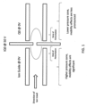
- FIG. 1 The normal situation is conceptually represented in Figure 1 .
- the stopping potential is applied to the gating lens (labeled IQ0)
- a zone is created (zone of perturbation) on both sides of the lens where ions therein have their trajectories spoiled such that they are deflected away from a stable trajectory and are either ejected or contact one of the rods and will therefore not pass on to the next section of the analyzer.
- the field created on the high pressure side left side causes the ions with high mobility to deviate from an acceptable to an unacceptable trajectory preferentially relative to low mobility ions.
- US 2004/108455 A1 discloses a time of flight ion trap tandem mass spectrometer system.
- US 5,739,530 discloses a method and device for the introduction of ions into quadrupole ion traps.
- US 5,572,022 discloses a method and apparatus of increasing dynamic range and sensitivity of a mass spectrometer.
- US 2002/175278 A1 discloses an atmospheric and vacuum pressure MALDI ion source.
- ions downstream of the gating lens on the lower pressure side of the lens will experience the field created when the dual lens is energized. Since the ion mobility properties scale with pressure, lower mobility effects will exist in these lower pressure environments.
- the within describe teachings provide a lens providing two functions.
- the lens separates a high pressure zone where mobility effects dominate from a low pressure zone where electrostatic effects dominate and the lens also can effectively modulate ions.
- the dual lens IQ0 ion optic produces good linearity even for low duty cycles.
- improved fill linearity for ion traps and potentially higher score in identification of compounds in triple-TOF instruments as a result of improved ITC linearity is expected.
- a method for transmitting ions in a mass spectrometer from a region of higher pressure to a region of lower pressure comprising passing the ions through a gating apparatus disposed between said higher pressure region and said lower pressure region, wherein the region of higher pressure is in an ion guide at atmospheric pressure
- the gating apparatus comprising: first and second electrostatic lenses, each of said electrostatic lenses being operably controlled by one or more controllers capable of maintaining different voltages on each of said lenses; wherein the first electrostatic lens is disposed adjacent to the region of higher pressure and operates in a continuous mode having a voltage that is fixed at a predetermined value so that ions are not caused by a modulation field to deviate to an unstable trajectory in the high pressure region and so as to allow traversal of ions through the first lens, and wherein the second electrostatic lens is disposed adjacent to the region of lower pressure and is situated downstream from said first lens, said second electrostatic lens having a voltage that varies between at least two different voltages wherein,
- a mass spectrometer device comprising: an ion guide operating at a first pressure, wherein said first pressure is atmospheric pressure; an ion trap or Time-of-Flight, TOF, mass spectrometer operating at a second pressure that is lower than the first pressure; a gating apparatus disposed between said ion guide and said ion trap or TOF mass spectrometer for transmitting ions from said ion guide to said ion trap or TOF mass spectrometer, said gating apparatus comprising a first electrostatic lens and a second electrostatic lens, the first lens being situated adjacent to the ion guide and the second lens being adjacent to said ion trap or TOF mass spectrometer; at least one controller for operably controlling the voltages on each of the first and second lens separately, wherein the controller is configured to maintain the first electrostatic lens in a continuous operating mode at a fixed, predetermined voltage so that ions are not caused by a modulation field to deviate to an unstable trajectory
- a third electrostatic lens is disposed downstream from the second lens and operates at a predetermined value that allows traversal of ions through the third lens.
- the region of lower pressure is in a Q0 stage of a tandem mass spectrometer.
- the region of lower pressure is in a quadrupole ion trap.
- the region of lower pressure is in a TOF mass spectrometer.
- the gating apparatus comprises a third lens disposed downstream from said second lens.
- the voltages on said third and first lenses are the same.
- the gating effects used with respect to the present invention are used to primarily avoid oversaturation of the detector with bright ion beams
- the use in an ion trap can be used to simulate faster speeds by reducing fill times to a fraction of the normal fill times (For example, reducing fill times from 2 ms, down to 0.05 ms). Such benefits reduce space-charge effects.
- FIG. 1 show the layout of a conventional gating mechanism that operates between an ion guide and the first stage of a tandem mass spectrometer, referred to commonly in the art as Q0.
- ions from an ion source travel from left to right in the figure. Ions are transported in a quadrupole type ion guide at atmospheric pressure that is operating at 0V.
- the Q0 stage of the tandem mass spectrometer operates also at 0V and is under reduced pressure.
- Situated between the ion guide and the Q0 stage is a single modulating gating electrode. On the upstream side of the gating electrode (left side), there exists a high pressure region and on the other side of the gating electrode there is a low pressure region.
- the modulating gating electrode switches between two voltages, a first voltage that prevents ions from passing through the gating electrode (50V) and a second voltage (0V) that allows ions to pass through the electrode from the ion guide to Q0. While these two potentials have been specifically described, it would be appreciated that other voltages could also be utilized to achieve the same effect depending on the potentials applied to the ion guide and Q0 quadrupoles. As would be appreciated, various controller and power supplies are electrical connections are required so to provide and control the voltages being applied to the gates, ion guide, tandem mass spectrometer and/or other devices that are utilized.
- FIG. 2 shows the layout of an embodiment of a gating mechanism in accordance with the present teachings.
- the gating mechanism operates between an ion guide and the first stage of a tandem mass spectrometer, referred to commonly in the art as Q0 as described previously in FIG. 1 with the exception that the single modulating electrode is replaced with an assembly containing two electrode lenses.
- the first electrode lens which operates on the high pressure side of the assembly and in FIG.2 is adjacent to the ion guide at 0V operates at a fixed potential of 0V.
- This first lens operates continuously at this fixed potential.
- the potential is chosen so as to allow ions to pass through the first lens.
- the potential of this first upstream lens operates at the same voltage as the ion guide preceding it.
- the second lens directly downstream for the first lens operates in a similar fashion to the modulating gate found in FIG. 1 .
- the second lens operates at one of at least two voltages wherein in the first voltage, the gate prevents traversal of ions through itself (50V) and when operated at the second voltage, the gate allows traversal of ions through itself (0V).
- the potential of this second voltage operates at the same voltage as the ion guide and first lens preceding it.
- the first lens is electrically separated from the second lens so the voltage supplied to one of the lenses is not transmitted to the other.
- the lenses can be separated by a fixed distance or alternatively an insulating material can be inserted between the two lenses to achieve the same effect.
- the first lens operating in a continuous mode at a fixed potential minimizes the modulation field that would normally be present on either side of the second lens from affecting ions on the high pressure zone in the zone of perturbation where ion mobility effects would normally affect the distribution of ions as they approach the ion gate. While a zone of perturbation still exists on the lower pressure side of the gate, the reduced amount of gas present also reduces any ion mobility effects that might be present. While specific voltages are shown, as would be appreciated, any voltages could be used so long as the functionality of the lens is not impeded.
- FIG. 3 shows the layout of another embodiment of the present invention similar to the embodiment described in FIG. 2 , but the assembly contains a third lens electrode positioned downstream from the second lens electrode referred to above.
- the third electrode operates in a similar fashion to the first electrode and has a fixed voltage that allows traversal of ions through it. Due to the reduced pressure on the lower pressure side of the gate, this third electrode is not required as ion mobility effects as a result of a modulating electric field may be small or non existent in any event. In preferred embodiments, this third electrode operates at the same potential as the first electrode.
- FIG. 4 shows the linearity of plots of intensity as a function of the modulation for various ion masses.
- the ions were generated from the fragmentation of peptides, all using the same voltage and the data was acquired all at the same time.
- the x-axis for each of these plots provides the percentage of time in which the second lens operates at a voltage in which ions are allowed to pass through the gate as a percentage of total time.
- the coefficient of determination (R 2 ) for each of these plots is around 0.99 indicating a very high degree of linearity in the plots visualized. Any slight deviations in linearity were primarily in plots having high intensity counts that were likely a result of saturation effects on the detectors.
Landscapes
- Chemical & Material Sciences (AREA)
- Analytical Chemistry (AREA)
- Electron Tubes For Measurement (AREA)
- Other Investigation Or Analysis Of Materials By Electrical Means (AREA)
Claims (9)
- Verfahren zum Übertragen von Ionen in einem Massenspektrometer von einem Bereich höheren Drucks zu einem Bereich niedrigeren Drucks, umfassend ein Leiten der Ionen durch ein Schleusengerät, das zwischen dem Bereich höheren Drucks und dem Bereich niedrigeren Drucks angeordnet ist, wobei der Bereich höheren Drucks in einer Ionenführung bei Atmosphärendruck ist, das Schleusengerät umfassend:eine erste und eine zweite elektrostatische Linse, wobei jede der elektrostatischen Linsen gesteuert von einer oder mehreren Steuerungen funktionsfähig ist, die in der Lage sind, unterschiedliche Spannungen an jeder der Linsen aufrechtzuerhalten;wobei die erste elektrostatische Linse angrenzend an den Bereich höheren Drucks angeordnet ist und in einem kontinuierlichen Modus mit einer Spannung betrieben wird, die auf einen vorbestimmten Wert festgelegt ist, um einen Durchgang von Ionen durch die erste Linse zu ermöglichen, undwobei die zweite elektrostatische Linse angrenzend an den Bereich niedrigeren Drucks und stromabwärts von der ersten Linse angeordnet ist, wobei die zweite elektrostatische Linse eine Spannung aufweist, die zwischen mindestens zwei verschiedenen Spannungen variiert, wobei die Ionen bei einer ersten Spannung die zweite Linse durchqueren können und die Ionen bei einer zweiten Spannung daran gehindert sind, die zweite elektrostatische Linse zu durchqueren.
- Verfahren nach Anspruch 1, wobei eine dritte elektrostatische Linse stromabwärts von der zweiten Linse angeordnet ist und mit einem vorbestimmten Wert betrieben wird, der einen Durchgang von Ionen durch die dritte Linse ermöglicht.
- Verfahren nach Anspruch 2, wobei die Spannungen an der ersten und der dritten Linse gleich sind.
- Verfahren nach Anspruch 1, wobei der Bereich niedrigeren Drucks in einer ersten Stufe eines Tandem-Massenspektrometers ist.
- Verfahren nach Anspruch 1, wobei der Bereich niedrigeren Drucks in einer Quadrupol-Ionenfalle ist.
- Verfahren nach Anspruch 1, wobei der Bereich niedrigeren Drucks in einem TOF-Massenspektrometer ist.
- Massenspektrometervorrichtung, umfassend:einen Ionenleiter, der bei einem ersten Druck betrieben wird, wobei der erste Druck Atmosphärendruck ist;eine Ionenfalle oder ein Massenspektrometer für Flugzeit, TOF, das bei einem zweiten Druck betrieben wird, der niedriger ist als der erste Druck;ein Schleusengerät, das zwischen dem Ionenleiter und der Ionenfalle oder dem TOF-Massenspektrometer angeordnet ist, um Ionen von dem Ionenleiter zu der Ionenfalle oder dem TOF-Massenspektrometer zu übertragen, wobei das Schleusengerät eine erste elektrostatische Linse und eine zweite elektrostatische Linse umfasst, wobei sich die erste Linse angrenzend an den Ionenleiter befindet und die zweite Linse angrenzend an die Ionenfalle oder den TOF-Massenspektrometer ist;mindestens eine Steuerung zum separaten Steuern der Spannungen an jeder von der ersten und der zweiten Linse, wobei die Steuerung konfiguriert ist, um die erste elektrostatische Linse in einem kontinuierlichen Betriebsmodus mit einer festen, vorbestimmten Spannung zu halten, um den Durchgang von Ionen durch die erste elektrostatische Linse zu ermöglichen, und wobei die Steuerung zu Folgendem konfiguriert ist:
Variieren der Spannung der zweiten Linse zwischen mindestens zwei verschiedenen Spannungen, wobei Ionen bei einer ersten Spannung die zweite elektrostatische Linse durchqueren können und Ionen bei einer zweiten Spannung daran gehindert sind, die zweite Linse zu durchqueren. - Massenspektrometervorrichtung nach Anspruch 7, wobei das Schleusengerät eine dritte elektrostatische Linse umfasst, die stromabwärts von der zweiten Linse angeordnet ist.
- Massenspektrometervorrichtung nach Anspruch 8, wobei die Spannungen an der dritten und der ersten elektrostatischen Linse gleich sind.
Applications Claiming Priority (2)
| Application Number | Priority Date | Filing Date | Title |
|---|---|---|---|
| US201361922301P | 2013-12-31 | 2013-12-31 | |
| PCT/IB2014/002792 WO2015101823A1 (en) | 2013-12-31 | 2014-12-12 | Lens pulsing apparatus and method |
Publications (3)
| Publication Number | Publication Date |
|---|---|
| EP3090440A1 EP3090440A1 (de) | 2016-11-09 |
| EP3090440A4 EP3090440A4 (de) | 2017-10-04 |
| EP3090440B1 true EP3090440B1 (de) | 2024-12-25 |
Family
ID=53493329
Family Applications (1)
| Application Number | Title | Priority Date | Filing Date |
|---|---|---|---|
| EP14876632.2A Active EP3090440B1 (de) | 2013-12-31 | 2014-12-12 | Vorrichtung und verfahren zum pulsen von linsen |
Country Status (6)
| Country | Link |
|---|---|
| US (1) | US9716000B2 (de) |
| EP (1) | EP3090440B1 (de) |
| JP (1) | JP6943569B2 (de) |
| CN (1) | CN105849856B (de) |
| CA (1) | CA2932672A1 (de) |
| WO (1) | WO2015101823A1 (de) |
Families Citing this family (5)
| Publication number | Priority date | Publication date | Assignee | Title |
|---|---|---|---|---|
| GB201615127D0 (en) * | 2016-09-06 | 2016-10-19 | Micromass Ltd | Quadrupole devices |
| WO2019043650A1 (en) * | 2017-08-31 | 2019-03-07 | Dh Technologies Development Pte. Ltd. | CALCULATION OF DYNAMIC BALANCING TIME TO IMPROVE DYNAMIC MS / MS RANGE |
| CN109256321A (zh) * | 2018-09-19 | 2019-01-22 | 清华大学 | 一种持续进样大气压接口二级真空离子阱质谱仪 |
| CN109545650A (zh) * | 2018-12-16 | 2019-03-29 | 南京市高淳区复瑞生物医药先进技术研究院 | 一种改善线型飞行时间质量分析器分辨率的方法 |
| JP2024533704A (ja) * | 2021-09-29 | 2024-09-12 | ディーエイチ テクノロジーズ デベロップメント プライベート リミテッド | イオンビーム強度変調のための偏向器ゲート |
Citations (2)
| Publication number | Priority date | Publication date | Assignee | Title |
|---|---|---|---|---|
| US20020175278A1 (en) * | 2001-05-25 | 2002-11-28 | Whitehouse Craig M. | Atmospheric and vacuum pressure MALDI ion source |
| US20030141449A1 (en) * | 2002-01-30 | 2003-07-31 | Wells Gregory J. | Integrated ion focusing and gating optics for ion trap mass spectrometer |
Family Cites Families (16)
| Publication number | Priority date | Publication date | Assignee | Title |
|---|---|---|---|---|
| US5572022A (en) | 1995-03-03 | 1996-11-05 | Finnigan Corporation | Method and apparatus of increasing dynamic range and sensitivity of a mass spectrometer |
| GB2301704A (en) * | 1995-06-02 | 1996-12-11 | Bruker Franzen Analytik Gmbh | Introducing ions into a high-vacuum chamber, e.g. of a mass spectrometer |
| DE19520319A1 (de) * | 1995-06-02 | 1996-12-12 | Bruker Franzen Analytik Gmbh | Verfahren und Vorrichtung für die Einführung von Ionen in Quadrupol-Ionenfallen |
| GB2388704B (en) * | 2002-05-17 | 2004-08-11 | * Micromass Limited | Mass spectrometer and method of mass spectrometry |
| EP1509943A2 (de) * | 2002-05-31 | 2005-03-02 | Thermo Finnigan LLC | Massenspektrometer mit verbesserter massengenauigkeit. |
| US6914242B2 (en) * | 2002-12-06 | 2005-07-05 | Agilent Technologies, Inc. | Time of flight ion trap tandem mass spectrometer system |
| GB2413006B (en) * | 2004-04-05 | 2007-01-17 | Micromass Ltd | Mass spectrometer |
| US7960692B2 (en) * | 2006-05-24 | 2011-06-14 | Stc.Unm | Ion focusing and detection in a miniature linear ion trap for mass spectrometry |
| CN101606221A (zh) * | 2006-11-07 | 2009-12-16 | 塞莫费雪科学(不来梅)有限公司 | 离子迁移装置 |
| US20090283674A1 (en) * | 2006-11-07 | 2009-11-19 | Reinhold Pesch | Efficient Atmospheric Pressure Interface for Mass Spectrometers and Method |
| US7692142B2 (en) * | 2006-12-13 | 2010-04-06 | Thermo Finnigan Llc | Differential-pressure dual ion trap mass analyzer and methods of use thereof |
| WO2009033262A1 (en) | 2007-09-10 | 2009-03-19 | Ionics Mass Spectrometry Group | High pressure collision cell for mass spectrometer |
| WO2012023031A2 (en) * | 2010-08-19 | 2012-02-23 | Dh Technologies Development Pte. Ltd. | Method and system for increasing the dynamic range of ion detectors |
| GB2502155B (en) | 2012-05-18 | 2020-05-27 | Fasmatech Science And Tech Sa | Apparatus and method for controlling ions |
| US9105458B2 (en) * | 2012-05-21 | 2015-08-11 | Sarah Trimpin | System and methods for ionizing compounds using matrix-assistance for mass spectrometry and ion mobility spectrometry |
| WO2014197341A2 (en) * | 2013-06-02 | 2014-12-11 | Perkinelmer Health Sciences, Inc. | Collision cells and methods using them |
-
2014
- 2014-12-12 EP EP14876632.2A patent/EP3090440B1/de active Active
- 2014-12-12 WO PCT/IB2014/002792 patent/WO2015101823A1/en not_active Ceased
- 2014-12-12 US US15/107,498 patent/US9716000B2/en active Active
- 2014-12-12 CA CA2932672A patent/CA2932672A1/en not_active Abandoned
- 2014-12-12 CN CN201480070506.8A patent/CN105849856B/zh active Active
- 2014-12-12 JP JP2016539281A patent/JP6943569B2/ja active Active
Patent Citations (2)
| Publication number | Priority date | Publication date | Assignee | Title |
|---|---|---|---|---|
| US20020175278A1 (en) * | 2001-05-25 | 2002-11-28 | Whitehouse Craig M. | Atmospheric and vacuum pressure MALDI ion source |
| US20030141449A1 (en) * | 2002-01-30 | 2003-07-31 | Wells Gregory J. | Integrated ion focusing and gating optics for ion trap mass spectrometer |
Also Published As
| Publication number | Publication date |
|---|---|
| US20160314955A1 (en) | 2016-10-27 |
| WO2015101823A1 (en) | 2015-07-09 |
| JP2017504936A (ja) | 2017-02-09 |
| CN105849856B (zh) | 2018-06-08 |
| EP3090440A4 (de) | 2017-10-04 |
| CA2932672A1 (en) | 2015-07-09 |
| CN105849856A (zh) | 2016-08-10 |
| US9716000B2 (en) | 2017-07-25 |
| JP6943569B2 (ja) | 2021-10-06 |
| EP3090440A1 (de) | 2016-11-09 |
Similar Documents
| Publication | Publication Date | Title |
|---|---|---|
| US9679755B2 (en) | Ionization apparatus | |
| EP3090440B1 (de) | Vorrichtung und verfahren zum pulsen von linsen | |
| US7960690B2 (en) | Automatic gain control (AGC) method for an ion trap and a temporally non-uniform ion beam | |
| JP6432688B2 (ja) | イオン移動度分析装置 | |
| US10699892B2 (en) | Time-of-flight mass spectrometer | |
| IE20250137A2 (en) | Laterally-extended trapped ion mobility spectrometer | |
| US20210183638A1 (en) | Quadrupole mass spectrometer | |
| US11152202B2 (en) | Time-of-flight mass spectrometer | |
| US11495447B2 (en) | Ionizer and mass spectrometer | |
| JP7354337B2 (ja) | イオントラップ | |
| JP6160472B2 (ja) | 飛行時間型質量分析装置 | |
| KR20160123981A (ko) | 엑스선 튜브 | |
| WO2015019460A1 (ja) | 飛行時間型質量分析装置 | |
| US8835879B1 (en) | Reduction of deposition by separation of ion beam and neutral flow | |
| US20220181138A1 (en) | Ion Detector | |
| US20210242008A1 (en) | Time-of-flight mass spectrometer | |
| JP6128235B2 (ja) | イオン移動度分析装置及び質量分析装置 | |
| US20250201544A1 (en) | Apparatus for an ion spectrometric system that facilitates the transmission of ions | |
| JP2025181026A (ja) | 質量分析装置 | |
| CN121100391A (zh) | 离子门 | |
| GB2638520A (en) | Ion attenuation device | |
| CN118053731A (zh) | 离子导向器中的碰撞活化 | |
| KR20110071320A (ko) | 이온 주입기, 이를 포함하는 질량 분석기 및 이를 이용한 이온 집속 방법 | |
| JP2019061829A (ja) | 質量分析装置及び質量分析方法 |
Legal Events
| Date | Code | Title | Description |
|---|---|---|---|
| PUAI | Public reference made under article 153(3) epc to a published international application that has entered the european phase |
Free format text: ORIGINAL CODE: 0009012 |
|
| 17P | Request for examination filed |
Effective date: 20160713 |
|
| AK | Designated contracting states |
Kind code of ref document: A1 Designated state(s): AL AT BE BG CH CY CZ DE DK EE ES FI FR GB GR HR HU IE IS IT LI LT LU LV MC MK MT NL NO PL PT RO RS SE SI SK SM TR |
|
| AX | Request for extension of the european patent |
Extension state: BA ME |
|
| DAX | Request for extension of the european patent (deleted) | ||
| A4 | Supplementary search report drawn up and despatched |
Effective date: 20170904 |
|
| RIC1 | Information provided on ipc code assigned before grant |
Ipc: H01J 49/06 20060101AFI20170829BHEP |
|
| STAA | Information on the status of an ep patent application or granted ep patent |
Free format text: STATUS: REQUEST FOR EXAMINATION WAS MADE |
|
| STAA | Information on the status of an ep patent application or granted ep patent |
Free format text: STATUS: EXAMINATION IS IN PROGRESS |
|
| 17Q | First examination report despatched |
Effective date: 20200928 |
|
| P01 | Opt-out of the competence of the unified patent court (upc) registered |
Effective date: 20230601 |
|
| GRAP | Despatch of communication of intention to grant a patent |
Free format text: ORIGINAL CODE: EPIDOSNIGR1 |
|
| STAA | Information on the status of an ep patent application or granted ep patent |
Free format text: STATUS: GRANT OF PATENT IS INTENDED |
|
| INTG | Intention to grant announced |
Effective date: 20240719 |
|
| GRAS | Grant fee paid |
Free format text: ORIGINAL CODE: EPIDOSNIGR3 |
|
| GRAA | (expected) grant |
Free format text: ORIGINAL CODE: 0009210 |
|
| STAA | Information on the status of an ep patent application or granted ep patent |
Free format text: STATUS: THE PATENT HAS BEEN GRANTED |
|
| AK | Designated contracting states |
Kind code of ref document: B1 Designated state(s): AL AT BE BG CH CY CZ DE DK EE ES FI FR GB GR HR HU IE IS IT LI LT LU LV MC MK MT NL NO PL PT RO RS SE SI SK SM TR |
|
| REG | Reference to a national code |
Ref country code: GB Ref legal event code: FG4D |
|
| REG | Reference to a national code |
Ref country code: CH Ref legal event code: EP |
|
| REG | Reference to a national code |
Ref country code: DE Ref legal event code: R096 Ref document number: 602014091385 Country of ref document: DE |
|
| REG | Reference to a national code |
Ref country code: IE Ref legal event code: FG4D |
|
| REG | Reference to a national code |
Ref country code: LT Ref legal event code: MG9D |
|
| PG25 | Lapsed in a contracting state [announced via postgrant information from national office to epo] |
Ref country code: FI Free format text: LAPSE BECAUSE OF FAILURE TO SUBMIT A TRANSLATION OF THE DESCRIPTION OR TO PAY THE FEE WITHIN THE PRESCRIBED TIME-LIMIT Effective date: 20241225 |
|
| PG25 | Lapsed in a contracting state [announced via postgrant information from national office to epo] |
Ref country code: BG Free format text: LAPSE BECAUSE OF FAILURE TO SUBMIT A TRANSLATION OF THE DESCRIPTION OR TO PAY THE FEE WITHIN THE PRESCRIBED TIME-LIMIT Effective date: 20241225 |
|
| PG25 | Lapsed in a contracting state [announced via postgrant information from national office to epo] |
Ref country code: NO Free format text: LAPSE BECAUSE OF FAILURE TO SUBMIT A TRANSLATION OF THE DESCRIPTION OR TO PAY THE FEE WITHIN THE PRESCRIBED TIME-LIMIT Effective date: 20250325 |
|
| PG25 | Lapsed in a contracting state [announced via postgrant information from national office to epo] |
Ref country code: GR Free format text: LAPSE BECAUSE OF FAILURE TO SUBMIT A TRANSLATION OF THE DESCRIPTION OR TO PAY THE FEE WITHIN THE PRESCRIBED TIME-LIMIT Effective date: 20250326 Ref country code: LV Free format text: LAPSE BECAUSE OF FAILURE TO SUBMIT A TRANSLATION OF THE DESCRIPTION OR TO PAY THE FEE WITHIN THE PRESCRIBED TIME-LIMIT Effective date: 20241225 |
|
| PG25 | Lapsed in a contracting state [announced via postgrant information from national office to epo] |
Ref country code: RS Free format text: LAPSE BECAUSE OF FAILURE TO SUBMIT A TRANSLATION OF THE DESCRIPTION OR TO PAY THE FEE WITHIN THE PRESCRIBED TIME-LIMIT Effective date: 20250325 |
|
| REG | Reference to a national code |
Ref country code: NL Ref legal event code: MP Effective date: 20241225 |
|
| PG25 | Lapsed in a contracting state [announced via postgrant information from national office to epo] |
Ref country code: NL Free format text: LAPSE BECAUSE OF FAILURE TO SUBMIT A TRANSLATION OF THE DESCRIPTION OR TO PAY THE FEE WITHIN THE PRESCRIBED TIME-LIMIT Effective date: 20241225 |
|
| REG | Reference to a national code |
Ref country code: AT Ref legal event code: MK05 Ref document number: 1754935 Country of ref document: AT Kind code of ref document: T Effective date: 20241225 |
|
| PG25 | Lapsed in a contracting state [announced via postgrant information from national office to epo] |
Ref country code: SM Free format text: LAPSE BECAUSE OF FAILURE TO SUBMIT A TRANSLATION OF THE DESCRIPTION OR TO PAY THE FEE WITHIN THE PRESCRIBED TIME-LIMIT Effective date: 20241225 |
|
| PG25 | Lapsed in a contracting state [announced via postgrant information from national office to epo] |
Ref country code: PL Free format text: LAPSE BECAUSE OF FAILURE TO SUBMIT A TRANSLATION OF THE DESCRIPTION OR TO PAY THE FEE WITHIN THE PRESCRIBED TIME-LIMIT Effective date: 20241225 |
|
| PG25 | Lapsed in a contracting state [announced via postgrant information from national office to epo] |
Ref country code: ES Free format text: LAPSE BECAUSE OF FAILURE TO SUBMIT A TRANSLATION OF THE DESCRIPTION OR TO PAY THE FEE WITHIN THE PRESCRIBED TIME-LIMIT Effective date: 20241225 |
|
| PG25 | Lapsed in a contracting state [announced via postgrant information from national office to epo] |
Ref country code: IS Free format text: LAPSE BECAUSE OF FAILURE TO SUBMIT A TRANSLATION OF THE DESCRIPTION OR TO PAY THE FEE WITHIN THE PRESCRIBED TIME-LIMIT Effective date: 20250425 |
|
| PG25 | Lapsed in a contracting state [announced via postgrant information from national office to epo] |
Ref country code: PT Free format text: LAPSE BECAUSE OF FAILURE TO SUBMIT A TRANSLATION OF THE DESCRIPTION OR TO PAY THE FEE WITHIN THE PRESCRIBED TIME-LIMIT Effective date: 20250428 |
|
| PG25 | Lapsed in a contracting state [announced via postgrant information from national office to epo] |
Ref country code: EE Free format text: LAPSE BECAUSE OF FAILURE TO SUBMIT A TRANSLATION OF THE DESCRIPTION OR TO PAY THE FEE WITHIN THE PRESCRIBED TIME-LIMIT Effective date: 20241225 |
|
| PG25 | Lapsed in a contracting state [announced via postgrant information from national office to epo] |
Ref country code: RO Free format text: LAPSE BECAUSE OF FAILURE TO SUBMIT A TRANSLATION OF THE DESCRIPTION OR TO PAY THE FEE WITHIN THE PRESCRIBED TIME-LIMIT Effective date: 20241225 Ref country code: AT Free format text: LAPSE BECAUSE OF FAILURE TO SUBMIT A TRANSLATION OF THE DESCRIPTION OR TO PAY THE FEE WITHIN THE PRESCRIBED TIME-LIMIT Effective date: 20241225 |
|
| PG25 | Lapsed in a contracting state [announced via postgrant information from national office to epo] |
Ref country code: SK Free format text: LAPSE BECAUSE OF FAILURE TO SUBMIT A TRANSLATION OF THE DESCRIPTION OR TO PAY THE FEE WITHIN THE PRESCRIBED TIME-LIMIT Effective date: 20241225 |
|
| PG25 | Lapsed in a contracting state [announced via postgrant information from national office to epo] |
Ref country code: CZ Free format text: LAPSE BECAUSE OF FAILURE TO SUBMIT A TRANSLATION OF THE DESCRIPTION OR TO PAY THE FEE WITHIN THE PRESCRIBED TIME-LIMIT Effective date: 20241225 |
|
| PG25 | Lapsed in a contracting state [announced via postgrant information from national office to epo] |
Ref country code: IT Free format text: LAPSE BECAUSE OF FAILURE TO SUBMIT A TRANSLATION OF THE DESCRIPTION OR TO PAY THE FEE WITHIN THE PRESCRIBED TIME-LIMIT Effective date: 20241225 |
|
| PG25 | Lapsed in a contracting state [announced via postgrant information from national office to epo] |
Ref country code: SE Free format text: LAPSE BECAUSE OF FAILURE TO SUBMIT A TRANSLATION OF THE DESCRIPTION OR TO PAY THE FEE WITHIN THE PRESCRIBED TIME-LIMIT Effective date: 20241225 |
|
| REG | Reference to a national code |
Ref country code: DE Ref legal event code: R097 Ref document number: 602014091385 Country of ref document: DE |
|
| PG25 | Lapsed in a contracting state [announced via postgrant information from national office to epo] |
Ref country code: DK Free format text: LAPSE BECAUSE OF FAILURE TO SUBMIT A TRANSLATION OF THE DESCRIPTION OR TO PAY THE FEE WITHIN THE PRESCRIBED TIME-LIMIT Effective date: 20241225 |
|
| PLBE | No opposition filed within time limit |
Free format text: ORIGINAL CODE: 0009261 |
|
| STAA | Information on the status of an ep patent application or granted ep patent |
Free format text: STATUS: NO OPPOSITION FILED WITHIN TIME LIMIT |
|
| 26N | No opposition filed |
Effective date: 20250926 |
|
| PGFP | Annual fee paid to national office [announced via postgrant information from national office to epo] |
Ref country code: GB Payment date: 20251223 Year of fee payment: 12 |
|
| PGFP | Annual fee paid to national office [announced via postgrant information from national office to epo] |
Ref country code: FR Payment date: 20251230 Year of fee payment: 12 |
|
| PGFP | Annual fee paid to national office [announced via postgrant information from national office to epo] |
Ref country code: DE Payment date: 20251229 Year of fee payment: 12 |
|
| PG25 | Lapsed in a contracting state [announced via postgrant information from national office to epo] |
Ref country code: HR Free format text: LAPSE BECAUSE OF FAILURE TO SUBMIT A TRANSLATION OF THE DESCRIPTION OR TO PAY THE FEE WITHIN THE PRESCRIBED TIME-LIMIT Effective date: 20241225 |