EP3090689A1 - Dispositif de suture et de découpe linéaires - Google Patents
Dispositif de suture et de découpe linéaires Download PDFInfo
- Publication number
- EP3090689A1 EP3090689A1 EP14877006.8A EP14877006A EP3090689A1 EP 3090689 A1 EP3090689 A1 EP 3090689A1 EP 14877006 A EP14877006 A EP 14877006A EP 3090689 A1 EP3090689 A1 EP 3090689A1
- Authority
- EP
- European Patent Office
- Prior art keywords
- staple
- cartridge
- holes
- cutting device
- nail
- Prior art date
- Legal status (The legal status is an assumption and is not a legal conclusion. Google has not performed a legal analysis and makes no representation as to the accuracy of the status listed.)
- Withdrawn
Links
- 238000005520 cutting process Methods 0.000 title claims abstract description 25
- 238000010304 firing Methods 0.000 claims description 17
- 230000000694 effects Effects 0.000 description 5
- 238000004519 manufacturing process Methods 0.000 description 2
- 238000000034 method Methods 0.000 description 2
- 230000009286 beneficial effect Effects 0.000 description 1
- 230000003993 interaction Effects 0.000 description 1
- 238000012986 modification Methods 0.000 description 1
- 230000004048 modification Effects 0.000 description 1
- 238000001356 surgical procedure Methods 0.000 description 1
- 238000003466 welding Methods 0.000 description 1
Images


Classifications
-
- A—HUMAN NECESSITIES
- A61—MEDICAL OR VETERINARY SCIENCE; HYGIENE
- A61B—DIAGNOSIS; SURGERY; IDENTIFICATION
- A61B17/00—Surgical instruments, devices or methods
- A61B17/068—Surgical staplers, e.g. containing multiple staples or clamps
- A61B17/0682—Surgical staplers, e.g. containing multiple staples or clamps for applying U-shaped staples or clamps, e.g. without a forming anvil
- A61B17/0684—Surgical staplers, e.g. containing multiple staples or clamps for applying U-shaped staples or clamps, e.g. without a forming anvil having a forming anvil staying above the tissue during stapling
-
- A—HUMAN NECESSITIES
- A61—MEDICAL OR VETERINARY SCIENCE; HYGIENE
- A61B—DIAGNOSIS; SURGERY; IDENTIFICATION
- A61B17/00—Surgical instruments, devices or methods
- A61B17/068—Surgical staplers, e.g. containing multiple staples or clamps
- A61B17/072—Surgical staplers, e.g. containing multiple staples or clamps for applying a row of staples in a single action, e.g. the staples being applied simultaneously
- A61B17/07207—Surgical staplers, e.g. containing multiple staples or clamps for applying a row of staples in a single action, e.g. the staples being applied simultaneously the staples being applied sequentially
-
- A—HUMAN NECESSITIES
- A61—MEDICAL OR VETERINARY SCIENCE; HYGIENE
- A61B—DIAGNOSIS; SURGERY; IDENTIFICATION
- A61B17/00—Surgical instruments, devices or methods
- A61B17/068—Surgical staplers, e.g. containing multiple staples or clamps
- A61B17/072—Surgical staplers, e.g. containing multiple staples or clamps for applying a row of staples in a single action, e.g. the staples being applied simultaneously
- A61B2017/07214—Stapler heads
- A61B2017/07257—Stapler heads characterised by its anvil
-
- A—HUMAN NECESSITIES
- A61—MEDICAL OR VETERINARY SCIENCE; HYGIENE
- A61B—DIAGNOSIS; SURGERY; IDENTIFICATION
- A61B17/00—Surgical instruments, devices or methods
- A61B17/068—Surgical staplers, e.g. containing multiple staples or clamps
- A61B17/072—Surgical staplers, e.g. containing multiple staples or clamps for applying a row of staples in a single action, e.g. the staples being applied simultaneously
- A61B2017/07214—Stapler heads
- A61B2017/07271—Stapler heads characterised by its cartridge
Definitions
- the invention belongs to the technical field of medical apparatus and instruments and particularly relates to a linear suturing and cutting device.
- the end portion of the firing piece is usually configured to be in wedge shape for well guiding the pushing movements of staple pushers, which consequently brings some problems: since the cartridge holes are arranged vertically, the wedge shape portion of the firing piece will apply an inclined driving force to the staple pushers during its coordination with the staple pushers. So, when the staple pushers are moving in the cartridge holes, the interaction force between the side wall of the cartridge holes and the staple pushers is relatively strong, which increases the difficulty of pushing the staples out.
- An object of the invention is provided a linear suturing and cutting device with the staples being pushed out of the cartridge holes more easily.
- the invention provides a linear suturing and cutting device, comprising an upper jaw and a lower jaw capable of being closed or opened relative to each other; said upper jaw includes an anvil; said lower jaw includes a staple cartridge frame, said staple cartridge frame is detachably provided with a staple cartridge, said staple cartridge is arranged with cartridge holes inside which run throughout said staple cartridge to its working surface and staple pushers correspondingly disposed inside said cartridge holes and being capable of sliding relative to said cartridge holes, said staple cartridge frame is slidably provided with a firing piece inside, said firing piece is configured with a wedge-shape staple pushing member capable of driving said staple pushers to slide in said cartridge holes, wherein, said cartridge holes are configured to be inclined towards distal end of said staple cartridge.
- said firing piece moves from the proximal end to the distal end of said staple cartridge
- said wedge-shape staple pushing member has a staple pushing surface engaged with said staple pushers, said staple pushing surface is configured to be sloped upward in the direction from the distal end towards the proximal end.
- said cartridge holes are vertically arranged relative to said staple pushing surface.
- upper end surface of each said cartridge hole is an upward inclined plane in the extending direction from the distal end towards the proximal end of the staple cartridge.
- said anvil includes a first anvil unit and at least one second anvil unit which is fixed at either side of said first anvil unit, and said first anvil unit and said second anvil unit are manufactured separately.
- said staple cartridge includes a cutter groove arranged along the major longitudinal axis thereof, the pattern of said cartridge holes by either side of said cutter groove presents as that each two adjacent rows of cartridge holes are in a staggered arrangement.
- the patterns of said cartridge holes by two side of said cutter groove are symmetrical with each other.
- said anvil has a staple forming surface disposed opposite to the staple cartridge, wherein, part of said staple forming surface corresponding to said first anvil unit and part of said staple forming surface corresponding to said second anvil unit are in wave shape.
- said staple forming surface is configured for engaging with said working surface of said staple cartridge.
- a linear suturing and cutting device comprising an upper jaw and a lower jaw capable of being closed or opened relative to each other, said upper jaw includes an anvil, said lower jaw includes a staple cartridge frame, said staple cartridge frame is detachably provided with a staple cartridge, said staple cartridge is arranged with cartridge holes inside which run throughout said staple cartridge to its working surface, and staple pushers correspondingly arranged inside said cartridge holes and being capable of sliding relative to said cartridge holes, said staple cartridge frame is slidably provided with a firing piece inside, said firing piece is configured with a wedge-shape staple pushing member capable of driving said staple pushers to slide in said cartridge holes, wherein, said cartridge holes are configured such that the direction of pushing force received by said staple pushers, while said wedge-shape staple pushing member drives said staple pushers to slide in said cartridge holes, is same with the extending direction of said cartridge holes.
- said cartridge holes are configured to be inclined towards the distal end or proximal end of said staple cartridge.
- said wedge-shape staple pushing member has a staple pushing surface engaged with said staple pushers, said cartridge holes are perpendicular to said staple pushing surface.
- the linear suturing and cutting device comprises such structure that the cartridge holes in staple cartridge is configured to be inclined towards the distal end of said staple cartridge, then, the direction of force received by the staple pushers is identical with the extending direction of cartridge holes during the staple pushers being pushed in the cartridge holes, thus the staple pushers will not get too large friction from the inner wall of cartridge holes and then can be pushed more smoothly, which reduces the difficulty of operation.
- proximal end is the end close to operator
- distal end is the end far away from operator
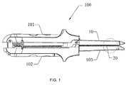
- the linear suturing and cutting device 100 comprises an upper jaw 101 and a lower jaw 102 capable of being closed or opened relative to each other.
- the term "upper” and “lower” herein do not mean to imply to absolutely differentiate the relationship in position, and merely for convenience in description.
- the upper jaw 101 includes an anvil 10.
- the lower jaw 102 includes a staple cartridge frame 103.
- the staple cartridge frame 103 is detachably provided with a staple cartridge 20.
- the upper jaw 101 and the lower jaw 102 can be closed or opened in relative to each other to clamp the target tissues between the anvil 10 and the staple cartridge 20.
- a cutter pushing rod (not shown) and a cutter (not shown) disposed at the distal end of the cutter pushing rod are moveably arranged in the staple cartridge frame 103. The cutter can move from the proximal end to the distal end of the staple cartridge 20 with the force of the cutter pushing rod to cut off the target tissues between the anvil 10 and the staple cartridge 20.
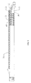
- the staple cartridge 20 is arranged with cartridge holes 21 inside which run throughout the staple cartridge 20 to its working surface and staple pushers 40 disposed in the cartridge holes 21 and being capable of sliding relative to the cartridge holes 21,
- the staple cartridge frame 103 is slidably provided with a firing piece 30 inside, which is configured with a wedge-shape staple pushing member 31 capable of driving the staple pushers 40 to slide in the cartridge holes 21.
- the wedge-shape staple pushing member 31 of the firing piece 30 pushes the staple pushers 40 to move along the cartridge holes 21 so as to fire the staples to suture the tissues.
- the cartridge holes 21 are configured to be inclined towards the distal end of said staple cartridge 20. Since the surface of the wedge-shape staple pushing member 31 engaged with the staple pushers 40 is an inclined staple pushing surface 32 and configured to be sloped upward in the direction from the distal end towards the proximal end, when the wedge-shape staple pushing member 31 moves from the proximal end towards the distal end to push the staple pushers 40 to move, the driving force applied on the staple pushers 40 is also inclined substantially.
- cartridge holes 21 configured to be inclined towards the distal end of the staple cartridge 20
- the wedge-shape staple pushing member 31 has a staple pushing surface 32 engaged with the staple pushers 40, which is acted on the staple pushers 40 directly and applies a force to the staple pushers 40 in the direction which is vertical to the staple pushing surface 32.
- the cartridge holes 21 are vertically arranged relative to the staple pushing surface 32, so as to ensure that the direction of pushing force received by the staple pushers 40 is identical with the extending direction of the cartridge holes 21, which may minimize the friction force between the staple pushers 40 and the inner wall of the cartridge holes 21 during the movement of staple pushers 40 to provide the best smoothness for pushing staples.
- the surfaces of the anvil and the staple cartridge which are disposed face to face are designed to be relatively flat.
- the target tissues clamped between the anvil and the staple cartridge may slide or shift to a certain extent.
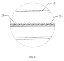
- the upper end surface 211 of each cartridge hole 21 is an upward inclined plane (i.e., the distance to the bottom of the staple cartridge 20 gradually increases) in the extending direction from the distal end towards the proximal end of the staple cartridge 20.
- the working surface of the staple cartridge 20 i.e., the end surface of cartridge hole 21
- the working surface of the staple cartridge 20 is configured correspondingly to be uneven, which can get the target tissues to be clamped between the anvil 10 and the staple cartridge 20 more firmly.
- such a structure is also in concert with the arrangement of the cartridge holes 21 inclined towards the distal end of the staple cartridge 20 in the present embodiment.
- the upper end surface of the cartridge holes is configured to be in other form of inclined state to achieve the similar technical effects of the present embodiment.
- the cartridge holes 21 are configured to be inclined towards the proximal end of the staple cartridge 20, and the firing piece 30 moves from the distal end to the proximal end of the staple cartridge 20, and the wedge-shape staple pushing member 31 has a staple pushing surface 32 engaged with the staple pushers, and the staple pushing surface 32 is configured to be sloped downward in the direction from the distal end towards the proximal end.
- Such a structure can also achieve the technical effects of reducing the friction between the staple pushers and the inner wall of the cartridge holes during the movement of staple pushers 40. But all these variants should be regarded as equivalent variants based on the technical innovation in the present invention, which also should be included within the scope of the present invention.
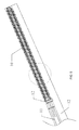
- the staple cartridge 20 includes a cutter groove 22 arranged along the major longitudinal axis thereof.
- the pattern of cartridge holes 21 by either side of the cutter groove 22 presents as that each two adjacent rows of cartridge holes 21 are in a staggered arrangement, which is also for the purpose of better clamping effect and suturing effect on the target tissues when the staple cartridge 20 and the anvil 10 are closed.
- the anvil 10 includes a first anvil unit 11 and at least one second anvil unit 12 which is fixed at either side of the first anvil unit 11, and the first anvil unit 11 and the second anvil units 12 are manufactured separately.
- the anvil 10 is correspondingly arranged with a first anvil unit 11 and two second anvil units 12.
- the anvil can be obtained by manufacturing the first anvil unit and the second anvil unit separately for reducing the forming difficulty of the anvil.
- the first anvil unit 11 and the second anvil unit 12 manufactured separately may be fitted together by subsequent positioning welding, which is convenient for assembly.
- the patterns of cartridge holes 21 by two sides of the cutter groove 22 are symmetrically with each other, such arrangement can reduce forming difficulty of the first anvil unit 11.
- the anvil 10 has a staple forming surface disposed opposite to the staple cartridge 20, wherein, the anvil forming surface 111 corresponding to the first anvil unit 11 and the anvil forming surface 121 corresponding to the second anvil unit 12 are in wave shape.
- the surfaces of the staple cartridge 20 and the anvil 10 which are disposed face to face are overall presented in wavy arrangement which is regular and uniform.
- the staple forming surface is configured to be meshed with the working surface of the staple cartridge 20 to minimize the tissues squeezed out and optimize the clamping effect on the target tissues.
Landscapes
- Health & Medical Sciences (AREA)
- Life Sciences & Earth Sciences (AREA)
- Surgery (AREA)
- Heart & Thoracic Surgery (AREA)
- Engineering & Computer Science (AREA)
- Biomedical Technology (AREA)
- Nuclear Medicine, Radiotherapy & Molecular Imaging (AREA)
- Medical Informatics (AREA)
- Molecular Biology (AREA)
- Animal Behavior & Ethology (AREA)
- General Health & Medical Sciences (AREA)
- Public Health (AREA)
- Veterinary Medicine (AREA)
- Surgical Instruments (AREA)
Applications Claiming Priority (3)
| Application Number | Priority Date | Filing Date | Title |
|---|---|---|---|
| CN201320885569.1U CN203634229U (zh) | 2013-12-31 | 2013-12-31 | 直线缝合切割装置 |
| CN201310747332.1A CN103750872B (zh) | 2013-12-31 | 2013-12-31 | 直线缝合切割装置 |
| PCT/CN2014/094365 WO2015101184A1 (fr) | 2013-12-31 | 2014-12-19 | Dispositif de suture et de découpe linéaires |
Publications (2)
| Publication Number | Publication Date |
|---|---|
| EP3090689A1 true EP3090689A1 (fr) | 2016-11-09 |
| EP3090689A4 EP3090689A4 (fr) | 2017-08-30 |
Family
ID=53493188
Family Applications (1)
| Application Number | Title | Priority Date | Filing Date |
|---|---|---|---|
| EP14877006.8A Withdrawn EP3090689A4 (fr) | 2013-12-31 | 2014-12-19 | Dispositif de suture et de découpe linéaires |
Country Status (4)
| Country | Link |
|---|---|
| US (1) | US20160324519A1 (fr) |
| EP (1) | EP3090689A4 (fr) |
| JP (1) | JP6207750B2 (fr) |
| WO (1) | WO2015101184A1 (fr) |
Family Cites Families (23)
| Publication number | Priority date | Publication date | Assignee | Title |
|---|---|---|---|---|
| JPH0833642A (ja) * | 1994-02-25 | 1996-02-06 | Ethicon Endo Surgery Inc | 外科用ステープラのための改良アンビル承口 |
| RU2063710C1 (ru) * | 1994-04-19 | 1996-07-20 | Сергей Владимирович Колядин | Хирургический сшивающий аппарат для эндоскопических операций и скобка |
| US5941442A (en) * | 1995-10-27 | 1999-08-24 | United States Surgical | Surgical stapler |
| US5865361A (en) * | 1997-09-23 | 1999-02-02 | United States Surgical Corporation | Surgical stapling apparatus |
| US7862579B2 (en) * | 2004-07-28 | 2011-01-04 | Ethicon Endo-Surgery, Inc. | Electroactive polymer-based articulation mechanism for grasper |
| US7635074B2 (en) * | 2005-10-04 | 2009-12-22 | Tyco Healthcare Group Lp | Staple drive assembly |
| US10130359B2 (en) * | 2006-09-29 | 2018-11-20 | Ethicon Llc | Method for forming a staple |
| US8727197B2 (en) * | 2007-03-15 | 2014-05-20 | Ethicon Endo-Surgery, Inc. | Staple cartridge cavity configuration with cooperative surgical staple |
| US8967446B2 (en) * | 2008-05-09 | 2015-03-03 | Covidien Lp | Variable compression surgical fastener cartridge |
| US9016541B2 (en) * | 2008-05-09 | 2015-04-28 | Covidien Lp | Varying tissue compression with an anvil configuration |
| CN201227300Y (zh) * | 2008-06-20 | 2009-04-29 | 华外医疗器械(上海)有限公司 | 可用于内镜切割吻合器以确保钛钉高度恒定的装置 |
| WO2011007351A1 (fr) * | 2009-07-13 | 2011-01-20 | Fund For Medical Research - Rambam Medical Center | Ensemble agrafeuse chirurgicale |
| CN201798769U (zh) * | 2010-08-13 | 2011-04-20 | 李东瑞 | 吻合器的钉仓和推钉片的配合结构 |
| US9877720B2 (en) * | 2010-09-24 | 2018-01-30 | Ethicon Llc | Control features for articulating surgical device |
| CN101966093B (zh) * | 2010-09-28 | 2012-01-11 | 常州市康迪医用吻合器有限公司 | 带有可更换钉仓的腔镜外科切割吻合器 |
| US8474677B2 (en) * | 2010-09-30 | 2013-07-02 | Ethicon Endo-Surgery, Inc. | Fastener system comprising a retention matrix and a cover |
| CN101999917B (zh) * | 2010-12-07 | 2012-09-26 | 苏州天臣国际医疗科技有限公司 | 一种钉仓组件 |
| US9089326B2 (en) * | 2011-10-07 | 2015-07-28 | Ethicon Endo-Surgery, Inc. | Dual staple cartridge for surgical stapler |
| CN103181807B (zh) * | 2011-12-29 | 2016-03-30 | 瑞奇外科器械(中国)有限公司 | 手术缝合器械及其缝钉驱动器 |
| CN104379068B (zh) * | 2012-03-28 | 2017-09-22 | 伊西康内外科公司 | 包括组织厚度补偿件的保持器组件 |
| AU2014236486B2 (en) * | 2013-03-14 | 2019-02-07 | Applied Medical Resources Corporation | Surgical stapler with partial pockets |
| CN203634229U (zh) * | 2013-12-31 | 2014-06-11 | 苏州天臣国际医疗科技有限公司 | 直线缝合切割装置 |
| CN103750872B (zh) * | 2013-12-31 | 2016-05-11 | 苏州天臣国际医疗科技有限公司 | 直线缝合切割装置 |
-
2014
- 2014-12-19 EP EP14877006.8A patent/EP3090689A4/fr not_active Withdrawn
- 2014-12-19 US US15/108,915 patent/US20160324519A1/en not_active Abandoned
- 2014-12-19 JP JP2016542994A patent/JP6207750B2/ja active Active
- 2014-12-19 WO PCT/CN2014/094365 patent/WO2015101184A1/fr not_active Ceased
Also Published As
| Publication number | Publication date |
|---|---|
| JP2017500163A (ja) | 2017-01-05 |
| EP3090689A4 (fr) | 2017-08-30 |
| JP6207750B2 (ja) | 2017-10-04 |
| WO2015101184A1 (fr) | 2015-07-09 |
| US20160324519A1 (en) | 2016-11-10 |
Similar Documents
| Publication | Publication Date | Title |
|---|---|---|
| CN103750872B (zh) | 直线缝合切割装置 | |
| US12471921B2 (en) | Small diameter surgical stapling device | |
| CN107231792B (zh) | 外科线性缝合器 | |
| CN108969039B (zh) | 具有最小死空间的工具组件 | |
| JP6389007B2 (ja) | ステープルカートリッジユニットと当該ステープルカートリッジユニットを使用する医療用ステープラー | |
| US9113869B2 (en) | Pin locking mechanism for a surgical instrument | |
| JP2021023809A (ja) | 超音波骨メスビット及びそれを使用するロボット支援超音波骨パワーシステム | |
| EP3492022A1 (fr) | Mécanisme de réglage de hauteur d'agrafe fermée pour agrafeuse et agrafeuse comprenant ledit mécanisme de réglage | |
| JP2018134408A (ja) | 薄型プッシャを有する外科用器具のための装填ユニット | |
| WO2020244463A1 (fr) | Ensemble cartouche d'agrafes, actionneur d'extrémité et instrument chirurgical associé | |
| US11793517B2 (en) | Linear stapling device with vertically movable knife | |
| CN204542260U (zh) | 改进的执行器及外科器械 | |
| CN104248458B (zh) | 直线吻合器缝合钉仓结构 | |
| EP3090690A1 (fr) | Dispositif de sectionnement et d'agrafage linéaire | |
| WO2024104343A1 (fr) | Enclume et instrument chirurgical | |
| EP3090689A1 (fr) | Dispositif de suture et de découpe linéaires | |
| CN101849851B (zh) | 切割缝合器 | |
| JP2026508783A (ja) | 移動可能なナイフを有するステープルカートリッジ | |
| CN201768000U (zh) | 切割缝合器 | |
| CN223979834U (zh) | 一种用于缝合器械的端部执行器及缝合器械 | |
| CN217118498U (zh) | 钳口组件及外科器械 | |
| CN222303958U (zh) | 一种安全锁定机构及其吻合器 | |
| US11517305B2 (en) | Contoured staple pusher | |
| CN221654421U (zh) | 用于吻合器的端部执行件及吻合器 | |
| CN209203436U (zh) | 一种神经外科手术刀 |
Legal Events
| Date | Code | Title | Description |
|---|---|---|---|
| PUAI | Public reference made under article 153(3) epc to a published international application that has entered the european phase |
Free format text: ORIGINAL CODE: 0009012 |
|
| 17P | Request for examination filed |
Effective date: 20160801 |
|
| AK | Designated contracting states |
Kind code of ref document: A1 Designated state(s): AL AT BE BG CH CY CZ DE DK EE ES FI FR GB GR HR HU IE IS IT LI LT LU LV MC MK MT NL NO PL PT RO RS SE SI SK SM TR |
|
| AX | Request for extension of the european patent |
Extension state: BA ME |
|
| DAX | Request for extension of the european patent (deleted) | ||
| A4 | Supplementary search report drawn up and despatched |
Effective date: 20170802 |
|
| RIC1 | Information provided on ipc code assigned before grant |
Ipc: A61B 17/072 20060101AFI20170727BHEP |
|
| 17Q | First examination report despatched |
Effective date: 20181004 |
|
| STAA | Information on the status of an ep patent application or granted ep patent |
Free format text: STATUS: THE APPLICATION HAS BEEN WITHDRAWN |
|
| 18W | Application withdrawn |
Effective date: 20190122 |