EP3090690B1 - Agrafeuse linéaire coupante - Google Patents
Agrafeuse linéaire coupante Download PDFInfo
- Publication number
- EP3090690B1 EP3090690B1 EP14877249.4A EP14877249A EP3090690B1 EP 3090690 B1 EP3090690 B1 EP 3090690B1 EP 14877249 A EP14877249 A EP 14877249A EP 3090690 B1 EP3090690 B1 EP 3090690B1
- Authority
- EP
- European Patent Office
- Prior art keywords
- cutter
- safety piece
- staple cartridge
- linear cutting
- proximal end
- Prior art date
- Legal status (The legal status is an assumption and is not a legal conclusion. Google has not performed a legal analysis and makes no representation as to the accuracy of the status listed.)
- Active
Links
Images




Classifications
-
- A—HUMAN NECESSITIES
- A61—MEDICAL OR VETERINARY SCIENCE; HYGIENE
- A61B—DIAGNOSIS; SURGERY; IDENTIFICATION
- A61B17/00—Surgical instruments, devices or methods
- A61B17/068—Surgical staplers, e.g. containing multiple staples or clamps
- A61B17/072—Surgical staplers, e.g. containing multiple staples or clamps for applying a row of staples in a single action, e.g. the staples being applied simultaneously
- A61B17/07207—Surgical staplers, e.g. containing multiple staples or clamps for applying a row of staples in a single action, e.g. the staples being applied simultaneously the staples being applied sequentially
-
- A—HUMAN NECESSITIES
- A61—MEDICAL OR VETERINARY SCIENCE; HYGIENE
- A61B—DIAGNOSIS; SURGERY; IDENTIFICATION
- A61B90/00—Instruments, implements or accessories specially adapted for surgery or diagnosis and not covered by any of the groups A61B1/00 - A61B50/00, e.g. for luxation treatment or for protecting wound edges
- A61B90/03—Automatic limiting or abutting means, e.g. for safety
-
- A—HUMAN NECESSITIES
- A61—MEDICAL OR VETERINARY SCIENCE; HYGIENE
- A61B—DIAGNOSIS; SURGERY; IDENTIFICATION
- A61B17/00—Surgical instruments, devices or methods
- A61B17/068—Surgical staplers, e.g. containing multiple staples or clamps
- A61B17/072—Surgical staplers, e.g. containing multiple staples or clamps for applying a row of staples in a single action, e.g. the staples being applied simultaneously
- A61B2017/07214—Stapler heads
- A61B2017/07271—Stapler heads characterised by its cartridge
-
- A—HUMAN NECESSITIES
- A61—MEDICAL OR VETERINARY SCIENCE; HYGIENE
- A61B—DIAGNOSIS; SURGERY; IDENTIFICATION
- A61B17/00—Surgical instruments, devices or methods
- A61B17/068—Surgical staplers, e.g. containing multiple staples or clamps
- A61B17/072—Surgical staplers, e.g. containing multiple staples or clamps for applying a row of staples in a single action, e.g. the staples being applied simultaneously
- A61B2017/07214—Stapler heads
- A61B2017/07285—Stapler heads characterised by its cutter
-
- A—HUMAN NECESSITIES
- A61—MEDICAL OR VETERINARY SCIENCE; HYGIENE
- A61B—DIAGNOSIS; SURGERY; IDENTIFICATION
- A61B90/00—Instruments, implements or accessories specially adapted for surgery or diagnosis and not covered by any of the groups A61B1/00 - A61B50/00, e.g. for luxation treatment or for protecting wound edges
- A61B90/03—Automatic limiting or abutting means, e.g. for safety
- A61B2090/033—Abutting means, stops, e.g. abutting on tissue or skin
- A61B2090/034—Abutting means, stops, e.g. abutting on tissue or skin abutting on parts of the device itself
-
- A—HUMAN NECESSITIES
- A61—MEDICAL OR VETERINARY SCIENCE; HYGIENE
- A61B—DIAGNOSIS; SURGERY; IDENTIFICATION
- A61B90/00—Instruments, implements or accessories specially adapted for surgery or diagnosis and not covered by any of the groups A61B1/00 - A61B50/00, e.g. for luxation treatment or for protecting wound edges
- A61B90/08—Accessories or related features not otherwise provided for
- A61B2090/0807—Indication means
- A61B2090/0811—Indication means for the position of a particular part of an instrument with respect to the rest of the instrument, e.g. position of the anvil of a stapling instrument
- A61B2090/0812—Indication means for the position of a particular part of an instrument with respect to the rest of the instrument, e.g. position of the anvil of a stapling instrument indicating loosening or shifting of parts of an instrument, signaling maladjustment of parts
-
- A—HUMAN NECESSITIES
- A61—MEDICAL OR VETERINARY SCIENCE; HYGIENE
- A61B—DIAGNOSIS; SURGERY; IDENTIFICATION
- A61B90/00—Instruments, implements or accessories specially adapted for surgery or diagnosis and not covered by any of the groups A61B1/00 - A61B50/00, e.g. for luxation treatment or for protecting wound edges
- A61B90/08—Accessories or related features not otherwise provided for
- A61B2090/0814—Preventing re-use
Definitions
- the invention belongs to the technical field of medical apparatus and instruments and particularly relates to a linear cutting stapler.
- Linear cutting staplers are widely used in surgical operations such as wound closure and the closure and excision of internal tissues.
- a typical linear cutting stapler as disclosed in U.S. Pat. No. 5,129,570 performs two functions of stapling and cutting, to remove the redundant tissues while stapling the wound.
- This kind of linear cutting stapler generally includes two jaws (i.e., an upper jaw and a lower jaw), closing handles (i.e., an upper handle and a lower handle) for closing the upper jaw and the lower jaw, an anvil and a staple cartridge arranged opposite to each other at the distal ends of the upper jaw and lower jaw respectively, a firing piece and a cutter pushing rod provided with a cutter at its distal end which are arranged in the staple cartridge and can simultaneously move relative to the staple cartridge, and a button for driving the firing piece and the cutter pushing rod to move. Staples are arranged inside the staple cartridge. The firing piece successively pushes the staple pushers in sequence which then push the staples to the anvil, and the cutter cuts off the tissues between the staple cartridge and the anvil.
- the linear cutting stapler can be used repeatedly by replacing the staple cartridge.
- the tissues need to be cut and sutured more than once, thus the staple cartridge requires to be replaced repeatedly. That is to say, while the surgeon finishes one set of cutting and suturing actions, firstly, reset the stapler, and then open the upper jaw and the lower jaw; secondly, withdraw the stapler from the surgical spot and then replace the staple cartridge for the linear cutting stapler continuing the next set of cutting and suturing operations.
- a safety mechanism disclosed in US20050222616A1 provides a safety lockout disposed on the upper proximal end of the staple cartridge and movable from a locked orientation to an unlocked orientation. Once the stapler is at least partially fired, and if the instrument is opened, the safety lockout automatically moves to the perpendicular orientation due to a spring bias mounting thereof. With the safety lockout in this orientation, the stapler cannot be re-clamped in order to continue or to complete the firing. However, the safety lockout can only prevent the re-clamping of the stapler, but cannot prevent the movement of the cutter. Also, after the stapler is fired, the cutter cannot return to the proximal end of the stapler due to the safety lockout.
- EP2959845 is an intermediate document according to Article 54(3) EPC and discloses several different lockout mechanisms for a surgical stapler.
- An object of the invention is to provide a linear cutting stapler, which can prevent the stapler from second firing action without replacing the used staple cartridge.
- the invention provides a linear cutting stapler comprising an upper jaw and a lower jaw capable of being closed or opened relative to each other, said upper jaw includes an anvil and said lower jaw includes a staple cartridge frame; said staple cartridge frame is detachably provided with a staple cartridge, a cutter pushing rod and a cutter disposed at the distal end of said cutter pushing rod are moveably arranged in said staple cartridge frame, said cutter is capable of moving from a proximal end to a distal end of said staple cartridge with the function of said cutter pushing rod to cut off target tissues between said anvil and said staple cartridge, wherein, said linear cutting stapler further comprises a safety piece mounted on said staple cartridge and being capable of moving upward and downward relative to said staple cartridge; said cutter comprises a slot capable of locking said safety piece and a contact part formed above said slot; while said cutter is placed at the proximal end of said staple cartridge and under an unlocked state, said safety piece is positioned at a first position where it is abutting with the upper wall of
- said contact part extends from a distal end to a proximal end of said cutter, said cutter further comprises a stopper arranged at a proximal end of said slot, and while said safety piece is in the said slot, said safety piece abuts against said stopper if said cutter moves towards the distal end; a notch is formed between the proximal end of said contact part and said stopper and defined by said contact part, said stopper and said slot together, said safety piece is capable of getting into said slot via said notch.
- the bottom wall of said contact part presents being upward sloped or parallel with the moving plane of said cutter.
- the upper wall of said contact part is parallel with the moving plane of said cutter, or presents being downward sloped in the direction from the distal end to the proximal end of said cutter.
- said safety piece is at said free position, said free position is higher or lower than or same height as said second position.
- the proximal end of said stopper is provided with a guiding part, said guiding part comprises a guiding surface for guiding said safety piece from said free position onto the upper wall of said stopper; in the direction from the proximal end to the distal end of said cutter, said guiding surface presents as an upward slope or a cambered surface with smooth transition.
- the proximal end of said guiding surface extends downwards to a position below said free position.
- said safety piece is made of deformable material and has elasticity in the vertical direction.
- the Rockwell Hardness HRC of said safety piece ranges between 28 degrees ⁇ 35 degrees.
- the Rockwell Hardness HRC of said safety piece is 30 degrees.
- said safety piece is detachably mounted on said staple cartridge.
- a pair of side walls of said staple cartridge are respectively provided with a mounting hole for inserting said safety piece, and said mounting hole is a blind hole with its outer end closed.
- said linear cutting stapler further comprises a cutter sheath which is detachably mounted at the proximal end of said staple cartridge, said safety piece is detachably mounted inside the said cutter sheath, and the longitudinal axis of said safety piece along the length direction of safety piece is perpendicular to that of said staple cartridge.
- said cutter sheath comprises two opposite installation walls and an interconnection wall connecting between said two installation walls, said two installation walls are provided with a bump respectively, said staple cartridge is provided with a groove capable of being engaged with said bump.
- said two installation walls are respectively provided with an installation hole for inserting said safety piece, said installation hole is lower than the upper wall of said contact part, said safety piece is made of deformable material, and while said safety piece is abutting against the upper wall of said contact part, said safety piece is under forced deformation state.
- the dimension of said installation hole almost equals to or is slightly larger than the thickness of said safety piece.
- said installation hole is higher or same height as the bottom of said slot.
- the top of said stopper is higher than said installation hole, the proximal end of said stopper is provided with a guiding part, the proximal end of said guiding part is lower than said installation hole.
- said two installation walls are respectively provided with an installation hole for inserting said safety piece
- said safety piece is made of rigid plate, the height dimensions of said installation hole allow said safety piece to ascend to the upper wall of said contact part and to descend to the upper wall of said stopper.
- the safety piece After installation, the safety piece is abutted against the upper wall of the contact part of the cutter and won't fall into the slot below the contact part, thus, the safety piece is under the unlocked state, the cutter and firing piece can move from the proximal end to the distal end of the staple cartridge to finish the process of cutting and stapling. And, while the cutter is pulled back, the safety piece enters into the slot and gets stuck there, and then the safety piece can restrict the movement of the cutter to prevent the stapler from second firing action without replacing the staple cartridge, which can avoid medical accidents.
- proximal end is the end close to the operator
- distal end is the end far away from the operator
- the liner cutting stapler 100 comprises an upper jaw 101 and a lower jaw 102 capable of being closed or opened relative to each other. It should be explained that the terms such as “upper” and “lower” in this description are not intended to imply any absolute relationship of position, but merely for conveniently describing.
- the upper jaw 101 comprises an anvil 50.
- the lower jaw 102 comprises a staple cartridge frame 103 which is detachably provided with a staple cartridge 10.
- the upper jaw 101 and the lower jaw 102 can be closed in relative to each other to clamp the target tissues between the anvil 50 and the staple cartridge 10.
- a cutter pushing rod (not shown) and a cutter 20 disposed at the distal end of the cutter pushing rod are moveably arranged in the staple cartridge frame 103.
- the cutter 20 is capable of moving from the proximal end N to the distal end F of the staple cartridge 10 by the function of the cutter pushing rod to cut off the target tissues between the anvil 50 and the staple cartridge 10.
- the bottom surface S of the cutter 20 is the moving plane S of the cutter 20 moving back and forth between the proximal end and the distal end of the staple cartridge 10.
- the linear cutting stapler 100 further comprises a safety piece 30 arranged fixedly relative to the staple cartridge 10 in a certain direction (The description "arranged fixedly relative to the staple cartridge 10 in a certain direction" herein means the safety piece 30 is mounted on the staple cartridge 10 and capable of moving upward and downward relative to the staple cartridge 10).
- the safety piece 30 is fixed with the staple cartridge 10 in the moving direction of the cutter 20, however, the safety piece 30 can move upward and downward relative to the staple cartridge 10, such as the deformation of safety piece 30 in the upward and downward direction.
- the longitudinal axis of safety piece 30 along the length direction of safety piece 30 is perpendicular to that of the staple cartridge 10.
- the safety piece 30 may be a thin elastic sheet.
- the safety piece 30 may be made of deformable material and easy to be bended in its thickness direction, but the present invention is not limited thereto.
- the linear cutting stapler 100 comprises a cutter sheath 40 which is detachably mounted at the proximal end N of the staple cartridge 10.
- the cutter sheath 40 comprises two installation walls 41 and an interconnection wall 42 connecting between the two installation walls 41.
- the two installation walls 41 are respectively provided with an installation hole 411 for inserting the safety piece 30.
- the two ends of safety piece 30 are engaged with the installation holes 411 in two installation walls 41 so as to be mounted in the cutter sheath 40.
- the two installation walls 41 are provided with a bump 412 respectively, and the staple cartridge 10 is provided with a groove 11 engaged with the bump 412.
- the cutter sheath 40 may be made of deformable material, thus its installation can be performed by applying a counter-force onto the two installation walls 41 to engage the bumps 412 provided on the cutter sheath 40 into the groove 11, so as to fix the cutter sheath 40 with the staple cartridge 10.
- fixation way of "bump and groove” by which the cutter sheath 40 and the staple cartridge 10 are fixed with each other is merely exemplary. In other alternative embodiments, same fixation effect can be realized by other ways such as arranging the groove in the cutter sheath 40 and bump on the staple cartridge 10.
- the way of mounting the safety piece 30 in the cutter sheath 40 which is described herein is just an exemplary example of mounting the safety piece 30 in the staple cartridge 10.
- the safety piece 30 can be directly mounted onto the side wall of the staple cartridge without the cutter sheath 40, a pair of side walls of the staple cartridge are respectively provided with a mounting hole for inserting the safety piece, and the mounting hole is a blind hole with its outer end closed.
- the cutter 20 comprises a slot 21 capable of restricting the safety piece 30. While the safety piece 30 is stuck in the slot 21, the movement of the cutter 20 is also restricted.
- the description herein about restricting the movement of the cutter means the cutter 20 can't be fired to cut off the tissues, and does not mean that the cutter should be fastened or fixed completely.
- a contact part 22 is formed above the slot 21. The upper wall of the contact part 22 can be abutting with the safety piece 30 to prevent the safety piece 30 from getting into the slot 21.
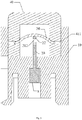
- the safety piece 30 can be selectively positioned at the second position (as shown in Fig.8 , the safety piece 30 is stuck in the slot 21) or the first position (as shown in Fig.5 , the safety piece 30 is abutting with the upper wall of the contact part 22).
- the safety piece 30 may be placed at the first position (namely, the safety piece 30 abutting against the upper wall of the contact part 22), the cutter 20 is under an unlocked state (or, under a standby state before firing), the surgeon can fire the stapler to complete the cutting and stapling actions on target tissues.
- the safety piece 30 is placed at the second position (namely, the safety piece 30 is stuck in the slot 21 provided in the cutter 20), the cutter is under the locked state, thus the stapler can not be fired and the safety insurance preventing the second firing action is realized.
- the safety piece 30 is at a free position after it breaks away from the cutter 20.
- the free position is with a height corresponding to the bottom wall of staple cartridge 10 almost equal to that of the second position (after the safety piece 30 falls into the slot 21, the second position where the safety piece 30 is may be higher than or same height as the inner bottom wall of the slot 21).
- the safety piece 30 may be slightly deformed due to its own elasticity after breaking away from the contact part 22 of the cutter 20, which makes the free position a little higher than the second position.
- the free position may be higher than the second position (but won't higher than the notch 22 described below).
- the free position may be lower than the second position (namely, the height of inner bottom wall of the slot 21 corresponding to the bottom wall of staple cartridge 10 is higher than that of the free position).
- the slot 21 of cutter 20 is capable of locking the safety piece 30, while the cutter 20 moving in the direction from the distal end F to the proximal end N of the staple cartridge 10. After the stapler has been fired once, the cutter should be pulled back from the distal end F of the staple cartridge 10. While the cutter 20 is pulled back to the proximal end N of the staple cartridge 10, the safety piece 30 enters into the slot 21 of the cutter 20 where it gets stuck.
- Such structure can prevent the second firing action while the staple cartridge has been already fired, and be more suitable for the practical operation requirements.
- the contact part 22 is extending from the distal end F1 to the proximal end N1 of the cutter 20.
- the safety piece 30 can fit into the slot 21 via the notch 212.
- the installation hole 411 is lower than the upper wall of the contact part 22 (namely, the installation hole 411 is closer to the bottom wall of the staple cartridge 10 than to the upper wall of the contact part 22), and the inner margin of upper wall of the installation hole 411 transits smoothly, of which such structure can be more suitable for the safety piece 30 with elastic deformation while the safety piece 30 is supported by the upper wall of contact part 22 (namely, the safety piece 30 is at the first position).
- the safety piece 30 may be a thin elastic sheet.
- the safety piece 30 may be made of deformable material and easy to be bended in its thickness direction, thus while the safety piece 30 is abutting against the upper wall of the contact part 22, the safety piece 30 is under a force deformation state in the first position.
- the top of the stopper 24 (namely, the top of the side wall 211 of the slot 21 close to the notch 212) is higher than the installation hole 411.
- the distance between the top of stopper 24 and the bottom wall of the staple cartridge 10 is greater than that between the installation hole 411 and the bottom wall of the staple cartridge 10.
- the proximal end of the stopper 24 (namely, between the side wall 211 of the slot 21 close to the notch 212 and the proximal end N1 of the cutter 20) is provided with a guiding part 23.
- the proximal end of guiding part 23 is lower than the installation hole 411 (namely, the distance between the proximal end of guiding part 23 and the bottom wall of staple cartridge 10 is smaller than that between the installation hole 411 and the bottom wall of staple cartridge 10).
- the safety piece 30 can be jacked up by engaging with the guiding part 23 and then gradually enter into the slot 21 through the top wall of the stopper 24, after that, the safety piece 30 is locked by the side wall 211 to prevent the second firing action.
- the guiding part 23 can guide the safety piece 30 from the free position onto the guiding surface on the top wall of the stopper 24.
- the guiding surface presents as an upward slope or a cambered surface with smooth transition.
- the cambered surface with smooth transition may be an upward protruding arc surface, or a downward protruding arc surface with its guiding end formed like a hook, or a wavy cambered surface with smooth transition.
- the proximal end of guiding surface is extending downward to a position below the free position, which better ensures that the guiding surface can guide the safety piece 30 to move upward and over the stopper 24, after the guiding surface contacts the safety piece 30.
- the safety piece 30 may be a thin elastic sheet or made of deformable material and have elasticity in its thickness direction. Besides, the safety piece 30 requires hardness with certain degree. The hardness degree should not be too large, otherwise the safety piece 30 may not be easily deformed to be jacked up to the first position. And the hardness degree should not be too small, otherwise the safety piece 30 may be deformed plastically at the first position and may not return back to its original form after it leaves the first position, which may cause the safety piece 30 can not easily enter into the notch 212 to realize the function of preventing the second firing action.
- the Rockwell Hardness (HRC) of the safety piece ranges between 28 degrees ⁇ 35 degrees. More preferably, the Rockwell Hardness (HRC) of the safety piece is 30 degrees.
- the distance between the installation hole 411 and the bottom wall of staple cartridge 10 is greater than that between the bottom wall of the slot 21 and the bottom wall of the staple cartridge 10, and the guiding part 23 may be downward sloped in the extending direction from the distal end F1 to the proximal end N1 of the cutter 20 for better guiding the safety piece 30.
- the bottom wall of contact part 22 may be upward sloped (namely, the distance between the bottom wall of contact part 22 and the bottom wall of slot 21 is gradually increase), to coordinate with the guiding part 23 to guide the safety piece 30 into the slot 21 more smoothly.
- the upper wall of the contact part 22 is parallel with the moving plane S of the cutter 20 (the thickness of the contact part 22 is gradually decreased, however, the distance between the upper wall of contact part 22 and the bottom of slot 21 remains unchanged), thus, while the stapler is fired, the firing guide will be more stable and won't cause hindrance in the moving path of cutter 20.
- the bottom wall of contact part 22 is parallel with the moving plane S of the cutter 20 in the extending direction from the distal end F1 to the proximal end N1 of the cutter 20.
- the upper wall of the contact part 22 is slightly downward sloped in the extending direction from the distal end F1 to the proximal end N1 of the cutter 20, and the safety piece 30 will break away from the contact part 22 of the cutter successfully.
- the detailed operational processes of the stapler are as follows. Firstly, inserting the safety piece 30 into the cutter sheath 40 to fix the safety piece 30, and mounting the cutter 20 to the proximal end N of the staple cartridge 10; secondly, buckling up the cutter sheath 40 and the staple cartridge 10 to make the safety piece 30 being abutted against the contact part 22 of the cutter 20, with which the safety piece 30 is forced to have an upward bent deformation (as shown in Fig.5 and 6 ); after the cutter 20 is fired to move, the safety piece 30 is under the free state after it returns back to original shape with its own restoring force; while the one process of cutting and stapling is finished, pulling back the cutter 20 from the distal end F towards the proximal end N of the stapler cartridge 10, then the safety piece 30 is guided by the guiding part 23 of the cutter 20 to rise up a little and subsequently get over the stopper 24 and gradually fall into the slot 21 where it is stuck finally, so as to realize the restrict
- the linear cutting stapler provided by present invention can prevent the stapler from second firing action without replacing the staple cartridge through a special mechanism of the coordination between the safety piece and the cutter, to avoid medical accidents.
- the height h of the installation hole 411 almost equals to the thickness H of the elastic safety piece 30 (with reference to Fig. 8 ).
- the safety piece 30 may be rigid plate, the height dimensions of the installation hole allow the safety piece 30 to ascend to the upper wall of the contact part 22 and to descend to below the upper wall of stopper 24.
Landscapes
- Health & Medical Sciences (AREA)
- Life Sciences & Earth Sciences (AREA)
- Surgery (AREA)
- Molecular Biology (AREA)
- Engineering & Computer Science (AREA)
- Biomedical Technology (AREA)
- Heart & Thoracic Surgery (AREA)
- Medical Informatics (AREA)
- Nuclear Medicine, Radiotherapy & Molecular Imaging (AREA)
- Animal Behavior & Ethology (AREA)
- General Health & Medical Sciences (AREA)
- Public Health (AREA)
- Veterinary Medicine (AREA)
- Oral & Maxillofacial Surgery (AREA)
- Pathology (AREA)
- Surgical Instruments (AREA)
Claims (18)
- Agrafeuse linéaire coupante, comprenant une mâchoire supérieure (101) et une mâchoire inférieure (102) pouvant être fermées ou ouvertes l'une par rapport à l'autre, ladite mâchoire supérieure (101) comprend une enclume (50) et ladite mâchoire inférieure (102) comprend un cadre de cartouche d'agrafes (103) ; ledit cadre de cartouche d'agrafes (103) est muni de manière amovible d'une cartouche d'agrafes (10), une tige de poussée de couteau et un couteau (20) disposé à l'extrémité distale de ladite tige de poussée de couteau sont disposés de manière mobile dans ledit cadre de cartouche d'agrafes (103), ledit couteau (20) est capable de se déplacer d'une extrémité proximale à une extrémité distale de ladite cartouche d'agrafes (10) avec la fonction de ladite tige de poussée de couteau pour couper des tissus cibles entre ladite enclume (50) et ladite cartouche d'agrafes (10), caractérisé en ce que
ladite agrafeuse linéaire coupante comprend en outre une pièce de protection (30) montée sur ladite cartouche d'agrafes (10) et pouvant se déplacer vers le haut et vers le bas par rapport à ladite cartouche d'agrafes (10) ; ledit couteau (20) comprend une fente (21) capable de verrouiller ladite pièce de protection (30), une partie de contact (22) formée au-dessus de ladite fente (21) et s'étendant d'une extrémité distale à une extrémité proximale dudit couteau (20), et un bouchon (24) disposée à une extrémité proximale de ladite fente (21), une encoche (212) est formée entre l'extrémité proximale de ladite partie de contact (22) et ledit bouchon (24) et définie par ladite partie de contact (22), ledit bouchon (24) et ladite fente (21) ensemble ; tandis que ledit couteau (20) est placé à l'extrémité proximale de ladite cartouche d'agrafes (10) et dans un état déverrouillé, ladite pièce de protection (30) est positionnée à une première position où elle est en butée avec la paroi supérieure de ladite partie de contact (22) pour éviter de pénétrer dans ladite fente (21) ; après que ledit couteau (20) se soit détaché de ladite pièce de protection (30), ladite pièce de protection (30) est à une position libre ; et ledit couteau (20) est capable de revenir à l'extrémité proximale de ladite cartouche d'agrafes (10) dans la direction de l'extrémité distale à l'extrémité proximale de ladite cartouche d'agrafes (10) pour se mettre dans un état verrouillé, ladite pièce de protection (30) entre dans ladite fente (21) via ladite encoche (212) pour être positionnée dans une seconde position où elle est coincée dans ladite fente (21), ladite pièce de protection (30) vient en butée contre ledit bouchon (24) si ledit couteau (20) se déplace vers l'extrémité distale. - Agrafeuse linéaire coupante selon la revendication 1, dans laquelle, dans la direction allant de l'extrémité distale à l'extrémité proximale dudit couteau (20), la paroi inférieure de ladite pièce de contact (22) présente une pente ascendante ou parallèle à un plan de déplacement dudit couteau (20).
- Agrafeuse linéaire coupante selon la revendication 2, dans laquelle la paroi supérieure de ladite partie de contact (22) est parallèle au plan de déplacement dudit couteau (20), ou présente une pente ascendante dans la direction allant de l'extrémité distale à l'extrémité proximale dudit couteau (20).
- Agrafeuse linéaire coupante selon la revendication 1, dans laquelle, après que ledit couteau (20) se soit détaché de ladite pièce de protection (30), ladite pièce de protection (30) se trouve dans ladite position libre, ladite position libre étant supérieure ou inférieure à ladite deuxième position ou à la même hauteur que celle-ci.
- Agrafeuse linéaire coupante selon la revendication 4, dans laquelle, l'extrémité proximale dudit bouchon (24) est munie d'une partie de guidage (23), ladite partie de guidage (23) comprend une surface de guidage pour guider ladite pièce de protection (30) depuis ladite position libre sur la paroi supérieure dudit bouchon (24) ; dans la direction allant de l'extrémité proximale à l'extrémité distale dudit couteau (20), ladite surface de guidage se présente sous la forme d'une pente ascendante ou d'une surface cambrée avec une transition lisse.
- Agrafeuse linéaire coupante selon la revendication 5, dans laquelle l'extrémité proximale de ladite surface de guidage s'étend vers le bas jusqu'à une position située en dessous de ladite position libre.
- Agrafeuse linéaire coupante selon la revendication 1, dans laquelle ladite pièce de protection (30) est constituée d'un matériau déformable et possède une élasticité dans la direction verticale.
- Agrafeuse linéaire coupante selon la revendication 1, dans laquelle la dureté Rockwell HRC de ladite pièce de protection (30) est comprise entre 28 degrés et 35 degrés.
- Agrafeuse linéaire coupante selon la revendication 8, dans laquelle la dureté Rockwell HRC de ladite pièce de protection (30) est de 30 degrés.
- Agrafeuse linéaire coupante selon la revendication 1, dans laquelle ladite pièce de protection (30) est montée de manière amovible sur ladite cartouche d'agrafes (10).
- Agrafeuse linéaire coupante selon la revendication 10, dans laquelle une paire de parois latérales de ladite cartouche d'agrafes (10) sont respectivement pourvues d'un trou de montage pour insérer ladite pièce de protection (30), et ledit trou de montage est un trou borgne avec son extrémité extérieure fermée.
- Agrafeuse linéaire coupante selon la revendication 1, comprend en outre un manchon de coupe (40) qui est monté de manière détachable à l'extrémité proximale de ladite cartouche d'agrafes (10), ladite pièce de protection (30) est montée de manière détachable à l'intérieur de ladite manchon de coupe (40), et l'axe longitudinal de ladite pièce de protection (30) le long de la direction longitudinale de la pièce de protection (30) est perpendiculaire à celui de ladite cartouche d'agrafes (10).
- Agrafeuse linéaire coupante selon la revendication 12, dans laquelle, ledit manchon de coupe (40) comprend deux parois d'installation opposées (41) et une paroi d'interconnexion (42) reliant lesdites deux parois d'installation (41), lesdites deux parois d'installation (41) sont pourvues d'une bosse (412) respectivement, ladite cartouche d'agrafes (10) est pourvue d'une rainure (11) pouvant être engagée avec ladite bosse (412).
- Agrafeuse linéaire coupante selon la revendication 13, dans laquelle, lesdites deux parois d'installation sont respectivement pourvues d'un trou d'installation (411) pour l'insertion de ladite pièce de protection (30), ledit trou d'installation (411) est plus bas que la paroi supérieure de ladite partie de contact (22), ladite pièce de protection (30) est réalisée en matériau déformable, et tandis que ladite pièce de protection (30) est en butée contre la paroi supérieure de ladite partie de contact (22), ladite pièce de protection (30) est dans un état de déformation forcée.
- Agrafeuse linéaire coupante selon la revendication 14, dans laquelle la dimension dudit trou d'installation (411) est presque égale ou légèrement supérieure à l'épaisseur de ladite pièce de protection (30).
- Agrafeuse linéaire coupante selon la revendication 14, dans laquelle ledit trou d'installation (411) est plus haut ou à la même hauteur que le fond de ladite fente (21).
- Agrafeuse linéaire coupante selon la revendication 14, dans laquelle le haut de ledit bouchon (24) est plus haut que ledit trou d'installation (411), l'extrémité proximale de ledit bouchon (24) est pourvue d'une partie de guidage (23), l'extrémité proximale de ladite partie de guidage (23) est plus basse que ledit trou d'installation (411).
- Agrafeuse linéaire coupante selon la revendication 13, dans laquelle, lesdites deux parois d'installation (41) sont respectivement pourvues d'un trou d'installation (411) pour l'insertion de ladite pièce de protection (30), ladite pièce de protection (30) est réalisée en plaque rigide, les dimensions en hauteur dudit trou d'installation (411) permettent à ladite pièce de protection (30) de monter jusqu'à la paroi supérieure de ladite partie de contact (22) et de descendre jusqu'à la paroi supérieure dudit bouchon (24).
Applications Claiming Priority (3)
| Application Number | Priority Date | Filing Date | Title |
|---|---|---|---|
| CN201310749269.5A CN103720499B (zh) | 2013-12-31 | 2013-12-31 | 直线缝合切割装置 |
| CN201320887855.1U CN203634231U (zh) | 2013-12-31 | 2013-12-31 | 直线缝合切割装置 |
| PCT/CN2014/095149 WO2015101226A1 (fr) | 2013-12-31 | 2014-12-26 | Dispositif de sectionnement et d'agrafage linéaire |
Publications (3)
| Publication Number | Publication Date |
|---|---|
| EP3090690A1 EP3090690A1 (fr) | 2016-11-09 |
| EP3090690A4 EP3090690A4 (fr) | 2017-09-27 |
| EP3090690B1 true EP3090690B1 (fr) | 2020-07-22 |
Family
ID=53493213
Family Applications (1)
| Application Number | Title | Priority Date | Filing Date |
|---|---|---|---|
| EP14877249.4A Active EP3090690B1 (fr) | 2013-12-31 | 2014-12-26 | Agrafeuse linéaire coupante |
Country Status (5)
| Country | Link |
|---|---|
| US (1) | US10265070B2 (fr) |
| EP (1) | EP3090690B1 (fr) |
| JP (1) | JP6328250B2 (fr) |
| ES (1) | ES2824426T3 (fr) |
| WO (1) | WO2015101226A1 (fr) |
Families Citing this family (7)
| Publication number | Priority date | Publication date | Assignee | Title |
|---|---|---|---|---|
| US10524795B2 (en) * | 2015-07-30 | 2020-01-07 | Ethicon Llc | Surgical instrument comprising systems for permitting the optional transection of tissue |
| US11154300B2 (en) | 2015-07-30 | 2021-10-26 | Cilag Gmbh International | Surgical instrument comprising separate tissue securing and tissue cutting systems |
| US11642126B2 (en) * | 2016-11-04 | 2023-05-09 | Covidien Lp | Surgical stapling apparatus with tissue pockets |
| CN110755123A (zh) * | 2019-11-20 | 2020-02-07 | 无锡市舒康医疗器械有限公司 | 一种防二次击发的钉仓保险装置 |
| CN110811726B (zh) * | 2019-12-16 | 2024-09-24 | 上海博洽医疗器械有限公司 | 腔镜切割吻合器的保险机构 |
| CN111481304B (zh) * | 2020-05-09 | 2024-08-09 | 南微医学科技股份有限公司 | 一种三臂夹 |
| US20250120706A1 (en) * | 2023-10-13 | 2025-04-17 | Cilag Gmbh International | Surgical instruments with jaw and firing actuator lockout arrangements located proximal to a jaw pivot location |
Citations (1)
| Publication number | Priority date | Publication date | Assignee | Title |
|---|---|---|---|---|
| EP2959845A1 (fr) * | 2014-06-25 | 2015-12-30 | Ethicon Endo-Surgery, Inc. | Fonctionnalités de mise en prise de verrouillage pour agrafeuse chirurgicale |
Family Cites Families (31)
| Publication number | Priority date | Publication date | Assignee | Title |
|---|---|---|---|---|
| US4569346A (en) | 1983-03-30 | 1986-02-11 | United States Surgical Corporation | Safety apparatus for surgical occluding and cutting device |
| DE3608146A1 (de) | 1986-03-12 | 1987-09-17 | Hilti Ag | Pulverkraftbetriebenes setzgeraet |
| US4892244A (en) * | 1988-11-07 | 1990-01-09 | Ethicon, Inc. | Surgical stapler cartridge lockout device |
| US4930674A (en) * | 1989-02-24 | 1990-06-05 | Abiomed, Inc. | Surgical stapler |
| US4955959A (en) * | 1989-05-26 | 1990-09-11 | United States Surgical Corporation | Locking mechanism for a surgical fastening apparatus |
| US5156315A (en) * | 1990-09-17 | 1992-10-20 | United States Surgical Corporation | Arcuate apparatus for applying two-part surgical fasteners |
| US5129570A (en) * | 1990-11-30 | 1992-07-14 | Ethicon, Inc. | Surgical stapler |
| US5395034A (en) | 1991-11-07 | 1995-03-07 | American Cyanamid Co. | Linear surgical stapling instrument |
| US5673842A (en) | 1996-03-05 | 1997-10-07 | Ethicon Endo-Surgery | Surgical stapler with locking mechanism |
| US7334717B2 (en) * | 2001-10-05 | 2008-02-26 | Tyco Healthcare Group Lp | Surgical fastener applying apparatus |
| US8453908B2 (en) | 2008-02-13 | 2013-06-04 | Ethicon Endo-Surgery, Inc. | Surgical stapling instrument with improved firing trigger arrangement |
| CA2665017A1 (fr) * | 2008-05-05 | 2009-11-05 | Tyco Healthcare Group Lp | Instrument chirurgical avec clampage et incision sequentiels |
| EP2163209A1 (fr) * | 2008-09-15 | 2010-03-17 | Zhiqiang Weng | Mécanisme de verrouillage pour agrafeuse chirurgicale |
| CN101756738A (zh) | 2008-12-02 | 2010-06-30 | 苏州天臣国际医疗科技有限公司 | 直线型切割闭合器 |
| CN101797174B (zh) | 2010-03-02 | 2011-09-07 | 瑞奇外科器械(北京)有限公司 | 外科用直线切割吻合器的保险装置 |
| CN201768000U (zh) | 2010-06-10 | 2011-03-23 | 苏州天臣国际医疗科技有限公司 | 切割缝合器 |
| US9307989B2 (en) * | 2012-03-28 | 2016-04-12 | Ethicon Endo-Surgery, Llc | Tissue stapler having a thickness compensator incorportating a hydrophobic agent |
| CN101991450B (zh) | 2010-12-07 | 2012-09-19 | 苏州天臣国际医疗科技有限公司 | 直线型缝切器 |
| CN101991453B (zh) | 2010-12-10 | 2012-07-18 | 苏州天臣国际医疗科技有限公司 | 直线型切割缝合器 |
| CN101991452B (zh) * | 2010-12-10 | 2012-07-04 | 苏州天臣国际医疗科技有限公司 | 一种直线型外科装订仪 |
| CN102068290B (zh) | 2010-12-16 | 2013-06-05 | 苏州天臣国际医疗科技有限公司 | 直线型切割缝合器 |
| CN102743201B (zh) | 2011-04-20 | 2014-03-12 | 苏州天臣国际医疗科技有限公司 | 直线型切割缝合器 |
| EP2770921B1 (fr) * | 2011-10-26 | 2019-02-27 | Intuitive Surgical Operations, Inc. | Instrument chirurgical ayant une lame de couteau intégrale |
| CN202446163U (zh) | 2012-01-06 | 2012-09-26 | 江苏瑞普医疗器械科技有限公司 | 直线切割吻合器的推进手柄两侧推进结构 |
| CN202982103U (zh) | 2012-12-18 | 2013-06-12 | 苏州天臣国际医疗科技有限公司 | 一种直线缝合切割装置 |
| CN104902826B (zh) * | 2012-12-31 | 2017-10-27 | 直观外科手术操作公司 | 具有增大的刀间隙的外科手术钉仓 |
| CN203341779U (zh) | 2013-07-17 | 2013-12-18 | 苏州澳力欣精密技术有限公司 | 一种直线型切割吻合器 |
| US9681870B2 (en) * | 2013-12-23 | 2017-06-20 | Ethicon Llc | Articulatable surgical instruments with separate and distinct closing and firing systems |
| CN203634231U (zh) | 2013-12-31 | 2014-06-11 | 苏州天臣国际医疗科技有限公司 | 直线缝合切割装置 |
| CN103720499B (zh) | 2013-12-31 | 2016-02-17 | 苏州天臣国际医疗科技有限公司 | 直线缝合切割装置 |
| US10524795B2 (en) * | 2015-07-30 | 2020-01-07 | Ethicon Llc | Surgical instrument comprising systems for permitting the optional transection of tissue |
-
2014
- 2014-12-26 WO PCT/CN2014/095149 patent/WO2015101226A1/fr not_active Ceased
- 2014-12-26 JP JP2016542761A patent/JP6328250B2/ja active Active
- 2014-12-26 US US15/108,896 patent/US10265070B2/en active Active
- 2014-12-26 ES ES14877249T patent/ES2824426T3/es active Active
- 2014-12-26 EP EP14877249.4A patent/EP3090690B1/fr active Active
Patent Citations (1)
| Publication number | Priority date | Publication date | Assignee | Title |
|---|---|---|---|---|
| EP2959845A1 (fr) * | 2014-06-25 | 2015-12-30 | Ethicon Endo-Surgery, Inc. | Fonctionnalités de mise en prise de verrouillage pour agrafeuse chirurgicale |
Also Published As
| Publication number | Publication date |
|---|---|
| ES2824426T3 (es) | 2021-05-12 |
| US10265070B2 (en) | 2019-04-23 |
| JP2017500155A (ja) | 2017-01-05 |
| JP6328250B2 (ja) | 2018-05-23 |
| WO2015101226A1 (fr) | 2015-07-09 |
| US20170209143A1 (en) | 2017-07-27 |
| EP3090690A1 (fr) | 2016-11-09 |
| EP3090690A4 (fr) | 2017-09-27 |
Similar Documents
| Publication | Publication Date | Title |
|---|---|---|
| EP3090690B1 (fr) | Agrafeuse linéaire coupante | |
| EP3639757B1 (fr) | Mécanisme de découplage pour agrafeuse chirurgicale linéaire | |
| EP3187127B1 (fr) | Agrafeuse chirurgicale ayant un indicateur de fin de course | |
| JP3213928U (ja) | ステープリングヘッドアセンブリ及び内視鏡外科手術縫合切断装置 | |
| US10314581B2 (en) | Reloadable and disposable multifunctional surgical device | |
| EP3318199A1 (fr) | Ensemble d'outil chirurgical comportant un ensemble de tir compact | |
| EP2898839A1 (fr) | Appareil chirurgical | |
| CN113727662A (zh) | 用于直角外科缝合器的组织切割垫圈 | |
| JP2013099611A (ja) | 外科用ステープラのためのアンビル位置検出器 | |
| EP3903693A1 (fr) | Dispositif de sécurité pour instrument chirurgical | |
| EP4706580A2 (fr) | Instrument chirurgical, et ensemble de guidage et outil de démontage associés | |
| CN120957670A (zh) | 具有锁定组件的手术钉合设备 | |
| CN213489060U (zh) | 钉仓组件及具有该钉仓组件的医用吻合器 | |
| CN105796145B (zh) | 一种钉头组件以及腔镜外科手术缝切装置 | |
| CN203634231U (zh) | 直线缝合切割装置 | |
| US20250325266A1 (en) | Surgical stapling device with firing lockout member | |
| CN103720499B (zh) | 直线缝合切割装置 | |
| KR20250151922A (ko) | 수술용 인스트루먼트의 카트리지 및 이를 구비한 수술용 인스트루먼트 | |
| JP2010148693A (ja) | 医療用ステープラ | |
| CN213156138U (zh) | 一种具有空钉仓保护功能的外科缝合器 | |
| CN117979911A (zh) | 具有击发锁定构件的外科缝合装置 | |
| CN202477766U (zh) | 一种带刀缝合器及其击发保险装置 | |
| CN219289563U (zh) | 一种腔镜吻合器 | |
| CN115919392A (zh) | 钉仓组件及医用吻合器 | |
| WO1989004144A1 (fr) | Systeme d'agrafage chirurgical |
Legal Events
| Date | Code | Title | Description |
|---|---|---|---|
| PUAI | Public reference made under article 153(3) epc to a published international application that has entered the european phase |
Free format text: ORIGINAL CODE: 0009012 |
|
| 17P | Request for examination filed |
Effective date: 20160801 |
|
| AK | Designated contracting states |
Kind code of ref document: A1 Designated state(s): AL AT BE BG CH CY CZ DE DK EE ES FI FR GB GR HR HU IE IS IT LI LT LU LV MC MK MT NL NO PL PT RO RS SE SI SK SM TR |
|
| AX | Request for extension of the european patent |
Extension state: BA ME |
|
| DAX | Request for extension of the european patent (deleted) | ||
| A4 | Supplementary search report drawn up and despatched |
Effective date: 20170830 |
|
| RIC1 | Information provided on ipc code assigned before grant |
Ipc: A61B 17/072 20060101AFI20170824BHEP |
|
| GRAP | Despatch of communication of intention to grant a patent |
Free format text: ORIGINAL CODE: EPIDOSNIGR1 |
|
| STAA | Information on the status of an ep patent application or granted ep patent |
Free format text: STATUS: GRANT OF PATENT IS INTENDED |
|
| INTG | Intention to grant announced |
Effective date: 20200131 |
|
| RIN1 | Information on inventor provided before grant (corrected) |
Inventor name: CHEN, WANGDONG Inventor name: PEI, YONGWANG Inventor name: SHU, TUO |
|
| GRAS | Grant fee paid |
Free format text: ORIGINAL CODE: EPIDOSNIGR3 |
|
| GRAA | (expected) grant |
Free format text: ORIGINAL CODE: 0009210 |
|
| STAA | Information on the status of an ep patent application or granted ep patent |
Free format text: STATUS: THE PATENT HAS BEEN GRANTED |
|
| RAP1 | Party data changed (applicant data changed or rights of an application transferred) |
Owner name: TOUCHSTONE INTERNATIONAL MEDICAL SCIENCE CO., LTD. |
|
| AK | Designated contracting states |
Kind code of ref document: B1 Designated state(s): AL AT BE BG CH CY CZ DE DK EE ES FI FR GB GR HR HU IE IS IT LI LT LU LV MC MK MT NL NO PL PT RO RS SE SI SK SM TR |
|
| REG | Reference to a national code |
Ref country code: GB Ref legal event code: FG4D |
|
| REG | Reference to a national code |
Ref country code: CH Ref legal event code: EP |
|
| REG | Reference to a national code |
Ref country code: DE Ref legal event code: R096 Ref document number: 602014068146 Country of ref document: DE |
|
| REG | Reference to a national code |
Ref country code: AT Ref legal event code: REF Ref document number: 1292617 Country of ref document: AT Kind code of ref document: T Effective date: 20200815 |
|
| REG | Reference to a national code |
Ref country code: IE Ref legal event code: FG4D |
|
| REG | Reference to a national code |
Ref country code: CH Ref legal event code: NV Representative=s name: OFFICE ERNEST T. FREYLINGER S.A., CH |
|
| REG | Reference to a national code |
Ref country code: LT Ref legal event code: MG4D |
|
| PG25 | Lapsed in a contracting state [announced via postgrant information from national office to epo] |
Ref country code: NO Free format text: LAPSE BECAUSE OF FAILURE TO SUBMIT A TRANSLATION OF THE DESCRIPTION OR TO PAY THE FEE WITHIN THE PRESCRIBED TIME-LIMIT Effective date: 20201022 Ref country code: SE Free format text: LAPSE BECAUSE OF FAILURE TO SUBMIT A TRANSLATION OF THE DESCRIPTION OR TO PAY THE FEE WITHIN THE PRESCRIBED TIME-LIMIT Effective date: 20200722 Ref country code: BG Free format text: LAPSE BECAUSE OF FAILURE TO SUBMIT A TRANSLATION OF THE DESCRIPTION OR TO PAY THE FEE WITHIN THE PRESCRIBED TIME-LIMIT Effective date: 20201022 Ref country code: GR Free format text: LAPSE BECAUSE OF FAILURE TO SUBMIT A TRANSLATION OF THE DESCRIPTION OR TO PAY THE FEE WITHIN THE PRESCRIBED TIME-LIMIT Effective date: 20201023 Ref country code: LT Free format text: LAPSE BECAUSE OF FAILURE TO SUBMIT A TRANSLATION OF THE DESCRIPTION OR TO PAY THE FEE WITHIN THE PRESCRIBED TIME-LIMIT Effective date: 20200722 Ref country code: HR Free format text: LAPSE BECAUSE OF FAILURE TO SUBMIT A TRANSLATION OF THE DESCRIPTION OR TO PAY THE FEE WITHIN THE PRESCRIBED TIME-LIMIT Effective date: 20200722 Ref country code: PT Free format text: LAPSE BECAUSE OF FAILURE TO SUBMIT A TRANSLATION OF THE DESCRIPTION OR TO PAY THE FEE WITHIN THE PRESCRIBED TIME-LIMIT Effective date: 20201123 Ref country code: FI Free format text: LAPSE BECAUSE OF FAILURE TO SUBMIT A TRANSLATION OF THE DESCRIPTION OR TO PAY THE FEE WITHIN THE PRESCRIBED TIME-LIMIT Effective date: 20200722 |
|
| PG25 | Lapsed in a contracting state [announced via postgrant information from national office to epo] |
Ref country code: IS Free format text: LAPSE BECAUSE OF FAILURE TO SUBMIT A TRANSLATION OF THE DESCRIPTION OR TO PAY THE FEE WITHIN THE PRESCRIBED TIME-LIMIT Effective date: 20201122 Ref country code: PL Free format text: LAPSE BECAUSE OF FAILURE TO SUBMIT A TRANSLATION OF THE DESCRIPTION OR TO PAY THE FEE WITHIN THE PRESCRIBED TIME-LIMIT Effective date: 20200722 Ref country code: LV Free format text: LAPSE BECAUSE OF FAILURE TO SUBMIT A TRANSLATION OF THE DESCRIPTION OR TO PAY THE FEE WITHIN THE PRESCRIBED TIME-LIMIT Effective date: 20200722 Ref country code: RS Free format text: LAPSE BECAUSE OF FAILURE TO SUBMIT A TRANSLATION OF THE DESCRIPTION OR TO PAY THE FEE WITHIN THE PRESCRIBED TIME-LIMIT Effective date: 20200722 |
|
| PG25 | Lapsed in a contracting state [announced via postgrant information from national office to epo] |
Ref country code: NL Free format text: LAPSE BECAUSE OF FAILURE TO SUBMIT A TRANSLATION OF THE DESCRIPTION OR TO PAY THE FEE WITHIN THE PRESCRIBED TIME-LIMIT Effective date: 20200722 |
|
| REG | Reference to a national code |
Ref country code: DE Ref legal event code: R097 Ref document number: 602014068146 Country of ref document: DE |
|
| PG25 | Lapsed in a contracting state [announced via postgrant information from national office to epo] |
Ref country code: EE Free format text: LAPSE BECAUSE OF FAILURE TO SUBMIT A TRANSLATION OF THE DESCRIPTION OR TO PAY THE FEE WITHIN THE PRESCRIBED TIME-LIMIT Effective date: 20200722 Ref country code: RO Free format text: LAPSE BECAUSE OF FAILURE TO SUBMIT A TRANSLATION OF THE DESCRIPTION OR TO PAY THE FEE WITHIN THE PRESCRIBED TIME-LIMIT Effective date: 20200722 Ref country code: SM Free format text: LAPSE BECAUSE OF FAILURE TO SUBMIT A TRANSLATION OF THE DESCRIPTION OR TO PAY THE FEE WITHIN THE PRESCRIBED TIME-LIMIT Effective date: 20200722 Ref country code: CZ Free format text: LAPSE BECAUSE OF FAILURE TO SUBMIT A TRANSLATION OF THE DESCRIPTION OR TO PAY THE FEE WITHIN THE PRESCRIBED TIME-LIMIT Effective date: 20200722 Ref country code: DK Free format text: LAPSE BECAUSE OF FAILURE TO SUBMIT A TRANSLATION OF THE DESCRIPTION OR TO PAY THE FEE WITHIN THE PRESCRIBED TIME-LIMIT Effective date: 20200722 |
|
| REG | Reference to a national code |
Ref country code: ES Ref legal event code: FG2A Ref document number: 2824426 Country of ref document: ES Kind code of ref document: T3 Effective date: 20210512 |
|
| PLBE | No opposition filed within time limit |
Free format text: ORIGINAL CODE: 0009261 |
|
| STAA | Information on the status of an ep patent application or granted ep patent |
Free format text: STATUS: NO OPPOSITION FILED WITHIN TIME LIMIT |
|
| PG25 | Lapsed in a contracting state [announced via postgrant information from national office to epo] |
Ref country code: AL Free format text: LAPSE BECAUSE OF FAILURE TO SUBMIT A TRANSLATION OF THE DESCRIPTION OR TO PAY THE FEE WITHIN THE PRESCRIBED TIME-LIMIT Effective date: 20200722 |
|
| 26N | No opposition filed |
Effective date: 20210423 |
|
| PG25 | Lapsed in a contracting state [announced via postgrant information from national office to epo] |
Ref country code: SK Free format text: LAPSE BECAUSE OF FAILURE TO SUBMIT A TRANSLATION OF THE DESCRIPTION OR TO PAY THE FEE WITHIN THE PRESCRIBED TIME-LIMIT Effective date: 20200722 |
|
| PG25 | Lapsed in a contracting state [announced via postgrant information from national office to epo] |
Ref country code: MC Free format text: LAPSE BECAUSE OF FAILURE TO SUBMIT A TRANSLATION OF THE DESCRIPTION OR TO PAY THE FEE WITHIN THE PRESCRIBED TIME-LIMIT Effective date: 20200722 Ref country code: SI Free format text: LAPSE BECAUSE OF FAILURE TO SUBMIT A TRANSLATION OF THE DESCRIPTION OR TO PAY THE FEE WITHIN THE PRESCRIBED TIME-LIMIT Effective date: 20200722 |
|
| REG | Reference to a national code |
Ref country code: BE Ref legal event code: MM Effective date: 20201231 |
|
| REG | Reference to a national code |
Ref country code: NL Ref legal event code: MP Effective date: 20200722 |
|
| PG25 | Lapsed in a contracting state [announced via postgrant information from national office to epo] |
Ref country code: LU Free format text: LAPSE BECAUSE OF NON-PAYMENT OF DUE FEES Effective date: 20201226 Ref country code: IE Free format text: LAPSE BECAUSE OF NON-PAYMENT OF DUE FEES Effective date: 20201226 |
|
| REG | Reference to a national code |
Ref country code: AT Ref legal event code: UEP Ref document number: 1292617 Country of ref document: AT Kind code of ref document: T Effective date: 20200722 |
|
| PG25 | Lapsed in a contracting state [announced via postgrant information from national office to epo] |
Ref country code: TR Free format text: LAPSE BECAUSE OF FAILURE TO SUBMIT A TRANSLATION OF THE DESCRIPTION OR TO PAY THE FEE WITHIN THE PRESCRIBED TIME-LIMIT Effective date: 20200722 Ref country code: MT Free format text: LAPSE BECAUSE OF FAILURE TO SUBMIT A TRANSLATION OF THE DESCRIPTION OR TO PAY THE FEE WITHIN THE PRESCRIBED TIME-LIMIT Effective date: 20200722 Ref country code: CY Free format text: LAPSE BECAUSE OF FAILURE TO SUBMIT A TRANSLATION OF THE DESCRIPTION OR TO PAY THE FEE WITHIN THE PRESCRIBED TIME-LIMIT Effective date: 20200722 |
|
| PG25 | Lapsed in a contracting state [announced via postgrant information from national office to epo] |
Ref country code: MK Free format text: LAPSE BECAUSE OF FAILURE TO SUBMIT A TRANSLATION OF THE DESCRIPTION OR TO PAY THE FEE WITHIN THE PRESCRIBED TIME-LIMIT Effective date: 20200722 |
|
| PG25 | Lapsed in a contracting state [announced via postgrant information from national office to epo] |
Ref country code: BE Free format text: LAPSE BECAUSE OF NON-PAYMENT OF DUE FEES Effective date: 20201231 |
|
| P01 | Opt-out of the competence of the unified patent court (upc) registered |
Effective date: 20230530 |
|
| PGFP | Annual fee paid to national office [announced via postgrant information from national office to epo] |
Ref country code: DE Payment date: 20241211 Year of fee payment: 11 |
|
| PGFP | Annual fee paid to national office [announced via postgrant information from national office to epo] |
Ref country code: GB Payment date: 20241219 Year of fee payment: 11 |
|
| PGFP | Annual fee paid to national office [announced via postgrant information from national office to epo] |
Ref country code: FR Payment date: 20241224 Year of fee payment: 11 |
|
| PGFP | Annual fee paid to national office [announced via postgrant information from national office to epo] |
Ref country code: AT Payment date: 20241120 Year of fee payment: 11 |
|
| PGFP | Annual fee paid to national office [announced via postgrant information from national office to epo] |
Ref country code: IT Payment date: 20241211 Year of fee payment: 11 |
|
| PGFP | Annual fee paid to national office [announced via postgrant information from national office to epo] |
Ref country code: ES Payment date: 20250107 Year of fee payment: 11 |
|
| PGFP | Annual fee paid to national office [announced via postgrant information from national office to epo] |
Ref country code: CH Payment date: 20250101 Year of fee payment: 11 |