EP3090824B1 - Kreissägeblatt und verfahren zum arbeiten mit dem kreissägeblatt - Google Patents
Kreissägeblatt und verfahren zum arbeiten mit dem kreissägeblatt Download PDFInfo
- Publication number
- EP3090824B1 EP3090824B1 EP16168054.1A EP16168054A EP3090824B1 EP 3090824 B1 EP3090824 B1 EP 3090824B1 EP 16168054 A EP16168054 A EP 16168054A EP 3090824 B1 EP3090824 B1 EP 3090824B1
- Authority
- EP
- European Patent Office
- Prior art keywords
- gullet
- saw blade
- circular saw
- rotation direction
- rake face
- Prior art date
- Legal status (The legal status is an assumption and is not a legal conclusion. Google has not performed a legal analysis and makes no representation as to the accuracy of the status listed.)
- Active
Links
Images

Classifications
-
- B—PERFORMING OPERATIONS; TRANSPORTING
- B23—MACHINE TOOLS; METAL-WORKING NOT OTHERWISE PROVIDED FOR
- B23D—PLANING; SLOTTING; SHEARING; BROACHING; SAWING; FILING; SCRAPING; LIKE OPERATIONS FOR WORKING METAL BY REMOVING MATERIAL, NOT OTHERWISE PROVIDED FOR
- B23D61/00—Tools for sawing machines or sawing devices; Clamping devices for these tools
- B23D61/02—Circular saw blades
-
- B—PERFORMING OPERATIONS; TRANSPORTING
- B23—MACHINE TOOLS; METAL-WORKING NOT OTHERWISE PROVIDED FOR
- B23D—PLANING; SLOTTING; SHEARING; BROACHING; SAWING; FILING; SCRAPING; LIKE OPERATIONS FOR WORKING METAL BY REMOVING MATERIAL, NOT OTHERWISE PROVIDED FOR
- B23D61/00—Tools for sawing machines or sawing devices; Clamping devices for these tools
- B23D61/02—Circular saw blades
- B23D61/021—Types of set; Variable teeth, e.g. variable in height or gullet depth; Varying pitch; Details of gullet
-
- B—PERFORMING OPERATIONS; TRANSPORTING
- B23—MACHINE TOOLS; METAL-WORKING NOT OTHERWISE PROVIDED FOR
- B23D—PLANING; SLOTTING; SHEARING; BROACHING; SAWING; FILING; SCRAPING; LIKE OPERATIONS FOR WORKING METAL BY REMOVING MATERIAL, NOT OTHERWISE PROVIDED FOR
- B23D61/00—Tools for sawing machines or sawing devices; Clamping devices for these tools
- B23D61/02—Circular saw blades
- B23D61/04—Circular saw blades with inserted saw teeth, i.e. the teeth being individually inserted
-
- B—PERFORMING OPERATIONS; TRANSPORTING
- B23—MACHINE TOOLS; METAL-WORKING NOT OTHERWISE PROVIDED FOR
- B23D—PLANING; SLOTTING; SHEARING; BROACHING; SAWING; FILING; SCRAPING; LIKE OPERATIONS FOR WORKING METAL BY REMOVING MATERIAL, NOT OTHERWISE PROVIDED FOR
- B23D65/00—Making tools for sawing machines or sawing devices for use in cutting any kind of material
Definitions
- the present invention relates to a circular saw blade capable of efficiently suppressing scattering of chips rightward and leftward in the direction of the rotational axis of the circular saw blade at the time of cutting a work piece of a synthetic resin, aluminum alloy or the like using a circular saw blade having tips bonded to the periphery of a disk-shaped base metal, and a method of working with the circular saw blade.
- Circular saw blades are popular as means for cutting off and cutting work pieces of various materials (hereinafter referred to as "cutting work").
- the circular saw blades include (1) a circular saw blade having cutting teeth directly formed on the periphery of the disk-shaped base metal at predetermined intervals, and (2) a circular saw blade having gullets formed in the periphery of the disk-shaped base metal at predetermined intervals, and having tips brazed to the base metal in the individual gullets of the circular saw blade, rearward in the rotation direction thereof.
- the materials for the tips may be adequately selected from among materials such as a hard metal according to the materials of various work pieces to be cut, so that the circular saw blade (tipped saw blade) is the main stream in the art.
- Japanese Unexamined Patent Publication No. 2002-347005 discloses a circular saw blade having tips bonded to a base metal and gullets.
- EP 1 661 653 A1 discloses a circular saw blade as per the preambles of appended claims 1 and 2.
- a work piece to be cut with the circular saw blade provided with tips is a hollow member (round pipe, square pipe or the like) such as an extrusion profile or a pultrusion profile of a synthetic resin or an aluminum alloy as the material, the sound of cutting is disadvantageously very noisy.
- a circular saw blade alternately provided with tips whose distal ends are beveled on one side and tips whose distal ends are beveled on both sides are used.
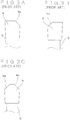
- Figs. 3A to 3C illustrate tips 16 bonded to a disk-shaped base metal 12 of a circular saw blade as observed from the front with the rotation direction of the circular saw blade at the back
- FIG. 3A illustrates the state where a rightward-inclined right side beveling 16a is provided on the distal end of the tip 16.
- Fig. 3B illustrates the state where a leftward-inclined left side beveling 16b is provided on the distal end of the tip 16, and
- Fig. 3C illustrates the state where both side bevelings 16a, 16b are provided on the respective sides of the distal end of the tip 16.
- the central flat portion of the tip 16 beveled on both sides has a radius larger by 0.2 mm than the radius of the one-side beveled flat portion.
- chips which are produced at the time of cutting with the circular saw blade are permitted to intensively fall off directly below in the rotation direction of the circular saw blade, thus effectively suppressing the inconvenience of the chips scattering rightward and leftward in the direction of the rotational axis of the circular saw blade.
- chips which are produced at the time of cutting with the circular saw blade are permitted to intensively fall off directly below in the rotation direction of the circular saw blade, thus effectively suppressing the inconvenience of the chips scattering rightward and leftward in the direction of the rotational axis of the circular saw blade.
- the cutting sound that is produced at the time of cutting a work piece is reduced.
- a hollow face is formed on the rake face of the tip in addition to the invention of claim 1 or claim 2, thereby more effectively suppressing scattering of chips rightward and leftward of the circular saw blade.
- the present invention demonstrates effects of reducing the cutting noise as well as efficiently suppressing scattering of cut chips (chips) rightward and leftward in the direction of the rotational axis of the circular saw blade at the time of cutting work pieces of various materials with the circular saw blade.
- the circular saw blade into which the invention is embodied is what is called a tipped saw blade described above that has tips bonded to the base metal in the individual gullets.
- Figs. 1A and 1B illustrate a first embodiment of a circular saw blade 10 according to the invention, which is the what is called tipped saw blade mentioned above. That is, gullets 14 are recessed in the periphery of a disk-shaped base metal 12 of the circular saw blade 10 at required intervals, and tips 16 of a hard metal or the like as its material are brazed to the individual gullets 14. The position at which the tip 16 is bonded to the base metal 12 in the gullet 14 is a radially extending portion of the gullet 14 in the retreating direction with respect to the rotation direction of the circular saw blade 10, i.e., rearward in the rotation direction.
- each of a gullet bottom 18 and a back portion 20 (which will be described later) in the gullet 14 is configured to extend linearly.
- a bottom closest to the rotation center of the circular saw blade which is referred to as the gullet bottom 18, extends linearly in the tangential direction by a required distance.
- This linear distance D in the gullet bottom 18 is preferably between 3.5 mm and 7.5 mm.
- a portion facing a rake face 22 of the tip 16 bonded to the base metal 12, which is referred to as the back portion 20, also extends linearly by a predetermined distance.
- the upper end of the back portion 20 is contiguous to the bonded portion of the tip 16 bonded to a next gullet 14 provided in the rotation direction of the circular saw blade.
- the rake face 22 is the face that serves to rake chips in front of the rotation direction of the tip 16 of the circular saw blade 10.
- a second back portion 27 of the gullet 14 located below the rake face 22 of the tip 16 and facing the first back portion 20 is linearly shaped.
- the rear portion 26 is an intersection between the extension line of the gullet bottom 18 and the extension line of the second back portion 27.
- a slant angle ⁇ formed by the back portion 20 with respect to a straight line L1 which passes the center of the rotational axis (not shown) of the circular saw blade 10 and the front portion 24 in the rotation direction (to be described later) at the gullet bottom 18, is selected from a range of -5° to 35°.
- the slant angle ⁇ formed by the back portion 20 with respect to the straight line L1 is 34°.
- a slant angle ⁇ formed by the linear gullet bottom 18 of the gullet 14 with respect to a straight line L2 which passes the rotation center of the circular saw blade and the rear portion 26 in the rotation direction at the gullet bottom 18 is between 45° and 100°.
- Fig. 1B is an enlarged view of an encircled portion of the gullet 14 in Fig. 1A , and the intersection of a rightward extension line of the gullet bottom 18, which is a straight line, and a downward extension line of the back portion 20, which is also a straight line, is referred to as "front portion 24." Therefore, the straight line L1 is defined to be a straight line passing the rotation center of the circular saw blade 10 and the front portion 24 which is the intersection of the individual extension lines of the gullet bottom 18 and the back portion 20.
- the gullet bottom 18 and the back portion 20 at the gullet 14 were extended linearly by predetermined distances, the slant angle ⁇ formed by the back portion 20 with respect to the straight line L1 passing the rotation center of the circular saw blade and the front portion 24 in the rotation direction at the gullet bottom 18 was set in the range of -5° to 35°, the slant angle ⁇ formed by the linear gullet bottom 18 of the gullet 14 with respect to the straight line L2 passing the rotation center of the circular saw blade and the rear portion 26 in the rotation direction at the gullet bottom 18 was set to 45° to 100°, and the length D of the gullet bottom 18 was set to 3.5 mm to 7.5 mm, thereby reducing the scattering amount of chips remaining inside a hollow work piece of, for example, an aluminum alloy as the material, by 92% as compared with the conventional circular saw blade illustrated in Figs.
- cutting the work piece with the circular saw blade 10 causes the chips of the work piece to drop intensively directly below the rotation direction of the circular saw blade 10, and thus efficiently suppresses the phenomenon that the chips scatter rightward and leftward in the direction of the rotational axis of the circular saw blade.
- a hollow face is formed on the rake face 22 of the tip 16 illustrated in Fig. 1A in the retreating direction with respect to the rotation direction of the circular saw blade 10.
- this hollow face is a tooth mark of the tip 16 formed into substantially arcuate rake face by forming right and left symmetrical dents in the rake face 22 as viewing the tip 16 in a direction parallel to the rake face 22 from the escaping side of the outer periphery.
- Further forming the hollow face on the rake face 22 of the tip 16 of the circular saw blade 10 according to the first embodiment can reduce the scattering amount of chips at the time of cutting a work piece of, for example, an aluminum alloy as the material, with high efficiency of 99%.
- Square pipes of an aluminum alloy with a thickness of 50 mm ⁇ 1.5 mm were cut at a rotational speed of 3,600 rpm and a feeding speed of 6m/min using a tipped saw blade with an outside diameter of 510 mm, a gullet width of the tips of 3.5 mm, and the number of gullets of 100. After the cutting, the total weight of the chips remaining in each square pipe was measured, and the measurement results were compared.
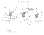
- Fig. 2 illustrates a second embodiment of the circular saw blade 10 according to the invention whose fundamental configuration is the same as the above-described configuration of the first embodiment.
- the dimensions of the circular saw blade 10 according to the second embodiment are set in such a way that the rake face 22 of the tip 16 bonded to the base metal 12 at the gullet 14, and the back portions 20 each facing the rake face 22 with the gullet 14 in between are substantially in parallel to one another.
- the separation distance between the rake face 22 and the back portion 20 of the tip 16 which are substantially in parallel to each other is preferably between 3.5 mm and 7.5 mm; and in this embodiment, the distance was 7.2 mm.
- the circular saw blade 10 can control the scattering direction of chips which are produced at the time of cutting a work piece to lie within a favorable scattering range by specifying the slant angle formed by the gullet bottom 18 at the gullet 14 and the straight line passing the rotation center of the circular saw blade 10 to a certain range. That is, the slant angle ⁇ formed by the gullet bottom 18 of the gullet 14 with respect to the straight line L2, which passes the center of the rotational axis (not shown) of the circular saw blade 10 and the rear portion 26 in the rotation direction (counter direction to the rotation direction) at the gullet bottom 18, is selected from a range of 45° to 60°. In this embodiment, the slant angle ⁇ is 52.5°.
- the rake face 22 of the tip 16 at the gullet 14 and the back portion 20 facing the rake face 22 are set substantially in parallel to each other, and the slant angle ⁇ formed by the gullet bottom 18 of the gullet 14 with respect to the straight line L2 passing the rotation center of the circular saw blade and the rear portion 26 in the rotation direction at the gullet bottom 18 is set to 45° to 60°, making it possible to reduce the scattering amount of chips remaining inside a work piece of an aluminum alloy by 90% as compared with the conventional circular saw blade illustrated in Figs. 3A to 3C .
- the idling noise in the first embodiment is 94 dB
- the idling noise in the second embodiment is reduced to 92 dB.
- forming the hollow face on the rake face 22 of the tip 16 as done in the illustrated circular saw blade 10 of the first embodiment can reduce the scattering amount of chips of a work piece of the aforementioned aluminum alloy to 97%.
- the rake angle of the tip 16 in Fig. 2 is 5° to 25°.
- the rake angle is 10°.
- Square pipes of an aluminum alloy of 50 mm ⁇ 1.5 mm thickness were cut at a rotational speed of 3,600 rpm and a feeding speed of 6m/min using a tipped saw blade with an outside diameter of 510 mm, a gullet width of the tips of 3.5 mm, and the number of gullets of 100. After the cutting, the total weight of the chips remaining in each square pipe was measured, and the measurement results were compared.
- the use of the circular saw blades 10 of the first embodiment and the second embodiment can reduce the rate of scattering chips rightward and leftward in the direction of the rotational axis of the circular saw blade 10 to effectively control the scattering direction due to the Karman's vortex.
- the " Karman's vortex" is academically explained as the behavior of a fluid such that as a columnar object moves in a fluid at an appropriate speed, reversed vortices are produced from the right and left sides of the object, and are aligned in two lines regularly.
- a work piece to be cut with the circular saw blade 10 is of course solid, the aggregate of a large amount of chips produced by the cutting work may be considered as a fluid.
- the circular saw blade according to the invention efficiently suppresses the chips produced at the time of cutting a work piece from scattering rightward and leftward of the circular saw blade, so that when an object to be cut is a hollow work piece, for example, it is possible to significantly reduce undesirable scattering of chips inside the hollow portion of the work piece and residual of the chip therein.
Landscapes
- Engineering & Computer Science (AREA)
- Mechanical Engineering (AREA)
- Sawing (AREA)
- Nonmetal Cutting Devices (AREA)
Claims (4)
- Ein Kreissägeblatt mit Zahnspitzen (16), die an einem Grundmetall (12) in Bezug auf solche gegenüber einem äußeren Rand des Grundmetalls (12) vertiefte Zahnausnehmungen (14) in Drehrichtung rückwärtig angebondet sind, wobeiein Zahnausnehmungsgrund (18) der Zahnausnehmung (14) linear geformt ist, und ein Rückenabschnitt (20) der Zahnausnehmung (14), welcher einer Spanfläche (22) der Zahnspitze (16) zugewandt ist, linear geformt ist,ein vorderer Abschnitt (24) des Zahnausnehmungsgrunds (18) durch einen Schnittpunkt zwischen einer verlängerten Geraden des Zahngrunds (18) und einer verlängerten Geraden des Rückenabschnitts (20) festgelegt ist, und ein hinterer Abschnitt (26) des Zahnausnehmungsgrunds (18) durch einen Schnittpunkt zwischen einer verlängerten Geraden des Zahngrunds (18) und einer verlängerten Geraden eines sich radial erstreckenden Abschnitts (27) der Zahnausnehmung unterhalb der Spanfläche (22) festgelegt ist,ein durch den Rückenabschnitt (20) in Bezug auf eine erste gerade Linie (L1), die sich durch einen Drehmittelpunkt des Kreissägeblatts und den vorderen Abschnitt (24) des Zahnausnehmungsgrunds erstreckt, ausgebildeter Neigungswinkel (Φ) in Drehrichtung zwischen -5° und 35° beträgt,dadurch gekennzeichnet, dassein durch den linearen Zahnausnehmungsgrund (18) in Bezug auf eine zweite gerade Linie (L2), die sich durch den Drehmittelpunkt des Kreissägeblatts und den hinteren Abschnitt (26) erstreckt, ausgebildeter Neigungswinkel (θ) in Drehrichtung zwischen 45° und 100° beträgt, undeine gerade Länge von dem vorderen Abschnitt (24) des Zahnausnehmungsgrunds (18) bis zu dem hinteren Abschnitt (26) des Zahnausnehmungsgrunds (18) zwischen 3,5 mm und 7,5 mm beträgt.
- Ein Kreissägeblatt mit Zahnspitzen (16), die an einem Grundmetall (12) in Bezug auf solche gegenüber einem äußeren Rand des Grundmetalls (12) vertiefte Zahnausnehmungen (14) in Drehrichtung rückwärtig angebondet sind, wobeiein Zahnausnehmungsgrund (18) der Zahnausnehmung (14) linear geformt ist, und ein Rückenabschnitt (20) der Zahnausnehmung (14), welcher einer Spanfläche (22) der Zahnspitze (16) zugewandt ist, linear geformt ist,ein vorderer Abschnitt (24) des Zahnausnehmungsgrunds (18) durch einen Schnittpunkt zwischen einer verlängerten Geraden des Zahngrunds (18) und einer verlängerten Geraden des Rückenabschnitts (20) festgelegt ist, und ein hinterer Abschnitt (26) des Zahnausnehmungsgrunds (18) durch einen Schnittpunkt zwischen einer verlängerten Geraden des Zahngrunds (18) und einer verlängerten Geraden eines sich radial erstreckenden Abschnitts (27) der Zahnausnehmung unterhalb der Spanfläche (22) festgelegt ist,ein durch den Rückenabschnitt (20) in Bezug auf eine erste gerade Linie (L1), die sich durch einen Drehmittelpunkt des Kreissägeblatts und den vorderen Abschnitt (24) des Zahnausnehmungsgrunds erstreckt, ausgebildeter Neigungswinkel (Φ) in Drehrichtung zwischen -5° und 35° beträgt,dadurch gekennzeichnet, dassdie Spanfläche (22) der Zahnspitze (16) in der Zahnausnehmung (14) und der Rückenabschnitt (20), welcher der Spanfläche (22) zugewandt ist, im Wesentlichen parallel zueinander sind, undein durch den linearen Zahnausnehmungsgrund (18) in Bezug auf eine zweite gerade Linie (L2), die sich durch den Drehmittelpunkt des Kreissägeblatts und den hinteren Abschnitt (26) erstreckt, ausgebildeter Neigungswinkel (θ) in Drehrichtung zwischen 45° und 60° beträgt.
- Das Kreissägeblatt gemäß Anspruch 1 oder 2, wobei die Spanfläche (22) der Zahnspitze (16) eine Hohlfläche besitzt, die in rückwärtiger Richtung in Bezug auf die Drehrichtung des Kreissägeblatts eingedrückt ist.
- Ein Verfahren zum Arbeiten mit der Kreissäge gemäß einem der Ansprüche 1 bis 3, wobei das Kreissägeblatt ein Extrusionsprofil oder ein Pultrusionsprofil einer Aluminiumlegierung als Material schneidet.
Applications Claiming Priority (1)
| Application Number | Priority Date | Filing Date | Title |
|---|---|---|---|
| JP2015095149A JP2016209950A (ja) | 2015-05-07 | 2015-05-07 | 丸鋸および丸鋸による加工方法 |
Publications (2)
| Publication Number | Publication Date |
|---|---|
| EP3090824A1 EP3090824A1 (de) | 2016-11-09 |
| EP3090824B1 true EP3090824B1 (de) | 2021-11-17 |
Family
ID=55910828
Family Applications (1)
| Application Number | Title | Priority Date | Filing Date |
|---|---|---|---|
| EP16168054.1A Active EP3090824B1 (de) | 2015-05-07 | 2016-05-03 | Kreissägeblatt und verfahren zum arbeiten mit dem kreissägeblatt |
Country Status (3)
| Country | Link |
|---|---|
| EP (1) | EP3090824B1 (de) |
| JP (1) | JP2016209950A (de) |
| CN (1) | CN106112120B (de) |
Families Citing this family (6)
| Publication number | Priority date | Publication date | Assignee | Title |
|---|---|---|---|---|
| CA3089984C (en) | 2018-02-07 | 2023-09-26 | Vermeer Manufacturing Company | Cutter mounting systems and cutters for the same |
| USD909436S1 (en) | 2019-01-17 | 2021-02-02 | Vermeer Manufacturing Company | Cutter |
| USD939599S1 (en) | 2019-02-07 | 2021-12-28 | Vermeer Manufacturing Company | Cutter |
| USD945505S1 (en) | 2019-08-07 | 2022-03-08 | Vermeer Manufacturing Company | Cutter |
| USD1055121S1 (en) | 2022-01-24 | 2024-12-24 | Vermeer Manufacturing Company | Cutter |
| USD1107081S1 (en) | 2024-09-12 | 2025-12-23 | Vermeer Manufacturing Company | Cutter |
Family Cites Families (12)
| Publication number | Priority date | Publication date | Assignee | Title |
|---|---|---|---|---|
| US3981216A (en) * | 1973-06-06 | 1976-09-21 | Lemmon & Snoap Co. | Low noise, high speed saw blade |
| US4114494A (en) * | 1976-02-12 | 1978-09-19 | Budke Robert L | Noise-controlled circular saw blade |
| JPS5924914A (ja) * | 1982-08-03 | 1984-02-08 | クリード・ツール・カンパニー | 円形ソウブレ−ド |
| JPH09216121A (ja) * | 1996-02-14 | 1997-08-19 | Tsune Wagner Carbide:Kk | 丸 鋸 |
| JP2002347005A (ja) * | 2001-05-25 | 2002-12-04 | Kanefusa Corp | チップソー |
| JP4136893B2 (ja) * | 2003-10-17 | 2008-08-20 | 兼房株式会社 | 円盤状工具 |
| DE102004056854A1 (de) * | 2004-11-25 | 2006-06-01 | Hilti Ag | Stammblatt für ein Kreissägeblatt mit Mineral-Schneidsegmenten |
| EP1700661B1 (de) * | 2005-03-08 | 2007-05-16 | Ledermann GmbH & Co. KG | Kreissägeblatt |
| JP5238406B2 (ja) * | 2008-08-20 | 2013-07-17 | 株式会社アマダ | 帯鋸刃 |
| JP5173670B2 (ja) * | 2008-08-20 | 2013-04-03 | 株式会社アマダ | 鋸刃及びその製造方法 |
| JP5600029B2 (ja) * | 2010-04-19 | 2014-10-01 | アクトテック株式会社 | 回転鋸 |
| WO2013098963A1 (ja) * | 2011-12-27 | 2013-07-04 | 株式会社谷テック | 金属切断用チップソー |
-
2015
- 2015-05-07 JP JP2015095149A patent/JP2016209950A/ja active Pending
-
2016
- 2016-05-03 EP EP16168054.1A patent/EP3090824B1/de active Active
- 2016-05-06 CN CN201610295391.3A patent/CN106112120B/zh active Active
Non-Patent Citations (1)
| Title |
|---|
| None * |
Also Published As
| Publication number | Publication date |
|---|---|
| JP2016209950A (ja) | 2016-12-15 |
| EP3090824A1 (de) | 2016-11-09 |
| CN106112120B (zh) | 2019-02-26 |
| CN106112120A (zh) | 2016-11-16 |
Similar Documents
| Publication | Publication Date | Title |
|---|---|---|
| EP3090824A1 (de) | Kreissägeblatt und verfahren zum arbeiten mit dem kreissägeblatt | |
| EP2602042B1 (de) | Sägeblatt mit Zahnformschutz | |
| AU2014203606B2 (en) | Hole cutter | |
| KR20110126113A (ko) | 칩 브레이커 패턴을 가진 회전 절삭 공구 | |
| US10960476B2 (en) | Tipped circular saw blade | |
| US6939092B2 (en) | Sheet metal hole cutter | |
| US20090126205A1 (en) | Saw Blade With Round Cutting Edges | |
| JP2016083733A (ja) | 切削インサート | |
| US20160001383A1 (en) | Circular saw blade | |
| US20150367433A1 (en) | Saw blade having integrated swarf space | |
| WO2014157135A1 (ja) | ドリル用インサートおよび刃先交換式ドリル | |
| EP3305450B1 (de) | Kreissägeblatt mit spitzen | |
| JP3896127B2 (ja) | チップソー | |
| US20230083825A1 (en) | Circular saw blade | |
| JP3197520B2 (ja) | ダイヤモンドチップソー | |
| JP2011178138A (ja) | チップソー | |
| JP2906136B2 (ja) | 丸 鋸 | |
| JP4164708B2 (ja) | 丸鋸 | |
| JP2015051475A (ja) | 切削インサート及び切削工具 | |
| JP4756609B2 (ja) | 回転切削工具 | |
| JP3088953U (ja) | 回転鋸 | |
| KR200308615Y1 (ko) | 다이아몬드 원형톱 | |
| JP6115789B2 (ja) | 窯業系外装材切削用の回転カッター | |
| JP2006297526A (ja) | 鋸刃 | |
| KR20160015434A (ko) | 형강재 절단용 원형톱 |
Legal Events
| Date | Code | Title | Description |
|---|---|---|---|
| PUAI | Public reference made under article 153(3) epc to a published international application that has entered the european phase |
Free format text: ORIGINAL CODE: 0009012 |
|
| AK | Designated contracting states |
Kind code of ref document: A1 Designated state(s): AL AT BE BG CH CY CZ DE DK EE ES FI FR GB GR HR HU IE IS IT LI LT LU LV MC MK MT NL NO PL PT RO RS SE SI SK SM TR |
|
| AX | Request for extension of the european patent |
Extension state: BA ME |
|
| STAA | Information on the status of an ep patent application or granted ep patent |
Free format text: STATUS: REQUEST FOR EXAMINATION WAS MADE |
|
| 17P | Request for examination filed |
Effective date: 20170309 |
|
| RBV | Designated contracting states (corrected) |
Designated state(s): AL AT BE BG CH CY CZ DE DK EE ES FI FR GB GR HR HU IE IS IT LI LT LU LV MC MK MT NL NO PL PT RO RS SE SI SK SM TR |
|
| STAA | Information on the status of an ep patent application or granted ep patent |
Free format text: STATUS: EXAMINATION IS IN PROGRESS |
|
| 17Q | First examination report despatched |
Effective date: 20200924 |
|
| GRAP | Despatch of communication of intention to grant a patent |
Free format text: ORIGINAL CODE: EPIDOSNIGR1 |
|
| STAA | Information on the status of an ep patent application or granted ep patent |
Free format text: STATUS: GRANT OF PATENT IS INTENDED |
|
| RIC1 | Information provided on ipc code assigned before grant |
Ipc: B23D 61/02 20060101AFI20210518BHEP Ipc: B23D 61/04 20060101ALN20210518BHEP |
|
| INTG | Intention to grant announced |
Effective date: 20210611 |
|
| GRAS | Grant fee paid |
Free format text: ORIGINAL CODE: EPIDOSNIGR3 |
|
| GRAA | (expected) grant |
Free format text: ORIGINAL CODE: 0009210 |
|
| STAA | Information on the status of an ep patent application or granted ep patent |
Free format text: STATUS: THE PATENT HAS BEEN GRANTED |
|
| AK | Designated contracting states |
Kind code of ref document: B1 Designated state(s): AL AT BE BG CH CY CZ DE DK EE ES FI FR GB GR HR HU IE IS IT LI LT LU LV MC MK MT NL NO PL PT RO RS SE SI SK SM TR |
|
| REG | Reference to a national code |
Ref country code: GB Ref legal event code: FG4D |
|
| REG | Reference to a national code |
Ref country code: DE Ref legal event code: R096 Ref document number: 602016066242 Country of ref document: DE |
|
| REG | Reference to a national code |
Ref country code: IE Ref legal event code: FG4D |
|
| REG | Reference to a national code |
Ref country code: AT Ref legal event code: REF Ref document number: 1447649 Country of ref document: AT Kind code of ref document: T Effective date: 20211215 |
|
| REG | Reference to a national code |
Ref country code: LT Ref legal event code: MG9D |
|
| REG | Reference to a national code |
Ref country code: NL Ref legal event code: MP Effective date: 20211117 |
|
| REG | Reference to a national code |
Ref country code: AT Ref legal event code: MK05 Ref document number: 1447649 Country of ref document: AT Kind code of ref document: T Effective date: 20211117 |
|
| PG25 | Lapsed in a contracting state [announced via postgrant information from national office to epo] |
Ref country code: RS Free format text: LAPSE BECAUSE OF FAILURE TO SUBMIT A TRANSLATION OF THE DESCRIPTION OR TO PAY THE FEE WITHIN THE PRESCRIBED TIME-LIMIT Effective date: 20211117 Ref country code: LT Free format text: LAPSE BECAUSE OF FAILURE TO SUBMIT A TRANSLATION OF THE DESCRIPTION OR TO PAY THE FEE WITHIN THE PRESCRIBED TIME-LIMIT Effective date: 20211117 Ref country code: FI Free format text: LAPSE BECAUSE OF FAILURE TO SUBMIT A TRANSLATION OF THE DESCRIPTION OR TO PAY THE FEE WITHIN THE PRESCRIBED TIME-LIMIT Effective date: 20211117 Ref country code: BG Free format text: LAPSE BECAUSE OF FAILURE TO SUBMIT A TRANSLATION OF THE DESCRIPTION OR TO PAY THE FEE WITHIN THE PRESCRIBED TIME-LIMIT Effective date: 20220217 Ref country code: AT Free format text: LAPSE BECAUSE OF FAILURE TO SUBMIT A TRANSLATION OF THE DESCRIPTION OR TO PAY THE FEE WITHIN THE PRESCRIBED TIME-LIMIT Effective date: 20211117 |
|
| PG25 | Lapsed in a contracting state [announced via postgrant information from national office to epo] |
Ref country code: IS Free format text: LAPSE BECAUSE OF FAILURE TO SUBMIT A TRANSLATION OF THE DESCRIPTION OR TO PAY THE FEE WITHIN THE PRESCRIBED TIME-LIMIT Effective date: 20220317 Ref country code: SE Free format text: LAPSE BECAUSE OF FAILURE TO SUBMIT A TRANSLATION OF THE DESCRIPTION OR TO PAY THE FEE WITHIN THE PRESCRIBED TIME-LIMIT Effective date: 20211117 Ref country code: PT Free format text: LAPSE BECAUSE OF FAILURE TO SUBMIT A TRANSLATION OF THE DESCRIPTION OR TO PAY THE FEE WITHIN THE PRESCRIBED TIME-LIMIT Effective date: 20220317 Ref country code: PL Free format text: LAPSE BECAUSE OF FAILURE TO SUBMIT A TRANSLATION OF THE DESCRIPTION OR TO PAY THE FEE WITHIN THE PRESCRIBED TIME-LIMIT Effective date: 20211117 Ref country code: NO Free format text: LAPSE BECAUSE OF FAILURE TO SUBMIT A TRANSLATION OF THE DESCRIPTION OR TO PAY THE FEE WITHIN THE PRESCRIBED TIME-LIMIT Effective date: 20220217 Ref country code: NL Free format text: LAPSE BECAUSE OF FAILURE TO SUBMIT A TRANSLATION OF THE DESCRIPTION OR TO PAY THE FEE WITHIN THE PRESCRIBED TIME-LIMIT Effective date: 20211117 Ref country code: LV Free format text: LAPSE BECAUSE OF FAILURE TO SUBMIT A TRANSLATION OF THE DESCRIPTION OR TO PAY THE FEE WITHIN THE PRESCRIBED TIME-LIMIT Effective date: 20211117 Ref country code: HR Free format text: LAPSE BECAUSE OF FAILURE TO SUBMIT A TRANSLATION OF THE DESCRIPTION OR TO PAY THE FEE WITHIN THE PRESCRIBED TIME-LIMIT Effective date: 20211117 Ref country code: GR Free format text: LAPSE BECAUSE OF FAILURE TO SUBMIT A TRANSLATION OF THE DESCRIPTION OR TO PAY THE FEE WITHIN THE PRESCRIBED TIME-LIMIT Effective date: 20220218 Ref country code: ES Free format text: LAPSE BECAUSE OF FAILURE TO SUBMIT A TRANSLATION OF THE DESCRIPTION OR TO PAY THE FEE WITHIN THE PRESCRIBED TIME-LIMIT Effective date: 20211117 |
|
| PG25 | Lapsed in a contracting state [announced via postgrant information from national office to epo] |
Ref country code: SM Free format text: LAPSE BECAUSE OF FAILURE TO SUBMIT A TRANSLATION OF THE DESCRIPTION OR TO PAY THE FEE WITHIN THE PRESCRIBED TIME-LIMIT Effective date: 20211117 Ref country code: SK Free format text: LAPSE BECAUSE OF FAILURE TO SUBMIT A TRANSLATION OF THE DESCRIPTION OR TO PAY THE FEE WITHIN THE PRESCRIBED TIME-LIMIT Effective date: 20211117 Ref country code: RO Free format text: LAPSE BECAUSE OF FAILURE TO SUBMIT A TRANSLATION OF THE DESCRIPTION OR TO PAY THE FEE WITHIN THE PRESCRIBED TIME-LIMIT Effective date: 20211117 Ref country code: EE Free format text: LAPSE BECAUSE OF FAILURE TO SUBMIT A TRANSLATION OF THE DESCRIPTION OR TO PAY THE FEE WITHIN THE PRESCRIBED TIME-LIMIT Effective date: 20211117 Ref country code: DK Free format text: LAPSE BECAUSE OF FAILURE TO SUBMIT A TRANSLATION OF THE DESCRIPTION OR TO PAY THE FEE WITHIN THE PRESCRIBED TIME-LIMIT Effective date: 20211117 Ref country code: CZ Free format text: LAPSE BECAUSE OF FAILURE TO SUBMIT A TRANSLATION OF THE DESCRIPTION OR TO PAY THE FEE WITHIN THE PRESCRIBED TIME-LIMIT Effective date: 20211117 |
|
| REG | Reference to a national code |
Ref country code: DE Ref legal event code: R097 Ref document number: 602016066242 Country of ref document: DE |
|
| PLBE | No opposition filed within time limit |
Free format text: ORIGINAL CODE: 0009261 |
|
| STAA | Information on the status of an ep patent application or granted ep patent |
Free format text: STATUS: NO OPPOSITION FILED WITHIN TIME LIMIT |
|
| 26N | No opposition filed |
Effective date: 20220818 |
|
| PG25 | Lapsed in a contracting state [announced via postgrant information from national office to epo] |
Ref country code: AL Free format text: LAPSE BECAUSE OF FAILURE TO SUBMIT A TRANSLATION OF THE DESCRIPTION OR TO PAY THE FEE WITHIN THE PRESCRIBED TIME-LIMIT Effective date: 20211117 |
|
| PG25 | Lapsed in a contracting state [announced via postgrant information from national office to epo] |
Ref country code: SI Free format text: LAPSE BECAUSE OF FAILURE TO SUBMIT A TRANSLATION OF THE DESCRIPTION OR TO PAY THE FEE WITHIN THE PRESCRIBED TIME-LIMIT Effective date: 20211117 |
|
| REG | Reference to a national code |
Ref country code: CH Ref legal event code: PL |
|
| REG | Reference to a national code |
Ref country code: BE Ref legal event code: MM Effective date: 20220531 |
|
| GBPC | Gb: european patent ceased through non-payment of renewal fee |
Effective date: 20220503 |
|
| PG25 | Lapsed in a contracting state [announced via postgrant information from national office to epo] |
Ref country code: MC Free format text: LAPSE BECAUSE OF FAILURE TO SUBMIT A TRANSLATION OF THE DESCRIPTION OR TO PAY THE FEE WITHIN THE PRESCRIBED TIME-LIMIT Effective date: 20211117 Ref country code: LU Free format text: LAPSE BECAUSE OF NON-PAYMENT OF DUE FEES Effective date: 20220503 Ref country code: LI Free format text: LAPSE BECAUSE OF NON-PAYMENT OF DUE FEES Effective date: 20220531 Ref country code: CH Free format text: LAPSE BECAUSE OF NON-PAYMENT OF DUE FEES Effective date: 20220531 |
|
| PG25 | Lapsed in a contracting state [announced via postgrant information from national office to epo] |
Ref country code: IE Free format text: LAPSE BECAUSE OF NON-PAYMENT OF DUE FEES Effective date: 20220503 Ref country code: FR Free format text: LAPSE BECAUSE OF NON-PAYMENT OF DUE FEES Effective date: 20220531 |
|
| PG25 | Lapsed in a contracting state [announced via postgrant information from national office to epo] |
Ref country code: IT Free format text: LAPSE BECAUSE OF FAILURE TO SUBMIT A TRANSLATION OF THE DESCRIPTION OR TO PAY THE FEE WITHIN THE PRESCRIBED TIME-LIMIT Effective date: 20211117 Ref country code: GB Free format text: LAPSE BECAUSE OF NON-PAYMENT OF DUE FEES Effective date: 20220503 Ref country code: BE Free format text: LAPSE BECAUSE OF NON-PAYMENT OF DUE FEES Effective date: 20220531 |
|
| PG25 | Lapsed in a contracting state [announced via postgrant information from national office to epo] |
Ref country code: HU Free format text: LAPSE BECAUSE OF FAILURE TO SUBMIT A TRANSLATION OF THE DESCRIPTION OR TO PAY THE FEE WITHIN THE PRESCRIBED TIME-LIMIT; INVALID AB INITIO Effective date: 20160503 |
|
| PG25 | Lapsed in a contracting state [announced via postgrant information from national office to epo] |
Ref country code: MK Free format text: LAPSE BECAUSE OF FAILURE TO SUBMIT A TRANSLATION OF THE DESCRIPTION OR TO PAY THE FEE WITHIN THE PRESCRIBED TIME-LIMIT Effective date: 20211117 Ref country code: CY Free format text: LAPSE BECAUSE OF FAILURE TO SUBMIT A TRANSLATION OF THE DESCRIPTION OR TO PAY THE FEE WITHIN THE PRESCRIBED TIME-LIMIT Effective date: 20211117 |
|
| PG25 | Lapsed in a contracting state [announced via postgrant information from national office to epo] |
Ref country code: MT Free format text: LAPSE BECAUSE OF FAILURE TO SUBMIT A TRANSLATION OF THE DESCRIPTION OR TO PAY THE FEE WITHIN THE PRESCRIBED TIME-LIMIT Effective date: 20211117 |
|
| PGFP | Annual fee paid to national office [announced via postgrant information from national office to epo] |
Ref country code: DE Payment date: 20250521 Year of fee payment: 10 |
|
| PG25 | Lapsed in a contracting state [announced via postgrant information from national office to epo] |
Ref country code: TR Free format text: LAPSE BECAUSE OF FAILURE TO SUBMIT A TRANSLATION OF THE DESCRIPTION OR TO PAY THE FEE WITHIN THE PRESCRIBED TIME-LIMIT Effective date: 20211117 |