EP3090831A1 - Système de changement rapide d'outil comprenant un dispositif de guidage de copeaux - Google Patents
Système de changement rapide d'outil comprenant un dispositif de guidage de copeaux Download PDFInfo
- Publication number
- EP3090831A1 EP3090831A1 EP16167743.0A EP16167743A EP3090831A1 EP 3090831 A1 EP3090831 A1 EP 3090831A1 EP 16167743 A EP16167743 A EP 16167743A EP 3090831 A1 EP3090831 A1 EP 3090831A1
- Authority
- EP
- European Patent Office
- Prior art keywords
- tool
- quick
- change system
- interface
- torque arm
- Prior art date
- Legal status (The legal status is an assumption and is not a legal conclusion. Google has not performed a legal analysis and makes no representation as to the accuracy of the status listed.)
- Granted
Links
Images
Classifications
-
- B—PERFORMING OPERATIONS; TRANSPORTING
- B23—MACHINE TOOLS; METAL-WORKING NOT OTHERWISE PROVIDED FOR
- B23Q—DETAILS, COMPONENTS, OR ACCESSORIES FOR MACHINE TOOLS, e.g. ARRANGEMENTS FOR COPYING OR CONTROLLING; MACHINE TOOLS IN GENERAL CHARACTERISED BY THE CONSTRUCTION OF PARTICULAR DETAILS OR COMPONENTS; COMBINATIONS OR ASSOCIATIONS OF METAL-WORKING MACHINES, NOT DIRECTED TO A PARTICULAR RESULT
- B23Q11/00—Accessories fitted to machine tools for keeping tools or parts of the machine in good working condition or for cooling work; Safety devices specially combined with or arranged in, or specially adapted for use in connection with, machine tools
- B23Q11/08—Protective coverings for parts of machine tools; Splash guards
-
- B—PERFORMING OPERATIONS; TRANSPORTING
- B23—MACHINE TOOLS; METAL-WORKING NOT OTHERWISE PROVIDED FOR
- B23Q—DETAILS, COMPONENTS, OR ACCESSORIES FOR MACHINE TOOLS, e.g. ARRANGEMENTS FOR COPYING OR CONTROLLING; MACHINE TOOLS IN GENERAL CHARACTERISED BY THE CONSTRUCTION OF PARTICULAR DETAILS OR COMPONENTS; COMBINATIONS OR ASSOCIATIONS OF METAL-WORKING MACHINES, NOT DIRECTED TO A PARTICULAR RESULT
- B23Q3/00—Devices holding, supporting, or positioning work or tools, of a kind normally removable from the machine
- B23Q3/155—Arrangements for automatic insertion or removal of tools, e.g. combined with manual handling
- B23Q3/157—Arrangements for automatic insertion or removal of tools, e.g. combined with manual handling of rotary tools
-
- B—PERFORMING OPERATIONS; TRANSPORTING
- B23—MACHINE TOOLS; METAL-WORKING NOT OTHERWISE PROVIDED FOR
- B23Q—DETAILS, COMPONENTS, OR ACCESSORIES FOR MACHINE TOOLS, e.g. ARRANGEMENTS FOR COPYING OR CONTROLLING; MACHINE TOOLS IN GENERAL CHARACTERISED BY THE CONSTRUCTION OF PARTICULAR DETAILS OR COMPONENTS; COMBINATIONS OR ASSOCIATIONS OF METAL-WORKING MACHINES, NOT DIRECTED TO A PARTICULAR RESULT
- B23Q2220/00—Machine tool components
- B23Q2220/008—Rotatable tool holders coupled in parallel to a non rotating accessory
Definitions
- the invention relates to a quick tool change system for machine tools for processing preferably plate-shaped workpieces, which preferably at least partially made of wood, wood materials or plastic.
- the system comprises a tool interface for exchanging and exchanging machining tools, a torque arm which is non-rotatably connectable to a tool mount of the machine tool, and a chip deflector with a chip deflector, which dissipates the chips after separation from the workpiece and is firmly connected to the torque arm.
- chip deflectors In the machining of workpieces, which preferably consist of wood, wood materials, plastics or the like, chips are produced in the working area of the machine. In order to bundle these shavings and to lead them into a suction or other removal, chip deflectors are used. These deflectors are usually designed so that they enclose the tool to a part about the axial axis, without the workability / freedom is limited. The connection to the machine tool usually takes place via the milling head. This ensures that when turning the Milling head, ie, for example, in descendants of a curved path, the deflector is carried.
- a tool quick-change system having the features of the preamble of claim 1, characterized in that the tool interface on which, for example, a cutter is mounted, via a fixing element, such as a shaft nut, can be separated quickly from the torque arm.
- the interface between the machine tool and the tool interface can be, for example, an HSK interface, which can be loosened and fixed very quickly.
- a bearing unit to which, for example via a hollow shaft friction and positive engagement exists.
- This mounted hollow shaft is dimensionally designed so that the entire tool interface, including the tool receiving system, preferably directly a tool mandrel or a HSK adapter, inserted and fixed by means of previously described Fixi. réelle to the rest of the structure. Due to the double HSK recording of the above Tool interface, it is possible to use this as an adapter to another tool interface with HSK receptacle and mandrel. Thus, the fixing element does not have to be solved and the interchangeability of the tool is further facilitated.
- the exact design of the area below the hollow shaft can also be designed and manufactured by the tool manufacturers according to their systems.
- the separability of the tool interface is achieved by one or more fixing elements, such as a shaft nut, which are arranged so that the tool interface can not fall out of the torque arm. This is achieved for example by wedging the fixing element with the hollow shaft, so that the hollow shaft is tapered, this presses on the tool interface and thus the static friction is increased and it comes to a frictional engagement. At the same time, the tightening of this fixing element causes the interface to reach a defined position by means of a shaft shoulder and to be firmly and planarly connected to the bearing unit via this positive connection.
- the advantage of this attachment is that a quick release of the tool interface is possible by this one fixing and thereby the setup times can be greatly reduced.
- the assembly and disassembly of the interface to the machine tool can be done with mounted or dismantled torque arm with chip guiding device. Another advantage of this separation is that the interchangeable tool interface can be operated independently of or without the torque arm together with chip guiding device.
- the torque arm In addition to the fastenings of the tool interface to the torque arm and from the tool interface to the machine tool, the torque arm must be attached to the machine tool.
- at least one fastening device such as a locking bolt, is provided, which is located on the upper side of the housing of the torque arm and axially parallel to the axis of rotation (major axis), in the C axis, of the tool interface.
- At least one of these fastening devices is a driving device, such as a pin. This driving device is located on the same axis as the fastening device, is sunk to a part in this and has in the direction of the machine tool and along the major axis of excess.
- the chip guiding device is rotatable about the main axis of the tool head.
- the chip deflector is rotationally carried around the C axis.
- a technically less complicated and yet very effective embodiment of the chip deflector provides that the body surrounds the tool over a partial area. This ensures that the chips flying out of the tool with high kinetic energy are purposefully collected and discharged from the tool and workpiece by utilizing the residual residual kinetic energy by means of the chip guiding surface of the chip guiding body.
- the chip surface of the chip deflector is divided into at least two areas.
- the area near the tool has a rectilinear shape. This area ensures an exact adjustability of the body.
- the second area which adjoins the first, has a domed shape to partially enclose the tool.
- the tool interface machine side HSK recording and tool side another recording such as a HSK-F63 recording or a mandrel possess.
- the tool-side tool interface can be adapted.
- the advantage is that there is no dependence of the tool holder of the machine tool with geometry changes of tool clamping systems by the respective manufacturer.
- the existing chip routing device can still be used, and only the interface is changed. Due to the described separation of customizable tool interface and the standardized torque arm with the chip director, a low variance of tool interfaces with chip routers is provided. That is, the structure of the chip director and torque arm has a machine tool and tool manufacturer independent design.
- the tool can be preassembled and stored ready for use.
- the tool interface is automatically switched on or replaced in the torque arm.
- the fixing element such as a shaft nut
- the fixing element can be replaced by a clamping system or fixing element controlled by the machine.
- the change of the interface also includes the replacement of the tool interface by the tool changer.
- the torque arm including chip guiding device can be automatically switched on or replaced on the tool holder, e.g. with the gripper of the tool changer.
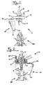
- FIG. 1 shows a schematic side view of a part assembly of the quick tool change system 1 as a first embodiment of the present invention.
- the tool quick-change system 1 comprises a torque arm 10, which via the housing of the torque arm 11 by means of a fastening device 16 and a driving device 18 with the machine tool connected is.
- the fastening device 16 is, with at least but not necessarily three attachment points, distributed around the axis of rotation along the X direction uniformly around the circumference and with a fixed radius to the center.
- the entrainment device 18 is fixed in part in the fastening device 16 and is another part of this fastening device, parallel to the X-axis and along the axis of rotation of the fastening device out.
- This driving device can be designed as a pin and is rotatably mounted in the machine tool to move the torque arm simultaneously with the tool head.
- the tool quick change system 1 further comprises a chip guide 20, which is rotatably connected to the torque arm 10. This connection is ensured via a support structure 26.
- the chip guiding device serves to dissipate the chips produced during the machining process and therefore comprises a chip guiding body 22. This encloses the machining zone, with the tool 30, in one piece.
- the chip deflector 22 can be divided into at least two areas. The first region is connected to the torque arm 10 by means of the support structure 26. This is flat, to ensure an exact contact surface between the support structure and chip deflector. A very accurate positioning is possible.
- the straight portion provides space for deriving the chips sufficiently far from the tool 30 after passing through a second arcuate portion. The tool 30 is thus not affected by loose parts.
- the second region of the chip guiding body 22 has a curved shape to guide the chips back towards the machine tool room. This can also be a concern for an existing suction device, since the chips are bundled better and more efficient extraction takes place.
- a cutout 24 has also been created in the lower part of the body. This detail is formally designed to be part of an arc curve.
- the unit which is decisive for the machining function within the tool quick-change system 1 is a tool interface 2.
- the interface represents in its shape a shaft, extends along the X axis and is enclosed by the torque arm 10.
- a receptacle for the machine tool 3. This can be performed at the customer's discretion and is machine tool dependent.
- the other, lower side of the shaft has an HSK adapter 4. This is in FIG. 1 exemplified as HSK-F63 tool holder. Fixing to a specific system is not absolutely necessary here and can be varied by the customer, depending on the tool 30.
- FIG. 2 shows an alternative embodiment of the tool interface 2. This differs primarily in that the tool holder at the bottom of the interface uses a different recording system.
- the tool interface in this embodiment has a mandrel 4 ', which receives the tool 30. The axial fixation of the tool takes over a screw which is screwed into a thread on the mandrel 4 '.
- the sectional drawing shows the connection between tool interface 2 and torque arm 10.
- This connection is designed so that between a bearing device 14 and the interface, a hollow shaft 13 is positioned, which allows easier replacement of the tool interface.
- the life of the bearing device 14 is also extended because the hollow shaft 13 is dimensionally designed so that a constant axial slippage of the inner bearing ring during installation and removal is avoided.
- the tool interface 2 is positioned and fixed by a fixing element 12.
- the fixing element can, as shown, by a shaft nut with wedge or by another mechanism. Possible here, for example, a bayonet lock or a bolt design that closes by means of compressed air.
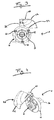
- FIG. 3 A tool quick change system 1 according to one of the two previous embodiments of the present invention is shown schematically in FIG. 3 shown in plan view. Good to see here is the previously described section 24 of the chips guide body 22. In addition, the positioning of the fastening device 16 and its distribution around the X-axis is clearly visible.
- FIG. 4 A complete overview of the tool quick change system 1 is the perspective FIG. 4 , There is the embodiment of FIG. 1 to see.
- the torque arm 10 together with the chip guiding device 20 can be mounted on the tool head of the machine tool.
- the tool interface 2 is ideally provided with a tool 30 prior to installation.
- the advantage is that a simple balancing process can take place by the previous assembly.
- the tool including the tool interface can be cleaned without damaging the bearing device.
- the tool interface 2 together with the tool 30 is then pushed from below, along the X-axis, into the hollow shaft 13 of the torque arm 10.
- the upper end of the interface 3 is positioned on the machine tool before the tool interface is pushed manually. By tightening or pressing the fixing element 12, the tool interface is pressed against the shaft shoulder of the hollow shaft 13 and thus forms a positive connection.
- the fixing element 12 tapers, through a wedge in the fixing element, the hollow shaft 13 and presses it onto the tool interface.
- the secure connection of the components ensures that the bearing device 14 at high speeds of the tool interface 2 works properly and without damage. It was found that this Connection has a positive effect on machining accuracy.
- preferably plate-shaped workpieces which are preferably at least partially made of wood, wood materials or plastic.
- the chip guide body 22 is automatically tracked in such a way that the chip guide body is always carried in the same position relative to the workpiece. This makes it possible to optimally adapt the chip deflector, without readjusting over the entire work process, to the chip flight and thus to steer the chips in a controlled direction.
- the tool interface 2 can also be operated without the torque support 10 and the chip guiding element 20.
Landscapes
- Engineering & Computer Science (AREA)
- Mechanical Engineering (AREA)
- Automatic Tool Replacement In Machine Tools (AREA)
Priority Applications (1)
| Application Number | Priority Date | Filing Date | Title |
|---|---|---|---|
| PL16167743T PL3090831T3 (pl) | 2015-05-06 | 2016-04-29 | Układ szybkiej wymiany narzędzi z urządzeniem do prowadzenia wiórów |
Applications Claiming Priority (1)
| Application Number | Priority Date | Filing Date | Title |
|---|---|---|---|
| DE202015003373.3U DE202015003373U1 (de) | 2015-05-06 | 2015-05-06 | Werkzeugschnellwechselsystem mit Späneleiteinrichtung |
Publications (2)
| Publication Number | Publication Date |
|---|---|
| EP3090831A1 true EP3090831A1 (fr) | 2016-11-09 |
| EP3090831B1 EP3090831B1 (fr) | 2022-01-26 |
Family
ID=54262109
Family Applications (1)
| Application Number | Title | Priority Date | Filing Date |
|---|---|---|---|
| EP16167743.0A Active EP3090831B1 (fr) | 2015-05-06 | 2016-04-29 | Système de changement rapide d'outil comprenant un dispositif de guidage de copeaux |
Country Status (3)
| Country | Link |
|---|---|
| EP (1) | EP3090831B1 (fr) |
| DE (1) | DE202015003373U1 (fr) |
| PL (1) | PL3090831T3 (fr) |
Cited By (1)
| Publication number | Priority date | Publication date | Assignee | Title |
|---|---|---|---|---|
| CN106976131A (zh) * | 2017-05-23 | 2017-07-25 | 慈溪智江机械科技有限公司 | 一种能自动切换钻头的板材打孔装置 |
Families Citing this family (2)
| Publication number | Priority date | Publication date | Assignee | Title |
|---|---|---|---|---|
| CN110709215B (zh) * | 2017-04-07 | 2023-08-01 | 睿信科机器人股份有限公司 | 用于工具适配器板的快速松脱机构和配置其的机器人 |
| IT201900018800A1 (it) * | 2019-10-15 | 2021-04-15 | Scm Group Spa | Dispositivo di schermatura di trucioli per un gruppo di lavorazione e macchina di lavorazione comprendente il dispositivo. |
Citations (11)
| Publication number | Priority date | Publication date | Assignee | Title |
|---|---|---|---|---|
| EP0407836A2 (fr) * | 1989-07-04 | 1991-01-16 | Mitsubishi Materials Corporation | Outil rotatif |
| DE4480343T1 (de) * | 1993-12-30 | 1997-03-27 | Horkos Corp | Für eine Werkzeugmaschine ausgelegte Vorrichtung zum Entfernen von Spänen |
| JPH10113839A (ja) * | 1996-10-14 | 1998-05-06 | Sumitomo Electric Ind Ltd | 切屑回収装置 |
| DE29907571U1 (de) | 1999-04-28 | 1999-07-29 | Homag Maschinenbau Ag, 72296 Schopfloch | Späneleiteinrichtung für ein Zerspanaggregat und Zerspanaggregat mit einer solchen Späneleiteinrichtung |
| EP0955125A2 (fr) * | 1998-05-07 | 1999-11-10 | Mitsubishi Materials Corporation | Outil de coupe |
| JP2002036056A (ja) * | 2000-07-21 | 2002-02-05 | Honda Motor Co Ltd | 切削加工装置 |
| DE10136996A1 (de) * | 2001-07-24 | 2003-02-20 | Mapal Fab Praezision | Werkzeug |
| DE60013853T2 (de) * | 1999-02-22 | 2005-09-22 | Horkos Corp., Fukuyama | Werkzeugmaschine mit spanabsaugeinrichtung |
| EP1985396A1 (fr) * | 2007-04-25 | 2008-10-29 | Homag Holzbearbeitungssysteme AG | Ensemble d'outils interchangeable |
| EP2251141A1 (fr) | 2009-05-16 | 2010-11-17 | Ledermann GmbH & Co. KG | Agencement de machine doté d'un capot d'aspiration |
| EP2420347A1 (fr) * | 2010-08-20 | 2012-02-22 | Homag Holzbearbeitungssysteme AG | Dispositif d'usinage avec tête inclinable |
-
2015
- 2015-05-06 DE DE202015003373.3U patent/DE202015003373U1/de not_active Expired - Lifetime
-
2016
- 2016-04-29 EP EP16167743.0A patent/EP3090831B1/fr active Active
- 2016-04-29 PL PL16167743T patent/PL3090831T3/pl unknown
Patent Citations (11)
| Publication number | Priority date | Publication date | Assignee | Title |
|---|---|---|---|---|
| EP0407836A2 (fr) * | 1989-07-04 | 1991-01-16 | Mitsubishi Materials Corporation | Outil rotatif |
| DE4480343T1 (de) * | 1993-12-30 | 1997-03-27 | Horkos Corp | Für eine Werkzeugmaschine ausgelegte Vorrichtung zum Entfernen von Spänen |
| JPH10113839A (ja) * | 1996-10-14 | 1998-05-06 | Sumitomo Electric Ind Ltd | 切屑回収装置 |
| EP0955125A2 (fr) * | 1998-05-07 | 1999-11-10 | Mitsubishi Materials Corporation | Outil de coupe |
| DE60013853T2 (de) * | 1999-02-22 | 2005-09-22 | Horkos Corp., Fukuyama | Werkzeugmaschine mit spanabsaugeinrichtung |
| DE29907571U1 (de) | 1999-04-28 | 1999-07-29 | Homag Maschinenbau Ag, 72296 Schopfloch | Späneleiteinrichtung für ein Zerspanaggregat und Zerspanaggregat mit einer solchen Späneleiteinrichtung |
| JP2002036056A (ja) * | 2000-07-21 | 2002-02-05 | Honda Motor Co Ltd | 切削加工装置 |
| DE10136996A1 (de) * | 2001-07-24 | 2003-02-20 | Mapal Fab Praezision | Werkzeug |
| EP1985396A1 (fr) * | 2007-04-25 | 2008-10-29 | Homag Holzbearbeitungssysteme AG | Ensemble d'outils interchangeable |
| EP2251141A1 (fr) | 2009-05-16 | 2010-11-17 | Ledermann GmbH & Co. KG | Agencement de machine doté d'un capot d'aspiration |
| EP2420347A1 (fr) * | 2010-08-20 | 2012-02-22 | Homag Holzbearbeitungssysteme AG | Dispositif d'usinage avec tête inclinable |
Cited By (1)
| Publication number | Priority date | Publication date | Assignee | Title |
|---|---|---|---|---|
| CN106976131A (zh) * | 2017-05-23 | 2017-07-25 | 慈溪智江机械科技有限公司 | 一种能自动切换钻头的板材打孔装置 |
Also Published As
| Publication number | Publication date |
|---|---|
| EP3090831B1 (fr) | 2022-01-26 |
| DE202015003373U1 (de) | 2015-09-23 |
| PL3090831T3 (pl) | 2022-04-04 |
Similar Documents
| Publication | Publication Date | Title |
|---|---|---|
| EP2915642B1 (fr) | Engin de construction | |
| EP3043946B1 (fr) | Dispositif d'alimentation en réfrigérant, machine de taillage en développante équipée de ce dispositif et procédé de taillage en développante au moyen de ce dispositif | |
| EP2551054B1 (fr) | Agencement destiné au ponçage d'électrodes | |
| EP2950955A1 (fr) | Logement pour un outil presentant une tige d'outil a filetage male | |
| DE102013107858B4 (de) | Werkzeug zum Dreh-Drehräumen von Werkstücken | |
| EP3090831A1 (fr) | Système de changement rapide d'outil comprenant un dispositif de guidage de copeaux | |
| DE102018003132B4 (de) | Werkzeugmaschine | |
| EP3819073A1 (fr) | Machine-outil | |
| EP2123379A1 (fr) | Fraiseuse et tour | |
| DE102018119980A1 (de) | Spann- oder Greifeinrichtung | |
| WO2018234193A1 (fr) | Broche de travail comprenant un dispositif de serrage radial | |
| EP0523574A2 (fr) | Dispositif de serrage pour outils singuliers | |
| EP2251141B1 (fr) | Agencement de machine doté d'un capot d'aspiration | |
| EP0328958B1 (fr) | Dispositif d'usinage de surfaces de pièces à symétrie de révolution | |
| DE102008046086B4 (de) | Schleifmaschine | |
| DE102019111843B4 (de) | Zerspanungswerkzeug | |
| DE102016116466B4 (de) | Spanleitdeckel für Schneidwerkzeug | |
| EP0758573B1 (fr) | Outil de meulage diamanté pour l'usinage de surface de pierre naturelle ou artificielle | |
| WO1998040189A1 (fr) | Dispositif d'alimentation en pieces d'une machine-outil | |
| DE102007038312A1 (de) | System zur Aufnahme von Bearbeitungsköpfen an einem Bearbeitungszentrum | |
| CH650714A5 (de) | Werkzeugwechselanordnung zum selbsttaetigen wechseln verschiedener arbeitseinsaetze. | |
| EP0123918B1 (fr) | Mandrin de fraisage et de serrage | |
| DE202007014828U1 (de) | Spannfutter für zu spannende Teile | |
| DE10320082B4 (de) | Baueinheit zur Bearbeitung von Holztafeln | |
| DE102006048495A1 (de) | Bearbeitungssystem zur spanenden Fertigbearbeitung von Pleuelaugen |
Legal Events
| Date | Code | Title | Description |
|---|---|---|---|
| PUAI | Public reference made under article 153(3) epc to a published international application that has entered the european phase |
Free format text: ORIGINAL CODE: 0009012 |
|
| AK | Designated contracting states |
Kind code of ref document: A1 Designated state(s): AL AT BE BG CH CY CZ DE DK EE ES FI FR GB GR HR HU IE IS IT LI LT LU LV MC MK MT NL NO PL PT RO RS SE SI SK SM TR |
|
| AX | Request for extension of the european patent |
Extension state: BA ME |
|
| STAA | Information on the status of an ep patent application or granted ep patent |
Free format text: STATUS: REQUEST FOR EXAMINATION WAS MADE |
|
| 17P | Request for examination filed |
Effective date: 20170418 |
|
| RBV | Designated contracting states (corrected) |
Designated state(s): AL AT BE BG CH CY CZ DE DK EE ES FI FR GB GR HR HU IE IS IT LI LT LU LV MC MK MT NL NO PL PT RO RS SE SI SK SM TR |
|
| STAA | Information on the status of an ep patent application or granted ep patent |
Free format text: STATUS: EXAMINATION IS IN PROGRESS |
|
| 17Q | First examination report despatched |
Effective date: 20170823 |
|
| GRAP | Despatch of communication of intention to grant a patent |
Free format text: ORIGINAL CODE: EPIDOSNIGR1 |
|
| STAA | Information on the status of an ep patent application or granted ep patent |
Free format text: STATUS: GRANT OF PATENT IS INTENDED |
|
| INTG | Intention to grant announced |
Effective date: 20210813 |
|
| GRAS | Grant fee paid |
Free format text: ORIGINAL CODE: EPIDOSNIGR3 |
|
| GRAA | (expected) grant |
Free format text: ORIGINAL CODE: 0009210 |
|
| STAA | Information on the status of an ep patent application or granted ep patent |
Free format text: STATUS: THE PATENT HAS BEEN GRANTED |
|
| AK | Designated contracting states |
Kind code of ref document: B1 Designated state(s): AL AT BE BG CH CY CZ DE DK EE ES FI FR GB GR HR HU IE IS IT LI LT LU LV MC MK MT NL NO PL PT RO RS SE SI SK SM TR |
|
| REG | Reference to a national code |
Ref country code: GB Ref legal event code: FG4D Free format text: NOT ENGLISH |
|
| REG | Reference to a national code |
Ref country code: CH Ref legal event code: EP |
|
| REG | Reference to a national code |
Ref country code: AT Ref legal event code: REF Ref document number: 1464884 Country of ref document: AT Kind code of ref document: T Effective date: 20220215 |
|
| REG | Reference to a national code |
Ref country code: IE Ref legal event code: FG4D Free format text: LANGUAGE OF EP DOCUMENT: GERMAN |
|
| REG | Reference to a national code |
Ref country code: DE Ref legal event code: R096 Ref document number: 502016014445 Country of ref document: DE |
|
| REG | Reference to a national code |
Ref country code: LT Ref legal event code: MG9D |
|
| REG | Reference to a national code |
Ref country code: NL Ref legal event code: MP Effective date: 20220126 |
|
| PG25 | Lapsed in a contracting state [announced via postgrant information from national office to epo] |
Ref country code: NL Free format text: LAPSE BECAUSE OF FAILURE TO SUBMIT A TRANSLATION OF THE DESCRIPTION OR TO PAY THE FEE WITHIN THE PRESCRIBED TIME-LIMIT Effective date: 20220126 |
|
| PG25 | Lapsed in a contracting state [announced via postgrant information from national office to epo] |
Ref country code: SE Free format text: LAPSE BECAUSE OF FAILURE TO SUBMIT A TRANSLATION OF THE DESCRIPTION OR TO PAY THE FEE WITHIN THE PRESCRIBED TIME-LIMIT Effective date: 20220126 Ref country code: RS Free format text: LAPSE BECAUSE OF FAILURE TO SUBMIT A TRANSLATION OF THE DESCRIPTION OR TO PAY THE FEE WITHIN THE PRESCRIBED TIME-LIMIT Effective date: 20220126 Ref country code: PT Free format text: LAPSE BECAUSE OF FAILURE TO SUBMIT A TRANSLATION OF THE DESCRIPTION OR TO PAY THE FEE WITHIN THE PRESCRIBED TIME-LIMIT Effective date: 20220526 Ref country code: NO Free format text: LAPSE BECAUSE OF FAILURE TO SUBMIT A TRANSLATION OF THE DESCRIPTION OR TO PAY THE FEE WITHIN THE PRESCRIBED TIME-LIMIT Effective date: 20220426 Ref country code: LT Free format text: LAPSE BECAUSE OF FAILURE TO SUBMIT A TRANSLATION OF THE DESCRIPTION OR TO PAY THE FEE WITHIN THE PRESCRIBED TIME-LIMIT Effective date: 20220126 Ref country code: HR Free format text: LAPSE BECAUSE OF FAILURE TO SUBMIT A TRANSLATION OF THE DESCRIPTION OR TO PAY THE FEE WITHIN THE PRESCRIBED TIME-LIMIT Effective date: 20220126 Ref country code: ES Free format text: LAPSE BECAUSE OF FAILURE TO SUBMIT A TRANSLATION OF THE DESCRIPTION OR TO PAY THE FEE WITHIN THE PRESCRIBED TIME-LIMIT Effective date: 20220126 Ref country code: BG Free format text: LAPSE BECAUSE OF FAILURE TO SUBMIT A TRANSLATION OF THE DESCRIPTION OR TO PAY THE FEE WITHIN THE PRESCRIBED TIME-LIMIT Effective date: 20220426 |
|
| PG25 | Lapsed in a contracting state [announced via postgrant information from national office to epo] |
Ref country code: LV Free format text: LAPSE BECAUSE OF FAILURE TO SUBMIT A TRANSLATION OF THE DESCRIPTION OR TO PAY THE FEE WITHIN THE PRESCRIBED TIME-LIMIT Effective date: 20220126 Ref country code: GR Free format text: LAPSE BECAUSE OF FAILURE TO SUBMIT A TRANSLATION OF THE DESCRIPTION OR TO PAY THE FEE WITHIN THE PRESCRIBED TIME-LIMIT Effective date: 20220427 Ref country code: FI Free format text: LAPSE BECAUSE OF FAILURE TO SUBMIT A TRANSLATION OF THE DESCRIPTION OR TO PAY THE FEE WITHIN THE PRESCRIBED TIME-LIMIT Effective date: 20220126 |
|
| PG25 | Lapsed in a contracting state [announced via postgrant information from national office to epo] |
Ref country code: IS Free format text: LAPSE BECAUSE OF FAILURE TO SUBMIT A TRANSLATION OF THE DESCRIPTION OR TO PAY THE FEE WITHIN THE PRESCRIBED TIME-LIMIT Effective date: 20220526 |
|
| REG | Reference to a national code |
Ref country code: DE Ref legal event code: R097 Ref document number: 502016014445 Country of ref document: DE |
|
| PG25 | Lapsed in a contracting state [announced via postgrant information from national office to epo] |
Ref country code: SM Free format text: LAPSE BECAUSE OF FAILURE TO SUBMIT A TRANSLATION OF THE DESCRIPTION OR TO PAY THE FEE WITHIN THE PRESCRIBED TIME-LIMIT Effective date: 20220126 Ref country code: SK Free format text: LAPSE BECAUSE OF FAILURE TO SUBMIT A TRANSLATION OF THE DESCRIPTION OR TO PAY THE FEE WITHIN THE PRESCRIBED TIME-LIMIT Effective date: 20220126 Ref country code: RO Free format text: LAPSE BECAUSE OF FAILURE TO SUBMIT A TRANSLATION OF THE DESCRIPTION OR TO PAY THE FEE WITHIN THE PRESCRIBED TIME-LIMIT Effective date: 20220126 Ref country code: EE Free format text: LAPSE BECAUSE OF FAILURE TO SUBMIT A TRANSLATION OF THE DESCRIPTION OR TO PAY THE FEE WITHIN THE PRESCRIBED TIME-LIMIT Effective date: 20220126 Ref country code: DK Free format text: LAPSE BECAUSE OF FAILURE TO SUBMIT A TRANSLATION OF THE DESCRIPTION OR TO PAY THE FEE WITHIN THE PRESCRIBED TIME-LIMIT Effective date: 20220126 Ref country code: CZ Free format text: LAPSE BECAUSE OF FAILURE TO SUBMIT A TRANSLATION OF THE DESCRIPTION OR TO PAY THE FEE WITHIN THE PRESCRIBED TIME-LIMIT Effective date: 20220126 |
|
| PG25 | Lapsed in a contracting state [announced via postgrant information from national office to epo] |
Ref country code: AL Free format text: LAPSE BECAUSE OF FAILURE TO SUBMIT A TRANSLATION OF THE DESCRIPTION OR TO PAY THE FEE WITHIN THE PRESCRIBED TIME-LIMIT Effective date: 20220126 |
|
| REG | Reference to a national code |
Ref country code: CH Ref legal event code: PL |
|
| PLBE | No opposition filed within time limit |
Free format text: ORIGINAL CODE: 0009261 |
|
| STAA | Information on the status of an ep patent application or granted ep patent |
Free format text: STATUS: NO OPPOSITION FILED WITHIN TIME LIMIT |
|
| GBPC | Gb: european patent ceased through non-payment of renewal fee |
Effective date: 20220429 |
|
| 26N | No opposition filed |
Effective date: 20221027 |
|
| REG | Reference to a national code |
Ref country code: BE Ref legal event code: MM Effective date: 20220430 |
|
| PG25 | Lapsed in a contracting state [announced via postgrant information from national office to epo] |
Ref country code: MC Free format text: LAPSE BECAUSE OF FAILURE TO SUBMIT A TRANSLATION OF THE DESCRIPTION OR TO PAY THE FEE WITHIN THE PRESCRIBED TIME-LIMIT Effective date: 20220126 Ref country code: LU Free format text: LAPSE BECAUSE OF NON-PAYMENT OF DUE FEES Effective date: 20220429 Ref country code: LI Free format text: LAPSE BECAUSE OF NON-PAYMENT OF DUE FEES Effective date: 20220430 Ref country code: GB Free format text: LAPSE BECAUSE OF NON-PAYMENT OF DUE FEES Effective date: 20220429 Ref country code: FR Free format text: LAPSE BECAUSE OF NON-PAYMENT OF DUE FEES Effective date: 20220430 Ref country code: CH Free format text: LAPSE BECAUSE OF NON-PAYMENT OF DUE FEES Effective date: 20220430 |
|
| PG25 | Lapsed in a contracting state [announced via postgrant information from national office to epo] |
Ref country code: SI Free format text: LAPSE BECAUSE OF FAILURE TO SUBMIT A TRANSLATION OF THE DESCRIPTION OR TO PAY THE FEE WITHIN THE PRESCRIBED TIME-LIMIT Effective date: 20220126 Ref country code: BE Free format text: LAPSE BECAUSE OF NON-PAYMENT OF DUE FEES Effective date: 20220430 |
|
| PG25 | Lapsed in a contracting state [announced via postgrant information from national office to epo] |
Ref country code: IE Free format text: LAPSE BECAUSE OF NON-PAYMENT OF DUE FEES Effective date: 20220429 |
|
| REG | Reference to a national code |
Ref country code: AT Ref legal event code: MM01 Ref document number: 1464884 Country of ref document: AT Kind code of ref document: T Effective date: 20220429 |
|
| P01 | Opt-out of the competence of the unified patent court (upc) registered |
Effective date: 20230529 |
|
| PG25 | Lapsed in a contracting state [announced via postgrant information from national office to epo] |
Ref country code: AT Free format text: LAPSE BECAUSE OF NON-PAYMENT OF DUE FEES Effective date: 20220429 |
|
| PG25 | Lapsed in a contracting state [announced via postgrant information from national office to epo] |
Ref country code: HU Free format text: LAPSE BECAUSE OF FAILURE TO SUBMIT A TRANSLATION OF THE DESCRIPTION OR TO PAY THE FEE WITHIN THE PRESCRIBED TIME-LIMIT; INVALID AB INITIO Effective date: 20160429 |
|
| PG25 | Lapsed in a contracting state [announced via postgrant information from national office to epo] |
Ref country code: MK Free format text: LAPSE BECAUSE OF FAILURE TO SUBMIT A TRANSLATION OF THE DESCRIPTION OR TO PAY THE FEE WITHIN THE PRESCRIBED TIME-LIMIT Effective date: 20220126 Ref country code: CY Free format text: LAPSE BECAUSE OF FAILURE TO SUBMIT A TRANSLATION OF THE DESCRIPTION OR TO PAY THE FEE WITHIN THE PRESCRIBED TIME-LIMIT Effective date: 20220126 |
|
| PG25 | Lapsed in a contracting state [announced via postgrant information from national office to epo] |
Ref country code: MT Free format text: LAPSE BECAUSE OF FAILURE TO SUBMIT A TRANSLATION OF THE DESCRIPTION OR TO PAY THE FEE WITHIN THE PRESCRIBED TIME-LIMIT Effective date: 20220126 |
|
| PGFP | Annual fee paid to national office [announced via postgrant information from national office to epo] |
Ref country code: PL Payment date: 20250403 Year of fee payment: 10 Ref country code: DE Payment date: 20250423 Year of fee payment: 10 |
|
| PGFP | Annual fee paid to national office [announced via postgrant information from national office to epo] |
Ref country code: IT Payment date: 20250428 Year of fee payment: 10 |
|
| PG25 | Lapsed in a contracting state [announced via postgrant information from national office to epo] |
Ref country code: TR Free format text: LAPSE BECAUSE OF FAILURE TO SUBMIT A TRANSLATION OF THE DESCRIPTION OR TO PAY THE FEE WITHIN THE PRESCRIBED TIME-LIMIT Effective date: 20220126 |