EP3090833A1 - Auf vereinheitlichten behälter basierendes trennsystem für schleifstrahlmaterial - Google Patents
Auf vereinheitlichten behälter basierendes trennsystem für schleifstrahlmaterial Download PDFInfo
- Publication number
- EP3090833A1 EP3090833A1 EP16168074.9A EP16168074A EP3090833A1 EP 3090833 A1 EP3090833 A1 EP 3090833A1 EP 16168074 A EP16168074 A EP 16168074A EP 3090833 A1 EP3090833 A1 EP 3090833A1
- Authority
- EP
- European Patent Office
- Prior art keywords
- air
- separation
- source
- separator
- blast
- Prior art date
- Legal status (The legal status is an assumption and is not a legal conclusion. Google has not performed a legal analysis and makes no representation as to the accuracy of the status listed.)
- Withdrawn
Links
- 238000000926 separation method Methods 0.000 title claims abstract description 42
- 239000000463 material Substances 0.000 title claims abstract description 41
- 238000005270 abrasive blasting Methods 0.000 title claims abstract description 18
- 239000000428 dust Substances 0.000 claims abstract description 33
- 238000011084 recovery Methods 0.000 claims abstract description 14
- 238000003860 storage Methods 0.000 claims abstract description 14
- 230000005291 magnetic effect Effects 0.000 claims abstract description 9
- 238000004891 communication Methods 0.000 claims description 18
- 238000012546 transfer Methods 0.000 claims description 15
- 238000004064 recycling Methods 0.000 claims description 9
- 238000009826 distribution Methods 0.000 claims description 6
- 238000010926 purge Methods 0.000 claims description 6
- 239000011435 rock Substances 0.000 claims description 6
- 230000000712 assembly Effects 0.000 claims description 4
- 238000000429 assembly Methods 0.000 claims description 4
- 239000002699 waste material Substances 0.000 claims description 4
- 238000002360 preparation method Methods 0.000 claims 1
- 230000003068 static effect Effects 0.000 claims 1
- 238000004140 cleaning Methods 0.000 abstract description 3
- 238000010586 diagram Methods 0.000 description 6
- 238000005422 blasting Methods 0.000 description 5
- 238000000034 method Methods 0.000 description 5
- 230000026676 system process Effects 0.000 description 5
- 230000007704 transition Effects 0.000 description 5
- 229910000831 Steel Inorganic materials 0.000 description 4
- 239000010959 steel Substances 0.000 description 4
- 230000005484 gravity Effects 0.000 description 3
- 239000006148 magnetic separator Substances 0.000 description 3
- 239000004576 sand Substances 0.000 description 3
- CWYNVVGOOAEACU-UHFFFAOYSA-N Fe2+ Chemical compound [Fe+2] CWYNVVGOOAEACU-UHFFFAOYSA-N 0.000 description 2
- 238000001914 filtration Methods 0.000 description 2
- 239000003973 paint Substances 0.000 description 2
- 239000002245 particle Substances 0.000 description 2
- 239000003082 abrasive agent Substances 0.000 description 1
- 238000009825 accumulation Methods 0.000 description 1
- 239000010425 asbestos Substances 0.000 description 1
- 238000005266 casting Methods 0.000 description 1
- 238000005516 engineering process Methods 0.000 description 1
- 239000004744 fabric Substances 0.000 description 1
- 230000005294 ferromagnetic effect Effects 0.000 description 1
- 231100001261 hazardous Toxicity 0.000 description 1
- JEIPFZHSYJVQDO-UHFFFAOYSA-N iron(III) oxide Inorganic materials O=[Fe]O[Fe]=O JEIPFZHSYJVQDO-UHFFFAOYSA-N 0.000 description 1
- 238000012423 maintenance Methods 0.000 description 1
- 238000012986 modification Methods 0.000 description 1
- 230000004048 modification Effects 0.000 description 1
- 229920000642 polymer Polymers 0.000 description 1
- 238000012545 processing Methods 0.000 description 1
- 239000002516 radical scavenger Substances 0.000 description 1
- 230000003134 recirculating effect Effects 0.000 description 1
- 229910052895 riebeckite Inorganic materials 0.000 description 1
- 238000012216 screening Methods 0.000 description 1
- 210000003462 vein Anatomy 0.000 description 1
Images




Classifications
-
- B—PERFORMING OPERATIONS; TRANSPORTING
- B24—GRINDING; POLISHING
- B24C—ABRASIVE OR RELATED BLASTING WITH PARTICULATE MATERIAL
- B24C9/00—Appurtenances of abrasive blasting machines or devices, e.g. working chambers, arrangements for handling used abrasive material
- B24C9/006—Treatment of used abrasive material
-
- B—PERFORMING OPERATIONS; TRANSPORTING
- B24—GRINDING; POLISHING
- B24C—ABRASIVE OR RELATED BLASTING WITH PARTICULATE MATERIAL
- B24C9/00—Appurtenances of abrasive blasting machines or devices, e.g. working chambers, arrangements for handling used abrasive material
-
- Y—GENERAL TAGGING OF NEW TECHNOLOGICAL DEVELOPMENTS; GENERAL TAGGING OF CROSS-SECTIONAL TECHNOLOGIES SPANNING OVER SEVERAL SECTIONS OF THE IPC; TECHNICAL SUBJECTS COVERED BY FORMER USPC CROSS-REFERENCE ART COLLECTIONS [XRACs] AND DIGESTS
- Y02—TECHNOLOGIES OR APPLICATIONS FOR MITIGATION OR ADAPTATION AGAINST CLIMATE CHANGE
- Y02P—CLIMATE CHANGE MITIGATION TECHNOLOGIES IN THE PRODUCTION OR PROCESSING OF GOODS
- Y02P70/00—Climate change mitigation technologies in the production process for final industrial or consumer products
- Y02P70/10—Greenhouse gas [GHG] capture, material saving, heat recovery or other energy efficient measures, e.g. motor control, characterised by manufacturing processes, e.g. for rolling metal or metal working
Definitions
- This invention relates to separation and recycling of abrasive steel blast material from entrained contaminates, including paint dust and rust encountered during the blasting process in cleaning and preparing a variety of surfaces in the industry.
- U.S. Patent 3,716,946 uses a recirculation close system with air separation as the initial separation with a secondary magnetic separator for removal of ferrous shot from the remaining non-ferrous contaminates.
- U.S. Patent 4,449,331 shows shot blasting machinery used in communication with a blast cabinet module.
- the device is characterized by a feed and lift conveyor recirculating system in communication with the blast cabinet for transportation of spent contaminated shot to the top of a vertical separation stack.
- U.S. Patent 3,934,374 a sand blast reclamation system is disclosed using an air wash separator feeding a blast wheel. Contaminated air is directed to a fabric dust collector for filtration. A sand separator is positioned above the magnetic separator supplying usable sand back to the blast wheel via an internal elevator belt.
- an abrasive blasting apparatus that provides for a movable self-contained blasting and separation unit that recovers the spent contaminated shot as it is used and recirculates same through a separation process.
- the separator uses an air driven grit reclaimer in combination with a transfer chamber.
- Patent 5,468,174 is directed to a recyclable abrasive blasting system having a classifier with auger screen separators and air wash.
- Patent 5,520,288 claims an abrasive grit material recovering system having a rotary screen separator, a magnetic separator, and an air wash on a mobile platform.
- Patent 5,695,385 shows a recyclable abrasive blasting system method using multiple auger screen separation and interconnected air wash to achieve particle separation.
- Applicant's Patent 6,514,128 discloses a separating abrasive blasting media from debris using a rotary drum separator with different size gradation interior surfaces.
- a containerized compact self-contained apparatus and system for separation of spent abrasive steel blast shot from entrained contaminates by use of multiple station material treatment Multiple equipment shipping container platforms are stacked for inter-working engagement, each containing multiple material processing equipment stations interlinked to one another by fixed material flow aligned fittings and multiple flexible product in-feed and outflow of contaminate separation and recovery of usable clean abrasive blast media in transitional storage for direct reuse on the work site.
- a compartmentalized transportable multiple container based separation apparatus 10 for separating and recovering of used steel blast shot material can be seen in figures 1 through 11 of the drawings.
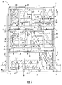
- the shippable container base separation apparatus 10 of the invention is assembled from self-contained shipping container-based modules 11, 12 and 13, each containing separation equipment arranged for interlinking dependency when stacked one upon another as seen in figures 7 , 8 and 10 of the drawings.
- Each of the equipment modules 11, 12 and 13 are configured to standard dimensions and interlocking frame element of an intermodal freight container universally used worldwide.
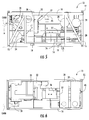
- each of the equipment modules 11, 12 and 13 having a rectangular base frame 14, each with multiple upstanding support posts 15 interconnected to a top rectangular support frame 16, as best seen in figures 1 through 6 of the drawings.
- Each of the corner support posts 15 have an inter-engageable end fitting 17 of a universal intermodal freight container, best seen in figure 9 of the drawings.
- the end fittings 17 can therefore be secured to one another for vertical stacking by an internal twist-lock corner casting assembly 18 in which a male moveable twist-lock is inserted into a female opening in the adjacent container fitting to be engaged and secured together by rotation therewithin, as will be well understood by those skilled in the container art.
- Each of the base frames 14 have parallel rails 14A and 14B with a corresponding space pair of forklift engagement openings 19 therein for lifting and placement, again as will be well understood by and known within the container art.
- the top (first) equipment module 13 can be seen independently in an un-stacked orientation.
- the equipment module 13 has initial large debris (rocks) cylindrical screen drop out intake box 20 with a vacuum transfer inlet 21 for contaminated abrasive blast material CABM from the work site WS.
- the drop box 20 screens out and separates large debris while pulling off lighter dust and contaminates through a high vacuum outflow port at 22 which is transferred down to the second or middle equipment module 12, as will be discussed in greater detail hereinafter.
- a double dump airlock assembly 24 has two compartmentalized dump valves 24A and 24B that selectively transfer accumulated contaminated blast shot, releasing directly into a magnetic drum separator 25 within the equipment module 12 positioned there below.
- the magnetic drum inlet transition connection is achieved therebetween by a rubber sleeve assembly 26 as seen in figure 10 of the drawings.
- a large electric motor 26 is mounted adjacent to the double dump valve assembly 24 with a control panel P for a source of electrical power thereto.
- the motor 26 drives a large air vacuum pump 27 in communication with associated intake and exhaust silencers 28 and 29 and a final outflow filter 30, typically required in large vacuum system applications.
- the second equipment module 12 can be seen containing hereinbefore referred to magnetic drum separator 25 that receives the contaminated shot blast and provides for selective particle engagement and magnetic attraction of contaminates, as is well known and established within the art.
- the separated debris exits at 25A seen graphically in figure 12 of the drawings.
- the remaining magnetically separated material SM is deposited directly onto a vibrating screen separator classifier 31 that will selectively sort and classify by screen designated size openings for screen selection.
- Screened contents that exit at 31A are transferred to (waste) as designated large debris, while small contaminates 31 B pass through screening trays S2 into a collection transfer guide at 31 C, as will be well understood by those within the vibrating screen technology art used commercially within the industry.
- a multi-stage the air washer 33 then receives the screened abrasive shot blast material SASBM and remaining entrained related contaminates (dust) 33B.
- the air washer 33 has a vertical chamber 34 having multiple angularly positioned veins 34A, each of which is adjacent to corresponding outside air inlet 34B so as to affect a specific gravity air separation of the contaminated abrasive blast material as it cascades downwardly therethrough by gravity, seen graphically in figure 12 of the drawings.
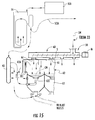
- the air wash effectively separates entrained lighter weight contaminates C including dust, forcing same upwardly through a return and removable passage way 34C to be drawn off by a vacuum dust control system, comprising a low vac fan blower indicated at 35 connected by a transfer hose TH to an outlet 36 of a low vac cartridge bag based dust filter assembly 37 seen in figures 3 and 4 and graphically in figure 14 of the drawings.
- the low vac dust filter bag base assembly 37 has a first contaminate material inlet at 37A with a plurality of dust collector filter bag cartridges 38 within, with maintenance access and oppositely disposed lower chamber clean-out valve 39.
- a flexible dust transfer hose 40 extends from the clean-out valve 39 and fitting 39A down to a collection container 41 once the multiple equipment modules 11, 12 and 13 are stacked and fully connected to one another as will be described in greater detail hereinafter.
- the low vac cartridge bag based dust filter assembly 37 has a compressed air filter purged multiple nozzle assembly 42 positioned above the hereinbefore described multiple dust filter bag cartridges 38 and is in communication with a source of compressed air SCA via a distribution manifold 43 providing for bag filter cleaning as required, illustrated in figure 15 of the drawings.
- a cyclonic separator 44 within the equipment module 12 can be seen in communication with the outflow port 22 of the cylinder deposit drop box 20 described via a fixed and flexible transfer conduit piping 45 best seen in figure 7 of the drawings.
- the cyclonic air separator 44 pulls off the lighter contaminates in a cyclonic air stream allowing the remaining material to drop and accumulate within a storage area 44A.
- the lighter entrained contaminated air flow CAF is pulled into a high vacuum dust control system 45 consisting of the vacuum pump 27 having a three lobed air injector high vac blower 46 to supply vacuum circulation through a high vacuum dust filter and dust cartridge bag filtration house 47 via a vacuum transition piping assembly 48, best seen in figure 11 of the drawings.
- the transition piping assembly 48 has a pair of aligned transitioned tubes 48A and 48B interconnected together by a first rubber sleeve fitting 49.
- Oppositely disposed secondary and third rubber sleeve fittings 49A and 49B connect the respective transition tubes 48A and 48B to a high vacuum outlet pipe fitting 50 and a final filter inlet pipe 51 on the final filter 30 in the first equipment module 13 in direct communication with the high vac blower 46.
- the high vac dust cartridge bag filter house 47 has a plurality of dust collector filter bag cartridges 53, best seen graphically in figure 13 of the drawings.
- An air purge nozzle assembly 54 is positioned within the high vac dust filter bag cartridge house 47 above respective filter bag cartridges 53 and is in communication with a source of compressed air SCA manifold 55 and a remote air source via a compressed air system inlets 56, best seen in figure 7 of the drawing, extending from the base of the third equipment module 11.
- Compressed air manifold also supplies a purge nozzle assembly 54 in the low vacuum bag house 37.
- the high vacuum dust filter cartridge bag filter house 47 has a top access panel 47A and a lower chamber clean-out valve 47B.
- the now cleaned and reusable shot blast material indicated in broken line arrows CM exit the air wash 33 directly into a transfer distribution screw auger 60, which conveys the shot blast material CM to multiple inlet fittings 61 of a grit storage bin portion 62 in the equipment module 11 on the ground G.
- a transfer distribution screw auger 60 conveys the shot blast material CM to multiple inlet fittings 61 of a grit storage bin portion 62 in the equipment module 11 on the ground G.
- the bin to auger connections were achieved during the modular stacking assembly, using in this instance a plurality of rubber sleeves S installed on respective auger discharge pipes 60A, 60B, 60C and 60D.
- the grit storage bin 62 portion has a plurality of integral shot blast supply pots 63.
- the clean blast shot CM is initially held as noted in the upper portion 62A separated by a contoured bottom 62B with a remotely operated material release valve 62C for releasing the material therefrom into the lower blast pot portions 63 ready for reuse, as will be described hereinafter.
- the intermodal equipment modules 11, 12 and 13 can be easily transported independently to their intended work site destination given their uniform "shipping container" configurations.
- the equipment modules 11, 12 and 13 are prepared for vertical integrated stacking by installing a multiple interconnecting resilient sleeve S and fixed connector elements between the equipment modules, including the auger outlets 60A, 60B, 60C, and 60D and blast shot storage bins 62, along with the connection from the double dump valve assembly 24 of the rock box 20 with the magnetic drum 25 in-feed.
- multiple flexible sleeve and fitting assemblies 48 is positioned for connection between the final air filter 30 and the high vac filter housing 47 and the flexible hose 45 and sleeve fittings between the air outflow and rock box 20 and cyclonic separator 44, as hereinbefore described.
- a stacking and alignment and orientation is achieved by color coding one corner support post 15A on each of the modules, so that the colored post matching assures proper alignment.
- the equipment modules 11, 12 and 13 are selective locked to one another by the respective post twist-lock fitting 17.
- An exterior vacuum inlet hose 68 extends up the equipment stack and is in communication with the rock box vacuum inlet 21 and the work site WS to initiate the collection and transfer of the used contaminated shot blast entrained with a variety of contaminates to begin the separation process of the compartmentalized transportable multiple intermodal container modules base system of the invention.
Landscapes
- Engineering & Computer Science (AREA)
- Mechanical Engineering (AREA)
- Filtering Of Dispersed Particles In Gases (AREA)
- Combined Means For Separation Of Solids (AREA)
- Cyclones (AREA)
Applications Claiming Priority (1)
| Application Number | Priority Date | Filing Date | Title |
|---|---|---|---|
| US14/702,981 US10092996B2 (en) | 2015-05-04 | 2015-05-04 | Unitized container based abrasive blasting material separation system |
Publications (1)
| Publication Number | Publication Date |
|---|---|
| EP3090833A1 true EP3090833A1 (de) | 2016-11-09 |
Family
ID=55967062
Family Applications (1)
| Application Number | Title | Priority Date | Filing Date |
|---|---|---|---|
| EP16168074.9A Withdrawn EP3090833A1 (de) | 2015-05-04 | 2016-05-03 | Auf vereinheitlichten behälter basierendes trennsystem für schleifstrahlmaterial |
Country Status (2)
| Country | Link |
|---|---|
| US (1) | US10092996B2 (de) |
| EP (1) | EP3090833A1 (de) |
Cited By (2)
| Publication number | Priority date | Publication date | Assignee | Title |
|---|---|---|---|---|
| CN114571374A (zh) * | 2022-03-14 | 2022-06-03 | 陕西捷特智能科技有限公司 | 基于涡流磁导向射流3d复杂零件内流道清理装置及方法 |
| RU2841401C1 (ru) * | 2024-09-25 | 2025-06-06 | Общество с ограниченной ответственностью "ПРОЕКТТОРГЭКСПЕРТ" | Устройство для сбора, регенерации и временного хранения абразивной среды при открытой дробеструйной обработке |
Families Citing this family (4)
| Publication number | Priority date | Publication date | Assignee | Title |
|---|---|---|---|---|
| EP2697552B1 (de) * | 2011-04-13 | 2016-01-13 | Dresser-Rand Company | Kompakter verpackungsentwurf für ein kompressionssystem |
| US11440162B2 (en) | 2018-10-03 | 2022-09-13 | Blastec, Inc. | Apparatus and method for separating reusable abrasive media from non-reusable media |
| FR3101005B1 (fr) * | 2019-09-25 | 2021-08-20 | Alter Ego | Procédé de traitement de fûts en bois à l’aide d’un abrasif à base de grenaille et dispositif de traitement pour sa mise en œuvre |
| CN112605898A (zh) * | 2021-01-15 | 2021-04-06 | 成都市新都区门办开商贸有限公司 | 一种水下船体喷砂除锈并回收磨料设备 |
Citations (19)
| Publication number | Priority date | Publication date | Assignee | Title |
|---|---|---|---|---|
| US2810991A (en) | 1955-02-18 | 1957-10-29 | William H Mead | Abrasive blasting apparatus |
| US2935820A (en) * | 1957-10-22 | 1960-05-10 | William H Mead | Air-solids separation system for blast room |
| US3716946A (en) | 1969-12-11 | 1973-02-20 | Badische Maschf Gmbh | Method and apparatus for cleaning and recuperating shot in the circulatory system of blasting apparatus |
| US3716941A (en) | 1971-05-05 | 1973-02-20 | R Dowden | Apparatus for use by a rodeo performer for practicing tying the legs of a calf |
| US3934374A (en) | 1974-08-21 | 1976-01-27 | Wheelabrator-Frye, Inc. | Sand reclamation system |
| US3954374A (en) | 1971-05-14 | 1976-05-04 | Maschinenfabrik Rissen G.M.B.H. | Device for the manufacture of deep-drawn objects using synthetic, thermoplastic foils |
| US4449331A (en) | 1981-03-17 | 1984-05-22 | Tiglhman Wheelabrator Limited | Shot blasting machinery |
| US4773189A (en) | 1985-11-01 | 1988-09-27 | Macmillan Gregory D | Separation system for polymeric blast media |
| US4943368A (en) | 1988-11-15 | 1990-07-24 | Pittsburgh Mineral & Environmental Technology, Inc. | Nonmetallic abrasive blasting material recovery process including an electrostatic separation step |
| US5185986A (en) | 1990-10-26 | 1993-02-16 | Pfizer, Inc. | Bail applicator and method |
| US5185968A (en) | 1991-06-26 | 1993-02-16 | Corcon (Ohio Corporation) | Mobile separation sytem for abrasive blasting material |
| US5212911A (en) * | 1991-05-29 | 1993-05-25 | Benson Ronald C | Abrasive particle blasting device and method |
| US5269424A (en) * | 1991-06-26 | 1993-12-14 | Corcon | Mobile separation method system for abrasive blasting material |
| US5468147A (en) | 1994-07-21 | 1995-11-21 | Yao; Stephen C. | Orthodontic wire |
| US5468174A (en) | 1992-11-13 | 1995-11-21 | Ipec Advanced Systems, Inc. | Recyclable abrasive blasting system |
| US5520288A (en) | 1994-03-21 | 1996-05-28 | Pct, Inc. | Abrasive grit material recovery system |
| US6514128B1 (en) | 2002-07-09 | 2003-02-04 | Gus Lyras | Apparatus for separating abrasive blasting media from debris |
| US20130157545A1 (en) * | 2011-09-06 | 2013-06-20 | John Russell RODEN | Apparatus and method for providing a modular abrasive blasting and recovery system |
| US8771040B1 (en) * | 2011-08-10 | 2014-07-08 | Gus Lyras | Mobile abrasive blasting material separation device and method |
Family Cites Families (5)
| Publication number | Priority date | Publication date | Assignee | Title |
|---|---|---|---|---|
| US5035089A (en) * | 1990-01-29 | 1991-07-30 | Pauli & Griffin | Blast media recovery and cleaning system |
| US5882381A (en) * | 1996-03-28 | 1999-03-16 | Modern Equipment Company, Inc. | Thermal desorption system |
| US6186273B1 (en) * | 1997-02-19 | 2001-02-13 | Metro Machine Corporation | Self-contained staging system for cleaning and painting bulk cargo holds |
| US6102157A (en) * | 1997-02-19 | 2000-08-15 | Metro Machine Corporation | Self-contained staging system for cleaning and painting bulk cargo holds |
| WO2012148430A1 (en) * | 2011-04-28 | 2012-11-01 | Reco Atlantic Llc | Apparatus and method for reclaiming abrasive blasting material and screening device for separating abrasive blasting material |
-
2015
- 2015-05-04 US US14/702,981 patent/US10092996B2/en active Active
-
2016
- 2016-05-03 EP EP16168074.9A patent/EP3090833A1/de not_active Withdrawn
Patent Citations (20)
| Publication number | Priority date | Publication date | Assignee | Title |
|---|---|---|---|---|
| US2810991A (en) | 1955-02-18 | 1957-10-29 | William H Mead | Abrasive blasting apparatus |
| US2935820A (en) * | 1957-10-22 | 1960-05-10 | William H Mead | Air-solids separation system for blast room |
| US3716946A (en) | 1969-12-11 | 1973-02-20 | Badische Maschf Gmbh | Method and apparatus for cleaning and recuperating shot in the circulatory system of blasting apparatus |
| US3716941A (en) | 1971-05-05 | 1973-02-20 | R Dowden | Apparatus for use by a rodeo performer for practicing tying the legs of a calf |
| US3954374A (en) | 1971-05-14 | 1976-05-04 | Maschinenfabrik Rissen G.M.B.H. | Device for the manufacture of deep-drawn objects using synthetic, thermoplastic foils |
| US3934374A (en) | 1974-08-21 | 1976-01-27 | Wheelabrator-Frye, Inc. | Sand reclamation system |
| US4449331A (en) | 1981-03-17 | 1984-05-22 | Tiglhman Wheelabrator Limited | Shot blasting machinery |
| US4773189A (en) | 1985-11-01 | 1988-09-27 | Macmillan Gregory D | Separation system for polymeric blast media |
| US4943368A (en) | 1988-11-15 | 1990-07-24 | Pittsburgh Mineral & Environmental Technology, Inc. | Nonmetallic abrasive blasting material recovery process including an electrostatic separation step |
| US5185986A (en) | 1990-10-26 | 1993-02-16 | Pfizer, Inc. | Bail applicator and method |
| US5212911A (en) * | 1991-05-29 | 1993-05-25 | Benson Ronald C | Abrasive particle blasting device and method |
| US5185968A (en) | 1991-06-26 | 1993-02-16 | Corcon (Ohio Corporation) | Mobile separation sytem for abrasive blasting material |
| US5269424A (en) * | 1991-06-26 | 1993-12-14 | Corcon | Mobile separation method system for abrasive blasting material |
| US5468174A (en) | 1992-11-13 | 1995-11-21 | Ipec Advanced Systems, Inc. | Recyclable abrasive blasting system |
| US5695385A (en) | 1992-11-13 | 1997-12-09 | Ipec, Llc | Recyclable abrasive blasting system and method |
| US5520288A (en) | 1994-03-21 | 1996-05-28 | Pct, Inc. | Abrasive grit material recovery system |
| US5468147A (en) | 1994-07-21 | 1995-11-21 | Yao; Stephen C. | Orthodontic wire |
| US6514128B1 (en) | 2002-07-09 | 2003-02-04 | Gus Lyras | Apparatus for separating abrasive blasting media from debris |
| US8771040B1 (en) * | 2011-08-10 | 2014-07-08 | Gus Lyras | Mobile abrasive blasting material separation device and method |
| US20130157545A1 (en) * | 2011-09-06 | 2013-06-20 | John Russell RODEN | Apparatus and method for providing a modular abrasive blasting and recovery system |
Cited By (2)
| Publication number | Priority date | Publication date | Assignee | Title |
|---|---|---|---|---|
| CN114571374A (zh) * | 2022-03-14 | 2022-06-03 | 陕西捷特智能科技有限公司 | 基于涡流磁导向射流3d复杂零件内流道清理装置及方法 |
| RU2841401C1 (ru) * | 2024-09-25 | 2025-06-06 | Общество с ограниченной ответственностью "ПРОЕКТТОРГЭКСПЕРТ" | Устройство для сбора, регенерации и временного хранения абразивной среды при открытой дробеструйной обработке |
Also Published As
| Publication number | Publication date |
|---|---|
| US20160325403A1 (en) | 2016-11-10 |
| US10092996B2 (en) | 2018-10-09 |
Similar Documents
| Publication | Publication Date | Title |
|---|---|---|
| US9022835B1 (en) | Mobile abrasive blasting material separation device and method | |
| US10092996B2 (en) | Unitized container based abrasive blasting material separation system | |
| US10457501B2 (en) | Systems and methods for converter bed unloading and loading | |
| US8771040B1 (en) | Mobile abrasive blasting material separation device and method | |
| CA2086275C (en) | Mobile separation system for abrasive blasting material | |
| US10399881B2 (en) | Methods and systems for separating solid particulates from waste water | |
| US5185968A (en) | Mobile separation sytem for abrasive blasting material | |
| WO2001019529A2 (en) | Quick color change powder coating system | |
| US9434049B2 (en) | Apparatus and method for providing a modular abrasive blasting and recovery system | |
| TW201328793A (zh) | 粉粒體分離處理裝置及粉粒體分離處理方法以及粉粒體分離回收處理系統 | |
| US20170291779A1 (en) | Dust control in pneumatic particulate handling applications | |
| US10675724B2 (en) | Swarf and lubricant recovery system | |
| US4889452A (en) | Vented product pump and air filter arrangement | |
| US10543581B2 (en) | Multi-stage grit recycler | |
| US6514128B1 (en) | Apparatus for separating abrasive blasting media from debris | |
| US9707594B2 (en) | Lead and rubber reclamation apparatus and process | |
| US20240359121A1 (en) | Dual inlet cyclonic separation apparatus for processing flowback from wellsite | |
| CN217491709U (zh) | 一种干式磁选设备 | |
| WO2004007053A2 (en) | Device for the filtration and collection of microparticles in a gaseous environment | |
| KR102135532B1 (ko) | 작업효율이 향상된 원료 덩어리 분리가 가능한 미분원료 공급장치 | |
| TWI472468B (zh) | 微細粉體氣力輸送裝置 | |
| KR101209528B1 (ko) | 분체 도료 분리장치 | |
| WO2022106706A1 (en) | Material sorting apparatus | |
| JP2004101336A (ja) | 放射性廃棄物の分別回収システムおよび分別装置 |
Legal Events
| Date | Code | Title | Description |
|---|---|---|---|
| PUAI | Public reference made under article 153(3) epc to a published international application that has entered the european phase |
Free format text: ORIGINAL CODE: 0009012 |
|
| AK | Designated contracting states |
Kind code of ref document: A1 Designated state(s): AL AT BE BG CH CY CZ DE DK EE ES FI FR GB GR HR HU IE IS IT LI LT LU LV MC MK MT NL NO PL PT RO RS SE SI SK SM TR |
|
| AX | Request for extension of the european patent |
Extension state: BA ME |
|
| 17P | Request for examination filed |
Effective date: 20170502 |
|
| RBV | Designated contracting states (corrected) |
Designated state(s): AL AT BE BG CH CY CZ DE DK EE ES FI FR GB GR HR HU IE IS IT LI LT LU LV MC MK MT NL NO PL PT RO RS SE SI SK SM TR |
|
| STAA | Information on the status of an ep patent application or granted ep patent |
Free format text: STATUS: REQUEST FOR EXAMINATION WAS MADE |
|
| STAA | Information on the status of an ep patent application or granted ep patent |
Free format text: STATUS: EXAMINATION IS IN PROGRESS |
|
| 17Q | First examination report despatched |
Effective date: 20180411 |
|
| GRAP | Despatch of communication of intention to grant a patent |
Free format text: ORIGINAL CODE: EPIDOSNIGR1 |
|
| STAA | Information on the status of an ep patent application or granted ep patent |
Free format text: STATUS: GRANT OF PATENT IS INTENDED |
|
| INTG | Intention to grant announced |
Effective date: 20181212 |
|
| STAA | Information on the status of an ep patent application or granted ep patent |
Free format text: STATUS: THE APPLICATION IS DEEMED TO BE WITHDRAWN |
|
| 18D | Application deemed to be withdrawn |
Effective date: 20190424 |