EP3090836A1 - Outil pour enfoncer des organes de fixation à dispositif de sécurité amélioré - Google Patents
Outil pour enfoncer des organes de fixation à dispositif de sécurité amélioré Download PDFInfo
- Publication number
- EP3090836A1 EP3090836A1 EP15166582.5A EP15166582A EP3090836A1 EP 3090836 A1 EP3090836 A1 EP 3090836A1 EP 15166582 A EP15166582 A EP 15166582A EP 3090836 A1 EP3090836 A1 EP 3090836A1
- Authority
- EP
- European Patent Office
- Prior art keywords
- tool
- trigger
- connection
- standby
- state
- Prior art date
- Legal status (The legal status is an assumption and is not a legal conclusion. Google has not performed a legal analysis and makes no representation as to the accuracy of the status listed.)
- Withdrawn
Links
- 230000004913 activation Effects 0.000 claims abstract description 127
- 238000000034 method Methods 0.000 claims abstract description 21
- 238000012546 transfer Methods 0.000 claims abstract description 17
- 230000003213 activating effect Effects 0.000 claims description 17
- 230000001960 triggered effect Effects 0.000 claims description 8
- 238000006073 displacement reaction Methods 0.000 claims description 6
- 230000000694 effects Effects 0.000 claims description 3
- 238000007599 discharging Methods 0.000 abstract description 7
- 238000007789 sealing Methods 0.000 description 19
- 208000020401 Depressive disease Diseases 0.000 description 12
- 238000013461 design Methods 0.000 description 9
- 230000008878 coupling Effects 0.000 description 8
- 238000010168 coupling process Methods 0.000 description 8
- 238000005859 coupling reaction Methods 0.000 description 8
- 238000009423 ventilation Methods 0.000 description 6
- 230000008569 process Effects 0.000 description 5
- 230000008859 change Effects 0.000 description 4
- TZCXTZWJZNENPQ-UHFFFAOYSA-L barium sulfate Chemical compound [Ba+2].[O-]S([O-])(=O)=O TZCXTZWJZNENPQ-UHFFFAOYSA-L 0.000 description 3
- 230000003042 antagnostic effect Effects 0.000 description 2
- 230000000903 blocking effect Effects 0.000 description 2
- 238000010586 diagram Methods 0.000 description 2
- 230000000284 resting effect Effects 0.000 description 2
- 238000013022 venting Methods 0.000 description 2
- 150000001875 compounds Chemical class 0.000 description 1
- 239000004567 concrete Substances 0.000 description 1
- 238000010276 construction Methods 0.000 description 1
- 230000007423 decrease Effects 0.000 description 1
- 230000001419 dependent effect Effects 0.000 description 1
- 230000000994 depressogenic effect Effects 0.000 description 1
- 238000011161 development Methods 0.000 description 1
- 230000018109 developmental process Effects 0.000 description 1
- 230000009977 dual effect Effects 0.000 description 1
- 239000012530 fluid Substances 0.000 description 1
- 230000006266 hibernation Effects 0.000 description 1
- 238000002347 injection Methods 0.000 description 1
- 239000007924 injection Substances 0.000 description 1
- 230000007257 malfunction Effects 0.000 description 1
- 239000002184 metal Substances 0.000 description 1
- 239000003380 propellant Substances 0.000 description 1
- 239000007787 solid Substances 0.000 description 1
- 239000002023 wood Substances 0.000 description 1
Images


Classifications
-
- B—PERFORMING OPERATIONS; TRANSPORTING
- B25—HAND TOOLS; PORTABLE POWER-DRIVEN TOOLS; MANIPULATORS
- B25C—HAND-HELD NAILING OR STAPLING TOOLS; MANUALLY OPERATED PORTABLE STAPLING TOOLS
- B25C1/00—Hand-held nailing tools; Nail feeding devices
- B25C1/008—Safety devices
-
- B—PERFORMING OPERATIONS; TRANSPORTING
- B25—HAND TOOLS; PORTABLE POWER-DRIVEN TOOLS; MANIPULATORS
- B25C—HAND-HELD NAILING OR STAPLING TOOLS; MANUALLY OPERATED PORTABLE STAPLING TOOLS
- B25C1/00—Hand-held nailing tools; Nail feeding devices
- B25C1/04—Hand-held nailing tools; Nail feeding devices operated by fluid pressure, e.g. by air pressure
- B25C1/047—Mechanical details
Definitions
- the invention relates to a driving tool for driving fasteners into a workpiece by means of driving cycles, in which a securing device is intended to prevent unintentional triggering when the trigger is actuated after a predetermined time.
- a generic driving tool is in valuable contribution to the prior art DE 10 2013 106 657 A1 shown.
- Eintreibwerkmaschine a safety device, referred to therein as a reset arrangement, activated by a first Eintreibzyklus, which is performed in the so-called single trip operation there.
- the safety device transfers the tool to a safe state after a predetermined delay time, provided that the trigger remains depressed and if no drive-in cycle takes place within the delay time.
- the EP 2 767 365 A1 relates to a pneumatic nailer, which has, inter alia, a second control valve which is actuated upon actuation of the trigger independently of actuation of the Aufsetzfactlers, a chamber which is either vented or vented via a throttle when driving the second control valve, and a locking piston, the is displaced from a rest position to a blocking position when the pressure in the chamber passes a predetermined pressure threshold, and prevents the triggering of a driving operation in the blocking position.
- Object of the present invention was to improve the disadvantages of the prior art, in particular to increase the flexibility of the tool use and to ensure a comparable security.
- the flexibility of the tool use is increased, since the securing device can be activated independently of the state of the workpiece contact element and thus not first a first single trip operation-driving cycle must be made to activate the safety device for the first time. From the beginning, the user can operate the tool in individual trip mode or in contact tripping mode. At the same time a comparable security is obtained since the safety device still transfers the tool to a secured state after a predetermined delay time, so that even if the user inadvertently presses the trigger element before triggering a first drive-in cycle, an unintentional triggering of a drive-in cycle only occurs within the predetermined delay time is possible, but not otherwise.
- the tool has an activation element, by means of which an activation of the securing device is coupled to the trigger movement, in that the displacement of the activation element by the trigger element is used when the trigger element is pressed to cause an activation of the safety device.
- Fasteners include nails, pins or special retractable screws.
- a workpiece for example, wood, metal or concrete into consideration.
- the actuator unit is preferably a pneumatic actuator unit, in which the force required for driving force is provided purely from pneumatic energy.
- the actuator unit preferably has a working piston guided in a working cylinder.
- the actuator unit preferably has a main triggering valve, preferably a check valve, by means of which the working cylinder can be suddenly filled with compressed air, so that the driving piston is moved in the direction of the tool tip.
- the working piston is preferably connected to a Eintreibstkov which acts on the Conspande fastener.
- a drive-in cycle is a recurring process that the actuator unit performs to sequentially drive fasteners.
- the triggering arrangement preferably has a triggering valve which is coupled purely mechanically via solids (without fluid) to the trigger element.
- the trigger valve is preferably accommodated in a trigger valve housing, which is separate from the housing of the tool and thus is easily replaceable or retrofittable.
- the activation element is received in the trigger valve housing.
- the activation element is preferably part of the triggering valve.
- the control volume is preferably an interior of the tool, which is set up for the temporary storage of pneumatic energy. It is preferably arranged directly on the working cylinder of the tool, which includes the working piston, adjacent in the tool. Preferably, it surrounds the lateral surface of the working cylinder at least in a region completely by 360 °. Preferably, the tool has a venting arrangement (e.g., openings in the working cylinder) by means of which the control volume can be filled with compressed air during a driving operation.
- a venting arrangement e.g., openings in the working cylinder
- the trigger element may e.g. be pivotable or linearly slidable, e.g. a lever or button. It is preferably biased by a spring in the resting state.
- the trigger element is set up (also) to activate the safety device by a change from its idle state to the depressed state when the workpiece contact element is unactuated.
- One of the first and the second position of the activation element is preferably an activation position for activating the safety device, ie that a Changing the activation element from the other position into the activation position can start the expiration of a delay time, before then the safety device transfers the tool in the secured state.
- the activation element is preferably in the activation position when the trigger element is in the depressed state.
- the pneumatic connection of charging connection and discharge connection which is provided by means of the activation element in the activation position, the compound having the smallest flow cross-section, which determines the delay time together with the gas pressure of the gas pressure source.
- This connection is preferably the discharge connection, ie via which air flows from the control volume to the pressure sink.
- the discharge connection extends through one, preferably two (preferably in a lateral surface of an activation element designed as a pipe piece) openings of the activation element.
- this opening forms a smallest flow cross-section, which defines the predetermined delay time together with the gas pressure.
- a setting needle is arranged in this opening, which is preferably tapered and thus the flow cross-section of the opening can be changed by moving the needle. Through the needle, a particularly small flow cross-section is achieved, preferably smaller than can be achieved with a conventional drill.
- one of the charging connection and the discharging connection Due to the smallest flow cross-section, one of the charging connection and the discharging connection has a high flow resistance, which enables slow discharging or charging (as the case may be).
- the securing device is set up to transfer the tool from the secured state into the ready-to-trigger state (and preferably to keep it stable therein) when the tool is connected to a power supply and the trigger element is in its idle state.
- An activation of the security device is preferably understood as an activation of a countdown, the countdown running as long as the security device is activated - the security device is preferably deactivated by is reset (either by a drive-in or by the trigger - or in a preferred variant) Fig. 10-12 Trigger element and workpiece contact element - is returned to the idle state) or by the predetermined time has expired.
- a countdown is running, while in the deactivated state no countdown is running.
- the tool can be in the secured or in the ready-to-release state - both are possible.
- the security device is resettable by a drive-in cycle (wherein the drive-in cycle is only possible as long as the safety device has not yet brought about a transfer of the tool to the secured state) or by a change of the trigger element - or in a preferred variant Fig. 10-12 : Trigger element and workpiece contact element - from the pressed state to its idle state.
- the user can keep the device in the ready state by means of each of these two actions.
- a continuous operation in the contact cycle can be realized without the trigger must be released and continue the safety device is also reset by releasing the trigger, which also takes place a transfer of the tool in the ready-to-release state, if the tool was in the secure state Has.
- the corresponding one of the charging connection and the discharging connection has a larger smallest flow area than the one of the charging connection and the discharging connection.
- a further inventive method flows through the corresponding other pneumatic connection at the same applied pressure a stronger gas flow, as in the one connection.
- the unsecured state can be resumed faster, ie within a shorter time than the delay time, which eg with a sufficiently large minimum flow cross-section of the other from the charging connection and the discharge connection can even be perceived as instantaneous. Due to the larger smallest flow cross section has the other from the charging connection and the discharge connection to a low flow resistance, which allows a fast discharging or charging (as the case may be).
- the tool comprises a pneumatic line which is both part of the loading connection and part of the discharge connection and which extends from the activation element to the control volume, and wherein the tool further comprises two separate lines, wherein a the separate lines is a part of the charging connection and extends from the activation element to the gas pressure source connection and the other of the separate lines is part of the discharge and extends from the activation element to the pressure sink, wherein the smallest flow cross-section, which together with the gas pressure Delay time of the safety device determined in exactly one of the separate lines is present.
- the tool preferably has a bypass line and the smallest flow cross-section is in the common line and is bridged by means of the bypass line in a position (first and second position) of the activation element or in parallel and in the other Position of the activation element not bridged or connected in parallel, so that in the one position results in a total of a larger flow cross-section than in the other position.
- the securing device is set up to transfer the tool into the secured state when the pressure falls below a pressure threshold in the control volume.
- the tool is correspondingly transferred to the secured state.
- the safety of the tool is further increased because a lower pressure represents a more stable state than a higher pressure and the tool, the stable state aspiring (also generally in case of malfunctions) thus locked more secure, unexpected failures should occur on any components.
- the charging connection is present when the trigger element (and preferably the workpiece contact element) is in its idle state.
- the control volume is filled with compressed air when the trigger element (and preferably the workpiece contact element) is in its idle state.
- control volume can be filled when the trigger element (and preferably the unactuated workpiece contact element) is released, so that in the ready-to-trigger state there is a high air pressure in the control volume.
- the activation element is additionally exchangeable between the first and the second position by means of the workpiece contact element. In a further method according to the invention, the activation element is additionally exchanged between these positions by means of the workpiece contact element.
- the security is further increased because the securing device can also be activated when only the workpiece contact element is actuated.
- the activation element can be brought into the one position (preferably activation position) by the trigger element or the workpiece contact element, i. it is sufficient to actuate one of these elements, it can also be operated both elements. By contrast, both elements must be unconfirmed, so that the activation element can take the other position again.
- the activation element is pneumatically resettable in that of its first and second positions, in which the activation element is in the resting state of the trigger element.
- the activation element is pneumatically moved in the direction of the corresponding position.
- the activation element preferably has a surface difference of areas that are acted upon by gas of the gas pressure source minus areas that are connected to the pressure sink, wherein the area difference is positive.
- the securing device has a standby element pneumatically displaceable in a securing position and a standby position, wherein the tool is in the secured state when the standby element is in the securing position, and wherein the tool is in the ready-to-release state is when the standby element is in the standby position.
- the securing device transfers the driving tool from the ready-to-release state into the secured state by means of a pneumatic displacement of a stand-by element from a standby position into a securing position.
- an embodiment of the securing device which enables the backup / readiness of the tool by means of pneumatic and the standby element.
- the standby element in particular pneumatically or fluidically, is arranged between the control volume and the gas pressure source connection and the charge connection is led through an opening of the standby element.
- gas is passed from the gas pressure source port through an opening of the standby element and on to the control volume.
- control volume via the standby element with air can be filled - in contrast to the aforementioned driving tool, in which a filling of the control volume is done solely on the working piston, it is thus possible to fill the control volume without a Eintreibzyklus.
- a construction is thereby obtained, by means of which a pneumatic backup can be achieved because the standby element is part of the charging connection.
- the position of the standby element is determined by two antagonistic surface areas and the pressure difference between the pressure in the control volume and the pressure in the gas pressure source. Since the gas pressure source is substantially constant, the position of the standby element is therefore substantially dependent on the change in the pressure in the control volume.
- the first area is larger than the second area.
- the standby element is designed as a tubular piece, which is open at both end faces and has a central through-channel.
- the pipe section preferably has different outer diameters. It is preferably mounted displaceably in a valve housing.
- the valve housing preferably also has analogously corresponding, different inner diameters. The different diameters enable a simple realization of antagonistic surface areas with different area contents.
- the pipe section has, in addition to the through-channel, an axial secondary channel, which has a preferably radially inner opening facing the through-channel and one of the axially spaced-apart, preferably radially outer, opening facing the outer environment of the pipe section.
- a gas flow is conducted from the gas pressure source connection through a corresponding axial auxiliary channel of the pipe section in order to load the control volume.
- the two openings preferably each form the end of the axial secondary channel.
- the activation element are arranged together with the standby element as a triggering valve or part of the triggering valve of the triggering arrangement in a trigger valve housing, which is insertable into a tool housing.
- the essential movable parts of the safety device (activation element, standby element) are summarized as a compact assembly, which is thus easy to install, save space and / or retrofitted.
- the activation element is movably guided on the standby element as well as relative to the standby element. In a further method according to the invention, the activation element is guided accordingly.
- the activation element is received by the standby element.
- a contour of the activating element or a sealing element (e.g., sealing rings) of the activating element abuts a contour of the standby element or a sealing element (e.g., sealing ring) of the standby element (directly).
- the activation element and the standby element are inserted into one another and preferably concentric.
- the design is very compact.
- the activating element is concentrically received in the standby element formed as a pipe section, wherein an outer contour of the activating element or outer sealing elements (e.g., sealing rings) of the activating element abut (directly) the inner contour of the standby element or inner sealing elements (e.g., sealing rings) of the standby element.
- the activation element is arranged in the second position to interrupt the charging connection.
- the charging connection is interrupted by the activation element in the second position.
- control volume is separated from the gas pressure source as a function of the trigger position by means of the activation element, so that the gas pressure in the control volume can change from that of the gas pressure source.
- the tool has a main triggering valve and the tool has a triggering element which is set up to interrupt a pneumatic connection, referred to below as a triggering connection, from the gas pressure source connection to the main triggering valve, when the standby element is in the standby position, and wherein by means of the standby element, a pneumatic bypass is provided, bypassing the trigger element between the main trigger valve and the gas pressure source port, when the standby element is in the safety position.
- a triggering connection is interrupted accordingly by means of a triggering element of a main triggering valve and a pneumatic secondary line is accordingly provided.
- the triggering element is arranged to define a pneumatic triggering discharge connection between the main triggering valve and a pressure sink (and not just to interrupt the triggering connection) when the standby element is in the ready position.
- the trigger element assumes a dual function, whereby a compact design is possible.
- the trigger element has a coupling element, which can be acted upon by the workpiece contact element, preferably in any position of the trigger element, and which mechanically couples the workpiece contact element with the trigger element.
- the triggering element is preferably a pin.
- the triggering element preferably has sealing surfaces (eg sealing rings).
- the triggering element preferably has a rest position and a triggering position.
- the trigger connection is interrupted only when the activation element is in one of its two position (eg the second position or the activation position) AND the trigger element is in the release position.
- the activation element has a triggering function when it is brought into the appropriate position, if the triggering element is already in the release position.
- the triggering element is preferably part of the triggering valve.
- the activation element defines a portion of the trip connection from the gas pressure source port to the main trigger valve.
- the triggering element is / are movably guided on the activating element and relative to the activating element.
- a contour of the activating element or a sealing element (e.g., sealing rings) of the activating element abuts a contour of the triggering element or a sealing element (e.g., sealing ring) of the triggering element (directly).
- the activation element and the trigger element are inserted into one another and preferably concentric.
- an outer contour of the trigger element or outer seal elements (e.g., seal rings) of the trigger element abut the inner contour of the activating element or inner sealing elements (e.g., sealing rings) of the activating element (directly).
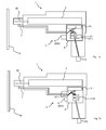
- the safety device 8 of the tool 1 functions as follows.
- Fig. 1a the control volume 15 is charged via the charging connection 27.1.
- the tool 1 is then placed in a ready-to-release state or a secured state.
- the tool 1 has a pneumatic line, which is both part of the charging connection 27.1 and part of the discharge connection 33.1 and which extends from the activation element 33 to the control volume 15.
- the tool 1 further has two separate lines, one of the separate lines being part of the charging connection 27.1 and extending from the activation element 33 to the gas pressure source connection 23 and the other of the separate lines being part of the discharge connection 33.1 and extending from the activation element 33 extends to the pressure sink 40.
- the smallest flow cross section, which determines the delay time of the securing device 8 together with the gas pressure, is present in exactly one of the separate lines, here in the line which extends from the activating element 33 to the pressure sink 40.
- the fast loading and slow unloading of the control volume 15 is thereby realized constructively very advantageous.
- the securing device 8 is set up to transfer the tool 1 into the secured state when the pressure falls below a threshold in the control volume and that the charging connection 27.1 is present when the trigger element 6 is in its idle state 600.
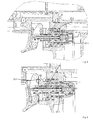
- Fig. 2-8 show sectional views of a still further preferred embodiment of a tool 1 based on Fig. 1a, 1b in different states. It rejects the in Fig. 1 a and 1 b shown and described features.
- FIGS. 2 and 3 show the tool 1 when no compressed air is connected, the standby element 27 is in the securing position.
- Fig. 4 shows the tool 1 with connected compressed air, wherein neither trigger element 6 nor workpiece contact element 7 are actuated - the standby element 27 is in the standby position.
- Fig. 5 shows the tool 1 with trigger element 6 pressed and with the standby element 27 still in the ready position, Fig. 6 the tool 1, after the predetermined time has expired and the tool 1 has been transferred to the secured state, the standby element 27 is now in the securing position.
- Fig. 7 shows the tool 1 in the state of triggering a driving operation, the standby element 27 is in the standby position, Fig. 8 the tool while pressed trigger element 6 and workpiece contact element 7, wherein it is in the secured state - the standby element 27 is in the safety position - and therefore no driving operation is triggered.
- the activation element 33 can be pneumatically reset to that from its first and second position, in which the activation element 33 is in the idle state 600 of the trigger element 6.
- the activation element 33 has a positive surface difference of areas, which are acted upon by gas of the gas pressure source minus surfaces which are connected to the pressure sink 40.
- the securing device 8 has a standby element 27 which can be displaced pneumatically into a securing position and a ready position.
- the tool 1 is in the secured state ( Fig. 2, 3rd . 6 . 8th ) when the standby element 27 is in the safing position and is in the ready to trip state 100 (FIG. Fig. 4, 5 . 7 ) when the standby element 27 is in the standby position.
- the standby element 27 is arranged between the control volume 15 and the gas pressure source connection 23, and the charge connection 27.1 is passed through at least two openings of the standby element 27 ( Fig. 4 ).
- the standby element 27 has a first surface area with a first surface area A1, which can be acted upon by gas pressure of the control volume 15 when the trigger element 6 is in its depressed state 601. It has a second surface area with a second area A2, which can be acted on by gas pressure of the gas pressure source when the trigger element 6 is in its depressed state 601 and when the trigger element 6 is in its idle state 600.
- the first and second surface areas are adapted to direct displacement forces applied to the standby element 27 upon application of pressure. For this they have opposite components of surface normals.
- the first and second surface areas are in a common pneumatic volume when the activation element 33 is in the first position (left or closer to the trigger element) and in two separate volumes when the activation element 33 is in the second Position (on the right or away from the trigger element).
- the first area A1 is greater than the second area A2.
- the standby element 27 is designed as a tube piece, which is open at both end faces and has a central passage 27.3.
- the pipe section has, in addition to the passage 27.3, an axial secondary passage 27.4 which has an opening facing the passage 27.3 and an opening axially spaced therefrom and facing the outside environment of the pipe section.
- the secondary channel 27.4 is part of the charging connection 27.1 (FIG. Fig. 4 ).
- the activation element 33 is movably guided on the standby element 27 as well as relative to the standby element 27.
- the activation element 33 and the standby element 27 are inserted into each other and concentric.
- Outer seal rings 33.2, 33.3, 33.4, 33.5, 33.6, 33.7 of the activation element 33 abut the inner contour of the standby element 27 directly.
- the activation element 33 is also formed as a pipe piece.
- the discharge connection 33.1 extends through two openings of the activation element 33 present in a lateral surface of the activation element 33.1 (FIG. Fig. 5 ). By the activation element 33, the discharge connection 33.1 is defined in the activation position (second position, right).
- the tool 1 has a main triggering valve 12 and a triggering element 21, which is set up to provide a pneumatic triggering connection 21.1 (FIG. Fig. 5 ) from the gas pressure source port 23 to the main trigger valve 12 when the standby element 27 is in the standby position.
- a pneumatic secondary line 27.2 is provided, bypassing the triggering element 21 between the main triggering valve 12 and the gas pressure source connection 23, when the standby element 27 is in the securing position ( Fig. 6 ) or when the activation element 33 in the first position, left ( Fig. 4 ) is located.
- the activation element 33 defines part of the triggering connection 21.1 from the gas pressure source connection 23 to the main triggering valve 12 (FIG. Fig. 5 ).
- the triggering element 21 is movably guided on the activating element 33 and relative to the activating element 33.
- the activation element 33 and the trigger element 21 are inserted into one another.
- the triggering element 21 is here set up to define a pneumatic triggering discharge connection 21.2 between the main triggering valve 12 and the pressure sink 40.
- the trigger element 6 has a coupling element 26 which can be acted upon by the workpiece contact element 7 in any position of the trigger element 21 and which mechanically couples the workpiece contact element 7 and the trigger element 6 to the trigger element 21.
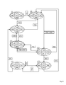
- FIG. 12 is a flowchart illustrating the use of the further preferred embodiment of a tool based on the previous figures in various states, some of which are illustrated in the previous figures (cross references indicated by Roman numerals). States are each circled, events outlined in an angular manner.
- state I the tool 1 is not connected to the gas pressure source. Therefore, the tool is in the locked state 101.
- the trigger element 6 is in the idle state 600, the workpiece contact element 7 in the unactuated state 700.
- the safety device 8 is not active, i. there is no time counter.
- the standby element 27 may be in either the backup position (left position) or the standby position (right position) in this state.
- the tool 1 is then used by connecting 230 to the gas pressure source, whereby the device assumes the triggering state 100.
- the standby element 27 (if it has not already been there in state I) is moved into its standby position. This is due to the area difference causes the surface areas A1 and A2, which are both acted upon in this state by the pressure of the gas pressure source.
- the control volume 15 is “charged” with gas pressure.
- there is a secondary line 27.2 in this state which represents a bridging of the trigger element 21.
- the secondary line 27.2 is thus a non-interruptible from the trigger element 21 connection from the gas pressure source port 23 to the main trigger valve 12th
- a next process state can be achieved (left, second line) in which the workpiece contact element 7 is then in its actuated state 701.
- Trigger element 6 is in the depressed state 601, workpiece contact element 7 in the actuated state 701.
- the trigger element 21 is in its release position, which is achieved by means of the coupling element 26.
- the trip connection 21.1 is made by the main trigger valve 12 to the pressure sink 40, so that the main trigger valve 12 is activated and the driving is performed.
- the driving volume 13 is acted upon by the gas pressure of the gas pressure source, so that the working piston moves in the direction of the tool tip (to the left).
- the working piston 11 moves back to its rest position, so that the control volume 15 then can not be loaded via the ventilation assembly 18 - the elastic Since the trigger element 6 is pressed, 601, and thus the discharge connection 33.1 is made, the pressure in the control volume 15 gradually decreases, ie the countdown is running, the safety device 8 is activated.
- state III can also be reached by pressing 610 of the trigger element 6 in state II, which also the safety device 8 is activated and thus starts a countdown for moving the tool 1 in the secure state 101.
- the control volume 15 has been charged by the charging connection 27.1 in state II and is then slowly discharged via the discharge connection 33.1.
- control volume 15 is separated from the gas pressure source (while, for example, in state II has a connection between these on the charging connection 27.1) and air escapes through the discharge connection 33.1, so that the standby element 27 abruptly after expiry of the predetermined time in the direction the securing position moves.
- the ready element 27 has arrived in the securing position (left position).
- the standby element 27 allows in this position, a secondary line 27.2, which connects the main trigger valve 12 with the gas pressure of the gas pressure source, so that no matter in which position is triggering element 21 or activation element 33, no interruption of this connection is possible.
- an interruption would be necessary to initiate a drive-in process. Therefore, no triggering is possible and thus the tool 1 is in the secured state 101.
- an operation 710 of the workpiece contact element 7, which leads to the state VI and shifts the triggering element into its triggering position can not cause a triggering, since the standby element 27 the secondary line 27.2 defines. In order to emerge from the saved state 101, the user must release the trigger element 6 620.
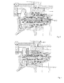
- Fig. 10-Fig. 12 show, based on the previous figures, a variant in which the activation element 33 is also displaceable by means of the workpiece contact element 7.
- the workpiece contact element 7 is mechanically coupled to the activation element 33 such that the workpiece contact element 7 can press the activation element 33 into the activation position (right position); this condition is in FIGS. 11 and 12 shown, wherein the standby element 27 in Fig. 11 is in the ready position and in Fig. 12 in the hedging position.
- This additional mechanical coupling to the activation element 33 is here by way of example and roughly indicated by means of an angled region of the workpiece contact element 7.
- the workpiece contact element 7 is as previously set up to press the triggering element 21 via the coupling element 26. Only when both elements of trigger element 6 and workpiece contact element 7 are unactuated or in the idle state, the activation element 33 can move out of the activation position.
- Fig. 13 shows a flowchart for this variant of Fig. 10-12 , where again states with Roman numbers are referenced - the states II-VI can the Fig. 2-8 are removed, with only the changed mechanical coupling between activation element 33 and workpiece contact element 7 makes a difference, the state otherwise, however, is the same.
- the process builds on the in Fig. 9 shown process;
- the securing device 8 is now already activated by pressing 710 of the workpiece contact element 7, so that it is now in the state VII in the activated state 801, because by the workpiece contact element 7, the activation element 33 is moved to the left position, so that the discharge connection 33.1 is made.
Landscapes
- Engineering & Computer Science (AREA)
- Mechanical Engineering (AREA)
- Physics & Mathematics (AREA)
- Fluid Mechanics (AREA)
- Portable Nailing Machines And Staplers (AREA)
Priority Applications (13)
| Application Number | Priority Date | Filing Date | Title |
|---|---|---|---|
| EP15166582.5A EP3090836A1 (fr) | 2015-05-06 | 2015-05-06 | Outil pour enfoncer des organes de fixation à dispositif de sécurité amélioré |
| US15/569,265 US11065747B2 (en) | 2015-05-06 | 2016-05-02 | Drive-in tool with improved safety device |
| EP16726683.2A EP3291947B1 (fr) | 2015-05-06 | 2016-05-02 | Outil pour enfoncer des organes de fixation à dispositif de sécurité amélioré |
| PCT/US2016/030385 WO2016179081A1 (fr) | 2015-05-06 | 2016-05-02 | Outil d'enfoncement avec dispositif de sécurité amélioré |
| AU2016258594A AU2016258594B2 (en) | 2015-05-06 | 2016-05-02 | Drive-in tool with improved safety device |
| NZ736831A NZ736831A (en) | 2015-05-06 | 2016-05-02 | Drive-in tool with improved safety device |
| EP22199668.9A EP4140652A1 (fr) | 2015-05-06 | 2016-05-02 | Outil pour enfoncer des organes de fixation à dispositif de sécurité amélioré |
| DE102016121221.0A DE102016121221A1 (de) | 2015-05-06 | 2016-11-07 | Eintreibwerkzeug mit verbesserter Sicherheitseinrichtung |
| AU2019203653A AU2019203653B2 (en) | 2015-05-06 | 2019-05-24 | Drive-in tool with improved safety device |
| US17/376,901 US11667017B2 (en) | 2015-05-06 | 2021-07-15 | Drive-in tool with improved safety device |
| AU2021215239A AU2021215239B2 (en) | 2015-05-06 | 2021-08-12 | Drive-in tool with improved safety device |
| AU2023202748A AU2023202748B2 (en) | 2015-05-06 | 2023-05-03 | Drive-in tool with improved safety device |
| US18/318,410 US11964373B2 (en) | 2015-05-06 | 2023-05-16 | Drive-in tool with improved safety device |
Applications Claiming Priority (1)
| Application Number | Priority Date | Filing Date | Title |
|---|---|---|---|
| EP15166582.5A EP3090836A1 (fr) | 2015-05-06 | 2015-05-06 | Outil pour enfoncer des organes de fixation à dispositif de sécurité amélioré |
Publications (1)
| Publication Number | Publication Date |
|---|---|
| EP3090836A1 true EP3090836A1 (fr) | 2016-11-09 |
Family
ID=53175301
Family Applications (3)
| Application Number | Title | Priority Date | Filing Date |
|---|---|---|---|
| EP15166582.5A Withdrawn EP3090836A1 (fr) | 2015-05-06 | 2015-05-06 | Outil pour enfoncer des organes de fixation à dispositif de sécurité amélioré |
| EP22199668.9A Pending EP4140652A1 (fr) | 2015-05-06 | 2016-05-02 | Outil pour enfoncer des organes de fixation à dispositif de sécurité amélioré |
| EP16726683.2A Active EP3291947B1 (fr) | 2015-05-06 | 2016-05-02 | Outil pour enfoncer des organes de fixation à dispositif de sécurité amélioré |
Family Applications After (2)
| Application Number | Title | Priority Date | Filing Date |
|---|---|---|---|
| EP22199668.9A Pending EP4140652A1 (fr) | 2015-05-06 | 2016-05-02 | Outil pour enfoncer des organes de fixation à dispositif de sécurité amélioré |
| EP16726683.2A Active EP3291947B1 (fr) | 2015-05-06 | 2016-05-02 | Outil pour enfoncer des organes de fixation à dispositif de sécurité amélioré |
Country Status (6)
| Country | Link |
|---|---|
| US (3) | US11065747B2 (fr) |
| EP (3) | EP3090836A1 (fr) |
| AU (4) | AU2016258594B2 (fr) |
| DE (1) | DE102016121221A1 (fr) |
| NZ (1) | NZ736831A (fr) |
| WO (1) | WO2016179081A1 (fr) |
Cited By (1)
| Publication number | Priority date | Publication date | Assignee | Title |
|---|---|---|---|---|
| EP3479963A1 (fr) * | 2017-11-01 | 2019-05-08 | Joh. Friedrich Behrens AG | Cloueur à air comprimé pourvu d'un système de soupape de sécurité |
Families Citing this family (8)
| Publication number | Priority date | Publication date | Assignee | Title |
|---|---|---|---|---|
| EP3090836A1 (fr) * | 2015-05-06 | 2016-11-09 | Illinois Tool Works Inc. | Outil pour enfoncer des organes de fixation à dispositif de sécurité amélioré |
| CN108602179B (zh) * | 2015-12-28 | 2021-07-16 | 工机控股株式会社 | 打入机 |
| US11267116B2 (en) | 2016-11-30 | 2022-03-08 | Koki Holdings Co., Ltd. | Drive-in machine |
| US11065749B2 (en) | 2018-03-26 | 2021-07-20 | Tti (Macao Commercial Offshore) Limited | Powered fastener driver |
| US11420312B2 (en) | 2018-12-03 | 2022-08-23 | Black & Decker Inc. | Fastener driving tool trigger assembly |
| JP7222305B2 (ja) * | 2019-04-26 | 2023-02-15 | マックス株式会社 | 空気圧工具 |
| ES2904999T3 (es) * | 2019-07-02 | 2022-04-06 | Bea Gmbh | Clavadora neumática con un dispositivo de seguridad |
| US11491623B2 (en) | 2019-10-02 | 2022-11-08 | Illinois Tool Works Inc. | Fastener driving tool |
Citations (5)
| Publication number | Priority date | Publication date | Assignee | Title |
|---|---|---|---|---|
| US3964659A (en) * | 1975-03-12 | 1976-06-22 | Senco Products, Inc. | Safety firing control means for a fluid operated tool |
| EP1223009A2 (fr) * | 2001-01-16 | 2002-07-17 | Illinois Tool Works Inc. | Détente de sécurité avec dispositif de retard pour un outil de scellement pneumatique |
| EP2767365A1 (fr) | 2013-02-19 | 2014-08-20 | Joh. Friedrich Behrens AG | Cloueur à air comprimé avec déclencheur manuel et capteur de contact |
| DE102013106657A1 (de) | 2013-06-25 | 2015-01-08 | Illinois Tool Works Inc. | Eintreibwerkzeug zum Eintreiben von Befestigungsmitteln in ein Werkstück |
| EP2832502A1 (fr) * | 2013-08-02 | 2015-02-04 | Fasco S.r.l. | Dispositif de sécurité pour une cloueuse |
Family Cites Families (52)
| Publication number | Priority date | Publication date | Assignee | Title |
|---|---|---|---|---|
| US3033236A (en) * | 1959-05-14 | 1962-05-08 | George E Rayman | Torque timing system |
| US3580455A (en) * | 1969-03-21 | 1971-05-25 | Reich Maschf Gmbh Karl | Fastener driving device operating means |
| US3572572A (en) * | 1969-07-22 | 1971-03-30 | Textron Inc | Fluid pressure operated fastener driving device |
| US3730414A (en) * | 1971-08-25 | 1973-05-01 | Senco Products | Fastener applying device |
| US3786978A (en) | 1972-06-05 | 1974-01-22 | Electro Matic Staplers Inc | Electromagnetic stapler |
| US3888404A (en) * | 1973-09-13 | 1975-06-10 | Duo Fast Corp | Safety for fastener driving tool |
| DE3014803C2 (de) | 1980-04-17 | 1985-07-25 | Joh. Friedrich Behrens AG, 2070 Ahrensburg | Druckluftnagler |
| US4550643A (en) * | 1984-05-02 | 1985-11-05 | Duo-Fast Corporation | Fastener driving tool |
| US4679719A (en) | 1985-12-27 | 1987-07-14 | Senco Products, Inc. | Electronic control for a pneumatic fastener driving tool |
| ATE162449T1 (de) * | 1988-04-07 | 1998-02-15 | Pittini Alessandra | Pneumatisches befestigungsmitteleintreibgerät |
| JP2560432Y2 (ja) * | 1993-09-06 | 1998-01-21 | マックス株式会社 | 釘打機用安全装置 |
| JP2568736Y2 (ja) | 1993-12-06 | 1998-04-15 | マックス株式会社 | 可搬形電動ステープル打機 |
| US5551620A (en) | 1994-08-10 | 1996-09-03 | Stanley-Bostitch, Inc. | Convertible contact/sequential trip trigger |
| WO1996012591A1 (fr) | 1994-10-21 | 1996-05-02 | Senco Products, Inc. | Outil pneumatique de pose de fixations et sa commande electronique |
| JP3287172B2 (ja) | 1995-04-05 | 2002-05-27 | マックス株式会社 | 釘打ち機のトリガ装置 |
| JP3351672B2 (ja) | 1995-12-20 | 2002-12-03 | 株式会社東芝 | 加算器 |
| US5862969A (en) | 1997-09-17 | 1999-01-26 | De Poan Pneumatic Corporation | Safety trigger for nailer |
| US5909836A (en) | 1997-10-31 | 1999-06-08 | Illinois Tool Works Inc. | Combustion powered tool with combustion chamber lockout |
| US6145724A (en) | 1997-10-31 | 2000-11-14 | Illinois Tool Works, Inc. | Combustion powered tool with combustion chamber delay |
| US6213372B1 (en) | 2000-08-14 | 2001-04-10 | Mu-Yu Chen | Drive device for a nailing machine |
| US6543664B2 (en) | 2001-03-16 | 2003-04-08 | Illinois Tool Works Inc | Selectable trigger |
| US6357647B1 (en) | 2001-05-23 | 2002-03-19 | Panrex Industrial Co., Ltd. | Nail-driving gun having a single shot operation and a continuous shooting operation which can be selected by controlling acutation order of two members |
| US6523621B1 (en) * | 2001-08-31 | 2003-02-25 | Illinois Tool Works Inc. | Delay-interruption connector for pneumatic tool |
| US6450387B1 (en) | 2002-03-04 | 2002-09-17 | Panrex Industrial Co., Ltd. | Nail-driving gun with safety device |
| TW569882U (en) | 2002-12-25 | 2004-01-01 | Wen-Jou Jang | Switch structure for keystroke type trigger of nailing gun |
| TWI221798B (en) | 2002-12-25 | 2004-10-11 | Wen-Jou Jang | Electronic-controlled staple gun |
| TW567966U (en) | 2002-12-26 | 2003-12-21 | Wen-Jou Jang | Nailing gun structure |
| US7143918B2 (en) | 2003-07-30 | 2006-12-05 | Stanley Fastening Systems, L.P. | Fastener driving device with automatic dual-mode trigger assembly |
| US7163134B2 (en) | 2004-02-09 | 2007-01-16 | Illinois Tool Works Inc. | Repetitive cycle tool logic and mode indicator for combustion powered fastener-driving tool |
| JP4326452B2 (ja) | 2004-10-26 | 2009-09-09 | パナソニック電工株式会社 | 衝撃工具 |
| EP1777040B1 (fr) | 2005-10-19 | 2013-01-16 | Makita Corporation | Outil motorisé |
| NZ572043A (en) | 2006-04-20 | 2010-05-28 | Illinois Tool Works | Fastener-driving tool having trigger control mechanism for alternatively permitting bump firing and sequential firing modes of operation |
| US7225961B1 (en) * | 2006-05-11 | 2007-06-05 | Samson Power Tool Co., Ltd. | Air path arrangement for pneumatic nail gun |
| JP4692932B2 (ja) | 2006-09-14 | 2011-06-01 | 日立工機株式会社 | 電動式打込機 |
| CA2586464A1 (fr) | 2007-04-27 | 2008-10-27 | Crane Canada Co. | Accepteur de billets de banque avec case de reception amovible |
| EP2209593B1 (fr) | 2007-10-05 | 2016-07-20 | Senco Brands, Inc | Outil d'entraînement de fixation utilisant une source de gaz |
| TW200948553A (en) | 2008-05-16 | 2009-12-01 | Apach Ind Co Ltd | Switching device for single discharge and continuous discharge of nail gun |
| US7975890B2 (en) | 2008-08-26 | 2011-07-12 | Jhih-Siang Tang | Switching mechanism for stapling modes of a stapler |
| US8336749B2 (en) | 2009-03-31 | 2012-12-25 | Illinois Tool Works Inc. | Single switched dual firing condition combustion nailer |
| US20120097730A1 (en) | 2010-10-20 | 2012-04-26 | De Poan Pneumatic Corp. | Nail-pushing rod restoring apparatus for pneumatic nail gun |
| TWI401143B (zh) | 2010-11-03 | 2013-07-11 | Basso Ind Corp | Electric nail gun double switch device |
| TWM403405U (en) | 2010-11-03 | 2011-05-11 | Basso Ind Corp | Control structure of electrical nailing gun |
| EP2633956B1 (fr) | 2012-03-02 | 2016-03-02 | Stanley Fastening Systems L.P. | Outil de fixation avec deux poignées pneumatiques |
| US9550288B2 (en) | 2012-10-22 | 2017-01-24 | Illinois Tool Works Inc. | Fastener-driving tool including a reversion trigger |
| US9381633B2 (en) | 2012-10-22 | 2016-07-05 | Illinois Tool Works Inc. | Fastener-driving tool including a reversion trigger |
| US9486907B2 (en) | 2013-01-15 | 2016-11-08 | Illinois Tool Works Inc. | Reversion trigger for combustion-powered fastener-driving tool |
| DE102013106658A1 (de) * | 2013-06-25 | 2015-01-08 | Illinois Tool Works Inc. | Eintreibwerkzeug zum Eintreiben von Befestigungsmitteln in ein Werkstück |
| US9662776B2 (en) | 2013-12-17 | 2017-05-30 | Illinois Tool Works Inc. | Fastener-driving tool including a reversion trigger with a damper |
| EP3090836A1 (fr) * | 2015-05-06 | 2016-11-09 | Illinois Tool Works Inc. | Outil pour enfoncer des organes de fixation à dispositif de sécurité amélioré |
| CN108602179B (zh) * | 2015-12-28 | 2021-07-16 | 工机控股株式会社 | 打入机 |
| EP3450108B1 (fr) * | 2016-04-28 | 2022-01-26 | Koki Holdings Co., Ltd. | Dispositif d'entraînement |
| US11065749B2 (en) * | 2018-03-26 | 2021-07-20 | Tti (Macao Commercial Offshore) Limited | Powered fastener driver |
-
2015
- 2015-05-06 EP EP15166582.5A patent/EP3090836A1/fr not_active Withdrawn
-
2016
- 2016-05-02 AU AU2016258594A patent/AU2016258594B2/en active Active
- 2016-05-02 WO PCT/US2016/030385 patent/WO2016179081A1/fr not_active Ceased
- 2016-05-02 NZ NZ736831A patent/NZ736831A/en unknown
- 2016-05-02 EP EP22199668.9A patent/EP4140652A1/fr active Pending
- 2016-05-02 EP EP16726683.2A patent/EP3291947B1/fr active Active
- 2016-05-02 US US15/569,265 patent/US11065747B2/en active Active
- 2016-11-07 DE DE102016121221.0A patent/DE102016121221A1/de active Pending
-
2019
- 2019-05-24 AU AU2019203653A patent/AU2019203653B2/en active Active
-
2021
- 2021-07-15 US US17/376,901 patent/US11667017B2/en active Active
- 2021-08-12 AU AU2021215239A patent/AU2021215239B2/en active Active
-
2023
- 2023-05-03 AU AU2023202748A patent/AU2023202748B2/en active Active
- 2023-05-16 US US18/318,410 patent/US11964373B2/en active Active
Patent Citations (5)
| Publication number | Priority date | Publication date | Assignee | Title |
|---|---|---|---|---|
| US3964659A (en) * | 1975-03-12 | 1976-06-22 | Senco Products, Inc. | Safety firing control means for a fluid operated tool |
| EP1223009A2 (fr) * | 2001-01-16 | 2002-07-17 | Illinois Tool Works Inc. | Détente de sécurité avec dispositif de retard pour un outil de scellement pneumatique |
| EP2767365A1 (fr) | 2013-02-19 | 2014-08-20 | Joh. Friedrich Behrens AG | Cloueur à air comprimé avec déclencheur manuel et capteur de contact |
| DE102013106657A1 (de) | 2013-06-25 | 2015-01-08 | Illinois Tool Works Inc. | Eintreibwerkzeug zum Eintreiben von Befestigungsmitteln in ein Werkstück |
| EP2832502A1 (fr) * | 2013-08-02 | 2015-02-04 | Fasco S.r.l. | Dispositif de sécurité pour une cloueuse |
Cited By (3)
| Publication number | Priority date | Publication date | Assignee | Title |
|---|---|---|---|---|
| EP3479963A1 (fr) * | 2017-11-01 | 2019-05-08 | Joh. Friedrich Behrens AG | Cloueur à air comprimé pourvu d'un système de soupape de sécurité |
| WO2019086180A1 (fr) * | 2017-11-01 | 2019-05-09 | Joh. Friedrich Behrens Ag | Cloueuse pneumatique à ensemble soupape de sécurité |
| US11541522B2 (en) | 2017-11-01 | 2023-01-03 | Joh. Friedrich Behrens Ag | Compressed air nailer with safety valve arrangement |
Also Published As
| Publication number | Publication date |
|---|---|
| US11065747B2 (en) | 2021-07-20 |
| EP4140652A1 (fr) | 2023-03-01 |
| NZ736831A (en) | 2019-05-31 |
| US11964373B2 (en) | 2024-04-23 |
| AU2016258594B2 (en) | 2019-03-14 |
| US11667017B2 (en) | 2023-06-06 |
| AU2019203653B2 (en) | 2021-05-13 |
| AU2019203653A1 (en) | 2019-06-13 |
| WO2016179081A1 (fr) | 2016-11-10 |
| AU2023202748A1 (en) | 2023-05-18 |
| AU2016258594A1 (en) | 2017-11-16 |
| EP3291947B1 (fr) | 2022-10-05 |
| AU2021215239B2 (en) | 2023-03-30 |
| EP3291947A1 (fr) | 2018-03-14 |
| DE102016121221A1 (de) | 2017-11-02 |
| US20180117747A1 (en) | 2018-05-03 |
| AU2023202748B2 (en) | 2025-07-03 |
| US20210339369A1 (en) | 2021-11-04 |
| AU2021215239A1 (en) | 2021-09-02 |
| US20230302615A1 (en) | 2023-09-28 |
Similar Documents
| Publication | Publication Date | Title |
|---|---|---|
| EP3090836A1 (fr) | Outil pour enfoncer des organes de fixation à dispositif de sécurité amélioré | |
| EP2767365B1 (fr) | Cloueur à air comprimé avec déclencheur manuel et capteur de contact | |
| DE69806161T2 (de) | Pneumatisch-hydraulisches nietgerät | |
| EP2565469B1 (fr) | Blind rivet setting device with pressure generator | |
| DE60214540T2 (de) | Nietsetzwerkzeug mit schnellverbindungs-nasengehäuse | |
| EP3257633B1 (fr) | Cloueur a air comprime comprenant une chambre de commande de securite | |
| CH671600A5 (fr) | ||
| EP3446833B1 (fr) | Cloueur à air comprimé pourvu de dispositif de soupape de sécurité | |
| DE10011340A1 (de) | Pneumatisch-hydraulisches Blindnietgerät | |
| DE2055801B2 (de) | Bremseinrichtung fuer den anhaenger eines fahrzeugs, das einen von einer druckmittelquelle gespeisten hydraulikkreis mit einem verbraucher hat | |
| EP3083150B1 (fr) | Appareil de travail | |
| EP3697573B1 (fr) | Clouseuse à air comprimé pourvue d'un actionneur de sécurité | |
| DE60213172T2 (de) | Verbinder für den Pneumatikanschluss eines pneumatischen Werkzeugs und dessen Kombination | |
| EP1399297B1 (fr) | Dispositif d'expulsion actionne par un agent de pression | |
| DE10254964A1 (de) | Setzgerät | |
| EP3666469A1 (fr) | Cloueur pneumatique doté d'un dispositif de sécurité | |
| EP3703911A1 (fr) | Cloueuse pneumatique à ensemble soupape de sécurité | |
| EP3471921B1 (fr) | Cloueur a air comprime comprenant un declenchement sequentiel et par contact | |
| DE1949951C3 (de) | Nietvorrichtung zum Setzen von Nieten, bei denen ein Schließring in andern Setzkopf des Nietes abgelegenen Ende ausgebildete Schließnuten eingedrückt und zu dem Schließkopf verformt wird | |
| DE10228036B4 (de) | Über expandierende Gase angetriebbares Setzgerät mit Magazin für Befestigungselemente | |
| DE10341821B4 (de) | Setzgerät | |
| DE202012101490U1 (de) | Nietsetzgerät mit Ventilmodul | |
| DE202013104109U1 (de) | Hydraulikwerkzeug sowie hydraulisch betätigte Werkzeugaufnahme | |
| EP3760379B1 (fr) | Cloueur pneumatique doté d'un dispositif de sécurité | |
| DE19804456C1 (de) | Auslösegesichertes Eintreibgerät für Befestigungsmittel |
Legal Events
| Date | Code | Title | Description |
|---|---|---|---|
| PUAI | Public reference made under article 153(3) epc to a published international application that has entered the european phase |
Free format text: ORIGINAL CODE: 0009012 |
|
| AK | Designated contracting states |
Kind code of ref document: A1 Designated state(s): AL AT BE BG CH CY CZ DE DK EE ES FI FR GB GR HR HU IE IS IT LI LT LU LV MC MK MT NL NO PL PT RO RS SE SI SK SM TR |
|
| AX | Request for extension of the european patent |
Extension state: BA ME |
|
| STAA | Information on the status of an ep patent application or granted ep patent |
Free format text: STATUS: THE APPLICATION IS DEEMED TO BE WITHDRAWN |
|
| 18D | Application deemed to be withdrawn |
Effective date: 20170510 |