EP3090841B1 - Système de contrôle et robot industriel le comprenant - Google Patents
Système de contrôle et robot industriel le comprenant Download PDFInfo
- Publication number
- EP3090841B1 EP3090841B1 EP14874313.1A EP14874313A EP3090841B1 EP 3090841 B1 EP3090841 B1 EP 3090841B1 EP 14874313 A EP14874313 A EP 14874313A EP 3090841 B1 EP3090841 B1 EP 3090841B1
- Authority
- EP
- European Patent Office
- Prior art keywords
- power supply
- control
- motor
- servo
- regenerating
- Prior art date
- Legal status (The legal status is an assumption and is not a legal conclusion. Google has not performed a legal analysis and makes no representation as to the accuracy of the status listed.)
- Active
Links
Images

Classifications
-
- B—PERFORMING OPERATIONS; TRANSPORTING
- B25—HAND TOOLS; PORTABLE POWER-DRIVEN TOOLS; MANIPULATORS
- B25J—MANIPULATORS; CHAMBERS PROVIDED WITH MANIPULATION DEVICES
- B25J9/00—Program-controlled manipulators
- B25J9/16—Program controls
- B25J9/1602—Program controls characterised by the control system, structure, architecture
- B25J9/161—Hardware, e.g. neural networks, fuzzy logic, interfaces, processor
-
- H—ELECTRICITY
- H02—GENERATION; CONVERSION OR DISTRIBUTION OF ELECTRIC POWER
- H02M—APPARATUS FOR CONVERSION BETWEEN AC AND AC, BETWEEN AC AND DC, OR BETWEEN DC AND DC, AND FOR USE WITH MAINS OR SIMILAR POWER SUPPLY SYSTEMS; CONVERSION OF DC OR AC INPUT POWER INTO SURGE OUTPUT POWER; CONTROL OR REGULATION THEREOF
- H02M5/00—Conversion of AC power input into AC power output, e.g. for change of voltage, for change of frequency, for change of number of phases
- H02M5/40—Conversion of AC power input into AC power output, e.g. for change of voltage, for change of frequency, for change of number of phases with intermediate conversion into DC
- H02M5/42—Conversion of AC power input into AC power output, e.g. for change of voltage, for change of frequency, for change of number of phases with intermediate conversion into DC by static converters
- H02M5/44—Conversion of AC power input into AC power output, e.g. for change of voltage, for change of frequency, for change of number of phases with intermediate conversion into DC by static converters using discharge tubes or semiconductor devices to convert the intermediate DC into AC
- H02M5/453—Conversion of AC power input into AC power output, e.g. for change of voltage, for change of frequency, for change of number of phases with intermediate conversion into DC by static converters using discharge tubes or semiconductor devices to convert the intermediate DC into AC using devices of a triode or transistor type requiring continuous application of a control signal
- H02M5/458—Conversion of AC power input into AC power output, e.g. for change of voltage, for change of frequency, for change of number of phases with intermediate conversion into DC by static converters using discharge tubes or semiconductor devices to convert the intermediate DC into AC using devices of a triode or transistor type requiring continuous application of a control signal using semiconductor devices only
- H02M5/4585—Conversion of AC power input into AC power output, e.g. for change of voltage, for change of frequency, for change of number of phases with intermediate conversion into DC by static converters using discharge tubes or semiconductor devices to convert the intermediate DC into AC using devices of a triode or transistor type requiring continuous application of a control signal using semiconductor devices only having a rectifier with controlled elements
-
- H—ELECTRICITY
- H02—GENERATION; CONVERSION OR DISTRIBUTION OF ELECTRIC POWER
- H02P—CONTROL OR REGULATION OF ELECTRIC MOTORS, ELECTRIC GENERATORS OR DYNAMO-ELECTRIC CONVERTERS; CONTROLLING TRANSFORMERS, REACTORS OR CHOKE COILS
- H02P3/00—Arrangements for stopping or slowing electric motors, generators, or dynamo-electric converters
- H02P3/06—Arrangements for stopping or slowing electric motors, generators, or dynamo-electric converters for stopping or slowing an individual dynamo-electric motor or dynamo-electric converter
- H02P3/18—Arrangements for stopping or slowing electric motors, generators, or dynamo-electric converters for stopping or slowing an individual dynamo-electric motor or dynamo-electric converter for stopping or slowing an AC motor
- H02P3/22—Arrangements for stopping or slowing electric motors, generators, or dynamo-electric converters for stopping or slowing an individual dynamo-electric motor or dynamo-electric converter for stopping or slowing an AC motor by short-circuit or resistive braking
-
- H—ELECTRICITY
- H02—GENERATION; CONVERSION OR DISTRIBUTION OF ELECTRIC POWER
- H02P—CONTROL OR REGULATION OF ELECTRIC MOTORS, ELECTRIC GENERATORS OR DYNAMO-ELECTRIC CONVERTERS; CONTROLLING TRANSFORMERS, REACTORS OR CHOKE COILS
- H02P5/00—Arrangements specially adapted for regulating or controlling the speed or torque of two or more electric motors
- H02P5/74—Arrangements specially adapted for regulating or controlling the speed or torque of two or more electric motors controlling two or more AC dynamo-electric motors
-
- H—ELECTRICITY
- H02—GENERATION; CONVERSION OR DISTRIBUTION OF ELECTRIC POWER
- H02P—CONTROL OR REGULATION OF ELECTRIC MOTORS, ELECTRIC GENERATORS OR DYNAMO-ELECTRIC CONVERTERS; CONTROLLING TRANSFORMERS, REACTORS OR CHOKE COILS
- H02P6/00—Arrangements for controlling synchronous motors or other dynamo-electric motors using electronic commutation dependent on the rotor position; Electronic commutators therefor
- H02P6/24—Arrangements for stopping
-
- G—PHYSICS
- G05—CONTROLLING; REGULATING
- G05B—CONTROL OR REGULATING SYSTEMS IN GENERAL; FUNCTIONAL ELEMENTS OF SUCH SYSTEMS; MONITORING OR TESTING ARRANGEMENTS FOR SUCH SYSTEMS OR ELEMENTS
- G05B2219/00—Program-control systems
- G05B2219/30—Nc systems
- G05B2219/40—Robotics, robotics mapping to robotics vision
- G05B2219/40462—Constant consumed energy, regenerate acceleration energy during deceleration
-
- G—PHYSICS
- G05—CONTROLLING; REGULATING
- G05B—CONTROL OR REGULATING SYSTEMS IN GENERAL; FUNCTIONAL ELEMENTS OF SUCH SYSTEMS; MONITORING OR TESTING ARRANGEMENTS FOR SUCH SYSTEMS OR ELEMENTS
- G05B2219/00—Program-control systems
- G05B2219/30—Nc systems
- G05B2219/41—Servomotor, servo controller till figures
- G05B2219/41294—DC-to-AC converter
-
- Y—GENERAL TAGGING OF NEW TECHNOLOGICAL DEVELOPMENTS; GENERAL TAGGING OF CROSS-SECTIONAL TECHNOLOGIES SPANNING OVER SEVERAL SECTIONS OF THE IPC; TECHNICAL SUBJECTS COVERED BY FORMER USPC CROSS-REFERENCE ART COLLECTIONS [XRACs] AND DIGESTS
- Y10—TECHNICAL SUBJECTS COVERED BY FORMER USPC
- Y10S—TECHNICAL SUBJECTS COVERED BY FORMER USPC CROSS-REFERENCE ART COLLECTIONS [XRACs] AND DIGESTS
- Y10S901/00—Robots
- Y10S901/02—Arm motion controller
Definitions
- the present invention relates to an industrial robot having a robot control system for controlling a robot comprising a servo motor.
- the regenerative energy generated when a servo motor connected to a rotational axis of a movable portion of a robot arm or the like is slowed down is usually smaller than the regenerative energy generated when a servo motor driving a rotational axis of a movable portion of a machine tool or the like is slowed down. Therefore, when the regenerative energy is expected to increase according to an increase of operation load factor of a robot, reinforcing the resistance regenerating function has been general rather than adding the power supply regenerating function.
- JPS60191979 relates to an electric motor control device for an elevator which performs variable voltage variable frequency control of a plurality of car driving motors for an elevator.
- US2013/113411 relates to a servomotor drive device having a first converter, a regenerative resistor circuit having a first switching element and a regenerative resistor, a first connection part configured to connect a second converter in parallel to the regenerative resistor circuit in an attachable and detachable manner, and a first control unit configured to control the on and off states of the first switching element.
- JP2013220478A relates to an electric power regeneration method which involves forming of operation plan of combined redundant robot to take energy demand and supply balance, and operating of redundant robot with other combined mechanical apparatus based on operation plan.
- the present invention is made considering the above-mentioned problems of the conventional art and its object is to provide a robot control system capable of suppressing the increase of the development cost and adding the power supply regenerating function.
- the industrial robot according to the present invention is defined by the subject matter of independent claim 1, with preferred embodiments defined in the dependent claims.
- a robot control system capable of suppressing increase of the development cost and adding the power supply regenerating function can be provided.
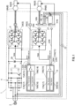
- FIG. 1 a robot control system according to an embodiment of the present invention will be described referring to FIG. 1 .
- an AC current from a three-phase AC power supply 2 is supplied to a converter 4 having a plurality of (six in the example) diodes (rectifier elements) 3, and the AC current is converted into a DC current in the converter 4.
- the DC current generated in the converter 4 is supplied to a plurality of (N in the example) inverters (DC-AC switching devices) 5 (5A, 5N).
- the number N of installed inverters 5 is determined according to the number of drive shafts and external axes of a robot. For example, when a six-axis articulated robot has three external axes, the number N of installed inverters 5 is nine (six and three makes nine).
- Each inverter 5 has a plurality of (six in the example) diodes 6 and a plurality of (six in the example) switching elements 7 each connected in parallel with the corresponding one of the plurality of diodes 6.
- Each inverter 5 inverts the DC current supplied from the converter 4 into an AC current and supplies the same into each servo motor 8 (8A, 8N).
- Motor sensors (encoders) 9 (9A, 9N) are attached to their respective servo motors 8.
- a resistance regenerating circuit 10 is provided between the converter 4 and the inverters 5.
- the resistance regenerating circuit 10 is configured by connecting a regenerative resistor 11 and a switching element 12 in series.
- the robot control system 1 further comprises a servo control device (servo board) 13 for controlling drive of the servo motors 8.
- the servo control device 13 has a plurality of (N in the example) motor control portions 14 (14A, 14N) for controlling the respective servo motors 8 and a plurality of (N in the example) control port portions 15 (15A, 15N) corresponding to the plurality of motor control portions 14.
- Each motor control portion 14 controls drive of the corresponding servo motor 8 based on a signal from the corresponding motor sensor 9 attached to the same servo motor 8.
- each of the plurality of motor control portions 14 includes a power supply regenerating control function portion 16 (16A, 16N) for controlling a power supply regenerating circuit and also is configured so that the power supply regenerating control function portion 16 and a control function portion 17 (17A, 17N) for the servo motor 8 can be switched.
- the power supply regenerating control function portion 16 and the control function portion 17 for the servo motor 8 may be switched by changing settings or automatic detection.
- a connector 18N of the servo motor 9N of the N axis is connected to a connector 19N of the inverter 5N for the N axis and also the inverter 5N for the N axis is connected to a port 20N for PWM of the control port portion 15N for the N axis.
- a connector 21N of the motor sensor 9N attached to the servo motor 8N of the N axis is connected to a port 22N for sensor communication of the control port portion 14N for the N axis via a wiring 23N for sensor communication.
- a reactor 24 is connected to the three-phase AC power supply 2 and also a primary voltage sensor portion (phase detection portion) 26 for detecting primary voltage is provided to a wiring 25 connecting the reactor 24 and the three-phase AC power supply 2.
- a connector 27 of the primary voltage sensor portion 26 is connected to the port 22N for sensor communication of the control port portion 14N for the N axis.
- the connector 28 of the reactor 24 is connected to the connector 19N of the inverter 5N for the N axis.
- the inverter 5N for the servo motor 8N of the N axis comprises a configuration in common with an inverter configuring a power supply regenerating circuit, and the both can be used in common.
- the power supply regenerating function by the power supply regenerative circuit including the inverter 5N for the N axis, reactor 24, and the primary voltage sensor portion 26 works.
- the level of the smoothing capacitor 29 of PN becomes the predetermined value or more, the regenerative energy is consumed in the resistance regenerating circuit 10.
- the power supply regenerating control function portion 16 is standardly implemented in the servo control device 13 controlling drive of the servo motor 8, and one of the plurality of control ports 15 which have been previously prepared in the servo control device 13 is diverted so as to switch and properly select whether the port is used as a motor control port or a power supply regenerating port by changing settings or automatic detection. Therefore, a new control portion for power supply regenerating control does not need to be provided even when the power supply regenerating function is added corresponding to requests of a user. Thereby, increase of the development cost according to addition of the power supply regenerating function can be suppressed.
- the power supply regenerating function can be provided by diverting the inverter 5 for robot control, it is not necessary to develop a new inverter for power supply regeneration separately, and therefore increase of the development cost according to addition of the power supply regenerating function can be further suppressed.
- the motor control portion 14N for the N axis is used for power supply regeneration
- the motor control portion 14 used for power supply regeneration is not limited to that for the N axis.
- using the motor control portion 14A for a first axis for power supply regeneration is also possible, and the port 20A for PWM of the control port 15A for the first axis and the port 22A for sensor communication are used for power supply regeneration in the case.
- FIG. 2 illustrates a configuration when the regenerating function is reinforced in a conventional robot control system.
- a motor control portion 102 of a servo control device thereof does not comprise the power supply regenerating control function. Therefore, a regenerative resistor 103 is added to the resistance regenerating circuit 10 in order to deal with increase of the regenerative energy. Namely, the additional regenerative resistor 103 is provided in parallel with the standardly mounted regenerative resistor 11.
- the power supply regenerating function can be added easily as above, and therefore the regenerative resistor does not need to be added and energy can be utilized effectively.
Landscapes
- Engineering & Computer Science (AREA)
- Power Engineering (AREA)
- Automation & Control Theory (AREA)
- Mathematical Physics (AREA)
- Evolutionary Computation (AREA)
- Fuzzy Systems (AREA)
- Physics & Mathematics (AREA)
- Software Systems (AREA)
- Robotics (AREA)
- Mechanical Engineering (AREA)
- Artificial Intelligence (AREA)
- Control Of Multiple Motors (AREA)
- Manipulator (AREA)
- Control Of Ac Motors In General (AREA)
- Inverter Devices (AREA)
Claims (3)
- Robot industriel comprenant un système de commande (1), le système de commande comprenant :un convertisseur (4) configuré pour convertir un courant alternatif, CA, d'une alimentation en puissance CA (2) en un courant continu, CC ;un onduleur (5) configuré pour inverser une puissance CC fournie depuis le convertisseur (4) en une puissance CA ;un dispositif de servocommande configuré pour commander un entraînement d'une pluralité de servomoteurs (8) sur la base d'un signal émanant d'un capteur de moteur (9) fixé aux servomoteurs (8), etun circuit de régénération de résistance (10) configuré pour consommer une énergie régénérative générée dans les servomoteurs (8),dans lequel le dispositif de servocommande (13) présente une pluralité de parties de commande de moteur (14) configurées pour permettre à la pluralité de servomoteurs (8) d'être commandés et une pluralité de parties de port de commande (15) correspondant à la pluralité de parties de commande de moteur (14),dans lequel au moins l'une de la pluralité de parties de commande de moteur (14) présente une partie de fonction de commande de régénération d'alimentation en puissance (16) configurée pour commander un circuit de régénération d'alimentation en puissance comprenant un onduleur présentant une configuration en commun avec l'onduleur (5) pour le servomoteur de manière à être utilisé en commun pour les deux fonctions de régénération et de conduite et est configurée de sorte que la partie de fonction de commande de régénération d'alimentation en puissance (16) et une partie de fonction de commande (17) pour le servomoteur (8) puissent être commutées selon qu'un objet à relier à la partie de port de commande (15) est le circuit de régénération d'alimentation en puissance ou le servomoteur (8),caractérisé en ce que le circuit de régénération d'alimentation en puissance comprend en outre un réacteur (24) relié à l'alimentation en puissance CA (2) et une partie de capteur de tension primaire (26) reliée à un câblage (25) reliant le réacteur et l'alimentation en puissance de courant CA de manière à détecter une tension primaire, le réacteur (24) étant relié à l'onduleur (5) à utiliser en commun pour les deux fonctions de régénération et de conduite, et la partie de capteur de tension primaire (26) étant reliée à l'au moins une de la pluralité de parties de commande de moteur (14).
- Robot industriel selon la revendication 1, dans lequel l'intégralité de la pluralité de parties de commande de moteur (14) présentent la partie de fonction de commande de régénération d'alimentation en puissance (16).
- Robot industriel selon la revendication 1 ou 2, dans lequel l'onduleur (5) présente une pluralité d'éléments de redresseur (6) et une pluralité d'éléments de commutation (7) qui sont chacun reliés en parallèle à l'un correspondant de la pluralité d'éléments de redresseur (6).
Applications Claiming Priority (2)
| Application Number | Priority Date | Filing Date | Title |
|---|---|---|---|
| JP2013270299A JP5813746B2 (ja) | 2013-12-26 | 2013-12-26 | ロボット制御システム |
| PCT/JP2014/083716 WO2015098753A1 (fr) | 2013-12-26 | 2014-12-19 | Système de commande de robot |
Publications (3)
| Publication Number | Publication Date |
|---|---|
| EP3090841A1 EP3090841A1 (fr) | 2016-11-09 |
| EP3090841A4 EP3090841A4 (fr) | 2017-12-13 |
| EP3090841B1 true EP3090841B1 (fr) | 2025-03-19 |
Family
ID=53478610
Family Applications (1)
| Application Number | Title | Priority Date | Filing Date |
|---|---|---|---|
| EP14874313.1A Active EP3090841B1 (fr) | 2013-12-26 | 2014-12-19 | Système de contrôle et robot industriel le comprenant |
Country Status (7)
| Country | Link |
|---|---|
| US (1) | US9979327B2 (fr) |
| EP (1) | EP3090841B1 (fr) |
| JP (1) | JP5813746B2 (fr) |
| KR (2) | KR20160119078A (fr) |
| CN (1) | CN106103008B (fr) |
| TW (1) | TWI577514B (fr) |
| WO (1) | WO2015098753A1 (fr) |
Families Citing this family (7)
| Publication number | Priority date | Publication date | Assignee | Title |
|---|---|---|---|---|
| US9800188B2 (en) * | 2015-09-15 | 2017-10-24 | Regal Beloit America, Inc. | Hybrid drive circuit for variable speed induction motor |
| US10193488B2 (en) * | 2016-01-14 | 2019-01-29 | Regal Beloit America, Inc. | Methods and systems for reducing conducted electromagnetic interference |
| JP6998115B2 (ja) * | 2017-02-27 | 2022-01-18 | 川崎重工業株式会社 | ロボットコントローラ |
| DE102017009878A1 (de) * | 2017-10-23 | 2019-04-25 | Kuka Deutschland Gmbh | Steuerungssystem und Verfahren zum Betreiben eines elektrischen Motors |
| JP2019093459A (ja) * | 2017-11-20 | 2019-06-20 | セイコーエプソン株式会社 | ロボット |
| JP7152238B2 (ja) * | 2018-10-03 | 2022-10-12 | 川崎重工業株式会社 | ロボット制御装置 |
| JP6865262B2 (ja) * | 2018-12-26 | 2021-04-28 | 川崎重工業株式会社 | ロボットシステムの制御装置 |
Citations (1)
| Publication number | Priority date | Publication date | Assignee | Title |
|---|---|---|---|---|
| JP2013220478A (ja) * | 2012-04-12 | 2013-10-28 | Jtekt Corp | 機械装置間の電力回生方法及び機械装置間の電力回生システム |
Family Cites Families (14)
| Publication number | Priority date | Publication date | Assignee | Title |
|---|---|---|---|---|
| JPS60191979A (ja) | 1984-03-11 | 1985-09-30 | 三菱電機株式会社 | エレベ−タ用電動機制御装置 |
| CN1067001A (zh) * | 1991-05-20 | 1992-12-16 | 中国航空航天工具协会 | 平面磨床用组合导磁夹具元件系统及其加工检测方法 |
| JPH08216075A (ja) * | 1995-02-16 | 1996-08-27 | Toshiba Corp | マニピュレータ制御装置 |
| KR100439466B1 (ko) * | 1995-09-11 | 2004-09-18 | 가부시키가이샤 야스가와덴끼 | 로봇제어장치 |
| JPH11289793A (ja) * | 1998-03-31 | 1999-10-19 | Sumitomo Heavy Ind Ltd | 高調波抑制型電源回生コンバータを備えた電動射出成形機 |
| JP2000201492A (ja) * | 1998-12-28 | 2000-07-18 | Ishikawajima Transport Machinery Co Ltd | 電動機の駆動方法及び装置 |
| CN1601885A (zh) * | 2003-09-25 | 2005-03-30 | 乐金电子(天津)电器有限公司 | Bldc电机的控制旋转速度用的f/g脉冲转换装置 |
| CN101004932A (zh) * | 2007-01-12 | 2007-07-25 | 明基电通信息技术有限公司 | 主轴马达速度反馈信号侦测装置与方法及其光驱 |
| KR20110039972A (ko) * | 2009-10-13 | 2011-04-20 | (주)인텍에프에이 | 기판 이송용 로봇 제어 시스템 |
| JP5043915B2 (ja) | 2009-11-04 | 2012-10-10 | 山洋電気株式会社 | モータ駆動用電源装置 |
| JP5540753B2 (ja) | 2010-02-15 | 2014-07-02 | 株式会社デンソーウェーブ | ロボットシステム |
| JP5260718B2 (ja) | 2011-11-08 | 2013-08-14 | ファナック株式会社 | 産業用ロボットの可動部の回転軸に接続されたサーボモータを駆動するサーボモータ駆動装置 |
| CN102424075B (zh) * | 2011-11-22 | 2013-01-23 | 北京邮电大学 | 基于平衡杆控制的刚柔耦合走钢丝机器人 |
| JP5857845B2 (ja) | 2012-03-29 | 2016-02-10 | 株式会社デンソーウェーブ | ロボットシステム |
-
2013
- 2013-12-26 JP JP2013270299A patent/JP5813746B2/ja active Active
-
2014
- 2014-12-19 US US15/108,497 patent/US9979327B2/en active Active
- 2014-12-19 KR KR1020167020267A patent/KR20160119078A/ko not_active Ceased
- 2014-12-19 CN CN201480071012.1A patent/CN106103008B/zh active Active
- 2014-12-19 KR KR1020187030827A patent/KR102239951B1/ko active Active
- 2014-12-19 EP EP14874313.1A patent/EP3090841B1/fr active Active
- 2014-12-19 WO PCT/JP2014/083716 patent/WO2015098753A1/fr not_active Ceased
- 2014-12-24 TW TW103145328A patent/TWI577514B/zh active
Patent Citations (1)
| Publication number | Priority date | Publication date | Assignee | Title |
|---|---|---|---|---|
| JP2013220478A (ja) * | 2012-04-12 | 2013-10-28 | Jtekt Corp | 機械装置間の電力回生方法及び機械装置間の電力回生システム |
Also Published As
| Publication number | Publication date |
|---|---|
| CN106103008A (zh) | 2016-11-09 |
| KR20180120779A (ko) | 2018-11-06 |
| CN106103008B (zh) | 2018-07-27 |
| EP3090841A1 (fr) | 2016-11-09 |
| KR102239951B1 (ko) | 2021-04-13 |
| TWI577514B (zh) | 2017-04-11 |
| JP2015123554A (ja) | 2015-07-06 |
| EP3090841A4 (fr) | 2017-12-13 |
| JP5813746B2 (ja) | 2015-11-17 |
| US9979327B2 (en) | 2018-05-22 |
| TW201538292A (zh) | 2015-10-16 |
| WO2015098753A1 (fr) | 2015-07-02 |
| US20160329841A1 (en) | 2016-11-10 |
| KR20160119078A (ko) | 2016-10-12 |
Similar Documents
| Publication | Publication Date | Title |
|---|---|---|
| EP3090841B1 (fr) | Système de contrôle et robot industriel le comprenant | |
| JP5260719B2 (ja) | 停電の有無を判定する停電判定部を有するモータ駆動装置 | |
| US9048733B2 (en) | Motor driving device having reactive current instruction generating unit | |
| JP5552564B1 (ja) | 多軸ロボットの動力遮断装置及び多軸ロボット | |
| JP5260718B2 (ja) | 産業用ロボットの可動部の回転軸に接続されたサーボモータを駆動するサーボモータ駆動装置 | |
| WO2019239628A1 (fr) | Convertisseur et dispositif de commande de moteur | |
| JP2018536376A (ja) | 産業用ロボットのための電気駆動装置 | |
| CN102739129B (zh) | 可连接直流交流变换装置的电动机驱动控制装置 | |
| US9588508B2 (en) | Master device that changes data communication speed in accordance with the number of slave devices | |
| JP7803080B2 (ja) | 電力供給システム、及び電力供給ユニット | |
| JP2018207753A (ja) | 蓄電装置の異常検出部を有するモータ駆動システム | |
| JP6099004B1 (ja) | インバータ装置及びインバータ装置の製造方法 | |
| JP6608096B1 (ja) | コンバータ及びモータ制御装置 | |
| CN104170203B (zh) | 多功能i/o装置 | |
| JP6034757B2 (ja) | 直流交流変換装置を接続可能なモータ駆動制御装置 |
Legal Events
| Date | Code | Title | Description |
|---|---|---|---|
| PUAI | Public reference made under article 153(3) epc to a published international application that has entered the european phase |
Free format text: ORIGINAL CODE: 0009012 |
|
| 17P | Request for examination filed |
Effective date: 20160722 |
|
| AK | Designated contracting states |
Kind code of ref document: A1 Designated state(s): AL AT BE BG CH CY CZ DE DK EE ES FI FR GB GR HR HU IE IS IT LI LT LU LV MC MK MT NL NO PL PT RO RS SE SI SK SM TR |
|
| AX | Request for extension of the european patent |
Extension state: BA ME |
|
| DAX | Request for extension of the european patent (deleted) | ||
| A4 | Supplementary search report drawn up and despatched |
Effective date: 20171110 |
|
| RIC1 | Information provided on ipc code assigned before grant |
Ipc: H02P 3/22 20060101ALN20171106BHEP Ipc: H02P 3/18 20060101ALI20171106BHEP Ipc: H02P 5/74 20060101AFI20171106BHEP Ipc: H02P 6/24 20060101ALI20171106BHEP |
|
| STAA | Information on the status of an ep patent application or granted ep patent |
Free format text: STATUS: EXAMINATION IS IN PROGRESS |
|
| 17Q | First examination report despatched |
Effective date: 20200512 |
|
| REG | Reference to a national code |
Ref country code: DE Ref legal event code: R079 Free format text: PREVIOUS MAIN CLASS: B25J0009100000 Ipc: H02P0005740000 Ref document number: 602014091698 Country of ref document: DE |
|
| RIC1 | Information provided on ipc code assigned before grant |
Ipc: H02P 3/22 20060101ALN20240903BHEP Ipc: H02P 6/24 20060101ALI20240903BHEP Ipc: H02P 3/18 20060101ALI20240903BHEP Ipc: H02P 5/74 20060101AFI20240903BHEP |
|
| GRAP | Despatch of communication of intention to grant a patent |
Free format text: ORIGINAL CODE: EPIDOSNIGR1 |
|
| STAA | Information on the status of an ep patent application or granted ep patent |
Free format text: STATUS: GRANT OF PATENT IS INTENDED |
|
| RIC1 | Information provided on ipc code assigned before grant |
Ipc: H02P 3/22 20060101ALN20240930BHEP Ipc: H02P 6/24 20060101ALI20240930BHEP Ipc: H02P 3/18 20060101ALI20240930BHEP Ipc: H02P 5/74 20060101AFI20240930BHEP |
|
| INTG | Intention to grant announced |
Effective date: 20241016 |
|
| GRAS | Grant fee paid |
Free format text: ORIGINAL CODE: EPIDOSNIGR3 |
|
| GRAA | (expected) grant |
Free format text: ORIGINAL CODE: 0009210 |
|
| STAA | Information on the status of an ep patent application or granted ep patent |
Free format text: STATUS: THE PATENT HAS BEEN GRANTED |
|
| P01 | Opt-out of the competence of the unified patent court (upc) registered |
Free format text: CASE NUMBER: APP_2848/2025 Effective date: 20250117 |
|
| AK | Designated contracting states |
Kind code of ref document: B1 Designated state(s): AL AT BE BG CH CY CZ DE DK EE ES FI FR GB GR HR HU IE IS IT LI LT LU LV MC MK MT NL NO PL PT RO RS SE SI SK SM TR |
|
| REG | Reference to a national code |
Ref country code: GB Ref legal event code: FG4D |
|
| REG | Reference to a national code |
Ref country code: CH Ref legal event code: EP |
|
| REG | Reference to a national code |
Ref country code: DE Ref legal event code: R096 Ref document number: 602014091698 Country of ref document: DE |
|
| REG | Reference to a national code |
Ref country code: IE Ref legal event code: FG4D |
|
| PG25 | Lapsed in a contracting state [announced via postgrant information from national office to epo] |
Ref country code: RS Free format text: LAPSE BECAUSE OF FAILURE TO SUBMIT A TRANSLATION OF THE DESCRIPTION OR TO PAY THE FEE WITHIN THE PRESCRIBED TIME-LIMIT Effective date: 20250619 |
|
| PG25 | Lapsed in a contracting state [announced via postgrant information from national office to epo] |
Ref country code: FI Free format text: LAPSE BECAUSE OF FAILURE TO SUBMIT A TRANSLATION OF THE DESCRIPTION OR TO PAY THE FEE WITHIN THE PRESCRIBED TIME-LIMIT Effective date: 20250319 |
|
| REG | Reference to a national code |
Ref country code: LT Ref legal event code: MG9D |
|
| PG25 | Lapsed in a contracting state [announced via postgrant information from national office to epo] |
Ref country code: NO Free format text: LAPSE BECAUSE OF FAILURE TO SUBMIT A TRANSLATION OF THE DESCRIPTION OR TO PAY THE FEE WITHIN THE PRESCRIBED TIME-LIMIT Effective date: 20250619 |
|
| PG25 | Lapsed in a contracting state [announced via postgrant information from national office to epo] |
Ref country code: HR Free format text: LAPSE BECAUSE OF FAILURE TO SUBMIT A TRANSLATION OF THE DESCRIPTION OR TO PAY THE FEE WITHIN THE PRESCRIBED TIME-LIMIT Effective date: 20250319 |
|
| PG25 | Lapsed in a contracting state [announced via postgrant information from national office to epo] |
Ref country code: LV Free format text: LAPSE BECAUSE OF FAILURE TO SUBMIT A TRANSLATION OF THE DESCRIPTION OR TO PAY THE FEE WITHIN THE PRESCRIBED TIME-LIMIT Effective date: 20250319 |
|
| PG25 | Lapsed in a contracting state [announced via postgrant information from national office to epo] |
Ref country code: GR Free format text: LAPSE BECAUSE OF FAILURE TO SUBMIT A TRANSLATION OF THE DESCRIPTION OR TO PAY THE FEE WITHIN THE PRESCRIBED TIME-LIMIT Effective date: 20250620 Ref country code: BG Free format text: LAPSE BECAUSE OF FAILURE TO SUBMIT A TRANSLATION OF THE DESCRIPTION OR TO PAY THE FEE WITHIN THE PRESCRIBED TIME-LIMIT Effective date: 20250319 |
|
| REG | Reference to a national code |
Ref country code: NL Ref legal event code: MP Effective date: 20250319 |
|
| REG | Reference to a national code |
Ref country code: AT Ref legal event code: MK05 Ref document number: 1777799 Country of ref document: AT Kind code of ref document: T Effective date: 20250319 |
|
| PG25 | Lapsed in a contracting state [announced via postgrant information from national office to epo] |
Ref country code: NL Free format text: LAPSE BECAUSE OF FAILURE TO SUBMIT A TRANSLATION OF THE DESCRIPTION OR TO PAY THE FEE WITHIN THE PRESCRIBED TIME-LIMIT Effective date: 20250319 |
|
| PG25 | Lapsed in a contracting state [announced via postgrant information from national office to epo] |
Ref country code: SE Free format text: LAPSE BECAUSE OF FAILURE TO SUBMIT A TRANSLATION OF THE DESCRIPTION OR TO PAY THE FEE WITHIN THE PRESCRIBED TIME-LIMIT Effective date: 20250319 |
|
| PG25 | Lapsed in a contracting state [announced via postgrant information from national office to epo] |
Ref country code: SM Free format text: LAPSE BECAUSE OF FAILURE TO SUBMIT A TRANSLATION OF THE DESCRIPTION OR TO PAY THE FEE WITHIN THE PRESCRIBED TIME-LIMIT Effective date: 20250319 |
|
| PG25 | Lapsed in a contracting state [announced via postgrant information from national office to epo] |
Ref country code: ES Free format text: LAPSE BECAUSE OF FAILURE TO SUBMIT A TRANSLATION OF THE DESCRIPTION OR TO PAY THE FEE WITHIN THE PRESCRIBED TIME-LIMIT Effective date: 20250319 Ref country code: PT Free format text: LAPSE BECAUSE OF FAILURE TO SUBMIT A TRANSLATION OF THE DESCRIPTION OR TO PAY THE FEE WITHIN THE PRESCRIBED TIME-LIMIT Effective date: 20250721 |
|
| PG25 | Lapsed in a contracting state [announced via postgrant information from national office to epo] |
Ref country code: PL Free format text: LAPSE BECAUSE OF FAILURE TO SUBMIT A TRANSLATION OF THE DESCRIPTION OR TO PAY THE FEE WITHIN THE PRESCRIBED TIME-LIMIT Effective date: 20250319 Ref country code: IT Free format text: LAPSE BECAUSE OF FAILURE TO SUBMIT A TRANSLATION OF THE DESCRIPTION OR TO PAY THE FEE WITHIN THE PRESCRIBED TIME-LIMIT Effective date: 20250319 |
|
| PG25 | Lapsed in a contracting state [announced via postgrant information from national office to epo] |
Ref country code: AT Free format text: LAPSE BECAUSE OF FAILURE TO SUBMIT A TRANSLATION OF THE DESCRIPTION OR TO PAY THE FEE WITHIN THE PRESCRIBED TIME-LIMIT Effective date: 20250319 |
|
| PG25 | Lapsed in a contracting state [announced via postgrant information from national office to epo] |
Ref country code: EE Free format text: LAPSE BECAUSE OF FAILURE TO SUBMIT A TRANSLATION OF THE DESCRIPTION OR TO PAY THE FEE WITHIN THE PRESCRIBED TIME-LIMIT Effective date: 20250319 Ref country code: CZ Free format text: LAPSE BECAUSE OF FAILURE TO SUBMIT A TRANSLATION OF THE DESCRIPTION OR TO PAY THE FEE WITHIN THE PRESCRIBED TIME-LIMIT Effective date: 20250319 |
|
| PG25 | Lapsed in a contracting state [announced via postgrant information from national office to epo] |
Ref country code: RO Free format text: LAPSE BECAUSE OF FAILURE TO SUBMIT A TRANSLATION OF THE DESCRIPTION OR TO PAY THE FEE WITHIN THE PRESCRIBED TIME-LIMIT Effective date: 20250319 |
|
| PG25 | Lapsed in a contracting state [announced via postgrant information from national office to epo] |
Ref country code: SK Free format text: LAPSE BECAUSE OF FAILURE TO SUBMIT A TRANSLATION OF THE DESCRIPTION OR TO PAY THE FEE WITHIN THE PRESCRIBED TIME-LIMIT Effective date: 20250319 |
|
| PG25 | Lapsed in a contracting state [announced via postgrant information from national office to epo] |
Ref country code: IS Free format text: LAPSE BECAUSE OF FAILURE TO SUBMIT A TRANSLATION OF THE DESCRIPTION OR TO PAY THE FEE WITHIN THE PRESCRIBED TIME-LIMIT Effective date: 20250719 |
|
| REG | Reference to a national code |
Ref country code: DE Ref legal event code: R097 Ref document number: 602014091698 Country of ref document: DE |
|
| PGFP | Annual fee paid to national office [announced via postgrant information from national office to epo] |
Ref country code: DE Payment date: 20251217 Year of fee payment: 12 |
|
| PG25 | Lapsed in a contracting state [announced via postgrant information from national office to epo] |
Ref country code: DK Free format text: LAPSE BECAUSE OF FAILURE TO SUBMIT A TRANSLATION OF THE DESCRIPTION OR TO PAY THE FEE WITHIN THE PRESCRIBED TIME-LIMIT Effective date: 20250319 |
|
| PLBE | No opposition filed within time limit |
Free format text: ORIGINAL CODE: 0009261 |
|
| STAA | Information on the status of an ep patent application or granted ep patent |
Free format text: STATUS: NO OPPOSITION FILED WITHIN TIME LIMIT |
|
| REG | Reference to a national code |
Ref country code: CH Ref legal event code: L10 Free format text: ST27 STATUS EVENT CODE: U-0-0-L10-L00 (AS PROVIDED BY THE NATIONAL OFFICE) Effective date: 20260128 |
|
| 26N | No opposition filed |
Effective date: 20251222 |