EP3090883A2 - Verfahren zur herstellung dekorativer laminate - Google Patents
Verfahren zur herstellung dekorativer laminate Download PDFInfo
- Publication number
- EP3090883A2 EP3090883A2 EP16167916.2A EP16167916A EP3090883A2 EP 3090883 A2 EP3090883 A2 EP 3090883A2 EP 16167916 A EP16167916 A EP 16167916A EP 3090883 A2 EP3090883 A2 EP 3090883A2
- Authority
- EP
- European Patent Office
- Prior art keywords
- green body
- mixtures
- bed
- carrier material
- structuring
- Prior art date
- Legal status (The legal status is an assumption and is not a legal conclusion. Google has not performed a legal analysis and makes no representation as to the accuracy of the status listed.)
- Granted
Links
- 238000000034 method Methods 0.000 title claims abstract description 45
- 238000004519 manufacturing process Methods 0.000 title claims abstract description 19
- 239000002245 particle Substances 0.000 claims abstract description 30
- 239000012876 carrier material Substances 0.000 claims abstract description 16
- 239000010954 inorganic particle Substances 0.000 claims abstract description 16
- 239000011230 binding agent Substances 0.000 claims abstract description 15
- 239000011248 coating agent Substances 0.000 claims abstract description 15
- 238000000576 coating method Methods 0.000 claims abstract description 15
- XLYOFNOQVPJJNP-UHFFFAOYSA-N water Substances O XLYOFNOQVPJJNP-UHFFFAOYSA-N 0.000 claims abstract description 12
- 239000002318 adhesion promoter Substances 0.000 claims abstract description 10
- 239000000203 mixture Substances 0.000 claims description 27
- 239000004576 sand Substances 0.000 claims description 11
- 229910000859 α-Fe Inorganic materials 0.000 claims description 10
- 239000004927 clay Substances 0.000 claims description 3
- 238000001035 drying Methods 0.000 claims description 3
- 229910052500 inorganic mineral Inorganic materials 0.000 claims description 3
- 239000011707 mineral Substances 0.000 claims description 3
- RYGMFSIKBFXOCR-UHFFFAOYSA-N Copper Chemical compound [Cu] RYGMFSIKBFXOCR-UHFFFAOYSA-N 0.000 claims description 2
- 229910001047 Hard ferrite Inorganic materials 0.000 claims description 2
- 229910001035 Soft ferrite Inorganic materials 0.000 claims description 2
- 229910052788 barium Inorganic materials 0.000 claims description 2
- DSAJWYNOEDNPEQ-UHFFFAOYSA-N barium atom Chemical compound [Ba] DSAJWYNOEDNPEQ-UHFFFAOYSA-N 0.000 claims description 2
- 239000011083 cement mortar Substances 0.000 claims description 2
- 239000002817 coal dust Substances 0.000 claims description 2
- 229910017052 cobalt Inorganic materials 0.000 claims description 2
- 239000010941 cobalt Substances 0.000 claims description 2
- GUTLYIVDDKVIGB-UHFFFAOYSA-N cobalt atom Chemical compound [Co] GUTLYIVDDKVIGB-UHFFFAOYSA-N 0.000 claims description 2
- 229910052802 copper Inorganic materials 0.000 claims description 2
- 239000010949 copper Substances 0.000 claims description 2
- 229910052602 gypsum Inorganic materials 0.000 claims description 2
- 239000011426 gypsum mortar Substances 0.000 claims description 2
- 239000011431 lime mortar Substances 0.000 claims description 2
- 239000007788 liquid Substances 0.000 claims description 2
- WJZHMLNIAZSFDO-UHFFFAOYSA-N manganese zinc Chemical compound [Mn].[Zn] WJZHMLNIAZSFDO-UHFFFAOYSA-N 0.000 claims description 2
- QELJHCBNGDEXLD-UHFFFAOYSA-N nickel zinc Chemical compound [Ni].[Zn] QELJHCBNGDEXLD-UHFFFAOYSA-N 0.000 claims description 2
- 229910052709 silver Inorganic materials 0.000 claims description 2
- 239000004332 silver Substances 0.000 claims description 2
- 229910052712 strontium Inorganic materials 0.000 claims description 2
- CIOAGBVUUVVLOB-UHFFFAOYSA-N strontium atom Chemical compound [Sr] CIOAGBVUUVVLOB-UHFFFAOYSA-N 0.000 claims description 2
- 239000003086 colorant Substances 0.000 claims 1
- 238000005286 illumination Methods 0.000 claims 1
- 230000000149 penetrating effect Effects 0.000 claims 1
- 239000013049 sediment Substances 0.000 abstract description 19
- 230000015572 biosynthetic process Effects 0.000 abstract description 17
- 238000005755 formation reaction Methods 0.000 abstract description 17
- 239000004575 stone Substances 0.000 abstract description 9
- 230000000007 visual effect Effects 0.000 abstract description 8
- 239000000758 substrate Substances 0.000 abstract description 5
- 239000007767 bonding agent Substances 0.000 abstract description 3
- 239000003973 paint Substances 0.000 description 8
- 239000000463 material Substances 0.000 description 5
- 238000002156 mixing Methods 0.000 description 4
- 239000002131 composite material Substances 0.000 description 3
- 230000003287 optical effect Effects 0.000 description 3
- 230000000694 effects Effects 0.000 description 2
- 238000005429 filling process Methods 0.000 description 2
- 238000009499 grossing Methods 0.000 description 2
- 239000007858 starting material Substances 0.000 description 2
- 229920003002 synthetic resin Polymers 0.000 description 2
- 239000000057 synthetic resin Substances 0.000 description 2
- 241000195493 Cryptophyta Species 0.000 description 1
- 239000004831 Hot glue Substances 0.000 description 1
- BQCADISMDOOEFD-UHFFFAOYSA-N Silver Chemical compound [Ag] BQCADISMDOOEFD-UHFFFAOYSA-N 0.000 description 1
- 230000001944 accentuation Effects 0.000 description 1
- 230000000844 anti-bacterial effect Effects 0.000 description 1
- 230000001680 brushing effect Effects 0.000 description 1
- 239000004568 cement Substances 0.000 description 1
- 238000004040 coloring Methods 0.000 description 1
- 239000002872 contrast media Substances 0.000 description 1
- 238000011161 development Methods 0.000 description 1
- 230000018109 developmental process Effects 0.000 description 1
- 230000005684 electric field Effects 0.000 description 1
- 239000004744 fabric Substances 0.000 description 1
- 238000010348 incorporation Methods 0.000 description 1
- 239000004922 lacquer Substances 0.000 description 1
- 230000035515 penetration Effects 0.000 description 1
- 239000011148 porous material Substances 0.000 description 1
- 238000004321 preservation Methods 0.000 description 1
- 238000004886 process control Methods 0.000 description 1
- 238000003908 quality control method Methods 0.000 description 1
- 239000011435 rock Substances 0.000 description 1
- 238000005096 rolling process Methods 0.000 description 1
- 238000009394 selective breeding Methods 0.000 description 1
- 238000004904 shortening Methods 0.000 description 1
- 238000005507 spraying Methods 0.000 description 1
- 238000003860 storage Methods 0.000 description 1
- 239000012780 transparent material Substances 0.000 description 1
Images

Classifications
-
- B—PERFORMING OPERATIONS; TRANSPORTING
- B44—DECORATIVE ARTS
- B44C—PRODUCING DECORATIVE EFFECTS; MOSAICS; TARSIA WORK; PAPERHANGING
- B44C5/00—Processes for producing special ornamental bodies
- B44C5/04—Ornamental plaques, e.g. decorative panels, decorative veneers
- B44C5/0453—Ornamental plaques, e.g. decorative panels, decorative veneers produced by processes involving moulding
-
- B—PERFORMING OPERATIONS; TRANSPORTING
- B44—DECORATIVE ARTS
- B44F—SPECIAL DESIGNS OR PICTURES
- B44F9/00—Designs imitating natural patterns
- B44F9/04—Designs imitating natural patterns of stone surfaces, e.g. marble
-
- C—CHEMISTRY; METALLURGY
- C04—CEMENTS; CONCRETE; ARTIFICIAL STONE; CERAMICS; REFRACTORIES
- C04B—LIME, MAGNESIA; SLAG; CEMENTS; COMPOSITIONS THEREOF, e.g. MORTARS, CONCRETE OR LIKE BUILDING MATERIALS; ARTIFICIAL STONE; CERAMICS; REFRACTORIES; TREATMENT OF NATURAL STONE
- C04B28/00—Compositions of mortars, concrete or artificial stone, containing inorganic binders or the reaction product of an inorganic and an organic binder, e.g. polycarboxylate cements
- C04B28/02—Compositions of mortars, concrete or artificial stone, containing inorganic binders or the reaction product of an inorganic and an organic binder, e.g. polycarboxylate cements containing hydraulic cements other than calcium sulfates
- C04B28/10—Lime cements or magnesium oxide cements
-
- C—CHEMISTRY; METALLURGY
- C04—CEMENTS; CONCRETE; ARTIFICIAL STONE; CERAMICS; REFRACTORIES
- C04B—LIME, MAGNESIA; SLAG; CEMENTS; COMPOSITIONS THEREOF, e.g. MORTARS, CONCRETE OR LIKE BUILDING MATERIALS; ARTIFICIAL STONE; CERAMICS; REFRACTORIES; TREATMENT OF NATURAL STONE
- C04B28/00—Compositions of mortars, concrete or artificial stone, containing inorganic binders or the reaction product of an inorganic and an organic binder, e.g. polycarboxylate cements
- C04B28/14—Compositions of mortars, concrete or artificial stone, containing inorganic binders or the reaction product of an inorganic and an organic binder, e.g. polycarboxylate cements containing calcium sulfate cements
-
- C—CHEMISTRY; METALLURGY
- C04—CEMENTS; CONCRETE; ARTIFICIAL STONE; CERAMICS; REFRACTORIES
- C04B—LIME, MAGNESIA; SLAG; CEMENTS; COMPOSITIONS THEREOF, e.g. MORTARS, CONCRETE OR LIKE BUILDING MATERIALS; ARTIFICIAL STONE; CERAMICS; REFRACTORIES; TREATMENT OF NATURAL STONE
- C04B2111/00—Mortars, concrete or artificial stone or mixtures to prepare them, characterised by specific function, property or use
- C04B2111/54—Substitutes for natural stone, artistic materials or the like
- C04B2111/542—Artificial natural stone
-
- E—FIXED CONSTRUCTIONS
- E04—BUILDING
- E04F—FINISHING WORK ON BUILDINGS, e.g. STAIRS, FLOORS
- E04F13/00—Coverings or linings, e.g. for walls or ceilings
- E04F13/07—Coverings or linings, e.g. for walls or ceilings composed of covering or lining elements; Sub-structures therefor; Fastening means therefor
- E04F13/08—Coverings or linings, e.g. for walls or ceilings composed of covering or lining elements; Sub-structures therefor; Fastening means therefor composed of a plurality of similar covering or lining elements
- E04F13/0871—Coverings or linings, e.g. for walls or ceilings composed of covering or lining elements; Sub-structures therefor; Fastening means therefor composed of a plurality of similar covering or lining elements having an ornamental or specially shaped visible surface
- E04F13/0873—Coverings or linings, e.g. for walls or ceilings composed of covering or lining elements; Sub-structures therefor; Fastening means therefor composed of a plurality of similar covering or lining elements having an ornamental or specially shaped visible surface the visible surface imitating natural stone, brick work, tiled surface or the like
Definitions
- the invention relates to a method for the production of decorative laminates with layered, the visual appearance of natural sediment or stone formations mimicking structuring of solidified inorganic particles, wherein the structuring is achieved by artificial bed of particles.
- laminates consisting of a carrier material with a particle coating of sediment particles fixed thereon, is known as a technique of paint stripping or as a paint film method.
- This method involves the preservation of stratified, geological formations in loose sediments with the help of synthetic resins or paints, whereby the stratified structuring of the sediment formation is prepared and fixed on the substrate.
- the synthetic resin or lacquer hereinafter generally referred to as adhesion promoter, infiltrates the sediment formation at a predetermined surface distance, then hardens and the particles of the sediment adhere to the support material.
- the laminate is produced by peeling off the layered particle coating adhering to the carrier material.
- EP 1 268 954 B1 also describes the possibility of artificially mixing loose sands to make the laminates.
- a sand fill of loose sands is produced and the laminates are produced by means of the paint film method directly on the sand bed created in this way.
- the sand fill has no intrinsic strength. This is disadvantageous because the particles of the sands adhere unevenly to the carrier material and consequently no laminates with uniform particle thickness and adhesion occur.
- laminates that have the visual appearance of a natural, layered structured sediment formation can not be produced.
- WO 2008 022 812 A discloses the production of a flexible laminate of a multi-layered stone material that is adhered to a substrate.
- the visual appearance of the laminate is predetermined by the natural structuring of the stone material and limited to this.
- EP 2 437 925 B1 describes a process for the artificial production of decorative laminates by means of paint film method, in which a sand bed is produced, and this is then solidified into a green body.
- the structuring of the sand fill is not provided in this process. Rather, the method is characterized in that the structuring is achieved by subsequent production of recesses in the green body and filling them with contrast agents.
- the laminate is produced by means of paint film method on the thus prepared green body.
- a disadvantage of this method is that laminates which have the visual appearance of a natural, stratified sediment formation can not be produced.
- the object of the invention is the production of laminates with layered, the visual appearance of natural sediment or stone formations mimicking structuring, which is produced by an artificial bed of inorganic particles, comprising a support material and a particle coating fixed thereon, within each layer structure a uniform Pellebelagdicke and - Has adhesion to the substrate.
- a plurality of mixtures comprising a plurality of inorganic particles and an inorganic, powdery, water-binding binder are produced.
- the inorganic, powdery, water-binding binder is referred to below as a binder.
- the particles used for each of the different mixtures differ in color, shape and / or size.
- the mixtures are filled into a vertically erected, upwardly open, box-shaped receiving mold, wherein a bed is produced.
- the receiving form is designed such that its one extension in the horizontal direction is significantly shorter than the other two expansions.
- the first layer structure of the bed is formed by filling the first mixture.
- the second layer structure of the bed is generated by the filling of the second mixture, the z. B. may have a different color.
- the filling of further mixtures takes place in the same way until the receiving mold is completely filled.
- the bed is humidified by the addition of water.
- the receiving form containing the bed, after completion of the filling process at a suitable location, eg. B. in the field of a workshop or in a rack system stored.
- a drying and hardening of the bed to a plate-shaped green body by binding of the binder with the added water done.
- an open-pore composite of the inorganic particles is formed in the green body, this composite being characterized by a tensile strength of 0.5 to 10 MPa, ie. H. in the order of naturally grown sediment formations, and a largely uniform binding of the inorganic particles is characterized with each other.
- the two top surfaces of the plate-shaped green body have the layer-like structuring.
- the receiving mold with the green body is then positioned horizontally so that one of the top surfaces of the green body is directed upward.
- the cover plate of the receiving mold, which covers the upwardly directed top surface of the green body is removed, and the upper top surface of the green body is thereby freely accessible.
- a web-like carrier material for.
- a fabric or a V lake placed on it and a liquid primer applied by pouring, watering, brushing, rolling, spraying or similar methods.
- the green body is penetrated at a predetermined surface distance through the bonding agent. Subsequently, the curing of the bonding agent takes place, forming a adhering to the carrier particle coating.
- the carrier material with the particle coating adhering thereto is lifted off the green body, thereby forming the laminate.
- the process of smoothing, applying the carrier material and the adhesion promoter, the curing and the lifting can be repeated several times on the green body, so that a multiplicity of laminate webs can be produced on one and the same green body.
- the advantage of the invention is that the introduction of the plurality of mixtures with different optical properties can be carried out by filling in the receiving mold such that the layered structuring of the resulting bed and thus the laminate the appearance of natural sediment formations in sand or Gravel pits correspond.
- the artificial selection and artificial incorporation of the blends used also offer the advantage of a significant extension of the coloring and the accentuation with respect to the optical design of the laminate.
- Another advantage of the invention is the production of the green body with the tensile strength 0.5 to 10 MPa as an intermediate step in the process. Due to the targeted production of the open-pored composite of the inorganic particles in the green body is achieved in the subsequent process step, the application of the adhesion promoter, that this penetrates the green body in the entire area of each layer structure in the same surface distance. Likewise, the substantially uniform binding of the inorganic particles with one another causes the particle cover adhering to the carrier material to be detached from the green body by dissolving it in the entire area of each layer structure with the same particle coating thickness.
- the bed is either moistened by introducing mixtures into the receiving form, which has been previously added to water, or subsequently.
- the flowability of the mixtures as well as the setting of the bed can be influenced, which in turn can be produced with different optical effects laminates.
- natural minerals can be used, for.
- sand, clay, clay and / or hard coal dust since they are readily available and at the same time cost. This is especially true for the mixtures based on sands, which is why they are used with advantage as the largest amount in volume for the production of the laminates.
- a binder a cement, gypsum or lime mortar can be used. These binders are equally well available and inexpensive.
- the respective mixture can be obtained by mixing the inorganic particles in a proportion of 1 to 2 wt .-% of binder, for. As cement, are produced.
- advantageously 5 to 10 wt .-% of water is added to the mixture or bed.
- the particle coating thickness can be adjusted to be identical in all the layer structures, the entire laminate in this case being produced with a uniform thickness.
- the binder addition in the various mixtures can be controlled in such a way that the penetration of the adhesion promoter into the green body takes place at different surface distances for different layer structures and thus the laminate has different particle coating thicknesses for the different layer structures when lifted off. In addition to the color structuring of the laminate, this additionally enables the production of a relief effect.
- the method can be carried out so that the receiving mold is removed after curing of the bed and the emergence of the green body and thus obstruction to work is prevented by the existing recording form when applying the carrier material.
- this offers the advantage that the receiving mold or parts thereof can be recycled.
- the receiving mold with a cover plate made of transparent material. This allows during the filling process, the quality control with respect to the visual appearance of the layer-like structuring of the bed.
- the adhesion promoter may be made from material which cures under ultraviolet light. This reduces the dependence of the curing of ambient conditions such as temperature and humidity and leads to a shortening of the process times.
- inorganic particles with functional properties can be introduced into the decorative laminates.
- Such a function may be the shielding of electric fields to improve the electromagnetic compatibility, for which purpose soft ferrite particles such as manganese-zinc ferrites or nickel-zinc ferrites are advantageously used.
- hard-ferrite particles such as.
- strontium ferrites, barium ferrites or cobalt ferrites adhesion properties can be generated for permanent magnets.
- An antibacterial effect and the reduction of algae and moss attack can be achieved with advantage by using copper and silver particles.
- the box-shaped receiving mold 1 is shown with the side walls 1.2.
- the mixture 3 is filled from the inorganic particles and the binder.
- the process control is carried out by the use of the transparent cover plate 1.1 of the receiving mold. 1
- FIG. 2 shows the receiving mold 1, containing the green body 4, after completion of the filling and curing.
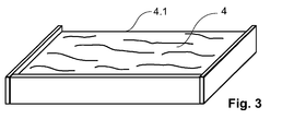
- FIG. 3 In the FIG. 3 is the recording form 1 shown, which was positioned horizontally and the cover plate 1.1 has been removed, so that the upwardly arranged cover surface 4.1 of the green body 4 and is freely accessible.
Landscapes
- Chemical & Material Sciences (AREA)
- Engineering & Computer Science (AREA)
- Ceramic Engineering (AREA)
- Chemical Kinetics & Catalysis (AREA)
- Inorganic Chemistry (AREA)
- Materials Engineering (AREA)
- Structural Engineering (AREA)
- Organic Chemistry (AREA)
- Laminated Bodies (AREA)
Abstract
Description
- Die Erfindung betrifft ein Verfahren zur Herstellung dekorativer Laminate mit schichtartiger, das optische Erscheinungsbild natürlicher Sediment- oder Steinformationen nachahmender Strukturierung aus verfestigten anorganischen Partikeln, wobei die Strukturierung durch künstliche Schüttung der Partikel erreicht wird.
- Die Herstellung von Laminaten, bestehend aus einem Trägermaterial mit einem darauf fixierten Partikelbelag aus Sedimentpartikeln, ist als Technik des Lackabzugs bzw. als Lackfilmmethode bekannt. Diese Methode umfasst die Konservierung von schichtartig strukturierten, geologischen Formationen in lockeren Sedimenten mit Hilfe von Kunstharzen oder Lacken, wobei die schichtartige Strukturierung der Sedimentformation herauspräpariert und auf dem Trägermaterial fixiert wird. Das Kunstharz oder der Lack, im Weiteren allgemein als Haftvermittler bezeichnet, infiltriert die Sedimentformation in einem vorgegebenen Oberflächenabstand, härtet anschließend aus und die Partikel des Sediments haften am Trägermaterial. Das Laminat wird durch Abziehen des auf dem Trägermaterial haftenden, schichtartig strukturierten Partikelbelages hergestellt.
- In
EP 1 268 954 B1 ist die Anwendung der Lackfilmmethode zur Erzeugung dekorativer Laminate aus natürlichen Sedimentformationen beschrieben. Es ist ein Verfahrens offenbart, welches direkt in der Sand- oder Kiesgrube zur Anwendung kommt bzw. als Alternative, nach Verbringung von unveränderten, aus Sand- oder Kiesgruben entnommen Sedimentblöcken, in einen Werkhallenbereich. Beide Verfahren verwenden ausschließlich eine natürliche Sedimentformation als Ausgangsmaterial und sind daher auf diese in der jeweiligen Sand- oder Kiesgrube vorhandene Sedimentformation beschränkt. -
EP 1 268 954 B1 beschreibt auch die Möglichkeit der künstlichen Mischung loser Sande zur Herstellung der Laminate. Dabei wird eine Sandschüttung aus losen Sanden erzeugt und die Laminate werden mittels der Lackfilmmethode direkt an der so erstellten Sandschüttung hergestellt. Im Unterschied zu den natürlichen Sedimentformationen weist die Sandschüttung jedoch keine Eigenfestigkeit auf. Dies ist nachteilig, da die Partikel der Sande ungleichmäßig am Trägermaterial anhaften und folglich keine Laminate mit gleichmäßiger Partikelbelagdicke und -haftung entstehen. Darüber hinaus sind bei künstlicher Mischung der losen Sande mit den in
EP 1 268 954 B1 offenbarten Methoden und Vorrichtungen Laminate, die das optische Erscheinungsbild einer natürlichen, schichtartig strukturierten Sedimentformation aufweisen, nicht herstellbar. - Die Herstellung künstlicher Natursteinimitate als Laminat wird in
GB 1 162 991 A -
WO 2008 022 812 A offenbart die Herstellung eines flexiblen Laminats aus einem mehrlagigen Steinmaterial, dass auf einem Trägermaterial verklebt wird. Das optische Erscheinungsbild des Laminats ist dabei durch die natürliche Strukturierung des Steinmaterials vorgegeben und auf diese beschränkt. - In
EP 2 437 925 B1 ist ein Verfahren zur künstlichen Herstellung von dekorativen Laminaten mittels Lackfilmmethode beschrieben, bei dem eine Sandschüttung erzeugt wird, und diese anschließend zu einem Grünkörper verfestigt wird. Die Strukturierung der Sandschüttung ist bei diesem Verfahren jedoch nicht vorgesehen. Vielmehr ist das Verfahren dadurch charakterisiert, dass die Strukturierung durch nachträgliche Erzeugung von Ausnehmungen im Grünkörper und Ausfüllen derselben mit Kontrastmitteln erreicht wird. Das Laminat wird mittels Lackfilmmethode an dem so präparierten Grünkörper hergestellt. Nachteilig bei dieser Methode ist, dass Laminate, die das optische Erscheinungsbild einer natürlichen, schichtartig strukturierten Sedimentformation aufweisen, nicht herstellbar sind. - Die Herstellung eines Laminats als Natursteinimitat wird des Weiteren in
EP 2 360 025 A2 beschrieben, wobei das Laminat durch künstliches Mischen von fein granuliertem Naturstein mit Schmelzkleber und nachfolgendes Aufbringen auf ein Trägermaterial entsteht. Verfahrensbedingt ist für die erzeugten Produkte die Imitation natürlicher, schichtartiger Strukturierung nicht herstellbar. - Die im Stand der Technik beschriebenen Lösungen zur Herstellung von qualitativ hochwertigen Laminaten mit gleichmäßiger Partikelbelagdicke und -haftung und dem optischen Erscheinungsbild von natürlichen, schichtartig strukturierten Sediment- oder Steinformationen mittels Lackfilmmethode beschränken sich auf Verfahren, die als Ausgangsmaterial natürlich entstandene Sedimentformationen oder Gesteine nutzen.
- Aufgabe der Erfindung ist die Herstellung von Laminaten mit schichtartiger, das optische Erscheinungsbild natürlicher Sediment- oder Steinformationen nachahmender Strukturierung, die durch eine künstliche Schüttung von anorganischen Partikeln erzeugt wird, umfassend ein Trägermaterial und einen darauf fixierten Partikelbelag, der innerhalb jeder Schichtstruktur eine gleichmäßige Partikelbelagdicke und - haftung am Trägermaterial aufweist.
- Die Aufgabe wird gemäß dem Verfahren zur Herstellung dekorativer Laminate mit den Merkmalen nach dem Patentanspruch 1 gelöst; vorteilhafte Weiterbildungen der Erfindung sind in den Unteransprüchen 2-14 beschrieben.
- Erfindungsgemäß werden in einem ersten Schritt des Herstellverfahrens eine Mehrzahl von Mischungen, umfassend eine Vielzahl anorganischer Partikel und ein anorganisches, pulverförmiges, wasserabbindendes Bindemittel hergestellt. Das anorganische, pulverförmige, wasserabbindende Bindemittel wird im Folgenden als Bindemittel bezeichnet. Die für jede der verschiedenen Mischungen verwendeten Partikel unterscheiden sich jeweils in Farbe, Form und/oder Größe.
- Im folgenden Schritt des Verfahrens werden die Mischungen in eine senkrecht aufgestellte, nach oben geöffnete, kastenförmige Aufnahmeform eingefüllt, wobei eine Schüttung erzeugt wird. Die Aufnahmeform ist derart gestaltet, dass deren eine Ausdehnung in horizontaler Richtung deutlich kürzer ist als die beiden anderen Ausdehnungen. Die erste Schichtstruktur der Schüttung entsteht dabei durch das Einfüllen der ersten Mischung. Anschließend wird die zweite Schichtstruktur der Schüttung durch das Einfüllen der zweiten Mischung erzeugt, die z. B. einen anderen Farbton aufweisen kann. Das Einfüllen weiterer Mischungen erfolgt in gleicher Weise bis die Aufnahmeform vollständig gefüllt ist. Durch diese Abfolge des Einfüllens verschiedener Mischungen wird in der Schüttung eine Vielzahl von Schichtstrukturen erzeugt, die in ihrer Gesamtheit die schichtartige Strukturierung bildet. Erfindungsgemäß ist die Schüttung durch Beimengung von Wasser befeuchtet.
- Die Aufnahmeform, enthaltend die Schüttung, wird nach Abschluss des Einfüllvorganges an geeigneter Stelle, z. B. im Bereich einer Werkhalle oder in einem Regal-system, gelagert. Während der Lagerzeit erfolgen eine Trocknung und eine Aushärtung der Schüttung zu einem plattenförmigen Grünkörper durch Abbindung des Bindemittels mit dem beigemengten Wasser. Beim Aushärten wird im Grünkörper ein offenporiger Verbund der anorganischen Partikel gebildet, wobei dieser Verbund durch eine Zugfestigkeit von 0,5 bis 10 MPa, d. h. in der Größenordnung von natürlich gewachsenen Sedimentformationen, und eine weitgehend gleichmäßige Bindung der anorganischen Partikel untereinander charakterisiert ist. Die beiden Deckflächen des plattenförmigen Grünkörpers weisen die schichtartige Strukturierung auf.
- Die Aufnahmeform mit dem Grünkörper wird anschließend waagerecht so positioniert, dass eine der Deckflächen des Grünkörpers nach oben gerichtet ist. Die Deckplatte der Aufnahmeform, die die nach oben gerichtete Deckfläche des Grünkörpers abdeckt, wird entfernt, und die obere Deckfläche des Grünkörpers wird dadurch frei zugänglich.
- Auf diese Deckfläche des Grünkörpers wird nach dessen Glättung ein bahnartiges Trägermaterial, z. B. ein Gewebe oder ein Vließ, aufgelegt und darauf ein flüssiger Haftvermittler durch Gießen, Tränken, Streichen, Rollen, Sprühen oder vergleichbare Verfahren aufgetragen. Dabei wird der Grünkörper in einem vorgegebenen Oberflächenabstand durch den Haftvermittler penetriert. Anschließend erfolgt die Aushärtung des Haftvermittlers, wobei sich ein am Trägermaterial anhaftender Partikelbelag bildet.
- Im letzten Schritt des Verfahrens wird das Trägermaterial mit dem daran anhaftenden Partikelbelag vom Grünkörper abgehoben und dabei das Laminat gebildet.
- Der Vorgang des Glättens, Aufbringens des Trägermaterials und des Haftvermittlers, die Aushärtung und das Abheben kann am Grünkörper mehrfach wiederholt werden, sodass eine Vielzahl von Laminatbahnen an ein und demselben Grünkörper erzeugt werden können.
- Der Vorteil der Erfindung besteht darin, dass das Einbringen der Mehrzahl von Mischungen mit unterschiedlichen optischen Eigenschaften durch das Einfüllen in die Aufnahmeform derart durchgeführt werden kann, dass die schichtartige Strukturierung der entstandenen Schüttung und folglich des Laminats dem optischen Erscheinungsbild von natürlichen Sedimentformationen in Sand- oder Kiesgruben entspricht. Die künstliche Auswahl und die künstliche Einbringung der verwendeten Mischungen bieten darüber hinaus den Vorteil einer deutlichen Erweiterung der Farbgebung und der Akzentuierung in Bezug auf die optische Gestaltung des Laminats.
- Ein weiterer Vorteil der Erfindung ist die Erzeugung des Grünkörpers mit der Zugfestigkeit 0,5 bis 10 MPa als Zwischenschritt im Verfahren. Aufgrund der gezielten Herstellung des offenporigen Verbundes der anorganischen Partikel im Grünkörper wird im nachfolgenden Verfahrensschritt, dem Aufbringen des Haftvermittlers, erreicht, dass dieser den Grünkörper im gesamten Flächenbereich jeder einzelnen Schichtstruktur in gleichem Oberflächenabstand penetriert. Ebenso bewirkt die weitgehend gleichmäßige Bindung der anorganischen Partikel untereinander, dass beim Abheben des am Trägermaterial anhaftenden Partikelbelages vom Grünkörper dieser sich im gesamten Flächenbereich jeder Schichtstruktur mit gleicher Partikelbelagdicke ablösen lässt.
- Es kann vorgesehen sein, dass die Schüttung entweder durch Einbringen von Mischungen in die Aufnahmeform, denen zuvor Wasser beigemengt wurde, oder nachträglich befeuchtet wird. Hierdurch kann die Rieselfähigkeit der Mischungen ebenso wie das Setzen der Schüttung beeinflusst werden, wobei damit wiederum Laminate mit unterschiedlichen optischen Effekten hergestellt werden können.
- Vorteilhaft können als anorganische Partikel gemahlene, natürliche Mineralstoffe verwendet werden, z. B. Sand, Ton, Lehm und/oder Steinkohlenstaub, da diese gut verfügbar und gleichzeitig kostengünstig sind. Dies gilt insbesondere für die Mischungen auf Basis von Sanden, weshalb diese mit Vorteil als mengenmäßig größter Anteil zur Herstellung der Laminate eingesetzt werden.
- Ferner kann als Bindemittel ein Zement, Gips oder Kalkmörtel verwendet werden. Diese Bindemittel sind ebenso gut verfügbar und kostengünstig.
- Gemäß einer Ausführungsform kann die jeweilige Mischung durch Mischen der anorganischen Partikel mit einem Mengenanteil von 1 bis 2 Gew.-% Bindemittel, z. B. Zement, hergestellt werden. In Verbindung mit dieser Ausführungsform werden vorteilhaft 5 bis 10 Gew.-% Wasser zur Mischung oder Schüttung zugegeben. Dadurch wird für die aus der jeweiligen Mischung erzeugte Schichtstruktur erreicht, dass nach der Trocknung und der Aushärtung diese die Zugfestigkeit von 0,5 bis 10 MPa aufweist. Dies wiederum bewirkt, dass der Haftvermittler den Grünkörper in der jeweiligen Schichtstruktur in gleichmäßigem Oberflächenabstand penetriert und sich folglich für jede Schichtstruktur am Laminat eine gleichmäßige Partikelbelagdicke und - haftung ausbildet. Durch Variation der Zugabe des Bindemittels kann die Partikelbelagdicke so eingestellt werden, dass diese in allen Schichtstrukturen identisch ist, wobei das gesamte Laminat in diesem Fall mit einheitlicher Dicke erzeugt wird. Alternativ kann die Bindemittelzugabe in den verschiedenen Mischungen so gesteuert werden, dass die Penetration des Haftvermittlers in den Grünkörper für verschiedene Schichtstrukturen in unterschiedlichem Oberflächenabstand erfolgt und damit das Laminat beim Abheben unterschiedliche Partikelbelagdicken für die verschiedenen Schichtstrukturen aufweist. Dies ermöglicht neben der farblichen Strukturierung des Laminats zusätzlich die Herstellung eines Reliefeffektes.
- In einer Ausbildung der Erfindung kann das Verfahren so durchgeführt werden, dass die Aufnahmeform nach dem Aushärten der Schüttung und der Entstehung des Grünkörpers entfernt und somit eine Arbeitsbehinderung durch die vorhandene Aufnahmeform beim Aufbringen des Trägermaterials vermieden wird. Darüber hinaus bietet dies den Vorteil, dass die Aufnahmeform oder Teile derselben der Wiederverwendung zugeführt werden können.
- Gemäß der Erfindung kann vorgesehen sein, die Aufnahmeform mit einer Deckplatte aus transparentem Material zu verwenden. Dies ermöglicht während des Einfüllvorganges die Qualitätskontrolle in Bezug auf das optische Erscheinungsbild der schichtartigen Strukturierung der Schüttung.
- In einer Ausbildung der Erfindung kann der Haftvermittler aus Material sein, welches unter ultraviolettem Licht aushärtet. Dies verringert die Abhängigkeit der Aushärtung von Umgebungsbedingungen wie Temperatur und Luftfeuchte und führt zu einer Verkürzung der Prozesszeiten.
- Weiterhin können anorganische Partikel mit funktionalen Eigenschaften in die dekorativen Laminate eingebracht werden. Eine solche Funktion kann die Schirmung elektrischer Felder zur Verbesserung der elektromagnetischen Verträglichkeit sein, wobei hierfür vorteilhaft weichferritische Partikel, wie Mangan-Zink-Ferrite oder Nickel-Zink-Ferrite, verwendet werden. Durch Einbringen hartferritischer Partikel, wie z. B. Strontium-Ferrite, Barium-Ferrite oder Cobalt-Ferrite, können Hafteigenschaften für Dauermagnete erzeugt werden. Eine antibakterielle Wirkung und das Verringern von Algen- und Moosbefall kann mit Vorteil durch Verwendung von Kupfer- und Silberpartikeln erreicht werden.
- Die Erfindung wird nachfolgend anhand eines Ausführungsbeispiels und mit Bezug auf die schematischen Zeichnungen näher erläutert. Dazu zeigen
- Fig. 1:
- die kastenförmige Aufnahmeform beim Vorgang des Einfüllens,
- Fig. 2:
- den Grünkörper in der Aufnahmeform, und
- Fig. 3:
- den Grünkörper nach dem waagerechten Positionieren und Entfernen der oberen Deckplatte.
- In der
Figur 1 ist die kastenförmige Aufnahmeform 1 mit den Seitenwänden 1.2 dargestellt. In die nach oben angeordnete Einfüllöffnung 1.3 der Aufnahmeform 1 wird die Mischung 3 aus den anorganischen Partikeln und dem Bindemittel eingefüllt. Die Prozesskontrolle erfolgt durch die Verwendung der transparenten Deckplatte 1.1 der Aufnahmeform 1. - Die
Figur 2 zeigt die Aufnahmeform 1, enthaltend den Grünkörper 4, nach Abschluss des Einfüllvorganges und der Aushärtung. - In der
Figur 3 ist die Aufnahmeform 1 dargestellt, wobei diese waagerecht positioniert und die Deckplatte 1.1 entfernt wurde, sodass die nach oben angeordnete Deckfläche 4.1 des Grünkörpers 4 und frei zugänglich ist. -
- 1
- Aufnahmeform
- 1.1
- Deckplatte der Aufnahmeform
- 1.2
- Seitenwand der Aufnahmeform
- 1.3
- Einfüllöffnung der Aufnahmeform
- 2
- Schüttung
- 3
- Mischung
- 4
- Grünkörper
- 4.1
- Deckfläche des Grünkörpers
Claims (14)
- Verfahren zur Herstellung dekorativer Laminate aus verfestigten anorganischen Partikeln, wobei die Partikel nach Maßgabe einer angestrebten schichtartigen Strukturierung auf einem Trägermaterial fixiert werden,
gekennzeichnet durch folgende Verfahrensschritte:a) Herstellen einer Mehrzahl von Mischungen (3), jeweils aufweisend eine Vielzahl anorganischer Partikel und ein anorganisches, pulverförmiges, wasserabbindendes Bindemittel, wobei für die unterschiedlichen Mischungen (3) jeweils anorganische Partikel unterschiedlicher Farbgebung, Partikelgröße und/oder -form verwendet werden,b) Herstellen einer feuchten Schüttung (2), aufweisend die schichtartige Strukturierung, wobei ein abwechselndes Einfüllen der Mischungen (3) in eine kastenförmige, senkrecht aufgestellte, nach oben geöffnete Aufnahmeform (1), deren eine Ausdehnung in horizontaler Richtung deutlich kürzer ist als die beiden anderen Ausdehnungen, erfolgt,c) Trocknen und Aushärten der Schüttung (2) unter Ausbildung eines plattenförmigen Grünkörpers (4), wobei die beiden Deckflächen des Grünkörpers (4) die schichtartige Strukturierung aufweisen,d) waagerechtes Positionieren der Aufnahmeform (1) mit dem Grünkörper (4) und Entfernen der oberen Deckplatte (1.1),e) Auflegen eines bahnartigen Trägermaterials auf die obere Deckfläche (4.1) des plattenförmigen Grünkörpers (4),f) Aufbringen eines, das bahnartige Trägermaterial und den Grünkörper (4) in vorgegebenem Oberflächenabstand penetrierenden, flüssigen Haftvermittlers,g) Aushärten des Haftvermittlers unter Ausbildung eines am Trägermaterial haftenden Partikelbelages, undh) Abheben des Trägermaterials mit dem daran haftenden Partikelbelag vom Grünkörper (4) unter Ausbildung des Laminates mit der schichtartigen Strukturierung. - Verfahren nach Anspruch 1, dadurch gekennzeichnet, dass das Herstellen der feuchten Schüttung (2) durch Einfüllen von befeuchteten Mischungen (3) erfolgt.
- Verfahren nach Anspruch 1, dadurch gekennzeichnet, dass das Herstellen der feuchten Schüttung (2) durch Einfüllen von trockenen Mischungen (3) und anschließendem Befeuchten erfolgt.
- Verfahren nach einem der Ansprüche 1 bis 3, dadurch gekennzeichnet, dass als anorganische Partikel gemahlene, natürliche Mineralstoffe verwendet werden.
- Verfahren nach Anspruch 4, dadurch gekennzeichnet, dass als gemahlener, natürlicher Mineralstoff Sand, Ton, Lehm und/oder Steinkohlenstaub verwendet wird.
- Verfahren nach einem der Ansprüche 1 bis 5, dadurch gekennzeichnet, dass als anorganisches, pulverförmiges, wasserabbindendes Bindemittel Zement, Gips oder Kalkmörtel verwendet wird.
- Verfahren nach einem der Ansprüche 1 bis 6, dadurch gekennzeichnet, dass die Mischungen (3) jeweils einen Mengenanteil von 1 bis 2 Gew.-% anorganisches, pulverförmiges, wasserabbindendes Bindemittel aufweisen.
- Verfahren nach einem der Ansprüche 1 bis 7, dadurch gekennzeichnet, dass die Schüttung (2) durch Zugabe einer Wassermenge von 5 bis 10 Gew.-% der Schüttungsmasse befeuchtet wird.
- Verfahren nach einem der Ansprüche 1 bis 8, dadurch gekennzeichnet, dass eine zerlegbare, plattenförmige Aufnahmeform (1) verwendet wird, wobei die Seitenwände (1.2) der Aufnahmeform (1) nach dem Aushärten des Grünkörpers (4) entfernt oder um 90° abgeklappt werden.
- Verfahren nach einem der Ansprüche 1 bis 9, dadurch gekennzeichnet, dass eine Aufnahmeform (1) mit einer transparenten Deckplatte (1.1) verwendet wird.
- Verfahren nach einem der Ansprüche 1 bis 10, dadurch gekennzeichnet, dass der Haftvermittler UV-sensitiv ist, wobei er durch UV-Beleuchtung ausgehärtet wird.
- Verfahren nach einem der Ansprüche 1 bis 11, dadurch gekennzeichnet, dass in eine oder mehre Mischungen (3) Weichferritpartikel, wie Mangan-Zink-Ferrite oder Nickel-Zink-Ferrite, eingebracht werden.
- Verfahren nach einem der Ansprüche 1 bis 11, dadurch gekennzeichnet, dass in eine oder mehre Mischungen (3) Hartferritpartikel, wie Strontium-Ferrite, Barium-Ferrite oder Cobalt-Ferrite, eingebracht werden.
- Verfahren nach einem der Ansprüche 1 bis 13, dadurch gekennzeichnet, dass in eine oder mehre Mischungen (3) Partikel aus Kupfer oder Silber eingebracht werden.
Applications Claiming Priority (2)
| Application Number | Priority Date | Filing Date | Title |
|---|---|---|---|
| DE102015107184 | 2015-05-08 | ||
| DE102015113043 | 2015-08-07 |
Publications (3)
| Publication Number | Publication Date |
|---|---|
| EP3090883A2 true EP3090883A2 (de) | 2016-11-09 |
| EP3090883A3 EP3090883A3 (de) | 2017-05-03 |
| EP3090883B1 EP3090883B1 (de) | 2018-08-22 |
Family
ID=56131286
Family Applications (1)
| Application Number | Title | Priority Date | Filing Date |
|---|---|---|---|
| EP16167916.2A Not-in-force EP3090883B1 (de) | 2015-05-08 | 2016-05-02 | Verfahren zur herstellung dekorativer laminate |
Country Status (1)
| Country | Link |
|---|---|
| EP (1) | EP3090883B1 (de) |
Citations (5)
| Publication number | Priority date | Publication date | Assignee | Title |
|---|---|---|---|---|
| GB1162991A (en) | 1966-07-13 | 1969-09-04 | Frederick Haydon | Artstone |
| WO2008022812A1 (de) | 2006-08-24 | 2008-02-28 | Gernot Ehrlich | Flexibles flachmaterial mit natursteinoberfläche |
| EP2360025A2 (de) | 2010-02-23 | 2011-08-24 | Oxiegen GmbH | Abdeckbahn zur Imitation von Naturstein |
| EP1268954B1 (de) | 2000-03-31 | 2013-01-23 | Neupert, Dieter, Dr. | Arbeitsverfahren zur Herstellung von dekorativen Schichtbahnen mit verfestigten Sandschichten und zum Aufbringen der Schichtbahnen auf Wände, Decken oder Böden, Vorrichtung zur Durchführung dieses Verfahrens und Wände, Decken oder Böden versehen mit solchen Schichtbahnen |
| EP2437925B1 (de) | 2009-06-02 | 2013-07-31 | Holger Marohn | Verfahren zum herstellen eines sichtbelags |
Family Cites Families (3)
| Publication number | Priority date | Publication date | Assignee | Title |
|---|---|---|---|---|
| US1570538A (en) * | 1925-03-24 | 1926-01-19 | Thomas James | Method of making artificial stone |
| DE2330005A1 (de) * | 1973-06-13 | 1975-01-09 | Peter Rast | Herstellungsverfahren von ziersteinen und plastiken |
| US9186819B1 (en) * | 2014-08-19 | 2015-11-17 | Cambria Company Llc | Synthetic molded slabs, and systems and methods related thereto |
-
2016
- 2016-05-02 EP EP16167916.2A patent/EP3090883B1/de not_active Not-in-force
Patent Citations (5)
| Publication number | Priority date | Publication date | Assignee | Title |
|---|---|---|---|---|
| GB1162991A (en) | 1966-07-13 | 1969-09-04 | Frederick Haydon | Artstone |
| EP1268954B1 (de) | 2000-03-31 | 2013-01-23 | Neupert, Dieter, Dr. | Arbeitsverfahren zur Herstellung von dekorativen Schichtbahnen mit verfestigten Sandschichten und zum Aufbringen der Schichtbahnen auf Wände, Decken oder Böden, Vorrichtung zur Durchführung dieses Verfahrens und Wände, Decken oder Böden versehen mit solchen Schichtbahnen |
| WO2008022812A1 (de) | 2006-08-24 | 2008-02-28 | Gernot Ehrlich | Flexibles flachmaterial mit natursteinoberfläche |
| EP2437925B1 (de) | 2009-06-02 | 2013-07-31 | Holger Marohn | Verfahren zum herstellen eines sichtbelags |
| EP2360025A2 (de) | 2010-02-23 | 2011-08-24 | Oxiegen GmbH | Abdeckbahn zur Imitation von Naturstein |
Also Published As
| Publication number | Publication date |
|---|---|
| EP3090883A3 (de) | 2017-05-03 |
| EP3090883B1 (de) | 2018-08-22 |
Similar Documents
| Publication | Publication Date | Title |
|---|---|---|
| EP0417164B1 (de) | Kunststeine, verfahren zur herstellung und verwendung derselben | |
| EP3166904B1 (de) | Verfahren zum herstellen von betonelementen | |
| DE4137463C2 (de) | Verfahren zur Herstellung von Naturstein-Imitationen, insbesondere großvolumiger Felsblock-Imitationen | |
| DE102013020491A1 (de) | 3D-Infiltrationsverfahren | |
| DE3041794A1 (de) | Verfahren zum herstellen von dessinierten formkoerpern aus einer haertbaren masse auf basis duroplastischer kunststoffe | |
| EP3630433B1 (de) | Verfahren zur herstellung eines bedruckten betonelements | |
| DE102013101521B4 (de) | Flächenelement mit aufgebrachtem Dekor und Verfahren zur Herstellung des Flächenelementes | |
| DE1300862B (de) | Verfahren und Form zur Herstellung von Kunstmarmor-Elementen | |
| DE102015122418B4 (de) | Verfahren zur Herstellung dekorativer Laminate | |
| EP3090883B1 (de) | Verfahren zur herstellung dekorativer laminate | |
| DE102007014496B3 (de) | Verlegware und ein Verfahren zur Herstellung einer solchen | |
| WO2024083943A1 (de) | Verfahren und vorrichtung zur herstellung eines bedruckten betonkörpers, sowie bedruckter betonkörper | |
| WO2024083944A1 (de) | Verfahren und vorrichtung zur herstellung eines bedruckten betonkörpers, sowie bedruckter betonkörper | |
| DE10146408A1 (de) | Quarz-Farbkorn und Verfahren zur Herstellung | |
| WO2017029325A1 (de) | Magnet-holz-verbundwerkstoff | |
| WO2022199850A1 (de) | Verfahren zum herstellen eines betonelements | |
| DE3128592C2 (de) | ||
| DE1671289C3 (de) | Verfahren zum Aufbringen von Granulat auf Teile der Oberfläche von Porenbetonkörpern | |
| DE202006020340U1 (de) | Kunststeinformkörper | |
| DE19725088C2 (de) | Verfahren zum Herstellen eines Pflastersteins | |
| DE1479143C3 (de) | Verfahren zur Herstellung von Kunststoffplatten für Wandbeläge | |
| DE10305056A1 (de) | Verfahren zur technischen Herstellung von Betonwaren mit nachgebildeten Naturstein- oder sonstigen ästhetisch gestalteten Oberflächen | |
| DE102011085768A1 (de) | Farbiges, mineralisches Material sowie die Verwendung und das Verfahren zur Herstellung desselben | |
| DE10250242A1 (de) | Verfahren zum Herstellen eines Dekomaterials sowie Dekomaterial hergestellt nach diesem Verfahren | |
| DE202005018993U1 (de) | Vorrichtung zur Herstellung von glänzenden Betonflächen |
Legal Events
| Date | Code | Title | Description |
|---|---|---|---|
| PUAI | Public reference made under article 153(3) epc to a published international application that has entered the european phase |
Free format text: ORIGINAL CODE: 0009012 |
|
| AK | Designated contracting states |
Kind code of ref document: A2 Designated state(s): AL AT BE BG CH CY CZ DE DK EE ES FI FR GB GR HR HU IE IS IT LI LT LU LV MC MK MT NL NO PL PT RO RS SE SI SK SM TR |
|
| AX | Request for extension of the european patent |
Extension state: BA ME |
|
| PUAL | Search report despatched |
Free format text: ORIGINAL CODE: 0009013 |
|
| AK | Designated contracting states |
Kind code of ref document: A3 Designated state(s): AL AT BE BG CH CY CZ DE DK EE ES FI FR GB GR HR HU IE IS IT LI LT LU LV MC MK MT NL NO PL PT RO RS SE SI SK SM TR |
|
| AX | Request for extension of the european patent |
Extension state: BA ME |
|
| RIC1 | Information provided on ipc code assigned before grant |
Ipc: B44C 5/04 20060101AFI20170329BHEP Ipc: E04F 13/08 20060101ALI20170329BHEP Ipc: C04B 14/00 20060101ALI20170329BHEP Ipc: B44F 9/04 20060101ALI20170329BHEP Ipc: B28B 1/00 20060101ALI20170329BHEP |
|
| STAA | Information on the status of an ep patent application or granted ep patent |
Free format text: STATUS: REQUEST FOR EXAMINATION WAS MADE |
|
| 17P | Request for examination filed |
Effective date: 20171026 |
|
| RBV | Designated contracting states (corrected) |
Designated state(s): AL AT BE BG CH CY CZ DE DK EE ES FI FR GB GR HR HU IE IS IT LI LT LU LV MC MK MT NL NO PL PT RO RS SE SI SK SM TR |
|
| GRAP | Despatch of communication of intention to grant a patent |
Free format text: ORIGINAL CODE: EPIDOSNIGR1 |
|
| STAA | Information on the status of an ep patent application or granted ep patent |
Free format text: STATUS: GRANT OF PATENT IS INTENDED |
|
| RIC1 | Information provided on ipc code assigned before grant |
Ipc: E04F 13/08 20060101ALI20180219BHEP Ipc: B28B 1/00 20060101ALI20180219BHEP Ipc: C04B 14/00 20060101ALI20180219BHEP Ipc: B44F 9/04 20060101ALI20180219BHEP Ipc: B44C 5/04 20060101AFI20180219BHEP |
|
| INTG | Intention to grant announced |
Effective date: 20180309 |
|
| GRAS | Grant fee paid |
Free format text: ORIGINAL CODE: EPIDOSNIGR3 |
|
| GRAA | (expected) grant |
Free format text: ORIGINAL CODE: 0009210 |
|
| STAA | Information on the status of an ep patent application or granted ep patent |
Free format text: STATUS: THE PATENT HAS BEEN GRANTED |
|
| AK | Designated contracting states |
Kind code of ref document: B1 Designated state(s): AL AT BE BG CH CY CZ DE DK EE ES FI FR GB GR HR HU IE IS IT LI LT LU LV MC MK MT NL NO PL PT RO RS SE SI SK SM TR |
|
| REG | Reference to a national code |
Ref country code: GB Ref legal event code: FG4D Free format text: NOT ENGLISH |
|
| REG | Reference to a national code |
Ref country code: CH Ref legal event code: EP |
|
| REG | Reference to a national code |
Ref country code: AT Ref legal event code: REF Ref document number: 1032008 Country of ref document: AT Kind code of ref document: T Effective date: 20180915 |
|
| REG | Reference to a national code |
Ref country code: IE Ref legal event code: FG4D Free format text: LANGUAGE OF EP DOCUMENT: GERMAN |
|
| REG | Reference to a national code |
Ref country code: DE Ref legal event code: R096 Ref document number: 502016001736 Country of ref document: DE |
|
| REG | Reference to a national code |
Ref country code: NL Ref legal event code: MP Effective date: 20180822 |
|
| REG | Reference to a national code |
Ref country code: LT Ref legal event code: MG4D |
|
| PG25 | Lapsed in a contracting state [announced via postgrant information from national office to epo] |
Ref country code: FI Free format text: LAPSE BECAUSE OF FAILURE TO SUBMIT A TRANSLATION OF THE DESCRIPTION OR TO PAY THE FEE WITHIN THE PRESCRIBED TIME-LIMIT Effective date: 20180822 Ref country code: LT Free format text: LAPSE BECAUSE OF FAILURE TO SUBMIT A TRANSLATION OF THE DESCRIPTION OR TO PAY THE FEE WITHIN THE PRESCRIBED TIME-LIMIT Effective date: 20180822 Ref country code: GR Free format text: LAPSE BECAUSE OF FAILURE TO SUBMIT A TRANSLATION OF THE DESCRIPTION OR TO PAY THE FEE WITHIN THE PRESCRIBED TIME-LIMIT Effective date: 20181123 Ref country code: SE Free format text: LAPSE BECAUSE OF FAILURE TO SUBMIT A TRANSLATION OF THE DESCRIPTION OR TO PAY THE FEE WITHIN THE PRESCRIBED TIME-LIMIT Effective date: 20180822 Ref country code: BG Free format text: LAPSE BECAUSE OF FAILURE TO SUBMIT A TRANSLATION OF THE DESCRIPTION OR TO PAY THE FEE WITHIN THE PRESCRIBED TIME-LIMIT Effective date: 20181122 Ref country code: NO Free format text: LAPSE BECAUSE OF FAILURE TO SUBMIT A TRANSLATION OF THE DESCRIPTION OR TO PAY THE FEE WITHIN THE PRESCRIBED TIME-LIMIT Effective date: 20181122 Ref country code: NL Free format text: LAPSE BECAUSE OF FAILURE TO SUBMIT A TRANSLATION OF THE DESCRIPTION OR TO PAY THE FEE WITHIN THE PRESCRIBED TIME-LIMIT Effective date: 20180822 Ref country code: RS Free format text: LAPSE BECAUSE OF FAILURE TO SUBMIT A TRANSLATION OF THE DESCRIPTION OR TO PAY THE FEE WITHIN THE PRESCRIBED TIME-LIMIT Effective date: 20180822 Ref country code: IS Free format text: LAPSE BECAUSE OF FAILURE TO SUBMIT A TRANSLATION OF THE DESCRIPTION OR TO PAY THE FEE WITHIN THE PRESCRIBED TIME-LIMIT Effective date: 20181222 |
|
| PG25 | Lapsed in a contracting state [announced via postgrant information from national office to epo] |
Ref country code: HR Free format text: LAPSE BECAUSE OF FAILURE TO SUBMIT A TRANSLATION OF THE DESCRIPTION OR TO PAY THE FEE WITHIN THE PRESCRIBED TIME-LIMIT Effective date: 20180822 Ref country code: AL Free format text: LAPSE BECAUSE OF FAILURE TO SUBMIT A TRANSLATION OF THE DESCRIPTION OR TO PAY THE FEE WITHIN THE PRESCRIBED TIME-LIMIT Effective date: 20180822 Ref country code: LV Free format text: LAPSE BECAUSE OF FAILURE TO SUBMIT A TRANSLATION OF THE DESCRIPTION OR TO PAY THE FEE WITHIN THE PRESCRIBED TIME-LIMIT Effective date: 20180822 |
|
| PG25 | Lapsed in a contracting state [announced via postgrant information from national office to epo] |
Ref country code: ES Free format text: LAPSE BECAUSE OF FAILURE TO SUBMIT A TRANSLATION OF THE DESCRIPTION OR TO PAY THE FEE WITHIN THE PRESCRIBED TIME-LIMIT Effective date: 20180822 Ref country code: IT Free format text: LAPSE BECAUSE OF FAILURE TO SUBMIT A TRANSLATION OF THE DESCRIPTION OR TO PAY THE FEE WITHIN THE PRESCRIBED TIME-LIMIT Effective date: 20180822 Ref country code: RO Free format text: LAPSE BECAUSE OF FAILURE TO SUBMIT A TRANSLATION OF THE DESCRIPTION OR TO PAY THE FEE WITHIN THE PRESCRIBED TIME-LIMIT Effective date: 20180822 Ref country code: CZ Free format text: LAPSE BECAUSE OF FAILURE TO SUBMIT A TRANSLATION OF THE DESCRIPTION OR TO PAY THE FEE WITHIN THE PRESCRIBED TIME-LIMIT Effective date: 20180822 Ref country code: EE Free format text: LAPSE BECAUSE OF FAILURE TO SUBMIT A TRANSLATION OF THE DESCRIPTION OR TO PAY THE FEE WITHIN THE PRESCRIBED TIME-LIMIT Effective date: 20180822 Ref country code: PL Free format text: LAPSE BECAUSE OF FAILURE TO SUBMIT A TRANSLATION OF THE DESCRIPTION OR TO PAY THE FEE WITHIN THE PRESCRIBED TIME-LIMIT Effective date: 20180822 |
|
| REG | Reference to a national code |
Ref country code: DE Ref legal event code: R097 Ref document number: 502016001736 Country of ref document: DE |
|
| PG25 | Lapsed in a contracting state [announced via postgrant information from national office to epo] |
Ref country code: DK Free format text: LAPSE BECAUSE OF FAILURE TO SUBMIT A TRANSLATION OF THE DESCRIPTION OR TO PAY THE FEE WITHIN THE PRESCRIBED TIME-LIMIT Effective date: 20180822 Ref country code: SK Free format text: LAPSE BECAUSE OF FAILURE TO SUBMIT A TRANSLATION OF THE DESCRIPTION OR TO PAY THE FEE WITHIN THE PRESCRIBED TIME-LIMIT Effective date: 20180822 Ref country code: SM Free format text: LAPSE BECAUSE OF FAILURE TO SUBMIT A TRANSLATION OF THE DESCRIPTION OR TO PAY THE FEE WITHIN THE PRESCRIBED TIME-LIMIT Effective date: 20180822 |
|
| PLBE | No opposition filed within time limit |
Free format text: ORIGINAL CODE: 0009261 |
|
| STAA | Information on the status of an ep patent application or granted ep patent |
Free format text: STATUS: NO OPPOSITION FILED WITHIN TIME LIMIT |
|
| 26N | No opposition filed |
Effective date: 20190523 |
|
| PG25 | Lapsed in a contracting state [announced via postgrant information from national office to epo] |
Ref country code: SI Free format text: LAPSE BECAUSE OF FAILURE TO SUBMIT A TRANSLATION OF THE DESCRIPTION OR TO PAY THE FEE WITHIN THE PRESCRIBED TIME-LIMIT Effective date: 20180822 |
|
| REG | Reference to a national code |
Ref country code: DE Ref legal event code: R119 Ref document number: 502016001736 Country of ref document: DE |
|
| REG | Reference to a national code |
Ref country code: CH Ref legal event code: PL |
|
| PG25 | Lapsed in a contracting state [announced via postgrant information from national office to epo] |
Ref country code: LI Free format text: LAPSE BECAUSE OF NON-PAYMENT OF DUE FEES Effective date: 20190531 Ref country code: CH Free format text: LAPSE BECAUSE OF NON-PAYMENT OF DUE FEES Effective date: 20190531 Ref country code: MC Free format text: LAPSE BECAUSE OF FAILURE TO SUBMIT A TRANSLATION OF THE DESCRIPTION OR TO PAY THE FEE WITHIN THE PRESCRIBED TIME-LIMIT Effective date: 20180822 |
|
| REG | Reference to a national code |
Ref country code: BE Ref legal event code: MM Effective date: 20190531 |
|
| PG25 | Lapsed in a contracting state [announced via postgrant information from national office to epo] |
Ref country code: LU Free format text: LAPSE BECAUSE OF NON-PAYMENT OF DUE FEES Effective date: 20190502 |
|
| PG25 | Lapsed in a contracting state [announced via postgrant information from national office to epo] |
Ref country code: TR Free format text: LAPSE BECAUSE OF FAILURE TO SUBMIT A TRANSLATION OF THE DESCRIPTION OR TO PAY THE FEE WITHIN THE PRESCRIBED TIME-LIMIT Effective date: 20180822 |
|
| PG25 | Lapsed in a contracting state [announced via postgrant information from national office to epo] |
Ref country code: DE Free format text: LAPSE BECAUSE OF NON-PAYMENT OF DUE FEES Effective date: 20191203 Ref country code: IE Free format text: LAPSE BECAUSE OF NON-PAYMENT OF DUE FEES Effective date: 20190502 |
|
| PG25 | Lapsed in a contracting state [announced via postgrant information from national office to epo] |
Ref country code: BE Free format text: LAPSE BECAUSE OF NON-PAYMENT OF DUE FEES Effective date: 20190531 |
|
| PG25 | Lapsed in a contracting state [announced via postgrant information from national office to epo] |
Ref country code: FR Free format text: LAPSE BECAUSE OF NON-PAYMENT OF DUE FEES Effective date: 20190531 Ref country code: PT Free format text: LAPSE BECAUSE OF FAILURE TO SUBMIT A TRANSLATION OF THE DESCRIPTION OR TO PAY THE FEE WITHIN THE PRESCRIBED TIME-LIMIT Effective date: 20181222 |
|
| GBPC | Gb: european patent ceased through non-payment of renewal fee |
Effective date: 20200502 |
|
| PG25 | Lapsed in a contracting state [announced via postgrant information from national office to epo] |
Ref country code: GB Free format text: LAPSE BECAUSE OF NON-PAYMENT OF DUE FEES Effective date: 20200502 |
|
| PG25 | Lapsed in a contracting state [announced via postgrant information from national office to epo] |
Ref country code: CY Free format text: LAPSE BECAUSE OF FAILURE TO SUBMIT A TRANSLATION OF THE DESCRIPTION OR TO PAY THE FEE WITHIN THE PRESCRIBED TIME-LIMIT Effective date: 20180822 |
|
| PG25 | Lapsed in a contracting state [announced via postgrant information from national office to epo] |
Ref country code: HU Free format text: LAPSE BECAUSE OF FAILURE TO SUBMIT A TRANSLATION OF THE DESCRIPTION OR TO PAY THE FEE WITHIN THE PRESCRIBED TIME-LIMIT; INVALID AB INITIO Effective date: 20160502 Ref country code: MT Free format text: LAPSE BECAUSE OF FAILURE TO SUBMIT A TRANSLATION OF THE DESCRIPTION OR TO PAY THE FEE WITHIN THE PRESCRIBED TIME-LIMIT Effective date: 20180822 |
|
| PG25 | Lapsed in a contracting state [announced via postgrant information from national office to epo] |
Ref country code: MK Free format text: LAPSE BECAUSE OF FAILURE TO SUBMIT A TRANSLATION OF THE DESCRIPTION OR TO PAY THE FEE WITHIN THE PRESCRIBED TIME-LIMIT Effective date: 20180822 |
|
| REG | Reference to a national code |
Ref country code: AT Ref legal event code: MM01 Ref document number: 1032008 Country of ref document: AT Kind code of ref document: T Effective date: 20210502 |
|
| PG25 | Lapsed in a contracting state [announced via postgrant information from national office to epo] |
Ref country code: AT Free format text: LAPSE BECAUSE OF NON-PAYMENT OF DUE FEES Effective date: 20210502 |