EP3090915A1 - Chariot de transport pour copeaux de bois - Google Patents
Chariot de transport pour copeaux de bois Download PDFInfo
- Publication number
- EP3090915A1 EP3090915A1 EP16168455.0A EP16168455A EP3090915A1 EP 3090915 A1 EP3090915 A1 EP 3090915A1 EP 16168455 A EP16168455 A EP 16168455A EP 3090915 A1 EP3090915 A1 EP 3090915A1
- Authority
- EP
- European Patent Office
- Prior art keywords
- trolley
- load
- container
- side wall
- cargo container
- Prior art date
- Legal status (The legal status is an assumption and is not a legal conclusion. Google has not performed a legal analysis and makes no representation as to the accuracy of the status listed.)
- Withdrawn
Links
- 239000002023 wood Substances 0.000 title abstract description 8
- 238000005192 partition Methods 0.000 claims abstract description 20
- 238000000034 method Methods 0.000 description 11
- 230000004888 barrier function Effects 0.000 description 7
- 238000013016 damping Methods 0.000 description 1
- 238000011161 development Methods 0.000 description 1
- 230000018109 developmental process Effects 0.000 description 1
- 230000005611 electricity Effects 0.000 description 1
- 230000003137 locomotive effect Effects 0.000 description 1
- 239000000463 material Substances 0.000 description 1
Images


Classifications
-
- B—PERFORMING OPERATIONS; TRANSPORTING
- B61—RAILWAYS
- B61D—BODY DETAILS OR KINDS OF RAILWAY VEHICLES
- B61D9/00—Tipping wagons
- B61D9/02—Tipping wagons characterised by operating means for tipping
Definitions
- the invention relates to a trolley for railway operation for the transport of wood chips.
- the invention has for its object to provide a carriage for the transport of bulk materials for railway operations, especially for wood chips transport, which allows easy loading and safe unloading with optimal utilization of the carrying capacity of a trolley.
- a carriage for transporting bulk goods for railway operation in particular for transporting wood chips, from a transport trolley with center partition wall, so-called Center Beam trolley.
- Center Beam trolley On both sides of the center partition wall, a cargo container is arranged. Each cargo container extends over the entire length of the trolley.
- the trolley has two sets of wheels on which the load containers rest. Between the wheelsets the cargo containers are formed deeper. In this area, the cargo containers can reach below the axle of the wheelsets.
- Each cargo container is constructed so that the vertical walls in the region of the central partition wall abut against the central partition wall and are formed above the central partition wall so that the cargo containers almost abut each other.
- the cargo container has two end faces and an outwardly directed vertical side wall. Above the side wall, a portion is preferably arranged, which extends inclined with respect to the vertical of the side wall inwardly.
- the load containers are either open at the top or provided with an openable or removable cover.
- Each cargo container is rotatably mounted in the lower region of the trolley, preferably in the region between the wheelsets of the trolley.
- the cargo container preferably synchronously, tilted outwards over the pivot bearing.
- the side walls are rotatably mounted in the upper region, preferably in the section which extends inwardly inclined relative to the vertical of the side wall. In this process, the side walls of the cargo container open and the cargo falls out of the cargo containers.
- Woodchips are not easy to pour. The woodchips wedged into each other. In addition, the wood chips can freeze to chunks at low temperatures. In order to ensure a safe unloading of goods to be transported, the bottoms of the cargo container can have a repose angle, which produces the required total tilt angle together with the angle during tilting. A safe total tilt angle is around 70 ° for wood chips.
- the trolley according to the invention makes optimum use of the possible capacity of a trolley and is suitable for an automatic unloading process via an unloading bunker.
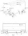
- the FIG. 1 shows a Holzhackschnitzel Transport Car in perspective view.
- the trolley has a respective front and rear wheelset 10, 11 with a above the wheelsets 10, 11 arranged load receptacle 5, 13.
- a center partition wall 2 is arranged, which connect the front and rear load bearing 5, 13.
- On both sides in the longitudinal direction of the center partition wall 2 is ever a cargo container 1.14.
- the cargo container 1.14 consists of an end face 3, 15, perpendicular to the end face 3, 15 in the longitudinal direction of a side wall 4, a side wall opposite the rear wall 4 and a bottom 8. This arrangement of the walls creates an upwardly open, to the Sides and down closed transport container.
- a portion 12 is arranged, which is inclined relative to the vertical of the side wall 4 inwardly.
- the load containers 1, 14 have at the top filling openings 6, 7, which is either open at the top or provided with an open or removable cover. Between the arranged load bearing 5, 13 of the wheelsets 10, 11 are the bottom 8 and pulled down the side wall 4 in section 9, so that the local free space can be used for transport.
- FIG. 2 shows a woodchip trolley in side view.
- the trolley has the front and rear wheelset 10, 11 with the above the wheelsets 10, 11 arranged load receptacle 5, 13.
- the load container 1 rests on the load receptacles 5, 13.
- the side wall 4 in the section 9 deeper drawn to preferably below a hub 16.
- FIG. 3 shows a wood chips transport car in section.
- the two cargo containers 1, 14 are mirror-symmetrical and arranged around the center partition wall 2.
- the bottom 8 of the cargo container 1, 14 is designed at an oblique angle.
- the load container 1, 14 is made deeper towards the wheel axle.
- a floor 17 in this area is also designed at an oblique angle. This angle in the region of the bottom 17 may be steeper than in the region of the bottom 8.
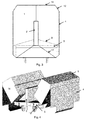
- FIG. 4 shows a woodchip trolley in the discharge.
- Each load container 1, 14 is rotatable outwardly in the lower region of the trolley over the entire length of the trolley on a deflector 34, as in FIG. 6 shown, stored.
- the load containers 1, 14 are pivoted away to the left and right up to a discharge angle on both sides away from the center partition wall 2.
- the side wall 4 opens and unloads the woodchips.
- FIG. 5 and FIG. 6 show an embodiment for an automatic unloading process. Since both cargo containers 1, 14 are constructed mirror-symmetrically, the description of the Figures 5 . 6 limited to one page. The opposite applies accordingly.
- the cargo container 14 is closed.
- the cargo container 14 is open.
- the unloading of the trolley takes place by the lateral unfolding of the two
- the carriage is positioned via an unloading bunker in the region of a stationarily arranged hydraulic fixing device.
- the hydraulic fixing devices is arranged on both sides of the trolley and consists of a Wagenarret Sammlung 29, an opening operation 28, a hydraulic cylinder 31, a power supply 32 and a power connector 33.
- the train For an automatic unloading the train is slowly moved by a locomotive or a cable in the direction of travel.
- photoelectric barriers can be installed for an automatic unloading process, which signals the train driver to the exact position of the trolley. Passing a first photocell activates the automatic discharge process. When passing a first light barrier, the driver receives an acoustic and / or light signal.
- warning devices can be activated in the unloading area. The train driver then has the opportunity to adjust the speed to the process. The car units then passes a second photocell.
- the light barriers are arranged obliquely, so that the gap of the short-coupled car is not recognized.
- a first trolley positioner is hydraulically swiveled onto the track.
- the time interval between the passage of the light barrier 2 and the light barrier 1 is detected. This can be used to determine if the train is moving too fast. In this case, the first carriage positioner is not pivoted. An error message occurs. The train driver must then reset the train and repeat the process.
- Shortly before the car runs onto the first car positioner the rear end of the car passes the first light barrier and a second car positioner is hydraulically swung onto the track.
- the Wagenpositionierer are swung in front of and behind the wheelsets 10, 11, so that the trolley is fixed in position on the track. Both carriage positioners are equipped with damping elements. It is now waited a few seconds until the car is stationary.
- carriage fixators can be hydraulically swiveled in. They protect the car during unloading before a possible tilting and provide it with too electrical drive energy for the spindle drive.
- the hydraulic cylinder 31 moves the Wagenarret ist 29 in the direction of a trolley mounted on the centering pin 35.
- the side wall lock 27 is held in the closed state of the side wall via a retaining spring 26.
- An opening operation for the side wall 4 pushes an opening lever 28 of the side wall lock 27 down.
- the side wall 4 is released.
- a spindle drive 23 is provided at the center partition wall 2. Via a spindle 25, a spindle guide 24 connected to the load container 14 can be driven such that the load container 14 can be pivoted via a deflection 34.
- the power connection 33 is connected to the power supply 32, which supplies the spindle drive 23 with low voltage.
- the spindle drive 23 drives the spindle 25 and thus starts the unloading process.
- the fixedly connected to the container spindle guide 24 now pivots the cargo container 14. Via a cable 22, which is attached to a lever arm 19 of the side wall 4 and a deflection roller 21, the side wall 4 is folded up, see FIG. 6 , The load falls out sideways. As soon as the spindle drive 23 has reached its end position, the process is automatically stopped. After unloading the cargo container 14, the spindle drive is reversed and the side wall 4 closes again. The Wagenarret ist 29 is pivoted back. About the retaining spring 26, the lock 27 of the side wall 14 is pulled up and thus the side wall 14 secured. The unloading process is completed. The train can be moved to unload the next car.
Landscapes
- Engineering & Computer Science (AREA)
- Transportation (AREA)
- Mechanical Engineering (AREA)
- Loading Or Unloading Of Vehicles (AREA)
Applications Claiming Priority (1)
| Application Number | Priority Date | Filing Date | Title |
|---|---|---|---|
| DE102015107000.6A DE102015107000A1 (de) | 2015-05-05 | 2015-05-05 | Holzhackschnitzeltransportwagen |
Publications (1)
| Publication Number | Publication Date |
|---|---|
| EP3090915A1 true EP3090915A1 (fr) | 2016-11-09 |
Family
ID=55967074
Family Applications (1)
| Application Number | Title | Priority Date | Filing Date |
|---|---|---|---|
| EP16168455.0A Withdrawn EP3090915A1 (fr) | 2015-05-05 | 2016-05-04 | Chariot de transport pour copeaux de bois |
Country Status (2)
| Country | Link |
|---|---|
| EP (1) | EP3090915A1 (fr) |
| DE (1) | DE102015107000A1 (fr) |
Citations (8)
| Publication number | Priority date | Publication date | Assignee | Title |
|---|---|---|---|---|
| US366917A (en) * | 1887-07-19 | Dumping-car | ||
| US682206A (en) * | 1900-12-14 | 1901-09-10 | Thomas Lawson | Dumping-car. |
| US704578A (en) * | 1901-03-11 | 1902-07-15 | Edgar M Ray | Dump-car. |
| US769752A (en) * | 1903-06-06 | 1904-09-13 | Lawson Boat And Car Company | Dumping mechanism. |
| US1445215A (en) * | 1920-03-24 | 1923-02-13 | Jr Charles Abercrombie Holt | Dumping body for vehicles |
| US2760815A (en) * | 1954-02-17 | 1956-08-28 | Borde Hillard P La | Vehicle having individual dumpable containers |
| EP1690809A2 (fr) | 2005-02-11 | 2006-08-16 | Innofreight Consulting & Logistics GmbH | Conteneur et dispositif de vidage |
| US20120025590A1 (en) * | 2010-07-29 | 2012-02-02 | Elliott C Scott | Multiple Activated Dumping Roll-Off Container |
Family Cites Families (4)
| Publication number | Priority date | Publication date | Assignee | Title |
|---|---|---|---|---|
| DE366884C (de) * | 1923-01-12 | Hermann Steinkrueger | Kippvorrichtung fuer auf dem Untergestell in zwei Reihen nebeneinander und unabhaengig voneinander angeordneten Ladekasten von Kraftfahrzeugen | |
| US3008433A (en) * | 1958-07-21 | 1961-11-14 | Orenstein & Koppel Ag | Vehicle assemblies |
| DE1239619B (de) * | 1962-09-17 | 1967-04-27 | Feka Fabrik Fuer Spezialfahrze | Muellbehaelter-Transportfahrzeug |
| DE4303349C1 (de) * | 1993-02-05 | 1994-05-19 | Gert Richter | Transportvorrichtung für die Wertstoffentsorgung |
-
2015
- 2015-05-05 DE DE102015107000.6A patent/DE102015107000A1/de not_active Withdrawn
-
2016
- 2016-05-04 EP EP16168455.0A patent/EP3090915A1/fr not_active Withdrawn
Patent Citations (8)
| Publication number | Priority date | Publication date | Assignee | Title |
|---|---|---|---|---|
| US366917A (en) * | 1887-07-19 | Dumping-car | ||
| US682206A (en) * | 1900-12-14 | 1901-09-10 | Thomas Lawson | Dumping-car. |
| US704578A (en) * | 1901-03-11 | 1902-07-15 | Edgar M Ray | Dump-car. |
| US769752A (en) * | 1903-06-06 | 1904-09-13 | Lawson Boat And Car Company | Dumping mechanism. |
| US1445215A (en) * | 1920-03-24 | 1923-02-13 | Jr Charles Abercrombie Holt | Dumping body for vehicles |
| US2760815A (en) * | 1954-02-17 | 1956-08-28 | Borde Hillard P La | Vehicle having individual dumpable containers |
| EP1690809A2 (fr) | 2005-02-11 | 2006-08-16 | Innofreight Consulting & Logistics GmbH | Conteneur et dispositif de vidage |
| US20120025590A1 (en) * | 2010-07-29 | 2012-02-02 | Elliott C Scott | Multiple Activated Dumping Roll-Off Container |
Also Published As
| Publication number | Publication date |
|---|---|
| DE102015107000A1 (de) | 2016-11-10 |
Similar Documents
| Publication | Publication Date | Title |
|---|---|---|
| EP1531135B1 (fr) | Système de transport à rail pour des conteneurs | |
| AT8610U1 (de) | Behälter und entleervorrichtung | |
| DE102008058726B4 (de) | Sicherheitsinspektionssystem für Anhänger | |
| DE19803322A1 (de) | Containerbrücke | |
| DE19510858C2 (de) | Container zum Transport von Gütern | |
| DE671064C (de) | Eisenbahnwagen mit Drehbuehne zum Aufbringen und Abziehen von Strassenfahrzeugen | |
| AT3961U2 (de) | Schüttgutverladewagen | |
| EP0949161A1 (fr) | Procédé et dispositif pour un système de manipulation de fret | |
| EP0490310B1 (fr) | Wagon de chargement pour transporter et stocker de produit en vrac | |
| DE102010014596A1 (de) | Fahrzeug zur Durchführung von Baumaßnahmen im Gleisbereich des Eisenbahnverkehrs | |
| DE102007062324A1 (de) | System für ein Containerverlade-, Güterverlade-, Fahrzeugverlade- und Roll-on roll-off Verfahren in Zügen und anderen transportierenden Einheiten, bei denen es wegen ihrer Länge geboten ist, ein Be- und Entladen von der Seite zu bewerkstelligen, wodurch ein gleichzeitiges und selektives Verladen von Gütern auf jedem Abschnitt der Transporteinheiten ermöglicht wird | |
| DE4123456B4 (de) | Öffnungsfähige Stirnwand für geschlossene doppelstöckige Eisenbahngüterwagen | |
| EP3041992A1 (fr) | Chariot de transbordement de matériau | |
| DE102015107000A1 (de) | Holzhackschnitzeltransportwagen | |
| DE4213925A1 (de) | Wagenzug fuer den schuettgut-transport | |
| DE3720652A1 (de) | Fahrzeugaufbau fuer die hochentleerung von ladegut | |
| DE102009017068B4 (de) | Transportvorrichtung | |
| DE102017109205A1 (de) | Großraum-Behälter II | |
| EP2906753B1 (fr) | Système pour le transport par rail d'objets | |
| DE2038303A1 (de) | Vorrichtung zum Verladen von Kraftwagen in ein Schienenfahrzeug | |
| DE9114708U1 (de) | Schienengängiger Transportwagen | |
| EP3284701B1 (fr) | Récipient de grande capacité | |
| DE285071C (fr) | ||
| AT375048B (de) | Schienengebundener transportwagen fuer schuettgueter | |
| DE472805C (de) | Selbstentlader |
Legal Events
| Date | Code | Title | Description |
|---|---|---|---|
| PUAI | Public reference made under article 153(3) epc to a published international application that has entered the european phase |
Free format text: ORIGINAL CODE: 0009012 |
|
| AK | Designated contracting states |
Kind code of ref document: A1 Designated state(s): AL AT BE BG CH CY CZ DE DK EE ES FI FR GB GR HR HU IE IS IT LI LT LU LV MC MK MT NL NO PL PT RO RS SE SI SK SM TR |
|
| AX | Request for extension of the european patent |
Extension state: BA ME |
|
| STAA | Information on the status of an ep patent application or granted ep patent |
Free format text: STATUS: THE APPLICATION IS DEEMED TO BE WITHDRAWN |
|
| 18D | Application deemed to be withdrawn |
Effective date: 20170510 |