EP3090916A1 - Composant, comprenant un siege et une fixation de siege, destine a etre installe dans un vehicule sur rails, procede de transfert du siege d'une position de rangement dans une position d'utilisation et vehicule sur rail comprenant un tel composant - Google Patents
Composant, comprenant un siege et une fixation de siege, destine a etre installe dans un vehicule sur rails, procede de transfert du siege d'une position de rangement dans une position d'utilisation et vehicule sur rail comprenant un tel composant Download PDFInfo
- Publication number
- EP3090916A1 EP3090916A1 EP16167855.2A EP16167855A EP3090916A1 EP 3090916 A1 EP3090916 A1 EP 3090916A1 EP 16167855 A EP16167855 A EP 16167855A EP 3090916 A1 EP3090916 A1 EP 3090916A1
- Authority
- EP
- European Patent Office
- Prior art keywords
- seat
- assembly
- seat device
- holder
- rail vehicle
- Prior art date
- Legal status (The legal status is an assumption and is not a legal conclusion. Google has not performed a legal analysis and makes no representation as to the accuracy of the status listed.)
- Granted
Links
Images




Classifications
-
- B—PERFORMING OPERATIONS; TRANSPORTING
- B61—RAILWAYS
- B61D—BODY DETAILS OR KINDS OF RAILWAY VEHICLES
- B61D33/00—Seats
- B61D33/0057—Seats characterised by their mounting in vehicles
- B61D33/0078—Seats characterised by their mounting in vehicles adjustably mounted
-
- B—PERFORMING OPERATIONS; TRANSPORTING
- B60—VEHICLES IN GENERAL
- B60N—SEATS SPECIALLY ADAPTED FOR VEHICLES; VEHICLE PASSENGER ACCOMMODATION NOT OTHERWISE PROVIDED FOR
- B60N2/00—Seats specially adapted for vehicles; Arrangement or mounting of seats in vehicles
- B60N2/24—Seats specially adapted for vehicles; Arrangement or mounting of seats in vehicles for particular purposes or particular vehicles
- B60N2/30—Non-dismountable or dismountable seats storable in a non-use position, e.g. foldable spare seats
- B60N2/3002—Non-dismountable or dismountable seats storable in a non-use position, e.g. foldable spare seats back-rest movements
- B60N2/3029—Non-dismountable or dismountable seats storable in a non-use position, e.g. foldable spare seats back-rest movements by composed movement
- B60N2/3031—Non-dismountable or dismountable seats storable in a non-use position, e.g. foldable spare seats back-rest movements by composed movement in a longitudinal-vertical plane
-
- B—PERFORMING OPERATIONS; TRANSPORTING
- B60—VEHICLES IN GENERAL
- B60N—SEATS SPECIALLY ADAPTED FOR VEHICLES; VEHICLE PASSENGER ACCOMMODATION NOT OTHERWISE PROVIDED FOR
- B60N2/00—Seats specially adapted for vehicles; Arrangement or mounting of seats in vehicles
- B60N2/24—Seats specially adapted for vehicles; Arrangement or mounting of seats in vehicles for particular purposes or particular vehicles
- B60N2/30—Non-dismountable or dismountable seats storable in a non-use position, e.g. foldable spare seats
- B60N2/3038—Cushion movements
- B60N2/3063—Cushion movements by composed movement
- B60N2/3065—Cushion movements by composed movement in a longitudinal-vertical plane
-
- B—PERFORMING OPERATIONS; TRANSPORTING
- B60—VEHICLES IN GENERAL
- B60N—SEATS SPECIALLY ADAPTED FOR VEHICLES; VEHICLE PASSENGER ACCOMMODATION NOT OTHERWISE PROVIDED FOR
- B60N2/00—Seats specially adapted for vehicles; Arrangement or mounting of seats in vehicles
- B60N2/24—Seats specially adapted for vehicles; Arrangement or mounting of seats in vehicles for particular purposes or particular vehicles
- B60N2/30—Non-dismountable or dismountable seats storable in a non-use position, e.g. foldable spare seats
- B60N2/3088—Non-dismountable or dismountable seats storable in a non-use position, e.g. foldable spare seats characterised by the mechanical link
- B60N2/3093—Non-dismountable or dismountable seats storable in a non-use position, e.g. foldable spare seats characterised by the mechanical link slides
-
- B—PERFORMING OPERATIONS; TRANSPORTING
- B61—RAILWAYS
- B61C—LOCOMOTIVES; MOTOR RAILCARS
- B61C17/00—Arrangement or disposition of parts; Details or accessories not otherwise provided for; Use of control gear and control systems
- B61C17/04—Arrangement or disposition of driving cabins, footplates or engine rooms; Ventilation thereof
Definitions
- the present invention relates to a seat assembly and a bracket for the seat assembly comprising assembly for placement in a rail vehicle, in particular in a tram vehicle, a method for transferring the seat assembly from a stowed position to a use position and a rail vehicle with the assembly.
- the seat device is preferably arranged in a driver's cab of the vehicle.
- Stowable seats for vehicles are used to respond flexibly to changing conditions. For example, it may be necessary to provide the space occupied by the seats for certain objects, such as a wheelchair or luggage.
- This is in US 2004/0113451 A1 a stowable seat assembly indicated for vehicles having a seat formed from the seat and backrest, which are pivotally connected to each other, formed seat, wherein the seat between a use position and two different parking positions is movable.
- the seat can either be moved in the vehicle direction or pivoted by 90 ° relative to the vehicle direction.
- Out CN 201530335 U is a folding seat with a seat and a backrest, which are pivotable against each other shown.
- JP 2006-137265 A is given a folding seat for a vehicle whose seat is pivotable against the backrest.
- the folded seat is housed in a niche of a vehicle wall.
- a similar arrangement is also in GB 2 140 283 A described.
- DE 10 2008 047 659 A1 indicates a foldable seat in a driver's cab, in particular in a rail-bound vehicle.
- the seat comprises a holding frame and a seat supported by the holding frame and pivotable from a use position to an easy exit position and vice versa, and a pivotable backrest.
- the seat surface and the backrest are each arranged in the easy exit position substantially parallel to a plane which extends substantially perpendicular to the respective planes in which the seat surface and the backrest are in the position of use.
- Such a seat can be used in particular as a driving instructor seat in the driver's cab.
- a rail vehicle is specified with a driver's cab, which has a folding seat device.
- This seat assembly is inserted into a Geschränk in which it is then in the folded state.
- the seat device has a seat and a pivoting backrest.
- For retracting the sitting in the folded state seat device in the Geschränk in and out of this telescopic rails are provided.
- the present invention seeks to find an arrangement for a seat device in a rail vehicle, in particular a tram, in which the seat device in the use position allows a comfortable sitting position and claimed in the stowed only small space, so that the reliability of Vehicle is not affected. Furthermore, it is very important that the seat assembly from the use position in the stowed position is quickly convertible to allow in an emergency that the rail vehicle, in particular its driver's station, can be evacuated quickly. Because the device takes in the position of use considerable space in the driver's cab and hinders the exit. In addition, the seat assembly should also ensure that it is simple in construction to ensure that it is not prone to damage and contamination and is also easy to repair.
- 'seat device', 'extension device', '(longitudinal) guide', 'support frame', 'guide element', etc. so may also be understood in each case the corresponding plural forms, namely 'Seats', 'Pull-out devices', '(Longitudinal) guides', 'Supporting frames', 'Guiding elements', etc., and vice versa, unless expressly stated otherwise.
- a structural unit comprising, preferably formed by, a seat device and a mount for the seat device, for arrangement in a rail vehicle.
- these objects are achieved with a method for transferring the seat assembly from a stowage position to a use position.
- the holder of the assembly according to the invention is held by a support member in the rail vehicle.
- the seat device can be transferred from a use position to a stowed position and vice versa.
- the seat device and the at least one holder are connected to each other via corresponding guide means, so that the seat device is movable relative to the at least one holder.
- the corresponding guide means are formed by at least one extension device and at least one corresponding to the at least one extension device guide element (guide element).
- the at least one extension device is articulated via the at least one holder on the support element pivotable.
- the seat assembly is in the stowed position in a substantially vertical position, i. preferably up to ⁇ 30 ° to the vertical, particularly preferably exactly vertical, arranged.
- the rail vehicle is preferably a tram, but may also be another rail-bound vehicle, such as a railcar, a locomotive or other passenger transport vehicle, in particular passenger transport traction vehicle, in local and long-distance transport.
- the present invention can be used in any rail vehicle in which a seat device, in particular in a driver's station, is to be arranged.
- the seat device according to the present invention is to be installed in a driver's cab, there is the possibility that the rail vehicle has a driver's station exclusively at one end, or the rail vehicle can each have a driver's stand at both ends.
- a seat device according to the present invention may be installed in each of the two driver stands or only in one of the two driver stands.
- the seating device according to the invention ensures that it is always available in the rail vehicle, in particular in the driver's cab, and does not have to be procured from another location inside or outside the vehicle if necessary. Because the seat device is permanently installed in the rail vehicle on site.
- the ease of use when setting up or stowing the seat assembly allows their quick availability and also a quick transfer to the stowage position. This is achieved by a simple mechanism provided for this purpose so that the device is always ready for use. This ensures inter alia that the rail vehicle, in particular the driver's station in the rail vehicle, can be evacuated quickly in an emergency.
- the seat device By mounting the seat device on the pivotally supported extension devices a space-saving structure is created, with which the available space is optimally used, especially in the stowed position of the seat assembly.
- the seat device By namely the seat device is arranged in the stowed position in a vertical position, only a small space is required for their placement in the rail vehicle.
- the interior space in the vehicle can be made sufficiently large even if the width of the vehicle is low. Because of the invention, the available interior can be maximized even with a small width of the vehicle. This is achieved by the fact that the seat concept is characterized by a narrow design, so that the space required in the stowed state is minimized.
- the seat device For the person who uses the seat device is with the seat device according to the invention, a satisfactory seating comfort available, since the small design also ensures accommodation of upholstered seats. If the seat assembly is installed in the driver's cab, it can be used as a driving instructor seat. Alternatively, it can also be used as an emergency seat, for example for passengers, to be used. The simple structure of the seat assembly is not prone to damage and contamination and can be easily repaired if necessary.
- the seat device can be accommodated, for example, in a wardrobe in the rail vehicle, in particular in a wardrobe in the driver's cab in the rail vehicle.
- the seat device can be attached via the extension devices to a component of the cabinet, for example on an inner wall, side wall or front wall of the cabinet.
- the seat device can also be fastened to the inner wall of the rail vehicle, in particular to a wall element of the inner or side wall, or to support struts in the wall region of the rail vehicle.
- the space provided for this part of the cabinet or the inner, side or front wall of the rail vehicle is the support element that holds the seat assembly on the extension devices.
- the holder may be designed in the form of a flap drawer.
- the drawer devices may be formed by guide grooves or guide rails attached to inner or side walls of the cabinet or struts supporting the inner wall panels of the rail vehicle or to the flap drawer.
- the extension devices may be located on the seat assembly. In this case, corresponding to the respective extension device guide elements (guide elements) are attached to the support element.
- the seating device in the stowed position is preferably arranged completely in a cavity formed by walls for the interior of the rail vehicle, which is closed to the outside by the vehicle outer skin, for example within a cubicle, in particular in the driver's compartment of the rail vehicle. or, for example, within a cavity, which is separated by inner wall elements from the interior of the rail vehicle, such as a passenger or driver's compartment.
- the seat device is not completely in the stowed position within this cavity but only partially and with the remaining part in the interior of the rail vehicle, such as the driver's compartment, protrudes.
- the seat device is held on two opposite longitudinal sides on the at least one extension device. This allows a stable mounting of the seat device to the support element, since the seat device is held in this case via two extension devices. In principle, it is of course also possible to keep the seat assembly only on one side. This then requires a very solid and robust mount on this side.
- the at least one pull-out device is held pivotably by the support element via the at least one holder so that the seat device can first be pivoted into an operating position with the pull-out device for transferring from the stowage position into the use position toward the operator from which the seat device can be transferred to the position of use.
- the seat device In the operating position, the seat device is inclined relative to the stowage position by a pivot angle ⁇ against the vertical or the stowed position (see below). The pivoting relative to the vertical or relative to the stowage position in the operating position facilitates the operation, because the seat assembly can then simply be pulled upwards from this position and then transferred to the position of use.
- the seat device Before pivoting into the operating position, the walls delimiting the cavity hinder the extension of the seat device into the position of use.
- the seat device is located in a preferred embodiment in the stowed position completely in the cavity and is partially pivoted out by the pivoting of the extension devices in the operating position from the cavity.
- the pull-out devices can preferably be articulated to the support element in its lower area (relative to the arrangement of the seat device in the stowage position).
- the guide elements can preferably in a corresponding to the lower region (relative to the arrangement of the seat device in the stowed position) of the pullout device area be attached to the support element.
- the assembly according to the invention further preferably has a support frame on the side facing the interior of the rail vehicle.
- This support frame serves to support and support the seat assembly in the position of use, so that it is arranged in the position of use in a horizontal position and a person can sit on it.
- the support frame takes on the weight of the seat assembly and sitting on this person.
- the seat device may be equipped instead of a support frame with an auxiliary leg, which can be hinged to the underside of the seat and swung to support the seat device on the bottom surface of the interior of the rail vehicle.
- auxiliary leg which can be hinged to the underside of the seat and swung to support the seat device on the bottom surface of the interior of the rail vehicle.
- the at least one pull-out device is attached to a flap drawer, which is held pivotably by the support element.
- the flap drawer has at least side walls and the outer wall element.
- the at least one holder for the seat device is formed by the flap drawer having the at least one pull-out device.
- the flap drawer is pivotally supported by the support member.
- the seat device is movable relative to and along the extension devices.
- the flap drawer in yet another preferred embodiment of the present invention each having a pull-out device with a guide, preferably with a longitudinal guide, on opposite inner sides, preferably on these side walls have. Because the side walls of the flap drawer are preferably opposite each other, so that the guides can guide and hold the seating device arranged therebetween.
- These guides may be formed by simple guide grooves in the side walls or by guide rails attached to the insides of the side walls.
- the corresponding to the extension devices guide elements are arranged in this case on the seat device.
- guide elements which correspond to extension devices can also be arranged on the side walls of the flap drawer and the drawer devices can be arranged on the seat device.
- the outer wall member of the flap drawer may form part of the outer wall of, for example, a cabinet or the inner wall of the rail vehicle when the seat assembly is in the stowed position.
- This outer wall element can preferably be flush with the rest of the outer wall of the cabinet or the inner wall to the interior of the rail vehicle, so that, apart from any existing joints between this outer wall element and the rest of the wall, together with the remaining wall, a continuous wall surface is formed.
- the side walls and the outer wall element preferably form a box-like structure, namely the flap drawer.
- the side walls may preferably be connected at a right angle to the outer wall element.
- the at least one holder is formed by a respective attachment of the at least one extension device to the support member, and the at least one extension device by at least one (longitudinal) guide, in particular in the form of a guide rail , educated.
- the assembly according to the present invention no flap loading, but only the extension devices, namely guide (s), preferably longitudinal guides, and in particular guide rails.
- the at least one extension device is therefore not fastened to the box-like wall elements of the flap drawer.
- the holder further preferably has a support frame in this embodiment, which is provided instead of the outer wall element of the first embodiment variant.
- the flap drawer in this embodiment variant can also be replaced by guide elements corresponding to the drawer devices on the seat device.
- a support frame is preferably provided in this second embodiment that is located on the side facing the interior of the rail vehicle (longitudinal) - guides.
- the support frame may be formed by a scaffold made of metal or plastic, which is formed for example of bands or tubes or rods or profile strands.
- a bracket with a horizontal support surface. It is preferably pivotable together with the guides on the support element held and is pivoted together with these from the stowed in the operating position and vice versa.
- the (longitudinal) guide of the pull-out device in each of the embodiments and forms described above is preferably formed by an elongated Konkavprofilelement, more preferably at least one guide element, for example on the seat device, translationally movable therein , particularly preferably form-fitting, holds.
- the (longitudinal) guide can be in the form of a profile rail, for example made of metal or plastic.
- the at least one guide element, for example on the seat device is preferably formed by a rotatable element which, for example, rolls on a running surface of the (longitudinal) guide, preferably on a running surface on the inner surface of the concave profile.
- the at least one guide element can also be designed in the form of a (non-rolling) sliding element.
- a pull-out device may be formed in the form of at least one groove in the side walls of the flap drawer or in wall-like elements.
- the extension devices are preferably equipped with upper stop devices so that the seat device can not escape from the guide during retraction, i. that, for example, the guide elements always run within the concave profile and this can not leave.
- the (longitudinal) guides can be closed at the ends by a barrier, in particular at the pivot point of the extension device on the support element opposite end.
- the extension devices are formed by (longitudinal) guides, if, in addition, a support frame is present, on which rest the seat assembly in the position of use and can support.
- the support frame limited as the flap drawer in the case of the first embodiment, the pivoting of the seat assembly from a position parallel to the (longitudinal) guides the guide rails.
- the at least one pull-out device or the flap drawer can be pivotable by a maximum pivot angle ⁇ relative to the support element.
- angle limiting devices can be provided which prevent the extension device or the flap drawer from being pivoted beyond the maximum pivot angle ⁇ out of the stowed position.
- the angle limiting devices can be realized by a flexible connecting element, such as a chain, which is fastened with its ends to the supporting element and a pull-out device or the flap drawer.
- the angle limiting devices may also be formed by stop blocks, which are located on the support member, ie there attached or integral part of this element, and against which the pull-out devices or the flap drawer strike during pivoting.
- the maximum pivot angle ⁇ may preferably be in a range of 5 ° to 85 °, more preferably in a range of 10 ° to 45 °, more preferably in a range of 15 ° to 30 °, and most preferably at about 20 °, relative to the stowage position of the pullout device or flap drawer.
- the seat device is formed by a seat surface and a backrest, which are articulated to each other (folding seat), so that the seat surface and the backrest in the stowed position can be arranged adjacent to each other.
- the sides of the seat surface and the back rest are preferably adjacent to one another, which come into contact with the user in the position of use, for example, there existing upholstery elements.
- the seat and the backrest are preferably each formed by a frame and a pad attached thereto.
- the pads come into contact with each other.
- the seat and the backrest of the seat device are preferably hinged to each other via a hinge.
- the seat device has only a seat, but not a backrest.
- the seat is in the position of use in a horizontal position on the at least one maximum against the support member pivoted support frame, so that a person can take a seat on the seat comfortably.
- levels of the upper stop devices on the extension devices and the upper edge of the support frame or the outer wall element of the flap drawer are to be aligned with each other in a suitable manner.
- the seat device can be arranged on the support element in such a way that the pivot axis about which the extension devices are pivotable relative to the support element extends parallel to the axis about which the seat surface and the backrest are pivotable relative to one another.
- the backrest can be raised towards the inner wall of the rail vehicle in order to convert the seat device into the position of use.
- the person sitting on it can in this case look into the interior of the vehicle.
- the seat device forms an emergency seat, which can be used not only in the driver's cab of the rail vehicle but in the entire rail vehicle, for example, for passengers.
- the seat device or a flap drawer holding the seat device can be locked against pivoting, so that the seat device can not be unintentionally swung out of the cavity.
- the lock can also be designed to prevent unauthorized use (obstruction).
- For locking serve conventional devices, such as snaps, hooks, magnetic locks, Vorlienen with locking devices and the like.
- the seat device Since the holder for the seat device, for example, in the lower region in the cabinet preferably via joints, which allow pivoting about a horizontal axis is stored, the seat device can be swung out with the flap drawer by a pivot angle ⁇ of, for example 20 ° from the vertical forward. As a result, the arranged in the flap load seat assembly is visible. In this position, the seat assembly is in the operating position.
- the seat assembly - initially in the configuration with adjoining seat and backrest - guided by the (longitudinal) guides out of the flap drawer are pulled upwards.
- This translational operation ends at upper stops on the (longitudinal) guides / guide rails.
- the package of seat and backrest is tilted in the horizontal / pivoted until it rests on the outer wall element of the flap drawer. In this position, the package is oriented horizontally. If the seat assembly has a backrest, it can then be raised, i. either preferably opposite to the direction of travel or to the inner wall of the rail vehicle. In this position, the seat assembly is finally in the position of use.
- the seat device is held, for example, by two separate guide rails with (longitudinal) guides and a support frame or without support frame or if the (longitudinal) guides both aforementioned embodiments not articulated on the support element but on the seat device or integrally formed in the seat assembly. If no support frame is present, an auxiliary leg is extended during pivoting of the seat assembly in the horizontal position, which is then supported on the bottom surface of the interior of the rail vehicle.
- like reference numerals designate like elements and / or elements having the same function.
- the figures do not always show the objects to each other in scale. Furthermore, the size ratios of individual elements to those of others in a figure or between the figures are not in each case to scale shown to each other.
- the assembly 100 according to the invention comprising seat device 200 and holder 300 in a rail vehicle 1 is particularly suitable for use in a driver's station 10 of the rail vehicle.
- a driver's station in a tram vehicle is in Fig. 1 shown.
- the seat device is formed in the present case by a seat 210 and a backrest 220, which are articulated to each other.
- the seat device can alternatively also be formed exclusively by a seat surface.
- the seat device is shown in the configuration of the first arrangement variant with a backrest aligned counter to the direction of travel.
- the assembly 100 is housed in a lateral Geschränk 20 in the present case ( Fig. 1 . 2 ).
- the cabinet forms a support element for the unit.
- the support member may also be a wall element that limits the interior of the rail vehicle to the outside. Therefore, the structural unit according to the invention can also be installed elsewhere in the rail vehicle than in the driver's seat 10, for example in a passenger compartment.
- the assembly 100 according to the invention is formed in a first embodiment by a seat device 200 and a holder 300 in the form of a flap shutter 310.
- This unit is in Fig. 2 reproduced in the stowed position, wherein the seat assembly is not shown for ease of illustration (see Fig. 3 to 5 ).
- the unit is housed in a side cabinet 20.
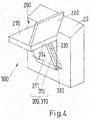
- the flap drawer forms a hinged compartment which can be pivoted forwardly about a hinge 320 located in the lower region of the flap drawer ( Fig. 3 ). This joint is located laterally in the walls of the cabinet (attachment not shown).
- the flap drawer is formed by a (front) outer wall member 311 and by two side walls 312.
- Fig. 6 the assembly 100 is shown with the seat assembly 200 and the holder 300 in the form of the flap tray 310 in a side schematic sectional view, wherein the assembly is installed in the cabinet 20.
- the flap shutter 310 is again formed by an outer wall element 311 and two side walls 312. In each of the two side walls there is a hinge 320 in order to be able to swing the flap drawer out of the cupboard by a pivoting angle ⁇ (cf. Fig. 3 . 7 ).
- the seat device 200 formed by the seat surface 210 and the backrest 220 is fixed.
- the seat and the backrest are hinged to each other via a seat hinge 230, which allows pivoting about a horizontal axis.
- a seat hinge 230 which allows pivoting about a horizontal axis.
- stowage of the assembly 100 are the seat and the backrest to each other.
- the seat is formed by a seat base 211 and a seat cushion 212
- the seat back is constituted by a seatback base body 221 and a seatback cushion 222.
- the two upholstery parts 212, 222 are in the stowed position, as in Fig. 6 shown, against each other.
- the embodiment shown in this figure shows the emergency seat of Fig.
- the seat device 200 is fastened to the flap load 310 by means of guide rails 330 (pull-out devices). On the inside of each of the two side walls 312 of the flap drawer one of these guide rails is arranged.
- the guide rails are opposite each other, so that the seat device with guide elements 231 (corresponding to the extension devices guide elements), such as pins, is guided in the guide rails.
- Fig. 9 is a section AA in the plane of the rotation axis of the seat joint 230 of the seat assembly according to Fig. 6 shown.
- the guide rails form longitudinal guides 331 in the form of slots.
- the slots are located in the guide rails formed by Konkavprofilschienen ( Fig. 6 ).
- the guide elements on the seat device 200, in particular on the seat base body 211 are formed by guide blocks, which are held in the guide rails in a form-fitting manner in the elongate longitudinal guides 331.
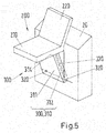
- the seat assembly For transferring the seat device 200 from the stowage position ( Fig. 2 . 6 ) first into an operating position ( Fig. 3 ), then in an upper position with the seat assembly pulled out ( Fig. 7 ) and then into the position of use ( Fig. 5 . 8th ), the seat assembly can be converted for use.
- the seat device 200 Only when the seat device 200 has reached the upper stop 333 of the guide rails 330, it can be pivoted about the hinge axis of the seat joint 230 and the pin 231. In this case, it is conveyed into the horizontal position so that the seat surface rests with its seat base body 211 on the upper edge 314 of the outer wall element 311 (supporting frame) of the flap shutter 310 (FIG. Fig. 5 . 8th ).
- FIG. 10 is, as shown for the second arrangement variant, a sectional view of the assembly 100 with seat 200 and holder 300 (flap load 310) in a cabinet 20 in the upper position also shown for this first arrangement variant. In this case, does not serve the hinge axis of the seat hinge 230 (not shown) for guiding the seat assembly in the guide rails 330 (extension devices).
- the guide elements 231 are attached to fasteners 234 on the seat base body 211 of the seat 210, which project laterally so that they can engage in the longitudinal guides 331 of the guide rails.
- bracket 300 is not formed by a shutter load 310 but by attachment of separate guide rails 330 and a support frame 311 to the support member 20 (not shown in the figures).
- the guide rails are then held without side walls 312 of the flap drawer in the lower joints 320 in the cabinet 20 or other support member and are pivotable about the hinge axis formed by these.
- the support frame replaces the outer wall element 311 of the flap drawer and closes off the space in the cupboard in which the seat device 200 is located.
- the seat device can rest in this case on an upper edge of this frame when it is in the position of use.
Landscapes
- Engineering & Computer Science (AREA)
- Mechanical Engineering (AREA)
- Transportation (AREA)
- Aviation & Aerospace Engineering (AREA)
- Automation & Control Theory (AREA)
- Seats For Vehicles (AREA)
Priority Applications (1)
| Application Number | Priority Date | Filing Date | Title |
|---|---|---|---|
| PL16167855T PL3090916T3 (pl) | 2015-05-06 | 2016-05-02 | Jednostka konstrukcyjna, obejmująca urządzenie do siedzenia i element mocujący, przeznaczone do umieszczenia w pojeździe szynowym, sposób sprowadzania urządzenia do siedzenia z pozycji złożenia do pozycji użytkowej oraz pojazd szynowy z co najmniej jedną jednostką konstrukcyjną |
Applications Claiming Priority (1)
| Application Number | Priority Date | Filing Date | Title |
|---|---|---|---|
| DE102015208351.9A DE102015208351B4 (de) | 2015-05-06 | 2015-05-06 | Baueinheit, umfassend eine Sitzeinrichtung und eine Halterung für die Sitzeinrichtung, zur Anordnung in einem Schienenfahrzeug, Verfahren zum Überführen der Sitzeinrichtung von einer Verstaustellung in eine Gebrauchsstellung sowie Schienenfahrzeug mit mindestens einer Baueinheit |
Publications (2)
| Publication Number | Publication Date |
|---|---|
| EP3090916A1 true EP3090916A1 (fr) | 2016-11-09 |
| EP3090916B1 EP3090916B1 (fr) | 2020-03-18 |
Family
ID=55968908
Family Applications (1)
| Application Number | Title | Priority Date | Filing Date |
|---|---|---|---|
| EP16167855.2A Active EP3090916B1 (fr) | 2015-05-06 | 2016-05-02 | Composant, comprenant un siege et une fixation de siege, destine a etre installe dans un vehicule sur rails, procede de transfert du siege d'une position de rangement dans une position d'utilisation et vehicule sur rail comprenant un tel composant |
Country Status (4)
| Country | Link |
|---|---|
| EP (1) | EP3090916B1 (fr) |
| DE (1) | DE102015208351B4 (fr) |
| ES (1) | ES2796306T3 (fr) |
| PL (1) | PL3090916T3 (fr) |
Cited By (2)
| Publication number | Priority date | Publication date | Assignee | Title |
|---|---|---|---|---|
| FR3070949A1 (fr) * | 2017-09-12 | 2019-03-15 | Alstom Transport Technologies | Dispositif auxiliaire de conduite pour un vehicule ferroviaire automatique, presentant un encombrement reduit |
| FR3070951A1 (fr) * | 2017-09-12 | 2019-03-15 | Alstom Transport Technologies | Dispositif auxiliaire de conduite pour un vehicule ferroviaire automatique, avec appui pour un conducteur |
Families Citing this family (5)
| Publication number | Priority date | Publication date | Assignee | Title |
|---|---|---|---|---|
| US12077068B2 (en) | 2020-11-09 | 2024-09-03 | Ford Global Technologies, Llc | Authorization-based adjustment of passenger compartment arrangement |
| US11904732B2 (en) | 2020-11-09 | 2024-02-20 | Ford Global Technologies, Llc | Vehicular system capable of adjusting a passenger compartment from a first arrangement to a child care arrangement |
| US11772517B2 (en) | 2020-11-09 | 2023-10-03 | Ford Global Technologies, Llc | Vehicular system capable of adjusting a passenger compartment from a child seat arrangement to a second arrangement |
| US12257932B2 (en) | 2020-11-09 | 2025-03-25 | Ford Global Technologies, Llc | Exterior imager utilized in adjusting a passenger compartment arrangement |
| EP4474212B1 (fr) | 2023-06-08 | 2026-03-18 | ALSTOM Holdings | Unité de structure pour un véhicule terrestre, à siège rabattable |
Citations (12)
| Publication number | Priority date | Publication date | Assignee | Title |
|---|---|---|---|---|
| DE309572C (fr) * | ||||
| US187817A (en) * | 1877-02-27 | Improvement in folding seats | ||
| US464046A (en) * | 1891-12-01 | Stool | ||
| GB2140283A (en) | 1983-05-23 | 1984-11-28 | Ikeda Bussan Co | Auxiliary seat assembly for use in vehicles |
| FR2668909A1 (fr) | 1990-11-08 | 1992-05-15 | Husson Collectivites Sa | Gradin modulaire pourvu de sieges escamotables. |
| DE10217794A1 (de) | 2002-04-20 | 2003-11-06 | Aguti Prod Entw & Design Gmbh | Fahrzeugsitz, insbesondere als Notsitz in Krankenwagen |
| DE10241250A1 (de) * | 2002-09-06 | 2004-04-01 | Bombardier Transportation Gmbh | Sitzeinrichtung |
| US20040113451A1 (en) | 2002-12-06 | 2004-06-17 | Maciej Szymanski | Stowable seat assembly |
| JP2006137265A (ja) | 2004-11-11 | 2006-06-01 | Toyota Auto Body Co Ltd | 車両用シート格納装置 |
| DE102008047659A1 (de) | 2008-09-12 | 2010-03-25 | Bombardier Transportation Gmbh | Fahrlehrersitz |
| CN201530335U (zh) | 2009-05-19 | 2010-07-21 | 上海华普汽车有限公司 | 折叠座椅 |
| DE102009034681A1 (de) | 2009-07-24 | 2011-02-03 | Bombardier Transportation Gmbh | Schienenfahrzeug mit einer klappbaren Sitzeinrichtung |
Family Cites Families (6)
| Publication number | Priority date | Publication date | Assignee | Title |
|---|---|---|---|---|
| DE90947C (fr) * | ||||
| GB117636A (en) * | 1917-07-02 | 1919-03-27 | Charles Adolphe Arbenz | Improvements in or relating to Seats. |
| US1355005A (en) * | 1919-04-23 | 1920-10-05 | American Car Company | Car-seat |
| DE380799C (de) * | 1921-09-28 | 1923-09-10 | Konrad Gebhard Wagen & Karosse | Zusammenklappbarer Notsitz, insbesondere fuer Kraftwagen |
| US1534837A (en) * | 1924-04-26 | 1925-04-21 | J G Brill Co | Car seat |
| DD10926A1 (de) * | 1953-12-10 | 1955-12-06 | Reinhold Finger | Fahrerklappsitz, insbesondere für strassenbahntriebwagen |
-
2015
- 2015-05-06 DE DE102015208351.9A patent/DE102015208351B4/de not_active Expired - Fee Related
-
2016
- 2016-05-02 EP EP16167855.2A patent/EP3090916B1/fr active Active
- 2016-05-02 ES ES16167855T patent/ES2796306T3/es active Active
- 2016-05-02 PL PL16167855T patent/PL3090916T3/pl unknown
Patent Citations (12)
| Publication number | Priority date | Publication date | Assignee | Title |
|---|---|---|---|---|
| DE309572C (fr) * | ||||
| US187817A (en) * | 1877-02-27 | Improvement in folding seats | ||
| US464046A (en) * | 1891-12-01 | Stool | ||
| GB2140283A (en) | 1983-05-23 | 1984-11-28 | Ikeda Bussan Co | Auxiliary seat assembly for use in vehicles |
| FR2668909A1 (fr) | 1990-11-08 | 1992-05-15 | Husson Collectivites Sa | Gradin modulaire pourvu de sieges escamotables. |
| DE10217794A1 (de) | 2002-04-20 | 2003-11-06 | Aguti Prod Entw & Design Gmbh | Fahrzeugsitz, insbesondere als Notsitz in Krankenwagen |
| DE10241250A1 (de) * | 2002-09-06 | 2004-04-01 | Bombardier Transportation Gmbh | Sitzeinrichtung |
| US20040113451A1 (en) | 2002-12-06 | 2004-06-17 | Maciej Szymanski | Stowable seat assembly |
| JP2006137265A (ja) | 2004-11-11 | 2006-06-01 | Toyota Auto Body Co Ltd | 車両用シート格納装置 |
| DE102008047659A1 (de) | 2008-09-12 | 2010-03-25 | Bombardier Transportation Gmbh | Fahrlehrersitz |
| CN201530335U (zh) | 2009-05-19 | 2010-07-21 | 上海华普汽车有限公司 | 折叠座椅 |
| DE102009034681A1 (de) | 2009-07-24 | 2011-02-03 | Bombardier Transportation Gmbh | Schienenfahrzeug mit einer klappbaren Sitzeinrichtung |
Cited By (2)
| Publication number | Priority date | Publication date | Assignee | Title |
|---|---|---|---|---|
| FR3070949A1 (fr) * | 2017-09-12 | 2019-03-15 | Alstom Transport Technologies | Dispositif auxiliaire de conduite pour un vehicule ferroviaire automatique, presentant un encombrement reduit |
| FR3070951A1 (fr) * | 2017-09-12 | 2019-03-15 | Alstom Transport Technologies | Dispositif auxiliaire de conduite pour un vehicule ferroviaire automatique, avec appui pour un conducteur |
Also Published As
| Publication number | Publication date |
|---|---|
| DE102015208351A1 (de) | 2016-11-10 |
| ES2796306T3 (es) | 2020-11-26 |
| EP3090916B1 (fr) | 2020-03-18 |
| PL3090916T3 (pl) | 2020-10-19 |
| DE102015208351B4 (de) | 2017-01-05 |
Similar Documents
| Publication | Publication Date | Title |
|---|---|---|
| DE102015208351B4 (de) | Baueinheit, umfassend eine Sitzeinrichtung und eine Halterung für die Sitzeinrichtung, zur Anordnung in einem Schienenfahrzeug, Verfahren zum Überführen der Sitzeinrichtung von einer Verstaustellung in eine Gebrauchsstellung sowie Schienenfahrzeug mit mindestens einer Baueinheit | |
| EP2217467B1 (fr) | Siège de véhicule automobile | |
| EP2456650B1 (fr) | Tramway doté d'un siège rabattable supplémentaire pour la cabine de conduite | |
| DE60214510T2 (de) | Schwenksitz für Heckklappe | |
| DE19906648B4 (de) | Vorrichtung zur Führung eines Ladebodens in einem Gepäckraum eines Personenkraftfahrzeugs | |
| DE102016109789B4 (de) | Sitzsystem für eine Kabine eines Transportmittels mit kompaktierbarer Sitzreihe | |
| DE10310792A1 (de) | Fahrzeugsitzbaueinheit | |
| EP0689954A2 (fr) | Aménagement de siège, notamment pour le compartiment de chargement ou de passenger d'un véhicule automobile | |
| DE102018220638A1 (de) | Vorrichtung für ein Fahrzeug und ein Fahrzeug | |
| DE102007063565A1 (de) | Kraftfahrzeugsitz | |
| EP1663698B1 (fr) | Siege de vehicule a position de chargement | |
| DE102010046562B4 (de) | Sitz oder Sitzanlage für ein Kraftfahrzeug und insbesondere einen Lieferwagen | |
| EP1777100B1 (fr) | Système de dossier | |
| DE102007052529A1 (de) | Ein Sitz und Sitzanordnung in einem Kraftfahrzeug | |
| DE102007045838A1 (de) | Fahrzeugsitz mit einer für den Benutzungsfall aufbaubaren Tischstruktur | |
| EP1615795B1 (fr) | Dispositif de guidage longitudinal pour un siege de vehicule automobile | |
| EP3727265A1 (fr) | Siège pour véhicule d'intérêt général et spécial | |
| DE4112270C1 (en) | Releasable ambulance stretcher support platform - has its middle section secured to horizontal, transverse swivel axis with ends fitted to holder on vehicle | |
| EP1637441B1 (fr) | Couchette réglable | |
| DE102004001431A1 (de) | Klappbare Liege für eine Fahrgastzelle eines Kraftfahrzeugs | |
| DE102007023371B4 (de) | Fahrzeugsitz mit verschiebbaren Querstreben und Kraftfahrzeug mit einem solchen Fahrzeugsitz | |
| DE102019135314B4 (de) | Schienenfahrzeugwagen mit anpassbarer Abteilaufteilung | |
| DE102019128938A1 (de) | Vorichtung zur Höhenanpassung für einen Fahrzeugladeraum | |
| DE102005017772A1 (de) | Kraftfahrzeug mit einem um 180° schwenkbaren Sitz | |
| DE10152669B4 (de) | Vorrichtung zum Verschieben eines Fahrzeugsitzes |
Legal Events
| Date | Code | Title | Description |
|---|---|---|---|
| PUAI | Public reference made under article 153(3) epc to a published international application that has entered the european phase |
Free format text: ORIGINAL CODE: 0009012 |
|
| AK | Designated contracting states |
Kind code of ref document: A1 Designated state(s): AL AT BE BG CH CY CZ DE DK EE ES FI FR GB GR HR HU IE IS IT LI LT LU LV MC MK MT NL NO PL PT RO RS SE SI SK SM TR |
|
| AX | Request for extension of the european patent |
Extension state: BA ME |
|
| STAA | Information on the status of an ep patent application or granted ep patent |
Free format text: STATUS: REQUEST FOR EXAMINATION WAS MADE |
|
| 17P | Request for examination filed |
Effective date: 20170418 |
|
| RBV | Designated contracting states (corrected) |
Designated state(s): AL AT BE BG CH CY CZ DE DK EE ES FI FR GB GR HR HU IE IS IT LI LT LU LV MC MK MT NL NO PL PT RO RS SE SI SK SM TR |
|
| RIC1 | Information provided on ipc code assigned before grant |
Ipc: B61D 33/00 20060101AFI20190806BHEP |
|
| GRAP | Despatch of communication of intention to grant a patent |
Free format text: ORIGINAL CODE: EPIDOSNIGR1 |
|
| STAA | Information on the status of an ep patent application or granted ep patent |
Free format text: STATUS: GRANT OF PATENT IS INTENDED |
|
| INTG | Intention to grant announced |
Effective date: 20191001 |
|
| GRAS | Grant fee paid |
Free format text: ORIGINAL CODE: EPIDOSNIGR3 |
|
| GRAA | (expected) grant |
Free format text: ORIGINAL CODE: 0009210 |
|
| STAA | Information on the status of an ep patent application or granted ep patent |
Free format text: STATUS: THE PATENT HAS BEEN GRANTED |
|
| AK | Designated contracting states |
Kind code of ref document: B1 Designated state(s): AL AT BE BG CH CY CZ DE DK EE ES FI FR GB GR HR HU IE IS IT LI LT LU LV MC MK MT NL NO PL PT RO RS SE SI SK SM TR |
|
| REG | Reference to a national code |
Ref country code: GB Ref legal event code: FG4D Free format text: NOT ENGLISH |
|
| REG | Reference to a national code |
Ref country code: DE Ref legal event code: R096 Ref document number: 502016009168 Country of ref document: DE |
|
| REG | Reference to a national code |
Ref country code: AT Ref legal event code: REF Ref document number: 1245576 Country of ref document: AT Kind code of ref document: T Effective date: 20200415 Ref country code: IE Ref legal event code: FG4D Free format text: LANGUAGE OF EP DOCUMENT: GERMAN |
|
| REG | Reference to a national code |
Ref country code: CH Ref legal event code: NV Representative=s name: PATENTANWALT DIPL.-ING. (UNI.) WOLFGANG HEISEL, CH |
|
| RAP2 | Party data changed (patent owner data changed or rights of a patent transferred) |
Owner name: BOMBARDIER TRANSPORTATION GMBH |
|
| PG25 | Lapsed in a contracting state [announced via postgrant information from national office to epo] |
Ref country code: NO Free format text: LAPSE BECAUSE OF FAILURE TO SUBMIT A TRANSLATION OF THE DESCRIPTION OR TO PAY THE FEE WITHIN THE PRESCRIBED TIME-LIMIT Effective date: 20200618 Ref country code: RS Free format text: LAPSE BECAUSE OF FAILURE TO SUBMIT A TRANSLATION OF THE DESCRIPTION OR TO PAY THE FEE WITHIN THE PRESCRIBED TIME-LIMIT Effective date: 20200318 Ref country code: FI Free format text: LAPSE BECAUSE OF FAILURE TO SUBMIT A TRANSLATION OF THE DESCRIPTION OR TO PAY THE FEE WITHIN THE PRESCRIBED TIME-LIMIT Effective date: 20200318 |
|
| REG | Reference to a national code |
Ref country code: CH Ref legal event code: PCOW Free format text: NEW ADDRESS: EICHHORNSTRASSE 3, 10785 BERLIN (DE) |
|
| REG | Reference to a national code |
Ref country code: NL Ref legal event code: MP Effective date: 20200318 |
|
| PG25 | Lapsed in a contracting state [announced via postgrant information from national office to epo] |
Ref country code: GR Free format text: LAPSE BECAUSE OF FAILURE TO SUBMIT A TRANSLATION OF THE DESCRIPTION OR TO PAY THE FEE WITHIN THE PRESCRIBED TIME-LIMIT Effective date: 20200619 Ref country code: LV Free format text: LAPSE BECAUSE OF FAILURE TO SUBMIT A TRANSLATION OF THE DESCRIPTION OR TO PAY THE FEE WITHIN THE PRESCRIBED TIME-LIMIT Effective date: 20200318 Ref country code: HR Free format text: LAPSE BECAUSE OF FAILURE TO SUBMIT A TRANSLATION OF THE DESCRIPTION OR TO PAY THE FEE WITHIN THE PRESCRIBED TIME-LIMIT Effective date: 20200318 Ref country code: SE Free format text: LAPSE BECAUSE OF FAILURE TO SUBMIT A TRANSLATION OF THE DESCRIPTION OR TO PAY THE FEE WITHIN THE PRESCRIBED TIME-LIMIT Effective date: 20200318 Ref country code: BG Free format text: LAPSE BECAUSE OF FAILURE TO SUBMIT A TRANSLATION OF THE DESCRIPTION OR TO PAY THE FEE WITHIN THE PRESCRIBED TIME-LIMIT Effective date: 20200618 |
|
| REG | Reference to a national code |
Ref country code: LT Ref legal event code: MG4D |
|
| PG25 | Lapsed in a contracting state [announced via postgrant information from national office to epo] |
Ref country code: NL Free format text: LAPSE BECAUSE OF FAILURE TO SUBMIT A TRANSLATION OF THE DESCRIPTION OR TO PAY THE FEE WITHIN THE PRESCRIBED TIME-LIMIT Effective date: 20200318 |
|
| PG25 | Lapsed in a contracting state [announced via postgrant information from national office to epo] |
Ref country code: EE Free format text: LAPSE BECAUSE OF FAILURE TO SUBMIT A TRANSLATION OF THE DESCRIPTION OR TO PAY THE FEE WITHIN THE PRESCRIBED TIME-LIMIT Effective date: 20200318 Ref country code: PT Free format text: LAPSE BECAUSE OF FAILURE TO SUBMIT A TRANSLATION OF THE DESCRIPTION OR TO PAY THE FEE WITHIN THE PRESCRIBED TIME-LIMIT Effective date: 20200812 Ref country code: LT Free format text: LAPSE BECAUSE OF FAILURE TO SUBMIT A TRANSLATION OF THE DESCRIPTION OR TO PAY THE FEE WITHIN THE PRESCRIBED TIME-LIMIT Effective date: 20200318 Ref country code: IS Free format text: LAPSE BECAUSE OF FAILURE TO SUBMIT A TRANSLATION OF THE DESCRIPTION OR TO PAY THE FEE WITHIN THE PRESCRIBED TIME-LIMIT Effective date: 20200718 Ref country code: RO Free format text: LAPSE BECAUSE OF FAILURE TO SUBMIT A TRANSLATION OF THE DESCRIPTION OR TO PAY THE FEE WITHIN THE PRESCRIBED TIME-LIMIT Effective date: 20200318 Ref country code: SK Free format text: LAPSE BECAUSE OF FAILURE TO SUBMIT A TRANSLATION OF THE DESCRIPTION OR TO PAY THE FEE WITHIN THE PRESCRIBED TIME-LIMIT Effective date: 20200318 Ref country code: SM Free format text: LAPSE BECAUSE OF FAILURE TO SUBMIT A TRANSLATION OF THE DESCRIPTION OR TO PAY THE FEE WITHIN THE PRESCRIBED TIME-LIMIT Effective date: 20200318 |
|
| REG | Reference to a national code |
Ref country code: ES Ref legal event code: FG2A Ref document number: 2796306 Country of ref document: ES Kind code of ref document: T3 Effective date: 20201126 |
|
| REG | Reference to a national code |
Ref country code: DE Ref legal event code: R097 Ref document number: 502016009168 Country of ref document: DE |
|
| PLBE | No opposition filed within time limit |
Free format text: ORIGINAL CODE: 0009261 |
|
| STAA | Information on the status of an ep patent application or granted ep patent |
Free format text: STATUS: NO OPPOSITION FILED WITHIN TIME LIMIT |
|
| PG25 | Lapsed in a contracting state [announced via postgrant information from national office to epo] |
Ref country code: MC Free format text: LAPSE BECAUSE OF FAILURE TO SUBMIT A TRANSLATION OF THE DESCRIPTION OR TO PAY THE FEE WITHIN THE PRESCRIBED TIME-LIMIT Effective date: 20200318 Ref country code: DK Free format text: LAPSE BECAUSE OF FAILURE TO SUBMIT A TRANSLATION OF THE DESCRIPTION OR TO PAY THE FEE WITHIN THE PRESCRIBED TIME-LIMIT Effective date: 20200318 |
|
| 26N | No opposition filed |
Effective date: 20201221 |
|
| REG | Reference to a national code |
Ref country code: BE Ref legal event code: MM Effective date: 20200531 |
|
| PG25 | Lapsed in a contracting state [announced via postgrant information from national office to epo] |
Ref country code: LU Free format text: LAPSE BECAUSE OF NON-PAYMENT OF DUE FEES Effective date: 20200502 |
|
| PG25 | Lapsed in a contracting state [announced via postgrant information from national office to epo] |
Ref country code: IE Free format text: LAPSE BECAUSE OF NON-PAYMENT OF DUE FEES Effective date: 20200502 |
|
| PG25 | Lapsed in a contracting state [announced via postgrant information from national office to epo] |
Ref country code: BE Free format text: LAPSE BECAUSE OF NON-PAYMENT OF DUE FEES Effective date: 20200531 Ref country code: SI Free format text: LAPSE BECAUSE OF FAILURE TO SUBMIT A TRANSLATION OF THE DESCRIPTION OR TO PAY THE FEE WITHIN THE PRESCRIBED TIME-LIMIT Effective date: 20200318 |
|
| PG25 | Lapsed in a contracting state [announced via postgrant information from national office to epo] |
Ref country code: TR Free format text: LAPSE BECAUSE OF FAILURE TO SUBMIT A TRANSLATION OF THE DESCRIPTION OR TO PAY THE FEE WITHIN THE PRESCRIBED TIME-LIMIT Effective date: 20200318 Ref country code: MT Free format text: LAPSE BECAUSE OF FAILURE TO SUBMIT A TRANSLATION OF THE DESCRIPTION OR TO PAY THE FEE WITHIN THE PRESCRIBED TIME-LIMIT Effective date: 20200318 Ref country code: CY Free format text: LAPSE BECAUSE OF FAILURE TO SUBMIT A TRANSLATION OF THE DESCRIPTION OR TO PAY THE FEE WITHIN THE PRESCRIBED TIME-LIMIT Effective date: 20200318 |
|
| PG25 | Lapsed in a contracting state [announced via postgrant information from national office to epo] |
Ref country code: MK Free format text: LAPSE BECAUSE OF FAILURE TO SUBMIT A TRANSLATION OF THE DESCRIPTION OR TO PAY THE FEE WITHIN THE PRESCRIBED TIME-LIMIT Effective date: 20200318 Ref country code: AL Free format text: LAPSE BECAUSE OF FAILURE TO SUBMIT A TRANSLATION OF THE DESCRIPTION OR TO PAY THE FEE WITHIN THE PRESCRIBED TIME-LIMIT Effective date: 20200318 |
|
| P01 | Opt-out of the competence of the unified patent court (upc) registered |
Effective date: 20230822 |
|
| PGFP | Annual fee paid to national office [announced via postgrant information from national office to epo] |
Ref country code: PL Payment date: 20250425 Year of fee payment: 10 Ref country code: DE Payment date: 20250521 Year of fee payment: 10 |
|
| PGFP | Annual fee paid to national office [announced via postgrant information from national office to epo] |
Ref country code: ES Payment date: 20250627 Year of fee payment: 10 |
|
| PGFP | Annual fee paid to national office [announced via postgrant information from national office to epo] |
Ref country code: IT Payment date: 20250527 Year of fee payment: 10 |
|
| PGFP | Annual fee paid to national office [announced via postgrant information from national office to epo] |
Ref country code: FR Payment date: 20250528 Year of fee payment: 10 |
|
| PGFP | Annual fee paid to national office [announced via postgrant information from national office to epo] |
Ref country code: CH Payment date: 20250601 Year of fee payment: 10 |
|
| PGFP | Annual fee paid to national office [announced via postgrant information from national office to epo] |
Ref country code: AT Payment date: 20250522 Year of fee payment: 10 |
|
| PGFP | Annual fee paid to national office [announced via postgrant information from national office to epo] |
Ref country code: CZ Payment date: 20250425 Year of fee payment: 10 |
|
| PGFP | Annual fee paid to national office [announced via postgrant information from national office to epo] |
Ref country code: GB Payment date: 20260306 Year of fee payment: 11 |