EP3090948A1 - Luftstrommodifizierungsvorrichtung und verfahren - Google Patents
Luftstrommodifizierungsvorrichtung und verfahren Download PDFInfo
- Publication number
- EP3090948A1 EP3090948A1 EP16168552.4A EP16168552A EP3090948A1 EP 3090948 A1 EP3090948 A1 EP 3090948A1 EP 16168552 A EP16168552 A EP 16168552A EP 3090948 A1 EP3090948 A1 EP 3090948A1
- Authority
- EP
- European Patent Office
- Prior art keywords
- airflow
- redirector
- cabin
- aircraft
- air
- Prior art date
- Legal status (The legal status is an assumption and is not a legal conclusion. Google has not performed a legal analysis and makes no representation as to the accuracy of the status listed.)
- Withdrawn
Links
Images




Classifications
-
- B—PERFORMING OPERATIONS; TRANSPORTING
- B64—AIRCRAFT; AVIATION; COSMONAUTICS
- B64D—EQUIPMENT FOR FITTING IN OR TO AIRCRAFT; FLIGHT SUITS; PARACHUTES; ARRANGEMENT OR MOUNTING OF POWER PLANTS OR PROPULSION TRANSMISSIONS IN AIRCRAFT
- B64D13/00—Arrangements or adaptations of air-treatment apparatus for aircraft crew or passengers, or freight space
-
- B—PERFORMING OPERATIONS; TRANSPORTING
- B60—VEHICLES IN GENERAL
- B60H—ARRANGEMENTS OF HEATING, COOLING, VENTILATING OR OTHER AIR-TREATING DEVICES SPECIALLY ADAPTED FOR PASSENGER OR GOODS SPACES OF VEHICLES
- B60H1/00—Heating, cooling or ventilating devices
- B60H1/34—Nozzles; Air-diffusers
- B60H1/3407—Nozzles; Air-diffusers providing an air stream in a fixed direction, e.g. using a grid or porous panel
-
- B—PERFORMING OPERATIONS; TRANSPORTING
- B60—VEHICLES IN GENERAL
- B60H—ARRANGEMENTS OF HEATING, COOLING, VENTILATING OR OTHER AIR-TREATING DEVICES SPECIALLY ADAPTED FOR PASSENGER OR GOODS SPACES OF VEHICLES
- B60H1/00—Heating, cooling or ventilating devices
- B60H1/34—Nozzles; Air-diffusers
- B60H1/3414—Nozzles; Air-diffusers with means for adjusting the air stream direction
-
- G—PHYSICS
- G06—COMPUTING OR CALCULATING; COUNTING
- G06F—ELECTRIC DIGITAL DATA PROCESSING
- G06F30/00—Computer-aided design [CAD]
- G06F30/10—Geometric CAD
- G06F30/15—Vehicle, aircraft or watercraft design
-
- G—PHYSICS
- G06—COMPUTING OR CALCULATING; COUNTING
- G06F—ELECTRIC DIGITAL DATA PROCESSING
- G06F30/00—Computer-aided design [CAD]
- G06F30/20—Design optimisation, verification or simulation
- G06F30/23—Design optimisation, verification or simulation using finite element methods [FEM] or finite difference methods [FDM]
-
- B—PERFORMING OPERATIONS; TRANSPORTING
- B64—AIRCRAFT; AVIATION; COSMONAUTICS
- B64D—EQUIPMENT FOR FITTING IN OR TO AIRCRAFT; FLIGHT SUITS; PARACHUTES; ARRANGEMENT OR MOUNTING OF POWER PLANTS OR PROPULSION TRANSMISSIONS IN AIRCRAFT
- B64D13/00—Arrangements or adaptations of air-treatment apparatus for aircraft crew or passengers, or freight space
- B64D2013/003—Cabin ventilation nozzles
-
- B—PERFORMING OPERATIONS; TRANSPORTING
- B64—AIRCRAFT; AVIATION; COSMONAUTICS
- B64D—EQUIPMENT FOR FITTING IN OR TO AIRCRAFT; FLIGHT SUITS; PARACHUTES; ARRANGEMENT OR MOUNTING OF POWER PLANTS OR PROPULSION TRANSMISSIONS IN AIRCRAFT
- B64D13/00—Arrangements or adaptations of air-treatment apparatus for aircraft crew or passengers, or freight space
- B64D13/06—Arrangements or adaptations of air-treatment apparatus for aircraft crew or passengers, or freight space the air being conditioned
- B64D2013/0603—Environmental Control Systems
- B64D2013/0651—Environmental Control Systems comprising filters, e.g. dust filters
-
- F—MECHANICAL ENGINEERING; LIGHTING; HEATING; WEAPONS; BLASTING
- F24—HEATING; RANGES; VENTILATING
- F24F—AIR-CONDITIONING; AIR-HUMIDIFICATION; VENTILATION; USE OF AIR CURRENTS FOR SCREENING
- F24F2221/00—Details or features not otherwise provided for
- F24F2221/28—Details or features not otherwise provided for using the Coanda effect
-
- G—PHYSICS
- G06—COMPUTING OR CALCULATING; COUNTING
- G06F—ELECTRIC DIGITAL DATA PROCESSING
- G06F2113/00—Details relating to the application field
- G06F2113/28—Fuselage, exterior or interior
-
- Y—GENERAL TAGGING OF NEW TECHNOLOGICAL DEVELOPMENTS; GENERAL TAGGING OF CROSS-SECTIONAL TECHNOLOGIES SPANNING OVER SEVERAL SECTIONS OF THE IPC; TECHNICAL SUBJECTS COVERED BY FORMER USPC CROSS-REFERENCE ART COLLECTIONS [XRACs] AND DIGESTS
- Y02—TECHNOLOGIES OR APPLICATIONS FOR MITIGATION OR ADAPTATION AGAINST CLIMATE CHANGE
- Y02T—CLIMATE CHANGE MITIGATION TECHNOLOGIES RELATED TO TRANSPORTATION
- Y02T50/00—Aeronautics or air transport
- Y02T50/40—Weight reduction
-
- Y—GENERAL TAGGING OF NEW TECHNOLOGICAL DEVELOPMENTS; GENERAL TAGGING OF CROSS-SECTIONAL TECHNOLOGIES SPANNING OVER SEVERAL SECTIONS OF THE IPC; TECHNICAL SUBJECTS COVERED BY FORMER USPC CROSS-REFERENCE ART COLLECTIONS [XRACs] AND DIGESTS
- Y02—TECHNOLOGIES OR APPLICATIONS FOR MITIGATION OR ADAPTATION AGAINST CLIMATE CHANGE
- Y02T—CLIMATE CHANGE MITIGATION TECHNOLOGIES RELATED TO TRANSPORTATION
- Y02T50/00—Aeronautics or air transport
- Y02T50/50—On board measures aiming to increase energy efficiency
Definitions
- the present disclosure relates to airflow modification. More particularly, illustrative embodiments relate to apparatus and methods for modifying aircraft cabin airflow. Other illustrative embodiments may relate to apparatus and methods for modifying airflow in other types of public transportation vehicles such as trains or buses, or in other enclosed spaces such as waiting rooms.
- U.S. Patent No. 6,910,961 to Niu discloses a personalized ventilation system integrated with a chair, for use in conjunction with building or vehicle ventilation systems.
- the chair has tubes and a nozzle configured to release air from the ventilation system very close to the nose and mouth of a person in the chair to prevent mixing with ambient air and to maximize the cooling and refreshing effect of the incoming conditioned air.
- this solution does not appear to be economically viable, as it would require a complete overhaul of the aircraft cabin interior, including the removal and replacement of all passenger seats and the installation of appropriate conduits to connect each seat to the aircraft's ventilation system. Such an extensive overhaul would require the aircraft to be taken out of service for months, resulting in too much lost revenue to permit an airline to adopt such a solution.
- This solution also presents ergonomic and aesthetic challenges for passengers, as the fresh air tubing placed in close proximity to the passenger's nose and mouth may hinder passenger comfort, and presents a risk of injury if the aircraft experiences turbulence or if the client moves suddenly after forgetting that an air intake tube is right beside their head.
- an under-floor displacement air distribution system has also been studied, involving the unconventional placement of some outlets at the top of the aircraft cabin and some inlets at the bottom of the cabin to produce a predominantly upward airflow, which is opposite to the generally downward airflow in conventional cabins which typically have outlets only near the floor and inlets only near the ceiling.
- Such a system could, in theory, use human thermal plumes to expedite air exchange.
- the under-floor displacement air distribution system was not as effective at removing pathogens as a personalized ventilation system.
- the under-floor displacement air distribution system is also economically unviable, requiring the aircraft to be taken out of service for potentially 1-2 months to install appropriate air ducting.
- inverting the airflow direction in this manner tends to present more unpleasant smells to passengers, such as foot odor and flatulence, for example.
- Overhead gasper valves although perhaps capable of supplying some additional fresh air to passengers, have not generally been effective in reducing pathogen propagation, and are commonly now offered only as an option, rather than a standard feature, to airlines purchasing newly manufactured aircraft.
- an apparatus for modifying aircraft cabin airflow includes a redirector configured to receive an airflow from an air inlet of an aircraft cabin.
- the redirector is configured to downwardly redirect at least a portion of the airflow.
- such a redirector tends to significantly reduce airborne pathogen propagation within aircraft cabins.
- the redirector tends to redirect and stratify downward incoming flows of fresh air, resulting in significantly less mixing of fresh air with exhaled or used air before the airflows exit the cabin through outlets for subsequent conventional pathogen filtration.
- the redirector may reduce pathogen inhalation by up to 98%, and may increase the proportion of inhaled air that is fresh air by up to or even over 190% depending on seating position and airplane configuration.
- the redirector may be configured to divide the airflow into at least a first airflow portion flowing downwardly along one side of a redirector and a second airflow portion flowing along an opposite side of the redirector. More particularly, the redirector may be configured to divide the airflow into the first airflow portion, the second airflow portion and a third airflow portion, the second airflow portion flowing downwardly along the opposite side of the redirector, and the third airflow portion flowing along a ceiling of the cabin.
- the apparatus may further include a second redirector, in which case the first and second redirectors may be respectively configured to receive first and second airflows from first and second respective air inlets at opposite sides of the cabin.
- the first and second redirectors are configured to divide each one of the first and second airflows into the first, second and third airflow portions, and to cause the third airflow portion of each one of the first and second airflows to collide with an opposing airflow that includes at least one of an airflow from a centre air inlet of the cabin, and the third airflow portion of the other one of the first and second airflows.
- the redirector may include a dividing portion configured to be oriented generally parallel to the airflow received at the redirector from the air inlet.
- the redirector may further include a redirecting portion configured to be oriented in a generally downward direction.
- the dividing portion may have a sharp upstream edge and the redirecting portion may have a rounded downstream edge.
- the dividing portion and the redirecting portion may be configured to extend longitudinally over a length corresponding to a longitudinal length of the inlet.
- the redirector may be transparent or translucent to visible light.
- the redirector may be attachable to an existing aircraft.
- At least one of the redirector and the redirecting portion may be pivotally adjustable to permit adjustment of an angle at which the redirecting portion downwardly directs the portion of the airflow.
- the redirector may be resiliently attachable to the existing aircraft.
- the redirector may include an elongated protrusion configured to be positioned on a ceiling of the aircraft cabin.
- an aircraft in another illustrative embodiment, includes a plurality of redirectors as described herein, configured to receive a plurality of respective airflows from a plurality of respective air inlets.
- the aircraft further includes a plurality of air outlets located downwardly from the air inlets.
- a method of modifying aircraft cabin airflow includes receiving an airflow from an air inlet of an aircraft cabin, and downwardly redirecting at least a portion of the airflow.
- Downwardly redirecting may include dividing the airflow into at least a first airflow portion flowing downwardly along one side of a redirector and a second airflow portion flowing along an opposite side of the redirector.
- dividing may include dividing the airflow into the first airflow portion, the second airflow portion and a third airflow portion, the second airflow portion flowing downwardly along the opposite side of the redirector, and the third airflow portion flowing along a ceiling of the cabin.
- Receiving the airflow may include receiving first and second airflows at first and second respective redirectors from first and second respective air inlets at opposite sides of the cabin. Dividing may include dividing each one of the first and second airflows into the first, second and third airflow portions, and causing the third airflow portion of each one of the first and second airflows to collide with an opposing airflow that includes at least one of an airflow from a centre air inlet of the cabin, and the third airflow portion of the other one of the first and second airflows.
- an apparatus for modifying an airflow pattern in an enclosed space having upper air inlets and lower air outlets includes a redirector configured to receive an airflow from one of the upper air inlets of the enclosed space.
- the redirector is configured to downwardly redirect at least a portion of the airflow.
- the enclosed space may include a passenger compartment of a public transportation vehicle, such as a bus or a train, for example, or may include another type of public enclosed space.
- an apparatus for modifying an airflow pattern in an enclosed space having upper air inlets and lower air outlets is shown generally at 100.
- the enclosed space is an aircraft cabin, and thus the apparatus 100 of this embodiment is for modifying aircraft cabin airflow.
- Figures 1-4 show the apparatus 100 in isolation while Figures 5-6 show the apparatus 100 installed in an aircraft cabin 108.
- the apparatus 100 includes a redirector 102 configured to receive an airflow 104 from an air inlet 106 of the aircraft cabin 108.
- the redirector 102 is further configured to downwardly redirect at least a portion of the airflow 104.
- the redirector 102 includes a dividing portion 110 configured to be oriented generally parallel to the airflow 104 received at the redirector 102 from the cabin air inlet 106. Also in this embodiment, the redirector 102 further includes a redirecting portion 112 configured to be oriented in a generally downward direction. In this embodiment, the redirecting portion is positioned and oriented so that it redirects the incoming airflow toward targets of interest in the cabin, such as downwardly toward passenger seats or the boundaries therebetween, as discussed in greater detail in the Operation section below.
- the configuration and orientation of the redirecting portion are selected to cause the formation and stratification of downward airflows or air curtains that act as both a barrier for disease transmission and as a force to aid in the pushing of pathogens toward the outlet for filtration.
- Appropriate configurations and orientations can thus be selected to accommodate a wide variety of different aircraft cabins, or other transportation vehicles or spaces.
- the redirecting portion 112 is at approximately a right angle to the dividing portion 110.
- the relative angle of the redirecting and dividing portions may vary according to the aircraft type and configuration.
- the dividing portion 110 has a sharp upstream edge 114, and the redirecting portion 112 has a rounded downstream edge 116.
- the dividing portion 110 and the redirecting portion 112 serve to divide the incoming airflow into multiple portions, resulting in stratification of the airflow, as discussed in greater detail below.
- the redirector 102 has generally curved upper and lower surfaces. More particularly, the redirector 102 has a lower surface 120 which is generally concave, and an upper surface 124 which is generally convex. More particularly still, in this embodiment the lower surface 120 is concave along the dividing portion 110 and the upper surface 124 is convex along the dividing portion 110, and both the curved upper and lower surfaces 124 and 120 transition to straight lines approximately where the dividing portion 110 transitions to the redirecting portion 112, with the straight lines continuing to diverge as they extend downstream along the redirecting portion 112, until the upper and lower surfaces once again curve into a semicircular shape at the rounded downstream edge 116 where the upper and lower surfaces meet.
- the redirector 102 is preferably composed of a material that is: (a) light weight, for better fuel economy and ease of installation; (b) flame retardant for compliance with applicable aviation regulations; and (c) optically transparent or translucent to visible light, to avoid blocking light inside the cabin.
- the redirector 102 is composed of an optically transparent material such as polycarbonate or acrylic typically used for aircraft windows, and thus in this embodiment the redirector 102 is transparent to visible light.
- the redirector 102 may be hollow to further reduce its weight.
- the redirector 102 is attachable to an existing aircraft, or more particularly, to the aircraft cabin 108 shown in Figure 5 .
- Various illustrative embodiments may be attachable to, for example, an aircraft side wall surface consistent with Figures 5-6 below, or to an aircraft ceiling consistent with Figures 13-14 below, or to any other suitable cabin surface.
- each air inlet section of the aircraft is equipped with its own respective redirector 102.
- inlet sizes may vary among aircraft, a typical aircraft usually has one longitudinally extending air inlet section for every two rows of passengers.
- a plurality of redirectors 102 is installed on the starboard side of the aircraft and a second plurality of redirectors 102 is installed on the port side of the aircraft, with one redirector 102 being installed for every air inlet 106.
- the dividing portion 110 and the redirecting portion 112 are configured to extend longitudinally over a length almost equal to a longitudinal length of the air inlet 106, leaving a small clearance space at the forward and aft sides of the redirector 102 to allow the redirector 102 to fit within the inlet.
- the redirector 102 may feature, for example, rounded forward and aft faces so as to better fit the contours of the cabin surface at the point of installation, depending on the type of aircraft to which the redirector 102 is being fitted.
- each redirector 102 is attached to the aircraft cabin by screws (not shown) extending in a longitudinal direction through radially extending portions of inlet sidewalls that define the longitudinal extent of each air inlet 106, and extending into the sides (forward and aft) of the redirector 102.
- the redirector may instead be secured to a ceiling 128 of the cabin 108 by two vertically extending screws, with an elongated washer or spacer separating the top of the redirector 102 from the ceiling of the cabin 108 to achieve the correct placement of the redirector 102 relative to the air inlet 106.
- the term, "ceiling 128" refers to the entire upper surface of the interior of the cabin 108, and thus includes both lower ceiling portions comprising the bottom surfaces of the overhead carry-on luggage compartments above the passenger seats, as well as a higher ceiling portion above the central aisle.
- attachment means other than screws, such as snap fits, pins or other fasteners, for example.
- holes for the screws are preferably drilled into the redirector 102 to reduce the likelihood of cracking or otherwise damaging the redirector 102 during installation.
- each redirector 102 is installed with its sharp upstream edge 114 in an opening of the air inlet 106, with the sharp upstream edge 114 pointing into the air inlet 106 in a direction roughly parallel but opposed to the incoming airflow 104 that is entering the cabin 108 through the air inlet 106.
- the sharp upstream edge 114 is positioned about half-way across the incoming airflow 104, so as to divide and stratify the incoming airflow 104 as discussed below in greater detail under the heading, "Operation".
- the redirector 102 need not be installed with its sharp upstream edge 114 disposed within the opening of the air inlet 106 itself, instead the redirector 102 may be installed with its sharp leading edge outside of but in sufficient proximity to the air inlet 106 so as to be able to divide and stratify the incoming airflow 104 in the manner discussed below. Conversely, in other embodiments the redirector may be installed with its sharp leading edge penetrating further into the air inlet 106, depending on the type and configuration of the aircraft in question.
- the redirecting portion 112 of the redirector 102 protrudes slightly into the space near the ceiling of the cabin 108 above the window seat.
- the rounded shape of the rounded downstream edge 116 of the redirecting portion 112 reduces the likelihood of injury if the window seat passenger inadvertently bumps his or her head on the redirector 102.
- an entire commercial passenger aircraft can be retrofitted with redirectors 102 for all of its air inlets 106 in a single overnight installation, with an estimated 20 to 50 person-hours of labour, thereby advantageously avoiding the need to take the aircraft out of service and lose significant revenue over a period of months as would have been the case with prior attempts to reduce pathogen propagation.
- an aircraft may be manufactured from the outset to include redirectors 102 for all of its air inlets 106.
- the aircraft cabin 108 is merely one example of an enclosed space having upper air inlets and lower air outlets, in which the redirector 102 is configured to receive an airflow from one of the upper air inlets and downwardly redirect at least a portion of the airflow.
- the enclosed space may include a passenger compartment of a public transportation vehicle, such as a train or a bus, for example.
- each redirector 102 is configured to divide its incoming airflow 104 into at least a first airflow portion 118 flowing downwardly along one side of the redirector 102 and a second airflow portion 122 flowing along an opposite side of the redirector.
- the one side of the redirector 102 along which the first airflow portion 118 flows is the generally concave lower surface 120 of the redirector
- the opposite side of the redirector 102 along which the second airflow portion 122 flows is the generally convex upper surface 124 of the redirector.
- the redirector 102 is configured to divide the incoming airflow 104 into the first airflow portion 118, the second airflow portion 122 and a third airflow portion 126, with the second airflow portion 122 flowing downwardly along the opposite side of the redirector 102 and the third airflow portion 126 flowing along a ceiling 128 of the cabin 108.
- the sharp upstream edge 114 of the dividing portion 110 first divides the airflow 104 into a lower airflow portion flowing beneath the lower surface 120 of the redirector 102 and an upper airflow portion flowing above the upper surface 124 of the redirector.
- the lower airflow portion is guided by the concave shape of the lower surface 120 and thus follows the shape of the redirector 102, being guided along the dividing portion 110 and then being guided in a generally downward direction by the redirecting portion 112.
- the upper airflow portion that flows above the upper surface 124 of the redirector 102 is influenced by the Coanda effect, whereby a fluid jet tends to adhere to and stay in contact with a nearby surface, which in this case is the convex upper surface 124. Consequently, the upper airflow portion includes the second airflow portion 122, which tends to adhere to the generally convex upper surface 124 due to the Coanda effect, and thus the second airflow portion 122 is guided along the upper surface 124 and is redirected in a generally downward direction following the direction of the upper surface 124.
- the Coanda effect describes a tendency rather than an absolute rule, not all of the upper airflow portion will adhere to the upper surface 124.
- the upper airflow portion also includes the third airflow portion 126 which flows along the ceiling 128 of the cabin 108.
- each redirector 102 does not merely function in isolation, but also co-operates with other elements, including an opposing redirector 102 on the opposite side of the same row of the aircraft (as well as centre airflow inlets as discussed in the following paragraph below).
- the apparatus 100 includes first and second redirectors 102, which in this embodiment are identical to but mounted in opposite orientations from each other, in proximity to first and second air inlets 106 on opposite sides of the cabin 108.
- the first and second redirectors 102 are respectively configured to receive first and second airflows 104 from first and second respective air inlets 106 at opposite sides of the cabin 108.
- the first and second redirectors 102 are configured to divide each one of the first and second airflows 104 into the first, second and third airflow portions 118, 122 and 126, and to cause the third airflow portion 126 of each one of the first and second airflows 104 to collide with an opposing airflow that includes at least one of an airflow from a centre air inlet of the cabin, and the third airflow portion 126 of the other one of the first and second airflows 104.
- the aircraft cabin 108 further includes centre air inlets 132, which in this embodiment direct their respective airflows on a downward angle relative to horizontal. Due to the Coanda effect, some of the incoming airflow from each centre air inlet 132 will tend to adhere to the cabin ceiling 128 as it travels downward, and will thus redirect itself radially outward along the cabin ceiling 128 in the opposite direction to the third airflow portion 126. Thus, in this embodiment the airflows from the centre air inlets 132 tend to collide with the third airflow portions 126 of the first and second airflows 104, conferring additional downward momentum to the resulting combined airflow.
- the third airflow portions 126 of the first and second airflows 104 flow in a generally horizontal inward direction. Although some of the third airflow portions may adhere to the ceiling 128 of the cabin 108 and thus rise upward in the centre aisle region, some of the third airflow portions will tend to continue travelling horizontally across the cabin to collide with each other along the portion of the ceiling 128 above the passenger seats.
- the redirector 102 redirects the first airflow portion 118 of the incoming airflow 104 in a generally downward direction in the vicinity of the window seat adjacent the air inlet 106 from which the airflow originates, and redirects the second airflow portion 122 of the incoming airflow 104 in a generally downward direction in the vicinity of the middle seat adjacent to the window seat.
- the third airflow portion 126 of the incoming airflow 104 is directed in a generally horizontal direction along the cabin ceiling 128, before colliding with the airflows from the centre air inlets 132 and with some of the third airflow portion 126 that was redirected by another redirector on the opposite side of the aircraft at the same row position, resulting in a generally downward airflow in the vicinity of the aisle seat.
- the first and second airflow portions 118 and 122 co-operate to effectively create a curtain of air between the window seat and middle seat, while the third airflow portion 126 and the airflow portion originating from the centre air inlet 132 combine to create a curtain of air in between the middle seat and aisle seat.
- each air curtain between adjacent passengers acts as a barrier that prevents pathogens from moving into others' breathing zones, and promotes the removal of contaminated air.
- the downward airflows co-operate to provide such stratified walls or air curtains between adjacent seats, and breathing zone air between the curtains also tends to be stratified, although the stratification of the breathing zone air is subject to the effects of the turbulent nature of the air adjacent to the main streams of downward airflow.
- each of the passengers in the window, middle and aisle seats of the row will effectively be provided with their own personal stratified downward airflow, from the vicinity of the ceiling 128 of the cabin 108 down to the air outlets 130 at the bottom of the cabin 108.
- the resulting stratified airflow patterns tend to significantly decrease inhalation of pathogens by passengers, and to increase the fresh air percentage of inhaled air.
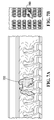
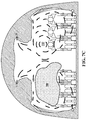
- a simulated passenger sneeze in a conventional aircraft not equipped with the present invention is shown generally at 700.
- some of the expelled pathogens of the sneeze 700 are propagated into the breathing areas of adjacent passengers in the same row, mainly by a general mixing airflow pattern 702, and also to a lesser extent by deflection off the convexly curved back of the seat in front of the passenger who sneezed.
- the general mixing airflow pattern 702 results from the configuration of the side and ceiling air inlets and of the near-floor baseboard air outlets of the conventional aircraft.
- the general mixing airflow pattern 702 also promotes very active longitudinal mixing, so that the pathogens also spread to passengers in nearby rows.
- a simulated passenger sneeze originating from the same seat in an aircraft equipped with redirectors 102 of the present embodiment is shown generally at 800.
- the first and second airflow portions 118 and 122 co-operate to effectively create an air curtain 802 between the window seat and middle seat, while the third airflow portion 126 and the airflow portion originating from the centre air inlet 132 combine to create an air curtain 804 in between the middle seat and aisle seat.
- the air curtains 802 and 804 and their associated stratified downward airflows tend to convey the pathogens downward toward the air outlets 130 instead of allowing them to recirculate in the breathing areas of the adjacent passengers in the same row; although some pathogens may still spread to the adjacent passengers, this tends to occur predominantly in the vicinity of the adjacent passengers' legs or waists, and not within the passengers' breathing areas.
- the stratified downward flows significantly inhibit longitudinal mixing, thereby inhibiting the ability of the pathogens to spread to nearby rows before being drawn out through the air outlets 130.
- the redirector may reduce pathogen inhalation by up to 98%, and may increase the proportion of inhaled air that is fresh air by over 190%.
- the redirector 102 as an airflow redirecting apparatus is readily apparent from the drawings and the above description, from which it is clear that the airflow 104 will be divided and redirected as described above. Accordingly, the redirector 102 is useful for that purpose even apart from any potential effect in reducing pathogens.
- the CFD simulations conducted by the present inventor have augmented the industry's understanding of pathogen propagation in airplane cabins.
- the present embodiment employs a high-fidelity simulation grid which resolves previously unseen flow features (3-5x).
- the present embodiment accounts for multiple phenomena including convection and turbulent flow.
- This embodiment also utilizes true-to-life cabin geometry, modelled using technical documents. Cabin air inlets & outlets are precisely placed, and statistically representative seated human mannequins have been created. Cabin airflows can be quantitatively and qualitatively analyzed from multiple perspectives.
- seating configurations may vary, namely a 3-3 configuration having 3 seats on each side of the centre aisle, in which each set is approximately 41 cm wide with a pitch of 82 cm, and the centre aisle is 51 cm wide, based on FAA regulatory specifications.
- ANSYS CFX code was selected as the Computational Fluid Dynamics numerical solver software for the simulation.
- the simulation method employed a coupled, fully implicit, pressure-based solver using an unstructured finite element based Finite Volume Method (FVM), using a vertex-centred approach involving polyhedral control volumes from tetrahedral cells.
- FVM Finite Volume Method
- a vertex-centred approach is typically better suited to achieving convergence of coarser meshes than a cell-centred method.
- the solutions are solved and stored at the nodes of the mesh, allowing for denser meshes.
- a specialized workstation was developed, using an 8-core 4GHz CPU with 32GB of RAM to enable resolution of fine CFD grids with more than 20 million cells.
- Various parallel processing techniques including GPGPU (general purpose graphics processing unit) acceleration of computations by using the GPU for non-specialized calculations that would typically be conducted by the CPU, and the local application of a suitable Message Passing Interface (MPI), enabled the CFD solution to be solved simultaneously on multiple cores.
- GPGPU general purpose graphics processing unit
- MPI Message Passing Interface
- CFD pre-processing was conducted for flow domain definition and discretization.
- CFD operates only on fluid regions, and thus the control volume must first be explicitly defined.
- the fluid domain can be extracted using CAD Boolean operations.
- the domain must be discretized to allow for a numerical solution.
- a primarily tetrahedral, patch-independent mesh scheme was employed, applying proximity and curvature-based grid refinement to preserve cabin integrity. Prism layers were applied at boundaries to better resolve flow features.
- Typical mesh quality standards for CFD were exceeded.
- high Orthogonal Quality greater than 0.01, and low Skewness, less than 0.95, were desired.
- the present embodiment sought to pioneer the finest resolution ever achieved for aircraft cabin airflow.
- most previous CFD work for aircraft cabins was based on about 3 million cells, and it is believed that no previously published CFD aircraft cabin study has employed more than 10 million cells.
- the simulations of the present embodiment employed aircraft cabin geometry that varied in cell count from 15-20 million elements.
- partitioning was applied to enable parallel processing for full CPU utilization in the solution calculation. More particularly, in this embodiment the industry standard MeTiS Multilevel Graph Partitioning Method was selected, employing 8 partitions with equal weighting (0.125).
- the CFD solver predicts cabin airflow by numerically converging solutions to the partial differential Navier-Stokes equations, which cannot be solved analytically. These equations are augmented with equations of state for enthalpy and density to form a closed system. For precision, the simulations implemented second-order discretization schemes of all transport equations.
- the ANSYS CFX CFD solver applies the instantaneous Navier-Stokes equations in conservation form.
- ⁇ represent a generic physical quantity (such as concentration, for example, although numerous other physical quantities such as temperature or velocity obey differential equations of the same form).
- the accumulation term represents the temporal rate of change of the quantity ⁇ in an infinitesimal volume.
- the convection term represents the transport of the quantity ⁇ due to the velocity field u .
- the diffusion term represents the transport of the quantity ⁇ due to gradients of that quantity.
- the source term S ⁇ collectively represents any sources or sinks that create or destroy the quantity ⁇ , and may also incorporate any further relevant terms that do not fit within the accumulation, convection or diffusion terms of equation (1).
- the ANSYS CFX CFD solver converges numerical solutions to the above equations, which are augmented with equations of state for enthalpy and density to form a closed system. More particularly, in this embodiment the CFD solver solves Reynolds Time-Averaged Navier Stokes (RANS) equations with turbulence modelling. More particularly still, in this embodiment the turbulence modelling employs a ReNormalization Group (RNG) k-epsilon model, in which k represents turbulence kinetic energy and epsilon (e) represents turbulence eddy dissipation.
- RNG ReNormalization Group
- Particle movement can be accounted for by the effects of drag and gravity. Additional terms for pressure gradients, Brownian motion, and the Saffman lift force were selected for inclusion to mimic actual physical conditions. To eliminate unnecessary computational cost, one-way coupling of the air and particles was employed, whereby the particle sizes are assumed to be too insignificant to influence the movement of air.
- boundary conditions were specified for all the fluid inlets and outlets in the computational domain. Referencing existing measurements,[12] the inlet and outlet conditions were modelled as described below. As is standard practice in these scenarios [CT], a turbulence intensity of 10% with the "high" eddy viscosity ratio setting was used for all inlets. With respect to boundary conditions, velocity inlet & pressure outlet pairing is viewed as the most stable numerical configuration method.
- an inlet flow velocity of 3 m/s is assumed for the centre air inlets 132 shown in Figure 6
- an inlet flow velocity of 2.7 m/s is assumed for the side air inlets 106.
- the incoming airflow is normal to the boundary.
- a sneezing passenger is considered to effectively act as a "passenger inlet” for pathogens.
- a "passenger inlet” is defined as a single mass flow for pathogens.
- the bulk mass flow rate was set to 0.0000318 [kg s ⁇ -1] normal to the boundary, using empirical data for sneezes obtained from previous literature.
- Buoyancy was modelled with a Boussinesq assumption, whereby the small range of temperature variations in the cabin render density differences of air sufficiently small to be neglected, except where gravity terms are considered.
- a full buoyancy model was unnecessary due to the typically small magnitude of temperature fluctuations in aircraft cabins.
- a buoyancy reference density of 0.877566 kg m/s 3 and a buoyancy reference temperature of 21 °C were employed.
- these thermal phenomena interact with gravity, and thus in this embodiment a gravitational acceleration of -9.81 m/s 2 was involved in the modelling of convection.
- the cabin domain was specified as initially consisting of 100% air at a typical at-altitude reference pressure of 74100 Pa,[13] with a nominal cabin temperature of 21 °C.[11]
- the CFD solver results indicate that the redirector 102 of the present embodiment reduces pathogen transmission.
- a simulated passenger sneeze in a conventional aircraft cabin is shown generally at 700 in Figures 7A to 7C
- a simulated passenger sneeze in an aircraft cabin that has been modified to include a plurality of redirectors 102 according to the present embodiment is shown generally at 800 in Figures 8A to 8C .
- the passenger who sneezed occupied a middle seat position, which in these examples was seat 4E (see also Figure 10 ).
- Figures 7A and 8A illustrates that in the modified cabin of Figures 8A-8C , the improved and stratified airflow pattern tends to more effectively confine the expelled pathogens to the row of the sneezing passenger than in the conventional cabin of Figures 7A-7C .
- Figure 9 shows the percentage of inhaled air that is fresh air (as opposed to recirculated air), for each of the six seating columns A through F (see also Figure 10 ). More particularly, Figure 9 shows a time-snapshot taken from a transient simulation rather than time-averaged results.
- the left fresh air column represents the inhaled fresh air percentage for a conventional aircraft cabin
- the right fresh air column represents the inhaled fresh air percentage for a modified aircraft cabin equipped with a plurality of redirectors 102. It can be seen that for the modified cabin, the fresh air percentage increases for all six of the seating columns, and more than doubles for seating columns A, B, D and F. Consequently, it is expected that passengers will breathe significantly more fresh air and less recirculated air in a cabin equipped with redirectors 102 than in a cabin that is not so equipped.
- FIG. 10 pathogen concentrations as a volumetric fraction are shown for the same two situations as Figures 7A-8C , in which a passenger in seat 4E sneezes in a traditional or conventional cabin not equipped with redirectors 102, and in which a passenger in the same seat sneezes in a modified cabin equipped with redirectors 102.
- a conventional curve 1000 shows the resulting pathogen concentration at the adjacent passenger aisle seat 4D of the conventional aircraft, while an improved curve 1002 shows the resulting pathogen concentration at the same seat 4D of the modified aircraft equipped with redirectors 102.
- a conventional curve 1004 shows the resulting pathogen concentration at the adjacent passenger window seat 4F of the conventional aircraft, while an improved curve 1006 shows the resulting pathogen concentration at the same seat 4F of the modified aircraft equipped with redirectors 102. Similar contrasting curves for other seating positions are also shown in Figure 10 .
- a conventional average curve 1008 shows the average pathogen concentration for all of the considered seating positions for the conventional aircraft, while a modified average curve 1010 shows the average pathogen concentration for a modified aircraft equipped with redirectors 102.
- Figures 7A-8C and 10 simulated a sneeze originating from a middle passenger seat position (seat 4E)
- FIG. 11 a simulated sneeze from a window seat position (seating column F) is shown generally at 1100
- Figure 12 a simulated sneeze from an aisle seat position (seating column D) is shown generally at 1200.
- the modified and stratified airflow patterns created by the redirectors 102 tended to achieve similar advantageous effects to those illustrated in Figures 8A and 8B in comparison to the conventional aircraft of Figures 7A and 7B .
- 3:40 scale models of a conventional narrow-bodied aircraft cabin section and of a modified aircraft cabin section equipped with redirectors 102 were constructed from 3D printed translucent resin. Both models were of the same type of aircraft for which the CFD results described above were obtained.
- redirector 102 Although a specific shape of the redirector 102 has been shown in Figures 1-6 , alternatively other forms of redirector may be substituted. The shape shown in Figures 1-6 is generally preferred for aircraft with non-slot-type air inlets. However, for aircraft having slot-type air inlets, other shapes of the redirector 102 may be more advantageous.
- an apparatus according to a second embodiment of the invention is shown generally at 1300.
- the apparatus 1300 includes a first redirector 1302, which in turn comprises an elongated protrusion configured to be positioned on the ceiling 128 of the aircraft cabin 108.
- the elongated first redirector 1302 extends longitudinally along the ceiling 128 of the cabin 108.
- the first redirector 1302 has rounded opposing outside and inside sidewalls 1304 and 1306, which extend vertically downward from the ceiling 128 of the cabin 108 while curving inward toward each other until intersecting a horizontal planar bottom surface 1308. Also in this embodiment, in addition to the curved outside and inside sidewalls 1304 and 1306, the forward and aft ends of the first redirector 1302 are also smoothly rounded with no sharp edges. Advantageously, therefore, if a passenger accidentally contacts their head against the first redirector 1302, it will contact against a smooth rounded surface rather than a sharp edged surface, thereby reducing the risk of injury.
- the apparatus 1300 further includes a second redirector 1310.
- the second redirector 1310 is identical to the first redirector 1302, and thus includes curved opposing outside and inside sidewalls 1312 and 1314 and a planar bottom surface 1316.
- the second redirector 1310 is mounted along the ceiling 128 of the cabin 108 parallel to but spaced apart from the first redirector 1302. More particularly, in this embodiment the first redirector 1302 is mounted at a location on the ceiling 128 between the window seat and the middle seat, while the second redirector 1310 is mounted at a location on the ceiling 128 between the middle seat and the aisle seat.
- first and second redirectors 1302 and 1310 are each shown as a unitary structure, alternatively the redirectors 1302 and 1310 may be modularly segmented, for ease of installation and to accommodate other items (e.g. speakers, no smoking signs, passenger service units, etc.) that may be present on the cabin ceiling.
- other items e.g. speakers, no smoking signs, passenger service units, etc.
- the first and second redirectors 1302 and 1310 are composed of polycarbonate. However, due to the placement of the first and second redirectors 1302 and 1310 along the ceiling 128 of the cabin 108, the first and second redirectors 1302 and 1310 are not as prone to blocking cabin light as the redirectors 102. Accordingly, in this embodiment the first and second redirectors 1302 and 1310 are composed of opaque white polycarbonate with an optional secondary accent colour which makes the redirectors easily visible to passengers and thus reduces the risk of passengers bumping their heads on the redirectors, while simultaneously blending with the aesthetics of the cabin. Alternatively, if desired, the first and second redirectors 1302 and 1310 may be composed of translucent white polycarbonate, or optically transparent polycarbonate. More generally, any other suitable material may be substituted, provided it has sufficient flame retardant properties to be permitted as an aircraft cabin component. If desired, the first and second redirectors 1302 and 1310 may be hollow, to reduce weight.
- a plurality of the first redirectors 1302 and a plurality of the second redirectors 1310 extend longitudinally over a distance equal to the longitudinal length of the entire aircraft cabin, modularly implemented such that each unit, i.e. each pair of redirectors, is responsible for a respective air inlet section of the aircraft containing the air inlet 106 (typically two seating rows long).
- each one of the plurality of air inlet sections of the aircraft, containing each respective one of the air inlets 106 of the aircraft is equipped with a similar pair of first and second redirectors.
- Each such pair of first and second redirectors is generally identical to the pair of first and second redirectors 1302 and 1310, except insofar as the length of a given air inlet section and thus the length of the corresponding pair of first and second redirectors may vary.
- the air inlets for the emergency exit rows may have a different air inlet length than other air inlet sections of the aircraft.
- the first redirector 1302 is configured to divide the incoming airflow 104 from the air inlet 106 into at least a first airflow portion 1320 flowing downwardly along one side of the redirector 1302 and a second airflow portion 1322 flowing along an opposite side of the redirector. More particularly, in this embodiment the incoming airflow 104 tends to initially follow the contour of the cabin ceiling 128 by virtue of the Coanda effect. As the airflow 104 travels inward along the ceiling 128, it first strikes the outside sidewall 1304 of the redirector 1302. As the airflow 104 strikes the sidewall 1304 of the redirector 1302, the sidewall 1304 downwardly redirects the first airflow portion 1320 of the incoming airflow 104, as shown in Figure 13 .
- the second airflow portion 1322 of the incoming airflow 104 tends to follow the contours of the redirector 1302, travelling inward along the bottom surface 1308 and then back upward along the inside sidewall 1306 and inwardly along the ceiling 128 of the cabin 108.
- the second redirector 1310 effectively further divides the second airflow portion 1322 into a third airflow portion 1324 and a fourth airflow portion 1326 shown in Figure 13 .
- the second airflow portion 1322 travels inward along the ceiling 128, it strikes the outside sidewall 1312 of the second redirector 1310, which downwardly redirects some of the incoming second airflow portion 1322, as the third airflow portion 1324.
- the remaining portion of the second airflow portion 1322 becomes the fourth airflow portion 1326, which tends to follow the contours of the second redirector 1310, continuing to travel inward within the cabin 108.
- an additional airflow portion 1328 from the aircraft cabin's central ceiling inlets tends to follow the contours of the underneath of the overhead luggage compartments and may thus collide with the fourth airflow portion 1326, thereby redirecting some of the fourth airflow portion 1326 downward as well.
- this second embodiment tends to produce a stratified downward airflow pattern somewhat similar to that produced by the first embodiment, with similar effects.
- first and second redirectors 1302 and 1310 are generally preferable for aircraft having slot-type air inlets such as those depicted in Figures 13 and 14 , they can also be used with non-slot-type air inlets as shown in Figures 5 and 6 .
- the redirector 102 of Figures 1-6 is generally preferable for aircraft having non-slot-type inlets, it can also be employed in aircraft having slot-type air inlets.
- either or both of the first and second redirectors 1302 and 1310 may include a plurality of long or short slots or other apertures (not shown) defined therethrough to further improve the airflow pattern for a particular aircraft.
- the first redirector 1302 has a plurality of slots defined therethrough, such that an additional airflow portion (not shown) travels through the slots of the first redirector 1302 and flows along with the second airflow portion 1322 to ultimately strike the inlet-facing sidewall 1312 of the second redirector 1310, and to thereby increase the flow of fresh air available at the second redirector 1310 for forming the downward third airflow portion 1324.
- an alternatively shaped redirector may include a planar redirector with a plurality of openings, such as slots or apertures, defined therethrough.
- the planar redirector may be installed at an angle relative to the incoming airflow 104 somewhat similar to the angle of the redirecting portion 112 of the redirector 102, such that the portions of the incoming airflow that strike the solid portions of the planar redirector are directed downwardly, similar to the first and second airflow portions 118 and 122, while the remaining portions of the incoming airflow 104 that either bypass the outside of the planar redirector or travel through the openings in the planar redirector travel along the aircraft ceiling similar to the third airflow portion 126.
- a two-plate redirector may be provided with two such plates spaced apart from each other.
- the upstream plate redirects a first portion of the incoming airflow downward similar to the first airflow portion 118, and permits a second portion to travel through its openings to the downstream plate.
- the downstream plate similarly redirects part of the second portion of the air received from the upstream plate in a downward direction, similar to the second airflow portion 122, and permits the remainder of the second portion to travel through its openings to then travel along the cabin ceiling similar to the third airflow portion 126.
- the downstream plate and the upstream plate need not be parallel but may be angled relative to each other, similar to the angle between the opposing surfaces 120 and 124 of the redirecting portion 112 of the redirector 102.
- some embodiments permit adjustment of the angle at which the redirecting portion downwardly directs the portion of the airflow.
- the redirector itself is rigid but pivotally adjustable, so that the installation angle of the entire redirector 102 may be varied as needed in order to provide the desired stratification of airflows.
- the redirecting portion may be pivotally adjustable relative to the dividing portion, as discussed below.
- the redirector is adjustably attachable to the existing aircraft to permit adjustment of an angle at which the redirector downwardly directs the portion of the airflow.
- the redirectors may instead be attached to a pivotally adjustable mounting mechanism attached to each sidewall portion.
- pivots may be provided at the points of attachment of the redirectors to the screws that attach it to the cabin ceiling.
- each redirector is resiliently attachable to the existing aircraft. More particularly, in an alternative embodiment, each redirector is attached to a spring-loaded pivot mechanism that permits the rounded downstream edge 116 to resiliently pivot if a passenger's head inadvertently bumps against the downstream edge 116.
- each side of the redirector may instead be attached to a mounting disk containing a coiled spring, which permits resilient pivotal movement of the face of the disk to which each side of the redirector is mounted.
- resilient pivots may be provided at the points of attachment of the redirectors to the screws that attach it to the cabin ceiling.
- the resilient pivot mechanism may be provided as part of an adjustable-angle pivot mechanism.
- resilient attachment may also be provided in embodiments that lack adjustable attachment, and vice versa.
- an attachment mechanism for attaching the redirector 102 to an aircraft cabin is shown generally at 1500.
- the attachment mechanism 1500 includes a resilient and adjustable attachment mechanism configured to resiliently and adjustably attach the redirector 102 to an existing aircraft to permit adjustment of an angle at which the redirector downwardly directs the first airflow portion 118 (see Figure 6 ).
- the attachment mechanism 1500 includes a pivoting mechanism 1502 and a mounting plate 1504.
- the pivoting mechanism 1502 includes a spring-loaded disk that permits one of its faces to resiliently pivot relative to its other opposing face.
- the pivoting mechanism 1502 includes screwholes 1506 to accommodate screws (not shown) for rigidly mounting one face of the pivoting mechanism 1502 to a radially extending sidewall portion that defines one of the longitudinal boundaries of the air inlet section in which the redirector 102 is to be mounted.
- the mounting plate 1504 is oblong and includes a first plurality of screwholes 1508 to accommodate screws (not shown) for attaching the mounting plate 1504 to the redirector 102, and a second plurality of screwholes 1510 to accommodate screws (not shown) for attaching the mounting plate 1504 to the pivoting mechanism 1502.
- any pair of the screwholes 1508 may be selected, to thereby adjust and control the resting (normal) angle of inclination of the redirector 102.
- the damping force and spring rate of the spring-loaded pivoting mechanism 1502 are preferably selected to prevent or minimize movement under turbulence or ordinary operating conditions, and to permit resilient pivotal movement under larger forces, such as if bumped by a passenger for example. It will be appreciated that the depicted shapes and configurations of the components of the attachment mechanism 1500 are merely illustrative.
- the mounting plate 1504 and pivoting mechanism 1502 need not have strictly cylindrical shapes or profiles across the entire length of the redirector, but may instead possess non-planar forward and aft faces, particularly at the two points of contact between the mounting device and the curved cabin sidewall surface, such that the surface is in a sense complementary in shape to the curved cabin sidewall surface at or near the point of attachment, so as to more securely attach the redirecting device.
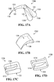
- a redirector according to a third embodiment of the invention is shown generally at 1700.
- the redirector 1700 includes a dividing portion 1702 and a redirecting portion shown generally at 1704. More particularly, in this embodiment the redirecting portion 1704 includes a lower redirecting portion 1706 and an upper redirecting portion 1708.
- the dividing portion 1702 is similar to the dividing portion 110 shown in Figures 1-6 , except that it includes an additional screwhole 1710 for pivotal attachment to the redirecting portion 1704, or more particularly for pivotal attachment to the lower and upper redirecting portions 1706 and 1708, which have respective screwholes 1712 and 1714 for accommodating the same elongated screw.
- the upper redirecting portion 1708 includes an inward-facing protrusion 1716, which is engageable within a complementary recess 1718 of the lower redirecting portion 1706.
- An elongated screw (not shown) is insertable through the screwhole 1710 at the front of the dividing portion 1702, then through the screwhole 1712 at the front of the lower redirecting portion 1706, then through the screwhole 1714 of the upper redirecting portion 1708, then through the screwhole 1712 at the rear of the lower redirecting portion 1706, and finally into threaded engagement with threads (not shown) of the screwhole 1710 at the rear of the dividing portion 1702.
- the screw is first inserted into the screwholes as described above but is only partly tightened to provide a modest but surmountable amount of friction to facilitate manual adjustment.
- the lower redirecting portion 1706 is then manually pivoted about the screw to the desired angle relative to the dividing portion 1702.
- the angle between the lower surface 120 and the upper surface 124 of the redirector 1700 may also be varied at this time, by manually pivoting the upper redirecting portion 1708 about the screw, relative to the lower redirecting portion 1706.
- the screw is further tightened so that the protrusion 1716 of the upper redirecting portion 1708 is firmly squeezed and held by friction in the recess 1718 of the lower redirecting portion 1706, thereby preventing further pivotal movement of the lower and upper redirecting portions relative to the dividing portion.
- the relative angles among any of the lower and upper surfaces 120 and 124 of the redirecting portion 112, and the dividing portion 110 may be varied.
- the angle between the redirecting portion 112 and the dividing portion 110 may be customized at the point of manufacture to fit the proportions of the aircraft cabin.
- embodiments of the present invention are not limited to any particular brand of aircraft or to any particular type of aircraft.
- embodiments may be equally useful for wide bodied (twin aisle) aircraft. More broadly, embodiments may also be useful for other types of transportation vehicles such as trains or buses, or for enclosed public spaces such as waiting rooms.
- the results obtained and discussed above for narrow-bodied aircraft may fairly be extrapolated to other such vehicles or spaces that have top and/or side air inlets and bottom mounted air outlets.
- each redirector may be formed in a modular fashion by joining a plurality of prefabricated redirector sections together.
- such sections may be joined using a resin or glue, which is preferably transparent if the redirector sections are transparent.
- the prefabricated redirector sections may be formed with interlocking complementary male and female connectors, so that the male connector of each redirector section may be inserted and locked into the female connector of an adjacent redirector section.
- other ways of joining redirector sections together may be substituted.
Landscapes
- Engineering & Computer Science (AREA)
- Physics & Mathematics (AREA)
- Geometry (AREA)
- Theoretical Computer Science (AREA)
- General Physics & Mathematics (AREA)
- Aviation & Aerospace Engineering (AREA)
- Evolutionary Computation (AREA)
- General Engineering & Computer Science (AREA)
- Computer Hardware Design (AREA)
- Mechanical Engineering (AREA)
- Thermal Sciences (AREA)
- General Health & Medical Sciences (AREA)
- Health & Medical Sciences (AREA)
- Pulmonology (AREA)
- Pure & Applied Mathematics (AREA)
- Mathematical Optimization (AREA)
- Mathematical Analysis (AREA)
- Computational Mathematics (AREA)
- Automation & Control Theory (AREA)
- Duct Arrangements (AREA)
Applications Claiming Priority (1)
| Application Number | Priority Date | Filing Date | Title |
|---|---|---|---|
| US201562158889P | 2015-05-08 | 2015-05-08 |
Publications (1)
| Publication Number | Publication Date |
|---|---|
| EP3090948A1 true EP3090948A1 (de) | 2016-11-09 |
Family
ID=55919696
Family Applications (1)
| Application Number | Title | Priority Date | Filing Date |
|---|---|---|---|
| EP16168552.4A Withdrawn EP3090948A1 (de) | 2015-05-08 | 2016-05-06 | Luftstrommodifizierungsvorrichtung und verfahren |
Country Status (3)
| Country | Link |
|---|---|
| US (1) | US9725178B2 (de) |
| EP (1) | EP3090948A1 (de) |
| CA (1) | CA2929340A1 (de) |
Cited By (4)
| Publication number | Priority date | Publication date | Assignee | Title |
|---|---|---|---|---|
| US11144685B2 (en) | 2018-09-12 | 2021-10-12 | AGC Inc. | Simulation method, simulation method by MBD program, numerical analysis apparatus, numerical analysis system for MBD, numerical analysis program, and MBD program |
| EP3960630A1 (de) * | 2020-08-28 | 2022-03-02 | The Boeing Company | Luftschleiersysteme und -verfahren für fahrzeugkabinen |
| EP3971088A1 (de) * | 2020-09-21 | 2022-03-23 | B/E Aerospace, Inc. | Luftstromverwaltung |
| GB2634112A (en) * | 2023-09-21 | 2025-04-02 | Airbus Sas | Aircraft cabin air distribution system |
Families Citing this family (114)
| Publication number | Priority date | Publication date | Assignee | Title |
|---|---|---|---|---|
| KR20170019366A (ko) | 2014-05-16 | 2017-02-21 | 디버전트 테크놀로지스, 인크. | 차량 섀시용 모듈형 성형 접속체 및 그 사용 방법 |
| JP6820843B2 (ja) | 2014-07-02 | 2021-01-27 | ダイバージェント テクノロジーズ, インコーポレイテッドDivergent Technologies, Inc. | 継手部材を製造するためのシステム及び方法 |
| US20170232815A1 (en) * | 2016-02-11 | 2017-08-17 | Kenneth S Deneau | Vehicle hvac outlet and grille elements |
| US10173255B2 (en) | 2016-06-09 | 2019-01-08 | Divergent Technologies, Inc. | Systems and methods for arc and node design and manufacture |
| US10759090B2 (en) | 2017-02-10 | 2020-09-01 | Divergent Technologies, Inc. | Methods for producing panels using 3D-printed tooling shells |
| US11155005B2 (en) | 2017-02-10 | 2021-10-26 | Divergent Technologies, Inc. | 3D-printed tooling and methods for producing same |
| US12251884B2 (en) | 2017-04-28 | 2025-03-18 | Divergent Technologies, Inc. | Support structures in additive manufacturing |
| US10898968B2 (en) | 2017-04-28 | 2021-01-26 | Divergent Technologies, Inc. | Scatter reduction in additive manufacturing |
| US10703419B2 (en) | 2017-05-19 | 2020-07-07 | Divergent Technologies, Inc. | Apparatus and methods for joining panels |
| US11358337B2 (en) | 2017-05-24 | 2022-06-14 | Divergent Technologies, Inc. | Robotic assembly of transport structures using on-site additive manufacturing |
| US11123973B2 (en) | 2017-06-07 | 2021-09-21 | Divergent Technologies, Inc. | Interconnected deflectable panel and node |
| US10919230B2 (en) | 2017-06-09 | 2021-02-16 | Divergent Technologies, Inc. | Node with co-printed interconnect and methods for producing same |
| US10781846B2 (en) | 2017-06-19 | 2020-09-22 | Divergent Technologies, Inc. | 3-D-printed components including fasteners and methods for producing same |
| US10994876B2 (en) | 2017-06-30 | 2021-05-04 | Divergent Technologies, Inc. | Automated wrapping of components in transport structures |
| US11022375B2 (en) | 2017-07-06 | 2021-06-01 | Divergent Technologies, Inc. | Apparatus and methods for additively manufacturing microtube heat exchangers |
| US10895315B2 (en) | 2017-07-07 | 2021-01-19 | Divergent Technologies, Inc. | Systems and methods for implementing node to node connections in mechanized assemblies |
| US10940609B2 (en) | 2017-07-25 | 2021-03-09 | Divergent Technologies, Inc. | Methods and apparatus for additively manufactured endoskeleton-based transport structures |
| US10751800B2 (en) | 2017-07-25 | 2020-08-25 | Divergent Technologies, Inc. | Methods and apparatus for additively manufactured exoskeleton-based transport structures |
| US10605285B2 (en) | 2017-08-08 | 2020-03-31 | Divergent Technologies, Inc. | Systems and methods for joining node and tube structures |
| US10357959B2 (en) | 2017-08-15 | 2019-07-23 | Divergent Technologies, Inc. | Methods and apparatus for additively manufactured identification features |
| US11306751B2 (en) | 2017-08-31 | 2022-04-19 | Divergent Technologies, Inc. | Apparatus and methods for connecting tubes in transport structures |
| US10960611B2 (en) | 2017-09-06 | 2021-03-30 | Divergent Technologies, Inc. | Methods and apparatuses for universal interface between parts in transport structures |
| US11292058B2 (en) | 2017-09-12 | 2022-04-05 | Divergent Technologies, Inc. | Apparatus and methods for optimization of powder removal features in additively manufactured components |
| US10668816B2 (en) | 2017-10-11 | 2020-06-02 | Divergent Technologies, Inc. | Solar extended range electric vehicle with panel deployment and emitter tracking |
| US10814564B2 (en) | 2017-10-11 | 2020-10-27 | Divergent Technologies, Inc. | Composite material inlay in additively manufactured structures |
| US11786971B2 (en) | 2017-11-10 | 2023-10-17 | Divergent Technologies, Inc. | Structures and methods for high volume production of complex structures using interface nodes |
| US10926599B2 (en) | 2017-12-01 | 2021-02-23 | Divergent Technologies, Inc. | Suspension systems using hydraulic dampers |
| US11110514B2 (en) | 2017-12-14 | 2021-09-07 | Divergent Technologies, Inc. | Apparatus and methods for connecting nodes to tubes in transport structures |
| WO2019119115A1 (en) * | 2017-12-18 | 2019-06-27 | Bombardier Inc. | Overhead flow distribution assembly for aircraft cabin |
| US11085473B2 (en) | 2017-12-22 | 2021-08-10 | Divergent Technologies, Inc. | Methods and apparatus for forming node to panel joints |
| US11534828B2 (en) | 2017-12-27 | 2022-12-27 | Divergent Technologies, Inc. | Assembling structures comprising 3D printed components and standardized components utilizing adhesive circuits |
| US11420262B2 (en) | 2018-01-31 | 2022-08-23 | Divergent Technologies, Inc. | Systems and methods for co-casting of additively manufactured interface nodes |
| US10751934B2 (en) | 2018-02-01 | 2020-08-25 | Divergent Technologies, Inc. | Apparatus and methods for additive manufacturing with variable extruder profiles |
| US11224943B2 (en) | 2018-03-07 | 2022-01-18 | Divergent Technologies, Inc. | Variable beam geometry laser-based powder bed fusion |
| US11267236B2 (en) | 2018-03-16 | 2022-03-08 | Divergent Technologies, Inc. | Single shear joint for node-to-node connections |
| US11254381B2 (en) | 2018-03-19 | 2022-02-22 | Divergent Technologies, Inc. | Manufacturing cell based vehicle manufacturing system and method |
| US11872689B2 (en) | 2018-03-19 | 2024-01-16 | Divergent Technologies, Inc. | End effector features for additively manufactured components |
| US11408216B2 (en) | 2018-03-20 | 2022-08-09 | Divergent Technologies, Inc. | Systems and methods for co-printed or concurrently assembled hinge structures |
| US11613078B2 (en) | 2018-04-20 | 2023-03-28 | Divergent Technologies, Inc. | Apparatus and methods for additively manufacturing adhesive inlet and outlet ports |
| US11214317B2 (en) | 2018-04-24 | 2022-01-04 | Divergent Technologies, Inc. | Systems and methods for joining nodes and other structures |
| US10682821B2 (en) | 2018-05-01 | 2020-06-16 | Divergent Technologies, Inc. | Flexible tooling system and method for manufacturing of composite structures |
| US11020800B2 (en) | 2018-05-01 | 2021-06-01 | Divergent Technologies, Inc. | Apparatus and methods for sealing powder holes in additively manufactured parts |
| US11389816B2 (en) | 2018-05-09 | 2022-07-19 | Divergent Technologies, Inc. | Multi-circuit single port design in additively manufactured node |
| US10691104B2 (en) | 2018-05-16 | 2020-06-23 | Divergent Technologies, Inc. | Additively manufacturing structures for increased spray forming resolution or increased fatigue life |
| US11590727B2 (en) | 2018-05-21 | 2023-02-28 | Divergent Technologies, Inc. | Custom additively manufactured core structures |
| US11441586B2 (en) | 2018-05-25 | 2022-09-13 | Divergent Technologies, Inc. | Apparatus for injecting fluids in node based connections |
| US11035511B2 (en) | 2018-06-05 | 2021-06-15 | Divergent Technologies, Inc. | Quick-change end effector |
| CN111742181B (zh) * | 2018-06-14 | 2023-02-28 | 松下知识产权经营株式会社 | 信息处理方法、信息处理系统以及记录介质 |
| CN111837000A (zh) | 2018-06-28 | 2020-10-27 | 松下知识产权经营株式会社 | 飞沫感染抑制系统以及飞沫感染抑制方法 |
| US11292056B2 (en) | 2018-07-06 | 2022-04-05 | Divergent Technologies, Inc. | Cold-spray nozzle |
| US11269311B2 (en) | 2018-07-26 | 2022-03-08 | Divergent Technologies, Inc. | Spray forming structural joints |
| US10836120B2 (en) | 2018-08-27 | 2020-11-17 | Divergent Technologies, Inc . | Hybrid composite structures with integrated 3-D printed elements |
| US11433557B2 (en) | 2018-08-28 | 2022-09-06 | Divergent Technologies, Inc. | Buffer block apparatuses and supporting apparatuses |
| US11826953B2 (en) | 2018-09-12 | 2023-11-28 | Divergent Technologies, Inc. | Surrogate supports in additive manufacturing |
| US11072371B2 (en) | 2018-10-05 | 2021-07-27 | Divergent Technologies, Inc. | Apparatus and methods for additively manufactured structures with augmented energy absorption properties |
| US11260582B2 (en) | 2018-10-16 | 2022-03-01 | Divergent Technologies, Inc. | Methods and apparatus for manufacturing optimized panels and other composite structures |
| US12115583B2 (en) | 2018-11-08 | 2024-10-15 | Divergent Technologies, Inc. | Systems and methods for adhesive-based part retention features in additively manufactured structures |
| US12194536B2 (en) | 2018-11-13 | 2025-01-14 | Divergent Technologies, Inc. | 3-D printer with manifolds for gas exchange |
| US11504912B2 (en) | 2018-11-20 | 2022-11-22 | Divergent Technologies, Inc. | Selective end effector modular attachment device |
| USD911222S1 (en) | 2018-11-21 | 2021-02-23 | Divergent Technologies, Inc. | Vehicle and/or replica |
| US10663110B1 (en) | 2018-12-17 | 2020-05-26 | Divergent Technologies, Inc. | Metrology apparatus to facilitate capture of metrology data |
| US11529741B2 (en) | 2018-12-17 | 2022-12-20 | Divergent Technologies, Inc. | System and method for positioning one or more robotic apparatuses |
| US11449021B2 (en) | 2018-12-17 | 2022-09-20 | Divergent Technologies, Inc. | Systems and methods for high accuracy fixtureless assembly |
| US11885000B2 (en) | 2018-12-21 | 2024-01-30 | Divergent Technologies, Inc. | In situ thermal treatment for PBF systems |
| US12378643B2 (en) | 2019-01-18 | 2025-08-05 | Divergent Technologies, Inc. | Aluminum alloys |
| US11203240B2 (en) | 2019-04-19 | 2021-12-21 | Divergent Technologies, Inc. | Wishbone style control arm assemblies and methods for producing same |
| US12314031B1 (en) | 2019-06-27 | 2025-05-27 | Divergent Technologies, Inc. | Incorporating complex geometric features in additively manufactured parts |
| US12280554B2 (en) | 2019-11-21 | 2025-04-22 | Divergent Technologies, Inc. | Fixtureless robotic assembly |
| US11912339B2 (en) | 2020-01-10 | 2024-02-27 | Divergent Technologies, Inc. | 3-D printed chassis structure with self-supporting ribs |
| US11590703B2 (en) | 2020-01-24 | 2023-02-28 | Divergent Technologies, Inc. | Infrared radiation sensing and beam control in electron beam additive manufacturing |
| US12194674B2 (en) | 2020-02-14 | 2025-01-14 | Divergent Technologies, Inc. | Multi-material powder bed fusion 3-D printer |
| US11884025B2 (en) | 2020-02-14 | 2024-01-30 | Divergent Technologies, Inc. | Three-dimensional printer and methods for assembling parts via integration of additive and conventional manufacturing operations |
| US11479015B2 (en) | 2020-02-14 | 2022-10-25 | Divergent Technologies, Inc. | Custom formed panels for transport structures and methods for assembling same |
| US12203397B2 (en) | 2020-02-18 | 2025-01-21 | Divergent Technologies, Inc. | Impact energy absorber with integrated engine exhaust noise muffler |
| US11535322B2 (en) | 2020-02-25 | 2022-12-27 | Divergent Technologies, Inc. | Omni-positional adhesion device |
| US11421577B2 (en) | 2020-02-25 | 2022-08-23 | Divergent Technologies, Inc. | Exhaust headers with integrated heat shielding and thermal syphoning |
| US12337541B2 (en) | 2020-02-27 | 2025-06-24 | Divergent Technologies, Inc. | Powder bed fusion additive manufacturing system with desiccant positioned within hopper and ultrasonic transducer |
| US11413686B2 (en) | 2020-03-06 | 2022-08-16 | Divergent Technologies, Inc. | Methods and apparatuses for sealing mechanisms for realizing adhesive connections with additively manufactured components |
| US20210387737A1 (en) * | 2020-06-10 | 2021-12-16 | Walter Dorwin Teague Associates, Inc. | Passenger air shield |
| KR20230035571A (ko) | 2020-06-10 | 2023-03-14 | 디버전트 테크놀로지스, 인크. | 적응형 생산 시스템 |
| US12151820B2 (en) * | 2020-06-18 | 2024-11-26 | B/E Aerospace, Inc. | Software controlled air flow management |
| USD984255S1 (en) * | 2020-06-18 | 2023-04-25 | Pexco Aerospace, Inc. | Air redirector mount |
| US12187440B2 (en) | 2020-07-02 | 2025-01-07 | The Boeing Company | Air curtain systems and methods for internal cabins of vehicles |
| WO2022026382A1 (en) | 2020-07-27 | 2022-02-03 | Auburn University | Serviceable respirator system with configurable components |
| US11850804B2 (en) | 2020-07-28 | 2023-12-26 | Divergent Technologies, Inc. | Radiation-enabled retention features for fixtureless assembly of node-based structures |
| US12492834B2 (en) * | 2020-08-19 | 2025-12-09 | Hcl Technologies Limited | Device and system for creating air capsules around passengers in vehicles and method thereof |
| US11806941B2 (en) | 2020-08-21 | 2023-11-07 | Divergent Technologies, Inc. | Mechanical part retention features for additively manufactured structures |
| CN116457139A (zh) | 2020-09-08 | 2023-07-18 | 戴弗根特技术有限公司 | 组装顺序生成 |
| CN116669885A (zh) | 2020-09-22 | 2023-08-29 | 戴弗根特技术有限公司 | 用于球磨以生产用于增材制造的粉末的方法和设备 |
| US12220819B2 (en) | 2020-10-21 | 2025-02-11 | Divergent Technologies, Inc. | 3-D printed metrology feature geometry and detection |
| DE102020128368A1 (de) | 2020-10-28 | 2022-04-28 | Airbus Operations Gmbh | Fahrzeugbereich mit im Kopfbereich angeordnetem Luftauslass und Fahrzeug mit mindestens einem Fahrzeugbereich |
| US12311612B2 (en) | 2020-12-18 | 2025-05-27 | Divergent Technologies, Inc. | Direct inject joint architecture enabled by quick cure adhesive |
| US12083596B2 (en) | 2020-12-21 | 2024-09-10 | Divergent Technologies, Inc. | Thermal elements for disassembly of node-based adhesively bonded structures |
| US12226824B2 (en) | 2020-12-22 | 2025-02-18 | Divergent Technologies, Inc. | Three dimensional printer with configurable build plate for rapid powder removal |
| US11872626B2 (en) | 2020-12-24 | 2024-01-16 | Divergent Technologies, Inc. | Systems and methods for floating pin joint design |
| US11947335B2 (en) | 2020-12-30 | 2024-04-02 | Divergent Technologies, Inc. | Multi-component structure optimization for combining 3-D printed and commercially available parts |
| US11928966B2 (en) | 2021-01-13 | 2024-03-12 | Divergent Technologies, Inc. | Virtual railroad |
| US12459377B2 (en) | 2021-01-19 | 2025-11-04 | Divergent Technologies, Inc. | Energy unit cells for primary vehicle structure |
| US12249812B2 (en) | 2021-01-19 | 2025-03-11 | Divergent Technologies, Inc. | Bus bars for printed structural electric battery modules |
| CN114963490B (zh) * | 2021-02-19 | 2023-05-16 | 青岛海尔空调器有限总公司 | 导风板以及具有其的壁挂式空调室内机 |
| CN114963328B (zh) * | 2021-02-19 | 2023-05-16 | 青岛海尔空调器有限总公司 | 壁挂式空调室内机 |
| US20220288850A1 (en) | 2021-03-09 | 2022-09-15 | Divergent Technologies, Inc. | Rotational additive manufacturing systems and methods |
| US12090551B2 (en) | 2021-04-23 | 2024-09-17 | Divergent Technologies, Inc. | Removal of supports, and other materials from surface, and within hollow 3D printed parts |
| US12138772B2 (en) | 2021-04-30 | 2024-11-12 | Divergent Technologies, Inc. | Mobile parts table |
| CN117769486A (zh) | 2021-05-24 | 2024-03-26 | 戴弗根特技术有限公司 | 机器人夹持器设备 |
| WO2023278878A1 (en) | 2021-07-01 | 2023-01-05 | Divergent Technologies, Inc. | Al-mg-si based near-eutectic alloy composition for high strength and stiffness applications |
| US12583033B2 (en) | 2021-08-13 | 2026-03-24 | Divergent Technologies, Inc. | Integrating additively-manufactured components |
| US11865617B2 (en) | 2021-08-25 | 2024-01-09 | Divergent Technologies, Inc. | Methods and apparatuses for wide-spectrum consumption of output of atomization processes across multi-process and multi-scale additive manufacturing modalities |
| US12351238B2 (en) | 2021-11-02 | 2025-07-08 | Divergent Technologies, Inc. | Motor nodes |
| CN118829537A (zh) | 2022-01-25 | 2024-10-22 | 戴弗根特技术有限公司 | 用于结构装配的基于测量的校正 |
| US12152629B2 (en) | 2022-01-25 | 2024-11-26 | Divergent Technologies, Inc. | Attachment structure having a connection member with multiple attachment features |
| KR102508976B1 (ko) * | 2022-05-27 | 2023-03-10 | (주) 아시안룩스 | 상업용 주방후드시스템 |
| KR20250020888A (ko) * | 2023-08-04 | 2025-02-11 | 현대자동차주식회사 | 차량의 공랭식 배터리 |
| CN118463366B (zh) * | 2024-05-30 | 2024-12-13 | 江苏碳控科技有限公司 | 安全可靠的集中空调云、边、端智能优化节能控制平台 |
Citations (5)
| Publication number | Priority date | Publication date | Assignee | Title |
|---|---|---|---|---|
| US6024639A (en) * | 1997-07-04 | 2000-02-15 | Daimlerchrysler Aerospace Airbus Gmbh | Injector air outlet with a sensor for temperature and smoke monitoring |
| US6910961B2 (en) | 2002-09-20 | 2005-06-28 | Jianlei Niu | Indoor ventilation system with personalized ventilation device and its method of usage |
| US20090061754A1 (en) * | 2007-08-31 | 2009-03-05 | The Boeing Company | Aircraft Cabin Airflow Nozzles and Associated Systems and Methods |
| US20090311951A1 (en) * | 2006-06-23 | 2009-12-17 | Indoor Air Technologies Inc. | Entrainment air flow control and filtration devices |
| US9011216B1 (en) * | 2009-06-02 | 2015-04-21 | The Boeing Company | Diversion directional nozzle |
Family Cites Families (7)
| Publication number | Priority date | Publication date | Assignee | Title |
|---|---|---|---|---|
| US4742760A (en) * | 1987-07-06 | 1988-05-10 | The Boeing Company | Aircraft cabin ventilation system |
| DE19509773C1 (de) * | 1995-03-17 | 1996-06-27 | Daimler Benz Aerospace Airbus | Belüftungssystem zur Verminderung der Konzentration von Verunreinigungen im Flugzeugpassagierbereich |
| US6802361B2 (en) * | 2000-06-22 | 2004-10-12 | Air Techno Company Limited | Ceiling panel structure for a ceiling-mounted air-conditioning apparatus or the like |
| DE10145040A1 (de) | 2001-09-13 | 2003-04-03 | Bosch Gmbh Robert | Handwerkzeugmaschine mit Staubabsaugung |
| US6902474B2 (en) * | 2003-01-31 | 2005-06-07 | Collins & Aikman Products Co. | Air duct outlet with single vane air stream direction control |
| ITTO20031007A1 (it) * | 2003-12-16 | 2005-06-17 | Fiat Ricerche | Sistema per la distribuzione di aria ad una fila di posti in un compartimento passeggeri di un mezzo di trasporto o in un ambiente di edificio. |
| US20110028081A1 (en) * | 2009-07-29 | 2011-02-03 | Huntair, Inc. | Back draft damper |
-
2016
- 2016-05-06 EP EP16168552.4A patent/EP3090948A1/de not_active Withdrawn
- 2016-05-06 US US15/148,875 patent/US9725178B2/en not_active Expired - Fee Related
- 2016-05-06 CA CA2929340A patent/CA2929340A1/en not_active Abandoned
Patent Citations (5)
| Publication number | Priority date | Publication date | Assignee | Title |
|---|---|---|---|---|
| US6024639A (en) * | 1997-07-04 | 2000-02-15 | Daimlerchrysler Aerospace Airbus Gmbh | Injector air outlet with a sensor for temperature and smoke monitoring |
| US6910961B2 (en) | 2002-09-20 | 2005-06-28 | Jianlei Niu | Indoor ventilation system with personalized ventilation device and its method of usage |
| US20090311951A1 (en) * | 2006-06-23 | 2009-12-17 | Indoor Air Technologies Inc. | Entrainment air flow control and filtration devices |
| US20090061754A1 (en) * | 2007-08-31 | 2009-03-05 | The Boeing Company | Aircraft Cabin Airflow Nozzles and Associated Systems and Methods |
| US9011216B1 (en) * | 2009-06-02 | 2015-04-21 | The Boeing Company | Diversion directional nozzle |
Non-Patent Citations (13)
| Title |
|---|
| A. T. PAVIA: "Germs on a Plane: Aircraft, Interntional Travel, and the Global Spread of Disease", JOURNAL OF INFECTIOUS DISEASES, 2007, pages 675 - 679 |
| B. JIE: "Numerical Simulation on Smoke Diffusion in Aircraft Cabins", AERONAUTICAL COMPUTING TECHNIQUE, vol. 44, no. 5, 2014, pages 1 |
| H. C. T. C. S. OLSEN: "Transmission of the severe acute respiratory syndrome on aircraft", NEW ENGLAND JOURNAL OF MEDICINE, 2003, pages 2416 - 2422 |
| I. MARTINEZ: "Aircraft Environmental Control", POLYTECHNIC UNIVERSITY OF MADRID, MADRID, 2014 |
| INFECTION CONTROL GUIDELINES FOR CABIN CREW MEMBERS ON COMMERCIAL AIRCRAFT, 10 March 2014 (2014-03-10) |
| INFOGRAPHIC: WHAT IS CONTACT TRACING?, Retrieved from the Internet <URL:http://www.cdc.gov/vhf/ebola/pdf/contact-tracing.pdf> |
| J. GUPTA: "Transport of expiratory droplets in an aircraft cabin", INDOOR AIR, vol. 21, no. 1, 2011, pages 3 - 11 |
| K. J. MARIENAU, AIR TRAVEL, 1 August 2013 (2013-08-01), Retrieved from the Internet <URL:http://wwwnc.cdc.gov/travel/yellowbook/2014/chapter-6-convevance-and-transportation-issues/air-travel> |
| M. A. S. S. O MOHR: "Evidence for airborne infectious disease transmission in public ground transport", ROBERT KOCH INSTITUE, DEPARTMENT OF INFECTIOUS DISEASE EPIDEMIOLOGY, 2012 |
| S. OLSEN ET AL.: "Transmission of the Severe Acute Respiratory Syndrome on Aircraft", N ENGL J MED, vol. 349, 18 December 2003 (2003-12-18), pages 2416 - 2422 |
| T. ZHANG ET AL.: "Novel Air Distribution Systems for Commercial Aircraft Cabins", BUILDING AND ENVIRONMENT, vol. 42, no. 4, March 2007 (2007-03-01), pages 1675 - 1684, XP005794646, DOI: doi:10.1016/j.buildenv.2006.02.014 |
| W. M. JONG-WHA LEE: "Learning from SARS: Preparing for the Next Disease Outbreak: Workshop Summary - Estimating the Global Economic Costs of SARS", INSTITUTE OF MEDICINE (US) FORUM ON MICROBIAL THREATS |
| X.-H. MU: "Numerical Simulation of Particulate Pollutants Transport in an Aircraft Cabin", AERONAUTICAL COMPUTING TECHNIQUE, vol. 43, no. 5, 2013, pages 61 |
Cited By (6)
| Publication number | Priority date | Publication date | Assignee | Title |
|---|---|---|---|---|
| US11144685B2 (en) | 2018-09-12 | 2021-10-12 | AGC Inc. | Simulation method, simulation method by MBD program, numerical analysis apparatus, numerical analysis system for MBD, numerical analysis program, and MBD program |
| EP3960630A1 (de) * | 2020-08-28 | 2022-03-02 | The Boeing Company | Luftschleiersysteme und -verfahren für fahrzeugkabinen |
| US11999490B2 (en) | 2020-08-28 | 2024-06-04 | The Boeing Company | Air curtain systems and methods for vehicle cabins |
| EP3971088A1 (de) * | 2020-09-21 | 2022-03-23 | B/E Aerospace, Inc. | Luftstromverwaltung |
| US12071246B2 (en) | 2020-09-21 | 2024-08-27 | B/E Aerospace, Inc. | Air flow management |
| GB2634112A (en) * | 2023-09-21 | 2025-04-02 | Airbus Sas | Aircraft cabin air distribution system |
Also Published As
| Publication number | Publication date |
|---|---|
| US9725178B2 (en) | 2017-08-08 |
| CA2929340A1 (en) | 2016-11-08 |
| US20160325839A1 (en) | 2016-11-10 |
Similar Documents
| Publication | Publication Date | Title |
|---|---|---|
| US9725178B2 (en) | Airflow modification apparatus and method | |
| Zhang et al. | Novel air distribution systems for commercial aircraft cabins | |
| Ahmadzadeh et al. | Passenger exposure to respiratory aerosols in a train cabin: Effects of window, injection source, output flow location | |
| You et al. | An innovative personalized displacement ventilation system for airliner cabins | |
| Fišer et al. | Impact of air distribution system on quality of ventilation in small aircraft cabin | |
| Yan et al. | Experimental and CFD study of unsteady airborne pollutant transport within an aircraft cabin mock-up | |
| Zhang et al. | Performance evaluation of different air distribution systems in an aircraft cabin mockup | |
| Mazumdar et al. | Impact of scaling and body movement on contaminant transport in airliner cabins | |
| Gao et al. | Personalized ventilation for commercial aircraft cabins | |
| Lin et al. | Numerical Simulation of Airflow and Airborne Pathogen Transport in Aircraft Cabins--Part II: Numerical Simulation of Airborne Pathogen Transport. | |
| Wu et al. | Numerical study of transient aircraft cabin flowfield with unsteady air supply | |
| Burton et al. | Fully resolved simulations of particle-turbulence interaction | |
| Dygert et al. | Mitigation of cross-contamination in an aircraft cabin via localized exhaust | |
| Schmeling et al. | Numerical and experimental study of aerosol dispersion in the Do728 aircraft cabin | |
| Chen et al. | Ventilation similarity of an aircraft cabin mockup with a real MD-82 commercial airliner | |
| Kurec et al. | Air curtain as a SARS-CoV-2 spreading mitigation method in a small aircraft cabin | |
| Thysen et al. | Airplane cabin mixing ventilation with time‐periodic supply: Contaminant mass fluxes and ventilation efficiency | |
| Wang et al. | Walking-induced particle resuspension in a commercial airliner cabin under different ventilation systems | |
| Yao et al. | Flow characteristics and turbulence simulation for an aircraft cabin environment | |
| Poussou et al. | Vortex dynamics and scalar transport in the wake of a bluff body driven through a steady recirculating flow | |
| Kotb et al. | Numerical simulation of airflow and airborne pathogen transport in aircraft cabins: Dynamic mesh analyses | |
| Kotb et al. | Passengers’ Thermal Comfort in Wide-Body Aircraft Cabin | |
| Alhassan et al. | Air quality management in railway coaches | |
| Taherian et al. | Virus Transport Aboard Commercial Regional Aircraft | |
| Tan et al. | Numerical Simulation of Airflow Velocity and Temperature Distribution in an Aircraft Cabin |
Legal Events
| Date | Code | Title | Description |
|---|---|---|---|
| PUAI | Public reference made under article 153(3) epc to a published international application that has entered the european phase |
Free format text: ORIGINAL CODE: 0009012 |
|
| AK | Designated contracting states |
Kind code of ref document: A1 Designated state(s): AL AT BE BG CH CY CZ DE DK EE ES FI FR GB GR HR HU IE IS IT LI LT LU LV MC MK MT NL NO PL PT RO RS SE SI SK SM TR |
|
| AX | Request for extension of the european patent |
Extension state: BA ME |
|
| 17P | Request for examination filed |
Effective date: 20170508 |
|
| RBV | Designated contracting states (corrected) |
Designated state(s): AL AT BE BG CH CY CZ DE DK EE ES FI FR GB GR HR HU IE IS IT LI LT LU LV MC MK MT NL NO PL PT RO RS SE SI SK SM TR |
|
| 17Q | First examination report despatched |
Effective date: 20170807 |
|
| STAA | Information on the status of an ep patent application or granted ep patent |
Free format text: STATUS: THE APPLICATION HAS BEEN WITHDRAWN |
|
| 18W | Application withdrawn |
Effective date: 20180202 |