EP3091128A1 - Pelle excavatrice hydraulique avec unité src - Google Patents
Pelle excavatrice hydraulique avec unité src Download PDFInfo
- Publication number
- EP3091128A1 EP3091128A1 EP15166177.4A EP15166177A EP3091128A1 EP 3091128 A1 EP3091128 A1 EP 3091128A1 EP 15166177 A EP15166177 A EP 15166177A EP 3091128 A1 EP3091128 A1 EP 3091128A1
- Authority
- EP
- European Patent Office
- Prior art keywords
- module
- exhaust aftertreatment
- reductant
- mining shovel
- hydraulic mining
- Prior art date
- Legal status (The legal status is an assumption and is not a legal conclusion. Google has not performed a legal analysis and makes no representation as to the accuracy of the status listed.)
- Withdrawn
Links
Images


Classifications
-
- E—FIXED CONSTRUCTIONS
- E02—HYDRAULIC ENGINEERING; FOUNDATIONS; SOIL SHIFTING
- E02F—DREDGING; SOIL-SHIFTING
- E02F9/00—Component parts of dredgers or soil-shifting machines, not restricted to one of the kinds covered by groups E02F3/00 - E02F7/00
- E02F9/08—Superstructures; Supports for superstructures
- E02F9/0858—Arrangement of component parts installed on superstructures not otherwise provided for, e.g. electric components, fenders, air-conditioning units
- E02F9/0866—Engine compartment, e.g. heat exchangers, exhaust filters, cooling devices, silencers, mufflers, position of hydraulic pumps in the engine compartment
-
- E—FIXED CONSTRUCTIONS
- E02—HYDRAULIC ENGINEERING; FOUNDATIONS; SOIL SHIFTING
- E02F—DREDGING; SOIL-SHIFTING
- E02F3/00—Dredgers; Soil-shifting machines
- E02F3/04—Dredgers; Soil-shifting machines mechanically-driven
- E02F3/28—Dredgers; Soil-shifting machines mechanically-driven with digging tools mounted on a dipper- or bucket-arm, i.e. there is either one arm or a pair of arms, e.g. dippers, buckets
- E02F3/30—Dredgers; Soil-shifting machines mechanically-driven with digging tools mounted on a dipper- or bucket-arm, i.e. there is either one arm or a pair of arms, e.g. dippers, buckets with a dipper-arm pivoted on a cantilever beam, i.e. boom
- E02F3/308—Dredgers; Soil-shifting machines mechanically-driven with digging tools mounted on a dipper- or bucket-arm, i.e. there is either one arm or a pair of arms, e.g. dippers, buckets with a dipper-arm pivoted on a cantilever beam, i.e. boom working outwardly
-
- E—FIXED CONSTRUCTIONS
- E02—HYDRAULIC ENGINEERING; FOUNDATIONS; SOIL SHIFTING
- E02F—DREDGING; SOIL-SHIFTING
- E02F9/00—Component parts of dredgers or soil-shifting machines, not restricted to one of the kinds covered by groups E02F3/00 - E02F7/00
- E02F9/08—Superstructures; Supports for superstructures
- E02F9/0833—Improving access, e.g. for maintenance, steps for improving driver's access, handrails
-
- E—FIXED CONSTRUCTIONS
- E02—HYDRAULIC ENGINEERING; FOUNDATIONS; SOIL SHIFTING
- E02F—DREDGING; SOIL-SHIFTING
- E02F9/00—Component parts of dredgers or soil-shifting machines, not restricted to one of the kinds covered by groups E02F3/00 - E02F7/00
- E02F9/08—Superstructures; Supports for superstructures
- E02F9/0858—Arrangement of component parts installed on superstructures not otherwise provided for, e.g. electric components, fenders, air-conditioning units
- E02F9/0883—Tanks, e.g. oil tank, urea tank, fuel tank
-
- E—FIXED CONSTRUCTIONS
- E02—HYDRAULIC ENGINEERING; FOUNDATIONS; SOIL SHIFTING
- E02F—DREDGING; SOIL-SHIFTING
- E02F9/00—Component parts of dredgers or soil-shifting machines, not restricted to one of the kinds covered by groups E02F3/00 - E02F7/00
- E02F9/18—Counterweights
-
- F—MECHANICAL ENGINEERING; LIGHTING; HEATING; WEAPONS; BLASTING
- F01—MACHINES OR ENGINES IN GENERAL; ENGINE PLANTS IN GENERAL; STEAM ENGINES
- F01N—GAS-FLOW SILENCERS OR EXHAUST APPARATUS FOR MACHINES OR ENGINES IN GENERAL; GAS-FLOW SILENCERS OR EXHAUST APPARATUS FOR INTERNAL-COMBUSTION ENGINES
- F01N13/00—Exhaust or silencing apparatus characterised by constructional features
- F01N13/18—Construction facilitating manufacture, assembly, or disassembly
- F01N13/1805—Fixing exhaust manifolds, exhaust pipes or pipe sections to each other, to engine or to vehicle body
-
- F—MECHANICAL ENGINEERING; LIGHTING; HEATING; WEAPONS; BLASTING
- F01—MACHINES OR ENGINES IN GENERAL; ENGINE PLANTS IN GENERAL; STEAM ENGINES
- F01N—GAS-FLOW SILENCERS OR EXHAUST APPARATUS FOR MACHINES OR ENGINES IN GENERAL; GAS-FLOW SILENCERS OR EXHAUST APPARATUS FOR INTERNAL-COMBUSTION ENGINES
- F01N3/00—Exhaust or silencing apparatus having means for purifying, rendering innocuous, or otherwise treating exhaust
- F01N3/08—Exhaust or silencing apparatus having means for purifying, rendering innocuous, or otherwise treating exhaust for rendering innocuous
- F01N3/0807—Exhaust or silencing apparatus having means for purifying, rendering innocuous, or otherwise treating exhaust for rendering innocuous by using absorbents or adsorbents
- F01N3/0828—Exhaust or silencing apparatus having means for purifying, rendering innocuous, or otherwise treating exhaust for rendering innocuous by using absorbents or adsorbents characterised by the absorbed or adsorbed substances
- F01N3/0842—Nitrogen oxides
-
- F—MECHANICAL ENGINEERING; LIGHTING; HEATING; WEAPONS; BLASTING
- F01—MACHINES OR ENGINES IN GENERAL; ENGINE PLANTS IN GENERAL; STEAM ENGINES
- F01N—GAS-FLOW SILENCERS OR EXHAUST APPARATUS FOR MACHINES OR ENGINES IN GENERAL; GAS-FLOW SILENCERS OR EXHAUST APPARATUS FOR INTERNAL-COMBUSTION ENGINES
- F01N3/00—Exhaust or silencing apparatus having means for purifying, rendering innocuous, or otherwise treating exhaust
- F01N3/08—Exhaust or silencing apparatus having means for purifying, rendering innocuous, or otherwise treating exhaust for rendering innocuous
- F01N3/10—Exhaust or silencing apparatus having means for purifying, rendering innocuous, or otherwise treating exhaust for rendering innocuous by thermal or catalytic conversion of noxious components of exhaust
- F01N3/18—Exhaust or silencing apparatus having means for purifying, rendering innocuous, or otherwise treating exhaust for rendering innocuous by thermal or catalytic conversion of noxious components of exhaust characterised by methods of operation; Control
- F01N3/20—Exhaust or silencing apparatus having means for purifying, rendering innocuous, or otherwise treating exhaust for rendering innocuous by thermal or catalytic conversion of noxious components of exhaust characterised by methods of operation; Control specially adapted for catalytic conversion
- F01N3/206—Adding periodically or continuously substances to exhaust gases for promoting purification, e.g. catalytic material in liquid form, NOx reducing agents
- F01N3/2066—Selective catalytic reduction [SCR]
-
- F—MECHANICAL ENGINEERING; LIGHTING; HEATING; WEAPONS; BLASTING
- F01—MACHINES OR ENGINES IN GENERAL; ENGINE PLANTS IN GENERAL; STEAM ENGINES
- F01N—GAS-FLOW SILENCERS OR EXHAUST APPARATUS FOR MACHINES OR ENGINES IN GENERAL; GAS-FLOW SILENCERS OR EXHAUST APPARATUS FOR INTERNAL-COMBUSTION ENGINES
- F01N2570/00—Exhaust treating apparatus eliminating, absorbing or adsorbing specific elements or compounds
- F01N2570/14—Nitrogen oxides
-
- F—MECHANICAL ENGINEERING; LIGHTING; HEATING; WEAPONS; BLASTING
- F01—MACHINES OR ENGINES IN GENERAL; ENGINE PLANTS IN GENERAL; STEAM ENGINES
- F01N—GAS-FLOW SILENCERS OR EXHAUST APPARATUS FOR MACHINES OR ENGINES IN GENERAL; GAS-FLOW SILENCERS OR EXHAUST APPARATUS FOR INTERNAL-COMBUSTION ENGINES
- F01N2590/00—Exhaust or silencing apparatus adapted to particular use, e.g. for military applications, airplanes, submarines
- F01N2590/08—Exhaust or silencing apparatus adapted to particular use, e.g. for military applications, airplanes, submarines for heavy duty applications, e.g. trucks, buses, tractors, locomotives
-
- Y—GENERAL TAGGING OF NEW TECHNOLOGICAL DEVELOPMENTS; GENERAL TAGGING OF CROSS-SECTIONAL TECHNOLOGIES SPANNING OVER SEVERAL SECTIONS OF THE IPC; TECHNICAL SUBJECTS COVERED BY FORMER USPC CROSS-REFERENCE ART COLLECTIONS [XRACs] AND DIGESTS
- Y02—TECHNOLOGIES OR APPLICATIONS FOR MITIGATION OR ADAPTATION AGAINST CLIMATE CHANGE
- Y02T—CLIMATE CHANGE MITIGATION TECHNOLOGIES RELATED TO TRANSPORTATION
- Y02T10/00—Road transport of goods or passengers
- Y02T10/10—Internal combustion engine [ICE] based vehicles
- Y02T10/12—Improving ICE efficiencies
Definitions
- the present disclosure relates to a hydraulic mining shovel, and more particularly to a hydraulic mining shovel configuration including an exhaust aftertreatment module with a selective catalytic reduction unit.
- hydraulic mining shovels may be used for digging and extracting material and minerals.
- the same may include one or more engines.
- those engines may be electric motors or internal combustion engines such as diesel engines.
- SCR selective catalytic reduction
- the present disclosure is directed, at least in part, to improving or overcoming one or more aspects of prior systems.
- a hydraulic mining shovel may comprise a main frame extending along a central longitudinal axis, and a power module mounted onto the main frame and including a first internal combustion engine and a second internal combustion engine.
- the hydraulic mining shovel may further comprise a counterweight module mounted onto the main frame and including a counterweight for maintaining stability of the hydraulic mining shovel.
- the hydraulic mining shovel may comprise a first exhaust aftertreatment module and a second exhaust aftertreatment module. Each of the first exhaust aftertreatment module and the second exhaust aftertreatment module may be mounted onto the counterweight module and may include a reductant tank and pump unit and a selective catalytic reduction unit.
- the reductant tank and pump unit may be configured to store and supply a reductant, and the selective catalytic reduction unit may be fluidly connected to the respective reductant tank and pump unit for receiving the reductant.
- the first exhaust aftertreatment module may be fluidly connected to the first internal combustion engine.
- the second exhaust aftertreatment module may be fluidly connected to the second internal combustion engine.
- the first exhaust aftertreatment module and the second exhaust aftertreatment module may be configured and arranged substantially mirror-symmetrically at opposing sides of the counterweight module with respect to the central longitudinal axis.
- a carrier structure in another aspect of the present disclosure, may be configured to support a reductant pump and tank unit, and a selective catalytic reduction unit. Further, the carrier structure may be configured to be releasably mounted on a hydraulic mining shovel, particularly onto a counterweight module of the hydraulic mining shovel.
- the present disclosure is based in part on the realization that a hydraulic mining shovel poses specific and challenging requirements for an optimized integration of an SCR aftertreatment unit.
- an SCR aftertreatment unit and its components sum up to a considerable size, because the large internal combustion engines of a hydraulic mining shovel generate large amounts of exhaust gas to be treated by the SCR aftertreatment unit.
- a modular construction of the SCR aftertreatment units is suggested, which includes all required components, partly integrated into subunits for integrating different functionalities.
- an arrangement of the SCR aftertreatment units is suggested, which considers the specific requirements of a hydraulic mining shovel in terms of collision avoidance, operator and machine safety, space-saving arrangement, and homogeneous mass distribution as is described in greater detail later on.
- a modular configuration of the aftertreatment unit in coordination with further modules and components of the hydraulic mining shovel allows to provide a plurality of construction kits for hydraulic mining shovels having a plurality of standardized parts while providing different exhaust aftertreatment capabilities.
- a hydraulic mining shovel may require an SCR unit or not.
- the exhaust aftertreatment unit as a module, the same may be included or not as desired without affecting the presence, configuration and arrangement of the remaining parts and components of the hydraulic mining shovel such as the internal combustion engine(s).
- a modular configuration of the hydraulic mining shovel with respect to the exhaust aftertreatment module may facilitate retrofitting the exhaust aftertreatment module without requiring modifications and rearrangement of other components of the hydraulic mining shovel.
- connecting parts and points for mounting the aftertreatment module and connecting the same to the internal combustion engine may be already present in a required configuration for receiving the aftertreatment module.
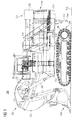
- hydraulic mining shovel 100 comprises a superstructure (upper carriage) 102, an undercarriage 104, and an attachment 106 with an implement 108.
- a slewing gear device (swing gear device) 110 is mounted to superstructure 102 and undercarriage 104 to enable a relative rotary movement to occur between superstructure 102 and undercarriage 104.
- Superstructure 102 includes a plurality of modules mounted to one another and/or to a main frame 112 extending longitudinally in a bottom region of superstructure 102 (in Fig. 1 a front end of main frame 112 is visible only).
- the modules include a power module 114, a counterweight module 116 with a counterweight 117, an operator cab module 118, a first exhaust aftertreatment module 120, and a second exhaust aftertreatment module and an oil cooler module (see Figs. 2 and 3 as both are not visible in the side view of Fig. 1 ). Said modules are described in more detail herein under reference to Figs. 2 to 5 .
- a movable service unit 115 is provided in a bottom region of power module 114.
- Said service unit 115 may selectively move in direction to ground surface 122 for providing access to refill inlets and/or control panels for an operator on ground level.
- service unit 115 may be retracted into an accommodation chamber in power module 114, for example by means of a hydraulic actuator.
- the retraction-and-extension-mechanism for service unit 115 may be configured to pivot service unit 115 out of its accommodation chamber.
- Attachment 106 includes work implement 108 such as a face shovel, which is movably mounted to a front end of a stick 126 that is in turn movably mounted to a boom 128.
- work implement 108 such as a face shovel
- a plurality of hydraulic actuators 130 allow moving work implement 108, stick 126 and boom 128 as desired during mining operation.
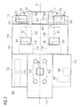
- Fig. 2 for describing an exemplary layout concept of superstructure modules and their components. It is noted that in Figs. 2 and 3 , modules and components are indicated in a schematic manner only. Furthermore, components accommodated inside a respective module are indicated by dashed lines, whereas solid lines indicate a visibility of the component in a top view onto superstructure 102 assuming that possibly existing covers are demounted.
- superstructure 102 includes main frame 112, power module 114, counterweight module 116, operator cab module 118, first and second aftertreatment modules 120, 121, and oil cooler module 132.
- main frame 112 extends along a central longitudinal axis A and supports modules 114, 116, 118 and 132.
- main frame 112 is shown in part only as it is partly overlapped, in particular, by power module 114 and counterweight module 116.
- main frame 112 further supports swing drives 134 and a rotary distributor 136 for rotating slewing gear device 110 (see Fig. 1 ).
- first and second internal combustion engines 138 and 140 are accommodated such that their longitudinal axes (crankshaft axes) B1, B2 extend parallel to central longitudinal axis A of main frame 112. Additionally, for providing hydraulic power to various components of hydraulic mining shovel 100, first and second pump transfer gearboxes 142 and 144 are operationally connected to respective outputs of first and second internal combustion engines 138 and 140 via respective couplings 146, 148.
- engines 138 and 140 are configured as diesel engines.
- a space-saving arrangement may include that first and second internal combustion engines 138, 140 are configured and arranged mirror-symmetrically on opposing sides of power module 114 with respect to central longitudinal axis A. In other embodiments, for example, first and second internal combustion engines 138, 140 may be configured and arranged merely substantially mirror-symmetrically on opposing sides of power module 114 with respect to central longitudinal axis A.
- Intake air is provided to internal combustion engines 138, 140 by first and second air intake units 147 and 149 which are mounted on a top deck 150 of power module 114. Said air intake units 147, 149 are fluidly connected to engines 138, 140 via suitable piping not shown in detail. Additionally, air intake units 147 and 149 may be equipped with air filters for cleaning ambient air before supplying the same to engines 138, 140.
- counterweight module 116 includes counterweight 117 (see Fig. 1 ).
- Counterweight module 116 is mounted onto main frame 112 with a clearance to power module 114 for allowing relative movement between modules 116 and 114 such that counterweight module 116 is decoupled (isolated) against vibrations of power module 114, in particular, of first and second internal combustion engines 138, 140.
- first and second engine coolers 152 and 154 including fans for drawing ambient air from the environment are accommodated in counterweight module 116 for cooling engines 138 and 140, respectively.
- first and second exhaust aftertreatment modules 120 and 121 are mounted on a top deck 164 of counterweight module 116.
- Each exhaust aftertreatment module 120, 121 includes a respective reductant tank and pump unit 160, 162 and a respective selective catalytic reduction (SCR) unit 156, 158.
- first and second exhaust aftertreatment modules 120, 121 are configured and arranged mirror-symmetrically at opposing sides of top deck 164 of counterweight module 116 with respect to central longitudinal axis A.
- SCR units 156, 158 are mounted closer to central longitudinal axis A than reductant tank and pump units 160, 162.
- reductant tank and pump units 160, 162 may be mounted closer to central longitudinal axis A than SCR units 156, 158.
- SCR units 156 and 158 are oriented such that their longitudinal axes C1 and C2, respectively, extend parallel to central longitudinal axis A of main frame 112, whereas reductant tank and pump units 160 and 162 are oriented such that their longitudinal axes D1 and D2 extend perpendicular to central longitudinal axis A.
- first and second exhaust aftertreatment modules 120, 121 may be configured and arranged merely substantially mirror-symmetrically at opposing sides of top deck 164 of counterweight module 116 with respect to central longitudinal axis A.
- a substantially mirror-symmetrically arrangement may include installation tolerances, and/or merely relatively small deviations from a corresponding mirror-symmetrical arrangement, for instance, a single digit percentage deviation relative to a corresponding absolute mirror-symmetrical arrangement.
- first and second exhaust aftertreatment modules 120 and 121 are substantially isolated against vibrations of internal combustion engines 138 and 140 due to the installation onto counterweight module 116. Further, first and second exhaust aftertreatment modules 120 and 121 are arranged to prevent occurrence of any collisions with material to be excavated and other vehicles. The reason is that modules 120 and 121 do not or at least not substantially project beyond counterweight module 116 in directions of central longitudinal axis A and perpendicular to central longitudinal axis A. Still further, as can be seen in conjunction with Fig. 1 , modules 120, 121 and railways (see Fig.
- top decks 150 and 164 may function as barriers for increasing safety of operators walking on top decks 150 and 164 to prevent that operators may fall down to working surface 122. Additionally, the mirror-symmetrical arrangement provides a homogeneous mass distribution acting onto counterweight module 116, which further increases the stability of hydraulic mining shovel 100 and may also allow to reduce a mass of counterweight 117 (see Fig. 1 ) as such a mass reduction may be compensated by exhaust aftertreatment modules 120, 121.
- First reductant tank and pump units 160, 162 may be integrated units including a storage chamber for storing a reductant, and at least one pump for pumping the reductant from the storage chamber to the respective SCR units 156 or 158.
- first reductant tank and pump units 160, 162 may be integrated units including a storage chamber for storing a reductant, and at least one pump for pumping the reductant from the storage chamber to the respective SCR units 156 or 158.
- Each storage chamber may have a capacity of several hundred liters, for example more than 500 liters, because the to-be-treated exhaust gas amount generated by engines 138 and 140 may be relatively large.
- the storage capacity may be configured to provide enough reductant for at least one work shift, preferably at least one work day.
- an operator may connect a supply pipe to a reductant refill inlet(s) 166 (see Fig. 1 ), which is/are fluidly connected to storage chambers of tank and pump units 160 and 162.
- Said reductant refill inlet(s) 166 may be provided at movable service unit 115.
- tank and pump units 160 and 162 may be provided with reductant refill inlets.
- Reductant is supplied from first and second tank and pump units 160 and 162 to SCR units 156 and 158, respectively, via fluid connections (not shown).
- Said SCR units 156 and 158 include exhaust passages being fluidly connected to exhaust outlets of internal combustion engines 138 and 140, for example, with flexible piping, because of potential relative movements between power module 114 and counterweight module 116.
- SCR units 156 and 158 inject reductant from tank and pump units 160 and 162 into respective exhaust gas streams provided by engines 138 and 140, and passing the exhaust passages of SCR units 156 and 158.
- the injected reductant together with a suitable catalyzer structure housed in SCR units 156 and 158 ensures that a considerable amount of nitrogen oxides present in the exhaust gas streams is reduced to diatomic nitrogen and water. Then, the cleaned exhaust gas leaves SCR units 156 and 158 to the environment.
- operator cab module 118 may provide an operator seat 168 and a control panel 167 for an operator to control hydraulic mining shovel 100 as desired.
- control panel 167 may include joysticks, levers, buttons, and the like for propelling hydraulic mining shovel, and controlling operation of implement 108, attachment 106, and slewing gear device 110.
- operator cab module 118 may further include interfaces, for example a display, for conveying information such as machine parameters and environmental conditions to an operator.
- a remote control and/or interface unit for the operator may be provided outside of operator cab module 118, for example remote from hydraulic mining shovel 100.
- Oil cooler module 132 is provided on an opposite side of mainframe 112 with respect to operator cab module 118. In oil cooler module 132, at least one oil cooler 170 is accommodated.
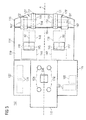
- Fig. 3 shows an arrangement of modules and components of superstructure 102' very similar to the one shown in Fig. 2 except that first and second tank and pump units 160' and 162' are oriented in a different manner.
- first and second tank and pump units 160' and 162' are oriented such that their respective longitudinal axes D1' and D2' are parallel to longitudinal axes A, C1 and C2.
- said arrangement provides the same advantages as the one shown in Fig. 2 , for example in terms of collision avoidance, operator safety, space-saving arrangement and configuration, and homogeneous mass distribution.
- FIGs. 4 and 5 for describing exhaust aftertreatment modules 120 and 121 in more detail. Specifically, in Figs. 4 and 5 , second aftertreatment module 121' is depicted. However, features described in the following may apply to both exhaust aftertreatment modules 120 and 121 if applicable and desired.
- a carrier structure 172 may be provided to support and fasten both reductant pump and tank unit 160' and SCR unit 158. By mounting both units 160' and 158 onto one carrier, namely carrier structure 172, exhaust aftertreatment module 121' can be moved onto counterweight module 116 and installed thereon as a whole in one single step.
- carrier structure 172 may include at least one mounting unit (not shown in further detail) for lifting the same with a crane or the like.
- a common carrier structure may be provided for both exhaust aftertreatment modules 120 and 121.
- the common carrier structure may be formed as an integral unit, or as two separate carrier structures 172 fastened to one another.
- first and second exhaust aftertreatment modules may be lifted and/or installed on hydraulic mining shovel 100 as a whole in one single step.
- carrier structure 172 may further include fastening units for realeasably securing exhaust aftertreatment module 121' onto counterweight module 116 (see Figs. 1 to 3 ).
- the fastening means may include bolts, screws or the like.
- a drip pan 174 is disposed below reductant tank and pump unit 162' such that in the event of a leakage, the leaking highly-corrosive reductant can be collected in drip pan 174 instead of flowing into power module 114 and/or counterweight module 116 (see Figs. 1 to 3 ), which may damage components accommodated therein, for example internal combustion engines 138, 140 and engine coolers 152 and 154.
- drip pan 174 may be integrated into carrier structure 172.
- a volume of drip pan 174 may be not sufficient to collect the entire leaking reductant.
- a drainage mechanism may be included which ensures that in case drip pan 174 is almost entirely filled, the reductant is drained from the drip pan in a desired manner to ensure that the leaking reductant does not come into contact with any endangered component.
- a drainage mechanism may include relatively low-height side walls 176 of drip pan 174 in a region which would allow reductant to overflow in a direction away from power module 114.
- a heat insulation wall 178 may be arranged between reductant tank and pump unit 162' and SCR unit 158 to reduce a heat transfer from SCR unit 158 to reductant tank and pump unit 162'.
- Said heat insulation wall 178 allows to arrange reductant tank and pump unit 162' and SCR unit 158 close together although the reductant in the storage chamber of reductant tank and pump unit 162' is very sensitive to heat.
- heat insulation wall 178 may include a heat insulating material.
- heat insulation wall 178 may be releasably mounted to carrier structure 172 such that the same can be removed in case of very low temperatures, for example during winter, to allow a certain heat transfer which (slightly) warms the reductant, because the same may be also very sensitive to cold.
- module 121' may further include a protection cover 180 covering reductant tank and pump unit 162' and SCR unit 158.
- Protection cover 180 may include lifting mounts 182 for moving and installing the same.
- protection cover 180 may cover reductant tank and pump unit 162' or SCR unit 158 only.
- carrier structure 172 and its features is not limited to mirror-symmetrical arrangement and configurations of exhaust aftertreatment modules 120, 121 as shown in Figs. 2 and 3 , but may be used in other arrangements and configurations including, for example, other installation positions of the carrier structure on the hydraulic mining shovel, and more or less exhaust aftertreatment modules and internal combustion engines.
- the hydraulic mining shovel configuration disclosed herein is particularly applicable in hydraulic mining shovels requiring an exhaust aftertreatment device including an SCR unit.
- exhaust aftertreatment units 120, 121 are substantially isolated against vibrations of internal combustion engines 138, 140 due to their arrangement onto counterweight module 116.
- the relatively small overall dimensions of exhaust aftertreatment modules 120, 121 in combination with the non-projecting (or at least not substantially projecting) arrangement onto counterweight module 116 helps to avoid any collisions with material walls and vehicles.
- the modular construction allows retrofitting exhaust aftertreatment modules 120, 121, and eases and quickens installation of the same as all components of exhaust aftertreatment modules 120, 121 can be assembled and connected with one another before actually installing modules 120, 121 on hydraulic mining shovel 100.
- mirror-symmetrical arrangement and configuration is meant to be understood in a generic manner. Specifically, the term refers to a situation in which the parts and units, which are essentially necessary for operation of the respective component or module, are mirrored. Hence, it is intended that features having no key functionality with respect to the desired function of the module do not necessarily have to be mirrored.
- a substantially mirror-symmetric arrangement and configuration with respect to exhaust aftertreatment modules 120 and 121 specifically means that both modules include substantially equal-constructed reductant tank and pump units 160, 162 and substantially equal-constructed SCR units 156, 158 in a substantially mirrored arrangement with respect to a reference axis.
Landscapes
- Engineering & Computer Science (AREA)
- General Engineering & Computer Science (AREA)
- Civil Engineering (AREA)
- Structural Engineering (AREA)
- Mining & Mineral Resources (AREA)
- Chemical & Material Sciences (AREA)
- Mechanical Engineering (AREA)
- Combustion & Propulsion (AREA)
- Chemical Kinetics & Catalysis (AREA)
- Health & Medical Sciences (AREA)
- Toxicology (AREA)
- Exhaust Gas After Treatment (AREA)
- Component Parts Of Construction Machinery (AREA)
Priority Applications (3)
| Application Number | Priority Date | Filing Date | Title |
|---|---|---|---|
| EP15166177.4A EP3091128A1 (fr) | 2015-05-04 | 2015-05-04 | Pelle excavatrice hydraulique avec unité src |
| AU2016202605A AU2016202605A1 (en) | 2015-05-04 | 2016-04-22 | Hydraulic mining shovel with scr unit |
| US15/145,566 US20160326718A1 (en) | 2015-05-04 | 2016-05-03 | Hydraulic mining shovel with scr unit |
Applications Claiming Priority (1)
| Application Number | Priority Date | Filing Date | Title |
|---|---|---|---|
| EP15166177.4A EP3091128A1 (fr) | 2015-05-04 | 2015-05-04 | Pelle excavatrice hydraulique avec unité src |
Publications (1)
| Publication Number | Publication Date |
|---|---|
| EP3091128A1 true EP3091128A1 (fr) | 2016-11-09 |
Family
ID=53039335
Family Applications (1)
| Application Number | Title | Priority Date | Filing Date |
|---|---|---|---|
| EP15166177.4A Withdrawn EP3091128A1 (fr) | 2015-05-04 | 2015-05-04 | Pelle excavatrice hydraulique avec unité src |
Country Status (3)
| Country | Link |
|---|---|
| US (1) | US20160326718A1 (fr) |
| EP (1) | EP3091128A1 (fr) |
| AU (1) | AU2016202605A1 (fr) |
Cited By (2)
| Publication number | Priority date | Publication date | Assignee | Title |
|---|---|---|---|---|
| JP2017166162A (ja) * | 2016-03-15 | 2017-09-21 | 日立建機株式会社 | 建設機械 |
| EP3524736A1 (fr) * | 2018-02-09 | 2019-08-14 | Wirtgen GmbH | Machine de traitement du sol pourvue d'un panneau d'accès pour l'entretien avec zone de stockage et siege |
Families Citing this family (2)
| Publication number | Priority date | Publication date | Assignee | Title |
|---|---|---|---|---|
| JP7273619B2 (ja) * | 2018-06-01 | 2023-05-15 | マニタウォック クレイン カンパニーズ, エルエルシー | クレーン下部走行体上のエンジン排気後処理システムのための取り付け配設 |
| JP7654919B2 (ja) * | 2021-03-31 | 2025-04-02 | 住友建機株式会社 | ショベル、及びショベルの製造方法 |
Citations (8)
| Publication number | Priority date | Publication date | Assignee | Title |
|---|---|---|---|---|
| US20120055149A1 (en) * | 2010-09-02 | 2012-03-08 | Bucyrus International, Inc. | Semi-closed hydraulic systems |
| EP2474672A1 (fr) * | 2009-09-02 | 2012-07-11 | Hitachi Construction Machinery Co., Ltd. | Véhicule de travail de type à roues |
| JP2013181400A (ja) * | 2012-02-29 | 2013-09-12 | Komatsu Ltd | 作業機械 |
| US20130259626A1 (en) * | 2012-04-03 | 2013-10-03 | Harnischfeger Technologies, Inc. | Counterweight system for an industrial machine |
| US20130292386A1 (en) * | 2012-05-01 | 2013-11-07 | Aaron S. Klauer | Diesel exhaust fluid and fuel fill system |
| US20140219763A1 (en) * | 2013-02-01 | 2014-08-07 | Caterpillar Global Mining Llc | Power shovel hoist machinery and ballast configuration |
| US20150000256A1 (en) * | 2012-07-05 | 2015-01-01 | Komatsu Ltd. | Engine unit and work vehicle |
| NL2011673C2 (en) * | 2013-10-25 | 2015-04-29 | Ihc Holland Ie Bv | Drive system for a trailing dredger. |
Family Cites Families (1)
| Publication number | Priority date | Publication date | Assignee | Title |
|---|---|---|---|---|
| US9222420B2 (en) * | 2012-08-02 | 2015-12-29 | Ford Global Technologies, Llc | NOx control during cylinder deactivation |
-
2015
- 2015-05-04 EP EP15166177.4A patent/EP3091128A1/fr not_active Withdrawn
-
2016
- 2016-04-22 AU AU2016202605A patent/AU2016202605A1/en not_active Abandoned
- 2016-05-03 US US15/145,566 patent/US20160326718A1/en not_active Abandoned
Patent Citations (8)
| Publication number | Priority date | Publication date | Assignee | Title |
|---|---|---|---|---|
| EP2474672A1 (fr) * | 2009-09-02 | 2012-07-11 | Hitachi Construction Machinery Co., Ltd. | Véhicule de travail de type à roues |
| US20120055149A1 (en) * | 2010-09-02 | 2012-03-08 | Bucyrus International, Inc. | Semi-closed hydraulic systems |
| JP2013181400A (ja) * | 2012-02-29 | 2013-09-12 | Komatsu Ltd | 作業機械 |
| US20130259626A1 (en) * | 2012-04-03 | 2013-10-03 | Harnischfeger Technologies, Inc. | Counterweight system for an industrial machine |
| US20130292386A1 (en) * | 2012-05-01 | 2013-11-07 | Aaron S. Klauer | Diesel exhaust fluid and fuel fill system |
| US20150000256A1 (en) * | 2012-07-05 | 2015-01-01 | Komatsu Ltd. | Engine unit and work vehicle |
| US20140219763A1 (en) * | 2013-02-01 | 2014-08-07 | Caterpillar Global Mining Llc | Power shovel hoist machinery and ballast configuration |
| NL2011673C2 (en) * | 2013-10-25 | 2015-04-29 | Ihc Holland Ie Bv | Drive system for a trailing dredger. |
Cited By (5)
| Publication number | Priority date | Publication date | Assignee | Title |
|---|---|---|---|---|
| JP2017166162A (ja) * | 2016-03-15 | 2017-09-21 | 日立建機株式会社 | 建設機械 |
| EP3524736A1 (fr) * | 2018-02-09 | 2019-08-14 | Wirtgen GmbH | Machine de traitement du sol pourvue d'un panneau d'accès pour l'entretien avec zone de stockage et siege |
| CN110130195A (zh) * | 2018-02-09 | 2019-08-16 | 维特根有限公司 | 具有提供装载空间的维护翻板的地面加工机 |
| US10815626B2 (en) | 2018-02-09 | 2020-10-27 | Wirtgen Gmbh | Earth working machine having a maintenance door offering storage space |
| CN110130195B (zh) * | 2018-02-09 | 2021-10-22 | 维特根有限公司 | 具有提供装载空间的维护翻板的地面加工机 |
Also Published As
| Publication number | Publication date |
|---|---|
| US20160326718A1 (en) | 2016-11-10 |
| AU2016202605A1 (en) | 2016-11-24 |
Similar Documents
| Publication | Publication Date | Title |
|---|---|---|
| KR101453133B1 (ko) | 건설 기계의 NOx 저감 장치의 배치 구조 | |
| US9004217B2 (en) | Electric work vehicle | |
| KR101720599B1 (ko) | 유압 셔블 | |
| US20160326718A1 (en) | Hydraulic mining shovel with scr unit | |
| EP2806125B1 (fr) | Chargeuse à roues | |
| KR102038731B1 (ko) | 엔진 장치 | |
| CN105143630B (zh) | 拖拉机 | |
| CN100402762C (zh) | 小型摇摆式挖掘机 | |
| KR101630253B1 (ko) | 작업 차량 | |
| KR20140036180A (ko) | 건설 기계 | |
| JP2012219624A (ja) | 建設機械 | |
| KR101834979B1 (ko) | 건설 기계 | |
| JP2010248895A (ja) | 掘削機 | |
| US10060094B2 (en) | Arrangement structure for a reducing agent tank for a construction machine | |
| KR20200035988A (ko) | 건설기계 | |
| EP3121400B1 (fr) | Système d'alimentation en urée aqueuse pour machine de construction | |
| CN104929738B (zh) | 工程机械 | |
| JP5468393B2 (ja) | 建設機械 | |
| EP2687635A1 (fr) | Structure d'attachement de réservoir d'huile hydraulique de machine de construction | |
| CN105986589B (zh) | 小回转型挖土机 | |
| JP4172135B2 (ja) | 建設機械のフィルタ類装着構造 | |
| KR20240145881A (ko) | 작업 기계 | |
| JP2016188557A (ja) | 作業機 | |
| JP2012207552A (ja) | 建設機械 | |
| JP2020147925A (ja) | 建設機械 |
Legal Events
| Date | Code | Title | Description |
|---|---|---|---|
| PUAI | Public reference made under article 153(3) epc to a published international application that has entered the european phase |
Free format text: ORIGINAL CODE: 0009012 |
|
| AK | Designated contracting states |
Kind code of ref document: A1 Designated state(s): AL AT BE BG CH CY CZ DE DK EE ES FI FR GB GR HR HU IE IS IT LI LT LU LV MC MK MT NL NO PL PT RO RS SE SI SK SM TR |
|
| AX | Request for extension of the european patent |
Extension state: BA ME |
|
| STAA | Information on the status of an ep patent application or granted ep patent |
Free format text: STATUS: THE APPLICATION IS DEEMED TO BE WITHDRAWN |
|
| 18D | Application deemed to be withdrawn |
Effective date: 20170510 |