EP3091132A1 - Structure modulaire préfabriqué - Google Patents
Structure modulaire préfabriqué Download PDFInfo
- Publication number
- EP3091132A1 EP3091132A1 EP16168489.9A EP16168489A EP3091132A1 EP 3091132 A1 EP3091132 A1 EP 3091132A1 EP 16168489 A EP16168489 A EP 16168489A EP 3091132 A1 EP3091132 A1 EP 3091132A1
- Authority
- EP
- European Patent Office
- Prior art keywords
- elements
- vertical
- horizontal
- main
- modular
- Prior art date
- Legal status (The legal status is an assumption and is not a legal conclusion. Google has not performed a legal analysis and makes no representation as to the accuracy of the status listed.)
- Withdrawn
Links
- 230000003014 reinforcing effect Effects 0.000 claims abstract description 11
- 238000004519 manufacturing process Methods 0.000 claims abstract description 9
- 239000004793 Polystyrene Substances 0.000 claims description 2
- 230000037431 insertion Effects 0.000 claims description 2
- 238000003780 insertion Methods 0.000 claims description 2
- 239000011810 insulating material Substances 0.000 claims description 2
- 230000002093 peripheral effect Effects 0.000 claims description 2
- 229920002223 polystyrene Polymers 0.000 claims description 2
- 230000001105 regulatory effect Effects 0.000 claims description 2
- 239000000463 material Substances 0.000 description 4
- 230000032258 transport Effects 0.000 description 3
- 238000011010 flushing procedure Methods 0.000 description 2
- 238000010276 construction Methods 0.000 description 1
- 238000009434 installation Methods 0.000 description 1
Images




Classifications
-
- E—FIXED CONSTRUCTIONS
- E04—BUILDING
- E04B—GENERAL BUILDING CONSTRUCTIONS; WALLS, e.g. PARTITIONS; ROOFS; FLOORS; CEILINGS; INSULATION OR OTHER PROTECTION OF BUILDINGS
- E04B1/00—Constructions in general; Structures which are not restricted either to walls, e.g. partitions, or floors or ceilings or roofs
- E04B1/343—Structures characterised by movable, separable, or collapsible parts, e.g. for transport
- E04B1/34315—Structures characterised by movable, separable, or collapsible parts, e.g. for transport characterised by separable parts
-
- E—FIXED CONSTRUCTIONS
- E04—BUILDING
- E04H—BUILDINGS OR LIKE STRUCTURES FOR PARTICULAR PURPOSES; SWIMMING OR SPLASH BATHS OR POOLS; MASTS; FENCING; TENTS OR CANOPIES, IN GENERAL
- E04H3/00—Buildings or groups of buildings for public or similar purposes; Institutions, e.g. infirmaries or prisons
- E04H3/08—Hospitals, infirmaries, or the like; Schools; Prisons
-
- E—FIXED CONSTRUCTIONS
- E04—BUILDING
- E04B—GENERAL BUILDING CONSTRUCTIONS; WALLS, e.g. PARTITIONS; ROOFS; FLOORS; CEILINGS; INSULATION OR OTHER PROTECTION OF BUILDINGS
- E04B1/00—Constructions in general; Structures which are not restricted either to walls, e.g. partitions, or floors or ceilings or roofs
- E04B2001/0053—Buildings characterised by their shape or layout grid
- E04B2001/0076—Buildings with specific right-angled horizontal layout grid
Definitions
- the invention refers to a prefabricated modular structure for manufacturing buildings of various kind during emergency situations, like schools, hospitals, temporary assistance centres, and similar inhabited structures, with different and variable configurations, and with reduced times for assembling and installing and for disassembling the various component parts of the same structure.
- This prefabricated modular structure is realized with component elements with standard dimensions such that all the component elements may be transported without problems onto transport means of any kind, like wagons, trucks, containers and the like, the structure being also adapted to be assembled and disassembled into different places and positions.
- the present invention refers to a prefabricated modular structure, adapted to be used for manufacturing buildings of various kind during emergency situations, like schools, hospitals, temporary assistance centres, and similar inhabited structures, with different and variable configurations as desired, and with reduced times for assembling and installing and disassembling the various components elements of the same structure.
- This prefabricated modular structure is realized with the component elements that will be described, having standard dimensions such to allow to transport without problems all the component elements onto transports means of any kind, like wagons, trucks, containers and the like, the structure being also adapted to be assembled and disassembled into different places and positions.
- the modular component elements used for realizing the prefabricated structure are the following:
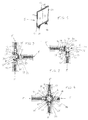
- the main modular element 5 is substantially constituted by a vertical closed flat frame 12 with rectangular shape, forming a wall with the upper and lower horizontal sides that are shorter, and parallel to each other, and with the vertical sides that are parallel to each other.
- the width of such main element is selected smaller than the internal free width of a standard container ISO of 20 ft, in such a way that the main modular element 5 may be housed also into the containers and transported with these latter, whereas the height of the same main element may theoretically be such as to reach the internal free depth of each container (of about 6 meters), but this height is advantageously selected with a smaller size (of about 2,560 meters), in such a way that each container may contain two pallets placed side by side and supporting various main modular elements, and that the internal free height of each assembled module be many times greater than 2,400 meters, that constitutes a correct height for the operation and that complies with the building law relating to the stationary buildings structures of traditional type.
- Each wall frame 12 is realized with peripheral metallic walls, that may be full or may also define to each other an internal free space into which there are inserted some insulating panels made of insulating material of traditional type (e.g. polystyrene), that in the example are constituted by two panels 13 and 14 of the male and female type with standard thickness and width (in the present example of 50 mm and 1 meter, respectively).
- insulating panels made of insulating material of traditional type (e.g. polystyrene), that in the example are constituted by two panels 13 and 14 of the male and female type with standard thickness and width (in the present example of 50 mm and 1 meter, respectively).
- Each flat frame 12 may also be made hollow into its interior, and without insulating panels, and in such case it provides a reinforcing structure that will be described, or it may provide also through openings through the relative insulating panels 13 and 14, with the shape of doors and windows (not shown in the Figure), and the insulating panels may include also windows and door frames of any type.
- Each frame 12 furthermore, has the upper 15 and lower 16 horizontal sides with the same profile, slightly hollowed for the entire length of the relative side, that in the upper side 15 performs the function of gutter for collecting and draining of rainwater, and in the lower side 16 serves for supporting the floor of the modular structure.
- the lower side 16 there are also fixed at least two support feet 17 and 18, identical and opportunely shaped for being able to be arranged directly onto the ground or onto suitable support platforms (not shown) applied onto the ground, such support feet being arranged closed to the correspondent vertical side of the frame, as visible in Fig.
- the two vertical sides 19 and 20 of any type of frame acting like stanchions, have the same hollowed profile for a determined depth for all the height of the relative side and have reduced thickness with respect to the upper and lower horizontal sides 15, 16 and perform, in addition to the load bearing function, also the function of gutter descending element, for draining the rainwater on to the ground, as well as of interconnecting element among the frames.
- each vertical stanchion that is constituted by a metallic section bar 21 that, in the illustrated example, is shaped with a square cross-section provided with an internal circular hole 22 for the passage of the rainwater and its conveying downward, and into its side turned inward the main modular element 5 the section bar 21 is lengthened with two short projections 23 and 24, that are parallel and spaced away to each other for housing and securing the correspondent end portion of the relative insulating panel, whereas into the side opposite to the above-mentioned side the section bar 21 is shaped with two additional short projections (not shown), that are parallel and close to each other and are provided for the connection of the same section bar with each first connecting modular element 6, and these additional projections are bored in positions correspondent to each other, for allowing the passage of correspondent bolts 25 for fixing the relative connecting element 6.
- each vertical stanchion may be shaped also with conformations different from that described, provided that it always performs the same function, thus without departing from the protection sphere of the
- the first connecting element 6, named also column, is substantially constituted by a first curved element 26 and by a second curved element 27 both having a relative curved portion 28 and 29 that are parallel and spaced away to each other, of which the first curved element 26 has a radius of curvature greater than that one of the second curved element 27, and both said curved elements are extended in the vertical direction for the entire height of each stanchion.
- the first curved element 26 and the second curved element 27 are lengthened with relative short horizontal rectilinear end portions (not indicated), entering for a determined depth into the hollow (not shown) of the adjacent vertical side of the relative main element 5, and both the end portions of each first and second curved element 26, 27 are bored in positions coinciding with the positions of the relative through holes of the additional projections of the section bar 21 of a relative vertical stanchion.
- first and second curved elements 26 and 27 there is also provided integral a short flat flange 30, orthogonal to the same end portions and adapted to be arranged into external contact to the vertical side of a main element 5, for all the width of the same side, whereas near the other one of the horizontal end portions of such first and second curved elements 26 and 27 there is provided integral an additional short flat flange 31, orthogonal to the same end portions and identical to the previous flange, and adapted to be arranged into external contact to the vertical side of another main element 5, orthogonal to the previous main element 5, and for the entire width of the same side.
- the two flat flanges 30 and 31 are secured onto the relative first curved element 26 and second curved element 27, in a such position that, when these curved elements are secured to the relative vertical stanchions 21 (see Fig. 2 ) of the two main elements 5 arranged orthogonal to each other as visible from this Figure, the correspondent curved portion 28 and 29 of these curved elements be extended for the entire distance existing between the two flat flanges 30 and 31, in a manner do not leave free spaces between the same flanges.
- the junction between the two main elements 5 arranged orthogonal to each other, as shown in Fig. 2 is effected by levelling at first the horizontal lower sides of such main elements 5 with respect to the ground, by regulating the height of the support feet 17 and 18, as already described previously, and then by introducing a fixing bolt 25 into the through holes coinciding to each other of both the horizontal end portions of said first and second curved elements 26 and 27 and the additional projections of each vertical section bar 21 of the stanchions, and moreover by introducing some U-shaped bars 32 into the space existing between both the end portions of said first and second curved elements 26 and 27 and the opposite flat side (not indicated) of the same vertical section bar.
- the object of such U-shaped bars 32 is to lock the heads 33 of the fixing bolts 25, adjacent to the same bars, thereby preventing the bolts from being unscrewed from the outside.
- Such second connecting element 7 is provided for joining to each other the section bars adjacent to each other of each main element 5, which section bars are identical and comprise the same connection devices of the ones previously described (that is a fixing bolt 25 and a U-shaped bar 32), the connecting element referred to being substantially constituted by two curved elements 27 identical to the previously described curved element 27, of which a first curved element 27 is provided for joining the section bar 21 of one of the vertical main elements 5 (in this case, of the upper one element in the Fig.
- a second curved element 27 is symmetrical and aligned with respect to the first curved element 27, and is provided for joining the section bar 21 of the horizontal main element 5 with the section bar 21 of the third main element 5 arranged vertical (in this case, of the lower element in the Fig. 3 ).
- first curved element 27 is joined to a short flat flange 34, placed near one end portion of the same curved element and adapted to be arranged into external contact to the vertical side of the vertical and upper main element 5, and such first curved element 27 is also joined to an additional short flat flange 35, placed near the other end portion of the same curved element, and adapted to be arranged into external contact to the vertical side of the horizontal main element 5.
- the second curved element 27 is joined to said additional flat flange 35, situated near an end portion of the same curved element and adapted to be arranged into external contact to the vertical side of the horizontal main element 5, and such second curved element 27 is also joined to an additional short flat flange 36, placed near the other end portion of the same curved element and adapted to be arranged into external contact to the vertical side of the other lower vertical main element 5.
- the second connecting element 7, finally, is constituted by a rectilinear portion 37 that in the example of Fig. 3 is arranged vertical, and which is extended in the vertical direction for the entire height of the stanchions, and this rectilinear portion 37 is joined with the flat flange 34 near an end portion of the same rectilinear portion, and such rectilinear portion 37 is also joined to the additional flat flange 36 near the other end portion of the same rectilinear portion.
- the third connecting modular element 8 for joining to each other four main modular elements 5, of which two elements (that in the Figure are the vertically arranged elements 5) are arranged aligned to and spaced away from each other by the third connecting element 8, and the other two elements (that in the Figure are the horizontally arranged elements 5), are oriented horizontally and orthogonally with respect to the first two vertical elements 5, and are also arranged aligned to and spaced away from each other by the same third connecting element 8, and also in this case a relative insulating panel is mounted onto all said main modular elements 5.
- Such third connecting element 8 is provided for joining to each other the section bars adjacent to each other of each main element 5, which section bars are identical and comprise the same connecting devices of the ones previously described (that is a fixing bolt 25 and a U-shaped bar 32), the connecting element referred to being substantially constituted by two curved elements 27 identical to and placed as the curved elements 27, as well as joined to the same flanges 34, 35 e 36 as described in the Fig. 3 , and such third connecting element 8 being also constituted by two additional curved elements 27 identical to and placed as the just described curved elements 27, however symmetrical and aligned with respect to these latters.
- the first one of the additional curved elements 27 is joined to a short flat flange 38, placed near one end portion of the same curved element and adapted to be arranged into external contact to the vertical side of one of the horizontal main elements 5 (in the example of Fig. 4 , of the left-side horizontal main element 5), and such first additional curved element 27 is also joined to said flat flange 34 near the other end portion of the same curved element.
- the second one of the curved elements 27 is joined to the flat flange 38 situated near an end portion of the same curved element and is also joined to said flat flange 36, situated near the other end portion of the same curved element.
- the fourth connecting modular element 9, constituting the floor of the present structure which is substantially constituted both by first horizontal and rectilinear metallic cross-pieces 39, that are identical to and arranged parallel from each other and in the longitudinal direction of different main modular elements 5 aligned and joined to each other, and by second horizontal and rectilinear metallic cross-pieces 40, that are identical to and smaller than the first cross-pieces 39, and which are arranged parallel to each other and in the transversal direction of different main modular elements 5 aligned and joined to each other, and all the first and second cross-pieces 39 and 40 are joined to each other and with the lower sides 16 of said modular elements 5 aligned and joined from each other, with such an arrangement as to be able to house some horizontal floor plates 41 identical and arranged horizontally aligned to each other, forming the walkable floor.
- Each first longitudinal horizontal cross-piece 39 and each second transversal horizontal cross-piece element 40 has an upper fixed section bar 42 and two movable lower shells 43, of which the upper fixed section bar 42 has a cross-section shaped almost of square shape, and is extended downward with two short and thin vertical side walls 44 and 45, parallel and spaced away to each other, and bored at determined intervals for the whole length of the same section bar, and the movable lower shells 43 are symmetrical to each other and are formed each by a short upper vertical portion 48 and a C-shaped lower portion 49, wherein the C-shaped portion of each shell 43 is bored at determined intervals for its whole length, at positions that are coinciding with those ones of the holes of the side walls 44 and 45 of the section bar 42, for allowing the passage of a correspondent fixing bolt 50, the head of which (not shown) is arranged externally to the shell wall and the stem of which (not shown) is at first inserted into a correspondent hole of the section bar side wall respectively opposite, and then is tight
- Such shells 43 are to support the relative side edge of a horizontal floor plate 41, and in the indicated example there are shown two floor plates 41 aligned and spaced away to each other by the cross-piece 39, the side edges 51 and 52 of which are laid on to a relative shell 43 and supported by the same.
- the fourth connecting modular element 9 comprises also two additional lower movable shells 53 and 54, that are identical to such movable lower shells 43, which additional shells are applied to the short and thin side vertical walls 55 and 56, which are identical to the preceding vertical walls 44 and 45, and are extended downward from the lower side 16 of each main modular element 5, each shell of which is bored for the passage of a fixing bolt 57, that is inserted also through correspondent through holes (not shown) provided at determined intervals for the whole length of such side walls 55 and 56.
- each floor plate 41 with a determinate size in to the relative housing position of a floor support structure obtained as described it is then sufficient at first to loose the fixing bolts which are foreseen, and then to displace each shell in the horizontal direction up to the position suitable to support the correspondent side edge of the floor plate with this size. Finally, on to the shells there is applied the relative floor plate and the shells are then secured in this position by clamping their fixing bolts to the relative side walls of the same plate.
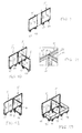
- the visible modular structure is constituted both by two main elements 5 assembled aligned to each other, and into which it is inserted a relative insulating panel 13 and 14, and by an additional modular element 5 internally empty (namely, without insulating panels) that is secured orthogonally on to the front of the above-described main elements 5, and by a longitudinal cross-piece 39 and by two transversal cross-pieces 40, supporting the longitudinal cross-piece 39, and each one which is secured as it will be described to the centre line of the relative main element 5.
- Such a longitudinal cross-piece 39 is supported also onto the ground by means of support feet 59 adjustable in height and identical to the feet 17 and 18 of each main element 5, which are secured along the cross-piece 39 at determined intervals (in the example, there are shown four support feet 59), and the free end portions of the longitudinal cross-piece 39 are bolted, through head plates (not shown), to the centre line respectively of a first and second pair of main elements (not shown), assembled aligned to each other, that are fixed in a position orthogonal to the relative vertical sides 19 and 20 of two above-described main elements 5.
- each transversal cross-piece 40 is not provided with lower support feet, and is supported with a free end portion thereof by a head plate (not shown), that is bolted to the centre line of the lower side 16 of the two relative main elements 5, and with the other free end portion thereof is supported by another head plate (not shown), that is bolted to the centre line of the lower side of two additional main elements (not shown), arranged aligned to each other, which are secured orthogonally to the vertical side 20 of the empty element 5, in a position parallel to the preceding two main elements 5 visible in the Figure.
- the longitudinal cross-piece 39 is supported by the transversal cross-pieces 40 thanks to correspondent hollows (not shown) provided in the central zone of the transversal cross-pieces, into which hollows the longitudinal cross-piece 39 is inserted.
- the two main elements 5 aligned to each other are joined to the other main element 5 orthogonally thereto by means of the second connecting elements 7 described with reference to the Fig. 3 .
- the floor structure realized by assembling to each other the above-described component elements, in the considered example forms a set of squared painted backgrounds (not shown), into which there are inserted relative floor plates 41 (not shown in the Figure), arranged at the same level, which are then locked in position as described with reference to the Fig. 6 . Referring always to the Fig.
- the empty main element 5 is reinforced with a reinforcing structure constituted by the fifth modular element 10, and formed by a vertical bar 60, that is inserted into the empty space of a main element 5 and applied into contact with the relative vertical side 19 of this main element, to which it is opportunely secured.
- a vertical bar is also fixed in the same manner to the other vertical side 20 of this main element 5, that as already described is fixed to two additional main elements arranged parallel to the two main elements 5 visible in this Figure, and this additional vertical bar and the additional main elements are not represented here for simplicity.
- each side edge of each one of the flat roofs 61 it is applied a fixing flange 62, shaped with a short and thin horizontal rectilinear portion 63, adapted to be arranged into contact to the upper surface of the side edge of the roof 61, and such a flange horizontal portion is bent for forming a first short and thin vertical portion 64, adapted to be arranged into contact to the external side surface 65 of the roof side edge, and for forming also a second short and thin vertical portion 66 directed downward, which is arranged parallel to the first vertical portion 64 and is joined to the same and it is extended downward in such a way that, when the flange 62 is applied in position, it may enter slightly the hollow 67 defined in the upper hollowed side 15 of the main element.
- Such a first flange vertical portion 64 is still bent downward for forming a short and thin horizontal portion (not shown) and a short and thin lower vertical portion (also not shown), ending with an end portion bent like a hook 68.
- the fastening in position of each side edge of the flat roof 61 with the relative vertical section bar 21 is then effected by arranging at first the horizontal portion 63 and the first vertical portion 64 of the flange respectively to the upper surface and to the external side surface 65 of the roof side edge, in a manner that the second vertical portion of the flange 66 enters partially the hollow 67 and that the lower horizontal portion of the flange be arranged below the lower surface of the roof side edge and that the lower vertical portion of the flange be spaced away laterally from said hollowed horizontal side 15.
- each roof side edge is laid partially on to the hollowed horizontal side 15 and the fastening and locking in position of the roof is obtained by means of said flange 62 and a sliding bracket 69, formed by a rectilinear vertical portion 70, the upper end portion 71 of which shaped as a hook is adapted to be hooked with the hook 68, and which is also joined to a short horizontal portion 72, adapted to abut in the lower side on to the upper horizontal side 15, and the vertical portion 70 of the bracket 69 is also bored for inserting a bolt 73, onto which a wing head 74 may be screwed and unscrewed.
- bracket 69 is hooked with its hook 71 into the hook 68 of the flange 62 and the horizontal portion of bracket 72 is pushed in abutment in the lower part on to the upper hollowed side 15, thereafter said wing head 74 is screwed onto the bolt 73 up to the bracket 69 is firmly tightened to said flange 62 and the upper hollowed side 15. Then, under the condition, as it is visible in the Fig.
- the vertical portions 66 of the two flanges 62 are spaced away to each other, by defining a vertical passage (not shown) into which rainwater penetrate, that fall into the gutter hollow 67 of the horizontal side 15, from which they are conveyed into the inlet of the relative gutter descending element of each vertical side of the main element 5, and are therefore drained onto the ground.
- Fig. 8 it is shown a modular structure formed by the same component elements of Fig. 5 , comprising the floor plates 41 and the roofs 61 (of which in the Figure only a roof 61 is visible), and these component elements are joined to two additional main elements 5 arranged parallel to the empty main element 5, of which the left side main element has on opening 75 for entering into the same modular structure.
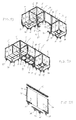
- Figs. 9-18 there are shown the assembling phases performed for assembling the different modular elements of a modular structure realized in the base building configuration, identical to and with the same component elements described in the Figs. 5-8 .
- such a base modular structure of having the dimensions of two base modules has the external dimensions of about 2,400 meters x 4,700 meters and a height of about 2,650 meters. All the component elements of this structure may be inserted into one pallet with a length of 2,852 meters, width of 2,280 meters and height of 1,190 meters, which may be introduced into a standard container ISO of 20 feet, into which therefore there may be introduced four above-mentioned pallets, with an obtainable total volume equal to about four times the transported volume.
- Figs. 19-24 it is shown in which manner the above-described base modular structures may be integrated with some special modules that will be described hereinafter, which are adapted to allow to realize some rooms of a dimension double than that of the base module, namely with ports of about m. 4,500 without columns and/or intermediate vertical structures.
- FIG. 19 there are shown as example two base modular structures that are joined to each other by a special module, which base structures are formed the one by a module with seven main elements 5 and the other one with a module formed by four main elements 5.
- These two base modular structures are spaced away to each other by two additional main elements 5, that may be made of any type (in the example, they are formed by two main elements with an empty internal space), and which are arranged aligned to each other and joined to the above mentioned base modular structures, whereas into the intermediate spans the port of the two base modular structures is covered by the special structure.
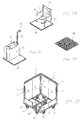
- Figs. 26-31 there are shown some special elements for bathroom, that may be combined with the modular structures according to the present invention.
- a special floor 89 with sink 90 arranged onto a furniture 91 containing both the boiler and the delivering pump and all the other instruments allowing the operation of the sanitary service.
- the sink 90 comprises also the telescopic arm 92 and the showerhead 93.
- the special floor 98 intended to be used as shower tray and relative drainage.
- the base structure of a standard bathroom constituted by base modules formed by main elements 5 with full wall, or main elements with door opening 76, connected to each other by a first connecting modular element 6 and bolted with the U-shaped safety bars 32.
- the floor reinforcing structure is constituted by first great cross-pieces 39 and by second small cross-pieces 40.
- Fig. 30 it is shown the load bearing structure of the Fig. 29 , into which there are inserted the special floor elements and, in particular, the special floor 89 with sink 90, the special floor 98 with shower and the special floor 94 with toilet with seat 95. Only after having connected to each other the delivery sides and the drainages of the above mentioned special floors, it is possible to position also the fourth floor element constituted by a standard floor element 41.
- FIG. 31 is shown the same load bearing structure with the special elements of the Fig. 30 with an overlying standard roof 61 secured in the already described way to the underlying structure.
Landscapes
- Engineering & Computer Science (AREA)
- Architecture (AREA)
- Civil Engineering (AREA)
- Structural Engineering (AREA)
- Health & Medical Sciences (AREA)
- Public Health (AREA)
- Physics & Mathematics (AREA)
- Electromagnetism (AREA)
- Working Measures On Existing Buildindgs (AREA)
- Floor Finish (AREA)
Applications Claiming Priority (1)
| Application Number | Priority Date | Filing Date | Title |
|---|---|---|---|
| ITPN2015A000012A ITPN20150012A1 (it) | 2015-05-05 | 2015-05-05 | Struttura prefabbricata modulare per la costruzione in situazioni di emergenza di edifici di vario genere, come scuole, ospedali, centri di accoglienza temporanea e strutture abitative simili, con configurazioni diverse e variabili, e con ridotti tempi di montaggio e d'installazione, nonche' di smontaggio delle varie parti componenti della struttura stessa |
Publications (1)
| Publication Number | Publication Date |
|---|---|
| EP3091132A1 true EP3091132A1 (fr) | 2016-11-09 |
Family
ID=53765336
Family Applications (1)
| Application Number | Title | Priority Date | Filing Date |
|---|---|---|---|
| EP16168489.9A Withdrawn EP3091132A1 (fr) | 2015-05-05 | 2016-05-05 | Structure modulaire préfabriqué |
Country Status (2)
| Country | Link |
|---|---|
| EP (1) | EP3091132A1 (fr) |
| IT (1) | ITPN20150012A1 (fr) |
Cited By (4)
| Publication number | Priority date | Publication date | Assignee | Title |
|---|---|---|---|---|
| CN108517966A (zh) * | 2018-03-27 | 2018-09-11 | 南京汤泉建设集团有限公司 | 一种全装配可拆卸建筑房屋结构及安装施工工艺 |
| CN113700354A (zh) * | 2021-08-21 | 2021-11-26 | 江苏耀中建设工程有限公司 | 一种装配式手术室 |
| US11773613B2 (en) | 2020-05-05 | 2023-10-03 | The Boldt Group, Inc. | Modular configurable hospital system and method |
| US12252878B2 (en) | 2021-05-05 | 2025-03-18 | The Boldt Group, Inc. | Modular configurable structural unit system |
Citations (8)
| Publication number | Priority date | Publication date | Assignee | Title |
|---|---|---|---|---|
| EP0711585A2 (fr) * | 1994-10-11 | 1996-05-15 | Larry David Hunts | Système de construction et méthode pour connecter entre-eux des panneaux rigides dans des maisons de poupées, maisons jouets, baraques et autres structures |
| WO2006082227A1 (fr) * | 2005-02-04 | 2006-08-10 | Trimed-Pro Srl | Module d’habitation a elements prefabriques extensible dans toutes les directions et toutes les formes |
| WO2008000035A1 (fr) * | 2006-06-29 | 2008-01-03 | Pluscreate Pty Ltd | Bâtiment |
| US20090223161A1 (en) * | 2008-03-06 | 2009-09-10 | Segall Stuart C | Relocatable habitat unit |
| AU2010200477A1 (en) * | 2009-02-23 | 2010-09-09 | Instant Structures Pty Ltd | Wall connection arrangement and method |
| WO2010116012A1 (fr) * | 2009-04-08 | 2010-10-14 | Aria Domus S.L. | Élément structural creux en résine synthétique renforcée pour construction modulaire légère et procédé de construction modulaire correspondant |
| WO2012152096A1 (fr) * | 2011-05-10 | 2012-11-15 | 厦门吉信德宠物用品有限公司 | Ensemble normalisé pour l'assemblage de maison d'animal de compagnie/meuble/chambre mobile |
| US20150033639A1 (en) * | 2011-08-09 | 2015-02-05 | Blue Planet Buildings (Uk) Limited | Modular assembly shelter |
-
2015
- 2015-05-05 IT ITPN2015A000012A patent/ITPN20150012A1/it unknown
-
2016
- 2016-05-05 EP EP16168489.9A patent/EP3091132A1/fr not_active Withdrawn
Patent Citations (8)
| Publication number | Priority date | Publication date | Assignee | Title |
|---|---|---|---|---|
| EP0711585A2 (fr) * | 1994-10-11 | 1996-05-15 | Larry David Hunts | Système de construction et méthode pour connecter entre-eux des panneaux rigides dans des maisons de poupées, maisons jouets, baraques et autres structures |
| WO2006082227A1 (fr) * | 2005-02-04 | 2006-08-10 | Trimed-Pro Srl | Module d’habitation a elements prefabriques extensible dans toutes les directions et toutes les formes |
| WO2008000035A1 (fr) * | 2006-06-29 | 2008-01-03 | Pluscreate Pty Ltd | Bâtiment |
| US20090223161A1 (en) * | 2008-03-06 | 2009-09-10 | Segall Stuart C | Relocatable habitat unit |
| AU2010200477A1 (en) * | 2009-02-23 | 2010-09-09 | Instant Structures Pty Ltd | Wall connection arrangement and method |
| WO2010116012A1 (fr) * | 2009-04-08 | 2010-10-14 | Aria Domus S.L. | Élément structural creux en résine synthétique renforcée pour construction modulaire légère et procédé de construction modulaire correspondant |
| WO2012152096A1 (fr) * | 2011-05-10 | 2012-11-15 | 厦门吉信德宠物用品有限公司 | Ensemble normalisé pour l'assemblage de maison d'animal de compagnie/meuble/chambre mobile |
| US20150033639A1 (en) * | 2011-08-09 | 2015-02-05 | Blue Planet Buildings (Uk) Limited | Modular assembly shelter |
Cited By (4)
| Publication number | Priority date | Publication date | Assignee | Title |
|---|---|---|---|---|
| CN108517966A (zh) * | 2018-03-27 | 2018-09-11 | 南京汤泉建设集团有限公司 | 一种全装配可拆卸建筑房屋结构及安装施工工艺 |
| US11773613B2 (en) | 2020-05-05 | 2023-10-03 | The Boldt Group, Inc. | Modular configurable hospital system and method |
| US12252878B2 (en) | 2021-05-05 | 2025-03-18 | The Boldt Group, Inc. | Modular configurable structural unit system |
| CN113700354A (zh) * | 2021-08-21 | 2021-11-26 | 江苏耀中建设工程有限公司 | 一种装配式手术室 |
Also Published As
| Publication number | Publication date |
|---|---|
| ITPN20150012A1 (it) | 2016-11-05 |
Similar Documents
| Publication | Publication Date | Title |
|---|---|---|
| US8875445B2 (en) | Light weight modular units for staggered stacked building system | |
| EP4121609A1 (fr) | Système pour construction modulaire architecturale | |
| US9062448B2 (en) | Pivotally erectable structural frame system | |
| KR20190124218A (ko) | 모듈식 빌딩 커넥터 | |
| US20090223153A1 (en) | Modular building capable of being readily assembled | |
| AU2019232888B2 (en) | A void platform and a method for providing a platform support across a building void | |
| CA3088705A1 (fr) | Abri construit a partir de panneaux d'interconnexion | |
| US8341902B2 (en) | Multi-story buildings from prefabricated concrete components | |
| EP3091132A1 (fr) | Structure modulaire préfabriqué | |
| CN104114784A (zh) | 用于海运集装箱建筑物结构的高度可调节的支柱 | |
| WO2014000019A1 (fr) | Système de construction | |
| CN114599842A (zh) | 多功能连接器 | |
| AU2021221627A1 (en) | Building components, a building structure formed therefrom and a method of construction thereof | |
| US3940903A (en) | Prefabricated transportable room element for use in the construction of a plural storey building | |
| RU2397295C2 (ru) | Каркас для здания | |
| US11988005B2 (en) | Crypt system | |
| KR101279139B1 (ko) | 숙소용 모듈러 유닛의 복도부 연결장치 | |
| WO2014056024A1 (fr) | Ensemble d'unités de bâtiment | |
| GB2611036A (en) | Framework construction strut | |
| KR20050049015A (ko) | 조립식 건축모듈 및 이를 이용한 시공방법 | |
| KR101385554B1 (ko) | 하프 슬라브를 이용한 조립식 건축구조물 | |
| JP7369165B2 (ja) | 居住用ユニット | |
| WO2018146202A1 (fr) | Bâtiment modulaire pouvant être réutilisé et son procédé de montage | |
| WO2017058117A1 (fr) | Système de connecteur de construction modulaire et procédé de connexion d'unités de construction modulaires | |
| JP2023026817A (ja) | 連結方法 |
Legal Events
| Date | Code | Title | Description |
|---|---|---|---|
| PUAI | Public reference made under article 153(3) epc to a published international application that has entered the european phase |
Free format text: ORIGINAL CODE: 0009012 |
|
| AK | Designated contracting states |
Kind code of ref document: A1 Designated state(s): AL AT BE BG CH CY CZ DE DK EE ES FI FR GB GR HR HU IE IS IT LI LT LU LV MC MK MT NL NO PL PT RO RS SE SI SK SM TR |
|
| AX | Request for extension of the european patent |
Extension state: BA ME |
|
| 17P | Request for examination filed |
Effective date: 20170503 |
|
| GRAP | Despatch of communication of intention to grant a patent |
Free format text: ORIGINAL CODE: EPIDOSNIGR1 |
|
| INTG | Intention to grant announced |
Effective date: 20170710 |
|
| STAA | Information on the status of an ep patent application or granted ep patent |
Free format text: STATUS: THE APPLICATION IS DEEMED TO BE WITHDRAWN |
|
| 18D | Application deemed to be withdrawn |
Effective date: 20171121 |