EP3091273A1 - Structure optique pour voyant lumineux - Google Patents
Structure optique pour voyant lumineux Download PDFInfo
- Publication number
- EP3091273A1 EP3091273A1 EP15166297.0A EP15166297A EP3091273A1 EP 3091273 A1 EP3091273 A1 EP 3091273A1 EP 15166297 A EP15166297 A EP 15166297A EP 3091273 A1 EP3091273 A1 EP 3091273A1
- Authority
- EP
- European Patent Office
- Prior art keywords
- optical structure
- exit beam
- exit
- structural element
- scattered
- Prior art date
- Legal status (The legal status is an assumption and is not a legal conclusion. Google has not performed a legal analysis and makes no representation as to the accuracy of the status listed.)
- Granted
Links
Images




Classifications
-
- F—MECHANICAL ENGINEERING; LIGHTING; HEATING; WEAPONS; BLASTING
- F21—LIGHTING
- F21S—NON-PORTABLE LIGHTING DEVICES; SYSTEMS THEREOF; VEHICLE LIGHTING DEVICES SPECIALLY ADAPTED FOR VEHICLE EXTERIORS
- F21S41/00—Illuminating devices specially adapted for vehicle exteriors, e.g. headlamps
- F21S41/20—Illuminating devices specially adapted for vehicle exteriors, e.g. headlamps characterised by refractors, transparent cover plates, light guides or filters
- F21S41/25—Projection lenses
- F21S41/255—Lenses with a front view of circular or truncated circular outline
-
- F—MECHANICAL ENGINEERING; LIGHTING; HEATING; WEAPONS; BLASTING
- F21—LIGHTING
- F21S—NON-PORTABLE LIGHTING DEVICES; SYSTEMS THEREOF; VEHICLE LIGHTING DEVICES SPECIALLY ADAPTED FOR VEHICLE EXTERIORS
- F21S41/00—Illuminating devices specially adapted for vehicle exteriors, e.g. headlamps
- F21S41/20—Illuminating devices specially adapted for vehicle exteriors, e.g. headlamps characterised by refractors, transparent cover plates, light guides or filters
-
- F—MECHANICAL ENGINEERING; LIGHTING; HEATING; WEAPONS; BLASTING
- F21—LIGHTING
- F21S—NON-PORTABLE LIGHTING DEVICES; SYSTEMS THEREOF; VEHICLE LIGHTING DEVICES SPECIALLY ADAPTED FOR VEHICLE EXTERIORS
- F21S41/00—Illuminating devices specially adapted for vehicle exteriors, e.g. headlamps
- F21S41/20—Illuminating devices specially adapted for vehicle exteriors, e.g. headlamps characterised by refractors, transparent cover plates, light guides or filters
- F21S41/25—Projection lenses
-
- F—MECHANICAL ENGINEERING; LIGHTING; HEATING; WEAPONS; BLASTING
- F21—LIGHTING
- F21S—NON-PORTABLE LIGHTING DEVICES; SYSTEMS THEREOF; VEHICLE LIGHTING DEVICES SPECIALLY ADAPTED FOR VEHICLE EXTERIORS
- F21S41/00—Illuminating devices specially adapted for vehicle exteriors, e.g. headlamps
- F21S41/20—Illuminating devices specially adapted for vehicle exteriors, e.g. headlamps characterised by refractors, transparent cover plates, light guides or filters
- F21S41/25—Projection lenses
- F21S41/265—Composite lenses; Lenses with a patch-like shape
-
- F—MECHANICAL ENGINEERING; LIGHTING; HEATING; WEAPONS; BLASTING
- F21—LIGHTING
- F21S—NON-PORTABLE LIGHTING DEVICES; SYSTEMS THEREOF; VEHICLE LIGHTING DEVICES SPECIALLY ADAPTED FOR VEHICLE EXTERIORS
- F21S41/00—Illuminating devices specially adapted for vehicle exteriors, e.g. headlamps
- F21S41/20—Illuminating devices specially adapted for vehicle exteriors, e.g. headlamps characterised by refractors, transparent cover plates, light guides or filters
- F21S41/25—Projection lenses
- F21S41/275—Lens surfaces, e.g. coatings or surface structures
-
- F—MECHANICAL ENGINEERING; LIGHTING; HEATING; WEAPONS; BLASTING
- F21—LIGHTING
- F21S—NON-PORTABLE LIGHTING DEVICES; SYSTEMS THEREOF; VEHICLE LIGHTING DEVICES SPECIALLY ADAPTED FOR VEHICLE EXTERIORS
- F21S41/00—Illuminating devices specially adapted for vehicle exteriors, e.g. headlamps
- F21S41/20—Illuminating devices specially adapted for vehicle exteriors, e.g. headlamps characterised by refractors, transparent cover plates, light guides or filters
- F21S41/285—Refractors, transparent cover plates, light guides or filters not provided in groups F21S41/24 - F21S41/2805
-
- F—MECHANICAL ENGINEERING; LIGHTING; HEATING; WEAPONS; BLASTING
- F21—LIGHTING
- F21S—NON-PORTABLE LIGHTING DEVICES; SYSTEMS THEREOF; VEHICLE LIGHTING DEVICES SPECIALLY ADAPTED FOR VEHICLE EXTERIORS
- F21S41/00—Illuminating devices specially adapted for vehicle exteriors, e.g. headlamps
- F21S41/20—Illuminating devices specially adapted for vehicle exteriors, e.g. headlamps characterised by refractors, transparent cover plates, light guides or filters
- F21S41/29—Attachment thereof
- F21S41/295—Attachment thereof specially adapted to projection lenses
-
- F—MECHANICAL ENGINEERING; LIGHTING; HEATING; WEAPONS; BLASTING
- F21—LIGHTING
- F21S—NON-PORTABLE LIGHTING DEVICES; SYSTEMS THEREOF; VEHICLE LIGHTING DEVICES SPECIALLY ADAPTED FOR VEHICLE EXTERIORS
- F21S41/00—Illuminating devices specially adapted for vehicle exteriors, e.g. headlamps
- F21S41/30—Illuminating devices specially adapted for vehicle exteriors, e.g. headlamps characterised by reflectors
- F21S41/32—Optical layout thereof
-
- F—MECHANICAL ENGINEERING; LIGHTING; HEATING; WEAPONS; BLASTING
- F21—LIGHTING
- F21V—FUNCTIONAL FEATURES OR DETAILS OF LIGHTING DEVICES OR SYSTEMS THEREOF; STRUCTURAL COMBINATIONS OF LIGHTING DEVICES WITH OTHER ARTICLES, NOT OTHERWISE PROVIDED FOR
- F21V5/00—Refractors for light sources
-
- G—PHYSICS
- G02—OPTICS
- G02B—OPTICAL ELEMENTS, SYSTEMS OR APPARATUS
- G02B5/00—Optical elements other than lenses
- G02B5/02—Diffusing elements; Afocal elements
- G02B5/0205—Diffusing elements; Afocal elements characterised by the diffusing properties
- G02B5/021—Diffusing elements; Afocal elements characterised by the diffusing properties the diffusion taking place at the element's surface, e.g. by means of surface roughening or microprismatic structures
-
- F—MECHANICAL ENGINEERING; LIGHTING; HEATING; WEAPONS; BLASTING
- F21—LIGHTING
- F21W—INDEXING SCHEME ASSOCIATED WITH SUBCLASSES F21K, F21L, F21S and F21V, RELATING TO USES OR APPLICATIONS OF LIGHTING DEVICES OR SYSTEMS
- F21W2102/00—Exterior vehicle lighting devices for illuminating purposes
-
- F—MECHANICAL ENGINEERING; LIGHTING; HEATING; WEAPONS; BLASTING
- F21—LIGHTING
- F21W—INDEXING SCHEME ASSOCIATED WITH SUBCLASSES F21K, F21L, F21S and F21V, RELATING TO USES OR APPLICATIONS OF LIGHTING DEVICES OR SYSTEMS
- F21W2102/00—Exterior vehicle lighting devices for illuminating purposes
- F21W2102/10—Arrangement or contour of the emitted light
- F21W2102/13—Arrangement or contour of the emitted light for high-beam region or low-beam region
- F21W2102/135—Arrangement or contour of the emitted light for high-beam region or low-beam region the light having cut-off lines, i.e. clear borderlines between emitted regions and dark regions
- F21W2102/16—Arrangement or contour of the emitted light for high-beam region or low-beam region the light having cut-off lines, i.e. clear borderlines between emitted regions and dark regions having blurred cut-off lines
-
- F—MECHANICAL ENGINEERING; LIGHTING; HEATING; WEAPONS; BLASTING
- F21—LIGHTING
- F21W—INDEXING SCHEME ASSOCIATED WITH SUBCLASSES F21K, F21L, F21S and F21V, RELATING TO USES OR APPLICATIONS OF LIGHTING DEVICES OR SYSTEMS
- F21W2102/00—Exterior vehicle lighting devices for illuminating purposes
- F21W2102/10—Arrangement or contour of the emitted light
- F21W2102/17—Arrangement or contour of the emitted light for regions other than high beam or low beam
- F21W2102/18—Arrangement or contour of the emitted light for regions other than high beam or low beam for overhead signs
Definitions
- the invention relates to an optical structure for a lighting device of a motor vehicle headlight, which lighting device is arranged to emit light to form a first unmodified light distribution in a region in front of the lighting device, wherein the optical structure of the lighting device is assigned or part of the lighting device is such that the optical Structure of at least a portion of the total luminous flux of the illumination device is irradiated, wherein the - generated by the illumination device, unmodified light distribution - modified from the optical structure to a predetermined, modified second light distribution, wherein the optical structure of two, three or more optical structure elements consists, each structural element has a light-scattering effect.
- the invention relates to a lighting device for a vehicle headlight with such an optical structure.
- the invention relates to a vehicle headlight with at least one such lighting device.
- the bright-dark line (HD line) - ie outside the primary illuminated area - minimum and maximum light intensities are required in certain regions. These act as a "signlight” and allow the alignment of overhead direction signs when illuminated by passing vehicles.
- the luminous intensities used are usually above the usual scattered light values but far below the luminous intensities below the HD line. The required light values must be achieved with the lowest possible glare effect.
- Signal is usually realized by special facets in the projection lens (size at least a few millimeters) or by discrete, small elevations. adversely this is especially true that these structures are perceived from the outside as bright points of light and are thus increasingly rejected, especially for design reasons. In addition, such devices are tuned to the underlying optical system-changes are made to the desired function is no longer guaranteed.
- the quantification of this HD transition is made by the maximum of a gradient along a vertical section through the light-dark boundary.
- the logarithm of the illuminance is calculated at measuring points in 0.1 ° intervals and their difference is formed, whereby the gradient function is obtained.
- the maximum of this function is called the gradient of the HD boundary. Since this definition imitates the perception of human brightness only in an inaccurate manner, differently perceived HD lines can have the same measured gradient value or different gradients can be measured for similar-looking HD lines.
- Gradientaufweichung is usually done by changing the lens surface. a lens of a lighting device.
- various solutions are in use: For example, a softer HD limit can be achieved by random roughening of the lens surface, however, this leads to dazzling oncoming road users.
- modulation e.g., superposition of two sine waves, small pits in the form of sphere sections, etc.
- Such solutions are highly dependent on the luminous flux distribution through the lens, changes in this regard, for example by varying the lighting technology, then have a strong and sometimes negative impact on the generated luminous flux distribution.
- a first subset of the structural elements is formed so that on this first subset of the structural elements incident, generated by the illumination device beams pass through the first subset of the structural elements, each beam from the respective structural element to a first exit beam, to a second exit beam and to at least one further exit beam is broken.
- the above-mentioned light image generated by a lighting device is formed as a superposition of scattering patterns of individual structural elements.
- the scattering pattern of a single structural element is generated by the light passing through the structural element.
- Different areas in the scattering pattern are illuminated when at least two of the exit beams do not overlap in the spread pattern.
- a second subset of the structural elements is formed such that the incident on this second subset of the structural elements light is scattered in the form of exactly one beam.
- the second subset of the structural elements is empty and the optical structure consists only of the structural elements of the first subset.
- the size of the second subset may, for example, depend on how much light has to be scattered in the form of the above-mentioned further exit beam.
- the production of the optical structure can be more easily automated if the structural elements have a hexagonal, preferably a regular hexagonal base surface, ie the base surfaces of the structural elements completely cover a hexagonal, preferably a regular hexagonal lattice and cover the surfaces between the hexagonal lattices Corner points of the grid are covered by the base of exactly one structural element.
- the hexagonal grid is formed as a regular hexagonal grid, which has regular hexagonal grid one, two or more parallel rows, which rows parallel to one by a diagonal extend over two sides of one of the surfaces defined direction, wherein formed as a regular hexagons bases of the first subset of the structural elements cover every other row.
- the first subset of the structural elements has at least one rising area, one pouring area and one, two or more rising flanks, and wherein the rising area is the one arriving at the respective structural element from the lighting device generated radiation beam to the first exit beam, the outlet region of the incident on the respective structural element, the radiation beam generated by the illumination device to the second exit beam, and the one, two or more rising flanks incident on the respective structural element, generated by the illumination device beam to at least one break further exit beam.
- the rise region has a substantially linear course and / or the outlet region has an essentially S-shaped, preferably cos-like, course.
- the structural elements are in each case symmetrical, in particular mirror-symmetrical, with respect to a axis extending parallel to the diagonal over two sides through a geometric center point of the structural element.
- the at least one rising flank is formed in a section through the structural element along a plane parallel to the base plane substantially V-shaped.
- the at least one rising edge in a section through the structural element along a plane parallel to the base plane in relation to a through the geometric center of the structural element parallel to the diagonal over two sides extending axis symmetrical, in particular mirror-symmetrical is formed and has a corner and an opening angle.
- an optical structure according to the invention is advantageous for an illumination device, which illumination device is adapted to image the light emitted by it in the form of a dimmed light distribution, in particular a low beam distribution, wherein the dimmed light distribution, in particular the low beam distribution has an HD boundary
- the optical structure, in particular the structural elements is / are designed such that a portion of the luminous flux of the illumination device is imaged in an area above the HD boundary.
- an initially described signlight can be generated in an optimum manner, for example by deflecting a small proportion of the luminous flux passing through the structural element into a corresponding region of each optical structural element. It is expedient to consider the deflection angles of individual exit beams on a scattering image, on which scattering image an orthogonal coordinate system with a horizontal (h-axis) and a vertical (v-axis) is defined.
- the structural elements have a rise area, an exit area and exactly one rising flank, wherein the part of the radiation beam incident on the rise area of the structural element is refracted into a first exit ray bundle, which first exit ray bundles are below the h-axis is scattered, the incident on the outlet region of the structural element part of the beam is refracted into a second exit beam, which second exit beam is scattered above the h-axis, which is incident on the flank of the structural element part of the radiation beam to a third exit beam, which third Outgoing beam is scattered above the h-axis.
- the second exit beam is scattered in a range between 0 ° and 3 ° above the h-axis.
- the edge has a rise in a range between 5 ° and 20 ° or an increase of about 13.8 ° or 18.9 ° and the third exit beam in a Range between 2 ° and 4 ° or between 4 ° and 5 ° or between 5 ° and 7 ° above the h-axis is scattered.
- the structural elements have a rise area, an outlet area and exactly three rising flanks, wherein the part of the radiation beam incident on the rise area of the structural element is refracted into a first exit ray bundle, which first exit ray bundles are below the h-axis is scattered, the incident on the outlet region of the structural element part of the beam is refracted into a second exit beam, which second exit beam is scattered above the h-axis, the incident on the flanks of the structural element part of the beam to a third, a fourth and a Fifth exit beam is refracted, wherein the exit beam are scattered in a region above the h-axis and the fourth exit beam neither the third exit beam nor the fifth exit str A bundle of rays overlaps in the scattering pattern. It is expedient if the second exit beam is scattered in a range between 0 ° and 3 ° above the h-axis.
- first and the third flank have an increase in a range between 8 ° and 12 ° or an increase of approximately 10 ° and the second flank an increase in a range between 12 ° and 16 ° or an increase of about 14 ° and the third and the fifth exit beams are scattered in a range between 4 ° and 6 ° above the h-axis and the fourth exit beam is scattered in a range between 6 ° and 8 ° above the h-axis.
- the structural elements have a rise area, an outlet area and an edge, wherein the flank is V-shaped and has a corner point and an opening angle, wherein the corner point lies in the geometric center of their base area, which on the rise area of Structural element incident part of the beam is refracted into a first exit beam, which first exit beam is scattered below the h-axis, which is refracted on the outlet region of the structural element part of the radiation beam to a second exit beam, which second exit beam is scattered above the h-axis in that the part of the beam incident on the V-shaped flank of the structural element is in each case refracted into a third and a fourth exit beam, the exit beams being scattered in a region above the h-axis d and the third exit beam and the fourth exit beam do not overlap in the spread image.
- the V-shaped edge has an increase in a range between 8 ° and 20 ° or an increase of about 18.9 ° and the third exit beam in a range between 3 ° and 7 ° vertically and is scattered horizontally between -12 ° and -7 ° and the fourth exit beam is scattered in a range between 3 ° and 7 ° vertically and between + 7 ° and + 12 ° horizontally.
- the dimension of a structural element for example a circumferential diameter and / or the maximum distance to the base area, is greater, in particular very much larger than the wavelength of visible light.
- the maximum distance from the base surface in the micrometer range is provided.
- the maximum distance to the base area in the range of 5-10 microns or in the range of 10 - 13 microns or in the range of 13 - 17 microns or about 9.3 microns or about 10.6 Micrometer or about 12.15 microns or about 16.6 microns.
- the circumference diameter or a length of the structural elements is in the millimeter range.
- the diameter or a length of the structural elements between 0.5 - 2 millimeters or is about 1 millimeter.
- the optical structure is arranged on at least one, preferably exactly one boundary surface of an optical element, which is designed in the form of a scattering or a cover plate of the illumination device.
- the optical structure is arranged on at least one surface of an optical element in the form of a lens, in particular a projection lens of the illumination device.
- the optical structure is arranged on the light exit side of the lens.
- the unmodified light beam produces a light distribution contribution with a particular shape, ie certain areas are illuminated on the road or on a screen, other areas are unlit.
- the first exit beam modifies the first unmodified light distribution to the second modified light distribution, whereby the second modified light distribution has a lower gradient of the HD boundary.
- the further exit beam bundles may be expedient for the further exit beam bundles to modify the first unmodified light distribution to the second modified light distribution and to form a "signlight" partial light distribution.
- the invention also relates to a lighting device with at least one, preferably exactly one of the optical structures described above.
- the lighting device is a projection system.
- the illumination device comprises at least one light source, at least one reflector and at least one lens, in particular a projection lens.
- the at least one optical structure is arranged on the lens and / or is formed as an additional optical element.
- the lighting device is a reflection system.
- the lighting device comprises at least one free-form reflector and at least one light source and at least one scatter and / or at least one cover.
- the at least one optical structure is arranged on the at least one scattering and / or the at least one cover plate and / or is formed as an additional optical element.
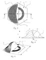
- Fig. 1 shows a side view of a structural element 5 with a rise area 17, a discharge area 18 and a flank 19a.
- An incident light beam 6 emitted by an illumination, not shown here, passes through the structural element and is differently refracted upon exiting, depending on whether the penetrating portion of the radiation beam 6 emerges at the rise region 17, at the outlet region 18 or at the flank 19a. In this case, a total of three different non-overlapping radiation beams 7, 8, 9a are formed.
- the resulting spreading pattern is in Fig. 2 which shows a scattering pattern of the structural element 5 with the flank 19a.
- the beam 7 contributes to the softening of the gradient (area GA in FIG Fig. 2 ) of the modified second Light distribution, wherein by the beam 9a, the above-described Signlight is realized (area SL in Fig. 2 ).
- the structural element 5 of Fig. 1 is from different perspectives in Fig. 3 - Fig. 5 shown. That's how it shows Fig. 3
- the structural element 5 is mirror-symmetrical with respect to the line AA running through a geometric center 24 of the structural element 5 and parallel to a diagonal over two sides 15 of the hexagonal base 10 ,
- a side section along the line AA in Fig. 3 of the structural element 5 is in Fig. 4
- the rise area 17 is linear and the outlet area 18 is substantially S-shaped, preferably similar to a cos-function.
- Fig. 5 shows a perspective view of the structural element Fig. 3 ,
- FIGS. 6-13 relate to two further embodiments of the structural element 5 and the associated spreading images ( Fig. 9 and Fig. 13 ).
- Fig. 6 shows a plan view of a structural element 5 with three rising flanks 19a, 19b, 19c with a hexagonal base 10. Thereby five different radiation beams are formed when passing through an incident beam. The rising angles of the flanks 19a and 19c are equal and different from the rising angle of the flank 19b. This has the result that the beam emerging at the flank 19a, the emerging at the edge 19c beam 19c superimposed in the scattering image, resulting from the in Fig. 9 in which the light contribution to the signlight area SL comprises two segments instead of three.
- Fig. 7 shows a side section BB of the structural element Fig. 6 , wherein the different angles of rise of the flanks are illustrated.
- Fig. 8 shows a perspective view of the structural element Fig. 6 ,
- Fig. 10 shows a plan view of a structural element with a rising V-shaped flank 19a with a hexagonal base 10.
- the V-shaped flank 19a includes an opening angle 22 and is formed such that its vertex 21 in the geometric center 21 of the structural element 5, the geometric center of the hexagonal base 10 is similar, lies.
- the light contribution to the Signlight area SL in Fig. 13 consists essentially of two inclined to the h-axis elongated segments.
- the light contribution to the gradient softening GA is greater in this embodiment of the structural element.
- Fig. 11 shows a side section CC of the structural element Fig. 10.
- Fig. 12 shows a perspective view of the structural element Fig. 10 ,
- All embodiments of the structural elements have characteristic sizes, e.g. the maximum distance 23 of the structural element 5 to the base surface 10 and the circumference diameter 25. These sizes are each in the micro or millimeter range and compared to the typical wavelengths of the light emitted by the illumination device are large enough so that no interference effects occur.
- the grid 13 in Fig. 14 is a regular hexagonal grid, although deviations from the regularity of the grid are quite conceivable.
- the base surfaces 10 of the structural elements 5, 5 ' completely cover the surfaces 11 between the corner points 12 of the grille 13, each surface 11 being covered by the base surface 10 of exactly one structural element 5, 5'.
- the grid can be divided into a plurality of parallel rows 14. Such a row 14 consists of several adjacent surfaces 11 and extends in a direction 16 defined by a diagonal over two sides 15 of a surface 11th
- Fig. 15 shows an embodiment of an optical structure in which the bases 10 of the structural elements 5 cover every other row 14 'of the hexagonal grid 13 and the bases of the remaining structural elements 5' cover the remaining areas of the hexagonal grid 13.
- Fig. 16 schematically shows a lighting device 2 in the form of a projection system, comprising a reflector 30, a light source 29, an (optional) diaphragm assembly 32 and a projection lens 27, with a curved outside 28 and a plane inside.
- Fig. 17 schematically shows a lighting device 2 in the form of a reflection system, comprising a reflector 30, a light source 29 and a lens or cover 26th
- Fig. 18 shows a schematic representation of the projection system FIG. 16 wherein an optical structure 1 according to the invention is arranged on the outside 28 of a lens 27. This optical structure 1 preferably occupies the entire outer side 28 of the lens 29.
- Fig. 19 shows a schematic representation of the reflection module FIG. 17 with an optical structure 1 according to the invention on the outside of the cover or diffuser 26, wherein preferably the optical structure occupies the entire outside of the disk 26.
- Fig. 20 again shows a schematic representation of a projection module, as in FIG. 16 illustrated with an optical structure 1 according to the invention on an additional optical element 31 such as a disc, wherein the optical element 31 between the diaphragm 32 and the lens 28 is arranged.
- Fig. 21 finally shows a schematic representation of a reflection module FIG. 17 with an optical structure 1 according to the invention on an additional optical element 31 such as a disk, which is arranged between the light source 29 and the scattering or cover plate 26.
- a lighting device can also have a plurality of light sources, for example LEDs as light sources, and the light-shaping body can be in the form of one or more light guides, reflectors, etc be formed.
- the optical structure 1 is assigned to the illumination device 2 or is part of the illumination device 2 such that the optical structure 1 is irradiated by at least part of the total luminous flux of the illumination device 2, preferably by the entire optically relevant luminous flux.
- the optical structure is arranged and / or formed such that it is homogeneously illuminated.
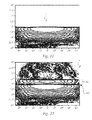
- FIGS. 22 and 23 the first unmodified light distribution 3 and the second modified light distribution 4.
- the first unmodified light distribution is in Fig. 22 is shown as a low-beam distribution 3 with a linear HD boundary.
- the second modified light distribution 4 in Fig. 23 is a modification of the first light distribution 3 and comprises two additional areas resulting from the application of the optical structure according to the invention: the area of the gradient softening GA and the signlight area SL.
- FIG. 23 It can be seen that the area SL above an HD boundary is illuminated with a certain illuminance to produce a signlight. In this case, a portion of the luminous flux of the lighting device 2 in this area SL, ie above the HD boundary, shown. In this way, with the optical structure 1 according to the invention, an initially described Signlight can be generated in an optimum manner.
- the HD limit has a lower gradient than the HD limit of the unmodified light distribution, as is schematically indicated by the greater distance of the Isolux lines in the region of the cut-off line.
- the HD limit of the second modified light distribution 4 is thus "softer".
Landscapes
- Engineering & Computer Science (AREA)
- General Engineering & Computer Science (AREA)
- Physics & Mathematics (AREA)
- General Physics & Mathematics (AREA)
- Optics & Photonics (AREA)
- Non-Portable Lighting Devices Or Systems Thereof (AREA)
Priority Applications (4)
| Application Number | Priority Date | Filing Date | Title |
|---|---|---|---|
| EP15166297.0A EP3091273B1 (fr) | 2015-05-04 | 2015-05-04 | Structure optique pour voyant lumineux |
| US15/143,841 US9879837B2 (en) | 2015-05-04 | 2016-05-02 | Optical structure for signal light |
| CN201610637896.3A CN106195866B (zh) | 2015-05-04 | 2016-05-04 | 用于标志光的光学结构 |
| JP2016093252A JP6266691B2 (ja) | 2015-05-04 | 2016-05-06 | サインライトのための光学構造体 |
Applications Claiming Priority (1)
| Application Number | Priority Date | Filing Date | Title |
|---|---|---|---|
| EP15166297.0A EP3091273B1 (fr) | 2015-05-04 | 2015-05-04 | Structure optique pour voyant lumineux |
Publications (2)
| Publication Number | Publication Date |
|---|---|
| EP3091273A1 true EP3091273A1 (fr) | 2016-11-09 |
| EP3091273B1 EP3091273B1 (fr) | 2020-11-11 |
Family
ID=53059000
Family Applications (1)
| Application Number | Title | Priority Date | Filing Date |
|---|---|---|---|
| EP15166297.0A Active EP3091273B1 (fr) | 2015-05-04 | 2015-05-04 | Structure optique pour voyant lumineux |
Country Status (4)
| Country | Link |
|---|---|
| US (1) | US9879837B2 (fr) |
| EP (1) | EP3091273B1 (fr) |
| JP (1) | JP6266691B2 (fr) |
| CN (1) | CN106195866B (fr) |
Cited By (3)
| Publication number | Priority date | Publication date | Assignee | Title |
|---|---|---|---|---|
| WO2023198442A1 (fr) * | 2022-04-14 | 2023-10-19 | HELLA GmbH & Co. KGaA | Dispositif d'éclairage pour véhicules et procédé de fabrication |
| DE102022109270A1 (de) | 2022-04-14 | 2023-10-19 | Marelli Automotive Lighting Reutlingen (Germany) GmbH | Projektionslichtmodul für einen Kraftfahrzeugscheinwerfer mit einer Overheadelemente aufweisenden Projektionslinse |
| WO2024061674A1 (fr) * | 2022-09-20 | 2024-03-28 | HELLA GmbH & Co. KGaA | Phare pour véhicule à moteur |
Families Citing this family (4)
| Publication number | Priority date | Publication date | Assignee | Title |
|---|---|---|---|---|
| CN106322275A (zh) * | 2016-09-29 | 2017-01-11 | 马瑞利汽车零部件(芜湖)有限公司 | 一种提高近光明暗截止线上方亮度的结构 |
| FR3077363B1 (fr) * | 2018-01-30 | 2021-08-20 | Valeo Vision | Dispositif lumineux a surface generatrice de caustique controlee formant un motif sur une surface cible |
| FR3099543B1 (fr) * | 2019-07-31 | 2024-10-18 | Valeo Vision | Dispositif lumineux indicateur de changement de direction a surface generatrice de caustique controlee formant un motif sur une surface cible |
| EP3974709A1 (fr) * | 2020-09-25 | 2022-03-30 | ZKW Group GmbH | Dispositif d'éclairage pour un phare de véhicule automobile |
Citations (7)
| Publication number | Priority date | Publication date | Assignee | Title |
|---|---|---|---|---|
| DE102008023551A1 (de) * | 2008-05-14 | 2009-11-19 | Automotive Lighting Reutlingen Gmbh | Optische Linse für Beleuchtungszwecke und Beleuchtungseinrichtung mit einer solchen Linse |
| DE102009020593A1 (de) * | 2009-05-09 | 2010-11-11 | Automotive Lighting Reutlingen Gmbh | Zur Erzeugung einer definierten Overhead-Beleuchtung eingerichteter Fahrzeugscheinwerfer |
| EP2587125A2 (fr) * | 2011-10-27 | 2013-05-01 | Automotive Lighting Reutlingen GmbH | Module de projection de phare pour un véhicule automobile |
| DE102012107426A1 (de) * | 2012-08-14 | 2014-02-20 | Hella Kgaa Hueck & Co. | Scheinwerfer für Fahrzeuge |
| US20140334177A1 (en) * | 2012-01-12 | 2014-11-13 | Valeo Vision | Lens for an optical module of a motor vehicle |
| WO2015031924A1 (fr) * | 2013-09-03 | 2015-03-12 | Zizala Lichtsysteme Gmbh | Structure optique pour un dispositif d'éclairage pour un phare de véhicule automobile |
| WO2015031925A1 (fr) * | 2013-09-03 | 2015-03-12 | Zizala Lichtsysteme Gmbh | Structure optique comprenant une microstructure à fonction de dispersion quadratique |
Family Cites Families (9)
| Publication number | Priority date | Publication date | Assignee | Title |
|---|---|---|---|---|
| JP3341325B2 (ja) * | 1992-06-19 | 2002-11-05 | 株式会社デンソー | 車両用灯具装置 |
| JP4008359B2 (ja) * | 2003-01-16 | 2007-11-14 | 株式会社小糸製作所 | 車両用前照灯 |
| JP4597890B2 (ja) * | 2006-03-29 | 2010-12-15 | 株式会社小糸製作所 | 車両用前照灯の灯具ユニット |
| DE102010023177A1 (de) * | 2010-06-09 | 2011-12-15 | Automotive Lighting Reutlingen Gmbh | Lichtmodul für eine Beleuchtungseinrichtung eines Kraftfahrzeugs |
| DE102011003814A1 (de) * | 2011-02-08 | 2012-08-09 | Automotive Lighting Reutlingen Gmbh | Lichtmodul eines Kraftfahrzeugscheinwerfers |
| FR2984456B1 (fr) * | 2011-12-19 | 2015-08-21 | Valeo Vision | Systeme d'eclairage pour projecteur notamment de vehicule automobile |
| JP5982986B2 (ja) | 2012-04-20 | 2016-08-31 | 市光工業株式会社 | 車両用前照灯 |
| JP6232225B2 (ja) * | 2013-08-09 | 2017-11-15 | 株式会社小糸製作所 | 車両用灯具 |
| JP6517556B2 (ja) * | 2015-03-24 | 2019-05-22 | スタンレー電気株式会社 | 車両用灯具 |
-
2015
- 2015-05-04 EP EP15166297.0A patent/EP3091273B1/fr active Active
-
2016
- 2016-05-02 US US15/143,841 patent/US9879837B2/en active Active
- 2016-05-04 CN CN201610637896.3A patent/CN106195866B/zh active Active
- 2016-05-06 JP JP2016093252A patent/JP6266691B2/ja not_active Expired - Fee Related
Patent Citations (7)
| Publication number | Priority date | Publication date | Assignee | Title |
|---|---|---|---|---|
| DE102008023551A1 (de) * | 2008-05-14 | 2009-11-19 | Automotive Lighting Reutlingen Gmbh | Optische Linse für Beleuchtungszwecke und Beleuchtungseinrichtung mit einer solchen Linse |
| DE102009020593A1 (de) * | 2009-05-09 | 2010-11-11 | Automotive Lighting Reutlingen Gmbh | Zur Erzeugung einer definierten Overhead-Beleuchtung eingerichteter Fahrzeugscheinwerfer |
| EP2587125A2 (fr) * | 2011-10-27 | 2013-05-01 | Automotive Lighting Reutlingen GmbH | Module de projection de phare pour un véhicule automobile |
| US20140334177A1 (en) * | 2012-01-12 | 2014-11-13 | Valeo Vision | Lens for an optical module of a motor vehicle |
| DE102012107426A1 (de) * | 2012-08-14 | 2014-02-20 | Hella Kgaa Hueck & Co. | Scheinwerfer für Fahrzeuge |
| WO2015031924A1 (fr) * | 2013-09-03 | 2015-03-12 | Zizala Lichtsysteme Gmbh | Structure optique pour un dispositif d'éclairage pour un phare de véhicule automobile |
| WO2015031925A1 (fr) * | 2013-09-03 | 2015-03-12 | Zizala Lichtsysteme Gmbh | Structure optique comprenant une microstructure à fonction de dispersion quadratique |
Cited By (4)
| Publication number | Priority date | Publication date | Assignee | Title |
|---|---|---|---|---|
| WO2023198442A1 (fr) * | 2022-04-14 | 2023-10-19 | HELLA GmbH & Co. KGaA | Dispositif d'éclairage pour véhicules et procédé de fabrication |
| DE102022109270A1 (de) | 2022-04-14 | 2023-10-19 | Marelli Automotive Lighting Reutlingen (Germany) GmbH | Projektionslichtmodul für einen Kraftfahrzeugscheinwerfer mit einer Overheadelemente aufweisenden Projektionslinse |
| US12560300B2 (en) | 2022-04-14 | 2026-02-24 | HELLA GmbH & Co. KGaA | Lighting device for vehicles and production method |
| WO2024061674A1 (fr) * | 2022-09-20 | 2024-03-28 | HELLA GmbH & Co. KGaA | Phare pour véhicule à moteur |
Also Published As
| Publication number | Publication date |
|---|---|
| US9879837B2 (en) | 2018-01-30 |
| US20160327230A1 (en) | 2016-11-10 |
| JP2016213191A (ja) | 2016-12-15 |
| JP6266691B2 (ja) | 2018-01-24 |
| CN106195866B (zh) | 2019-07-16 |
| CN106195866A (zh) | 2016-12-07 |
| EP3091273B1 (fr) | 2020-11-11 |
Similar Documents
| Publication | Publication Date | Title |
|---|---|---|
| EP3042119B1 (fr) | Structure optique comprenant une microstructure à fonction de dispersion quadratique | |
| EP3042118B1 (fr) | Dispositif d'éclairage d'un phare de véhicule automobile avec une structure optique | |
| EP3091273B1 (fr) | Structure optique pour voyant lumineux | |
| DE102008023551B4 (de) | Beleuchtungseinrichtung in Form eines Projektionsscheinwerfers für Kraftfahrzeuge | |
| AT512468B1 (de) | Beleuchtungsmodul für ein kraftfahrzeug | |
| DE102012202290B4 (de) | Lichtmodul für ein blendungsfreies Kraftfahrzeug-Fernlicht | |
| EP2420728B1 (fr) | Phare avec gradient d'intensité lumineuse ciblée amortie sur la limite de clair-obscur | |
| AT516965B1 (de) | Beleuchtungsvorrichtung für Fahrzeugscheinwerfer | |
| DE102012208566A1 (de) | Beleuchtungsvorrichtung für ein Kraftfahrzeug | |
| DE102011114636A1 (de) | Anordnung und Dimensionierung von Overhead-Elementen auf einer Projektionslinse eines Kraftfahrzeugscheinwerfers | |
| EP2534413A1 (fr) | Module d'éclairage pour l'éclairage de voies de circulation et appareil d'éclairage de voies de circulation | |
| DE102010027322A1 (de) | Mikrooptik für angenähert transversalisotrope Aufweitung einer Scheinwerferlichtverteilung | |
| DE102013215897B4 (de) | Verfahren zum Berechnen der Oberflächen von optischen Linsen | |
| EP3671304B1 (fr) | Procédé de construction d'un élément optique pour un phare de véhicule automobile | |
| WO2018177757A1 (fr) | Lentille de projecteur pour phare de véhicule à moteur | |
| DE102015219211A1 (de) | Lichtmodul für eine Kfz-Beleuchtungseinrichtung | |
| EP4202289B1 (fr) | Système optique pour un phare de véhicule automobile | |
| EP3239593B1 (fr) | Dispositif d'eclairage de vehicule automobile | |
| DE102015222363B4 (de) | Lampenvorrichtung für fahrzeuge | |
| DE202016103287U1 (de) | Scheinwerfer für Schienenfahrzeuge | |
| DE4129955C2 (de) | Kraftfahrzeug-Beleuchtungseinrichtung mit Lichtleiterlementen | |
| EP2734777B1 (fr) | Dispositif d'émission de lumière | |
| DE19853811A1 (de) | Signalleuchte mit kontrollierter Beleuchtungsstärke des Leuchtfelds und Verfahren zur Herstellung eines Kolbens für eine derartige Leuchte | |
| EP4001742A1 (fr) | Phares de véhicule | |
| DE102024111923A1 (de) | Kraftfahrzeugleuchte |
Legal Events
| Date | Code | Title | Description |
|---|---|---|---|
| PUAI | Public reference made under article 153(3) epc to a published international application that has entered the european phase |
Free format text: ORIGINAL CODE: 0009012 |
|
| AK | Designated contracting states |
Kind code of ref document: A1 Designated state(s): AL AT BE BG CH CY CZ DE DK EE ES FI FR GB GR HR HU IE IS IT LI LT LU LV MC MK MT NL NO PL PT RO RS SE SI SK SM TR |
|
| AX | Request for extension of the european patent |
Extension state: BA ME |
|
| STAA | Information on the status of an ep patent application or granted ep patent |
Free format text: STATUS: REQUEST FOR EXAMINATION WAS MADE |
|
| 17P | Request for examination filed |
Effective date: 20170509 |
|
| RBV | Designated contracting states (corrected) |
Designated state(s): AL AT BE BG CH CY CZ DE DK EE ES FI FR GB GR HR HU IE IS IT LI LT LU LV MC MK MT NL NO PL PT RO RS SE SI SK SM TR |
|
| REG | Reference to a national code |
Ref country code: DE Ref legal event code: R079 Ref document number: 502015013776 Country of ref document: DE Free format text: PREVIOUS MAIN CLASS: F21S0008100000 Ipc: G02B0005020000 |
|
| RIC1 | Information provided on ipc code assigned before grant |
Ipc: F21W 102/18 20180101ALI20200428BHEP Ipc: G02B 5/02 20060101AFI20200428BHEP Ipc: F21S 41/255 20180101ALI20200428BHEP Ipc: F21S 41/275 20180101ALI20200428BHEP |
|
| GRAP | Despatch of communication of intention to grant a patent |
Free format text: ORIGINAL CODE: EPIDOSNIGR1 |
|
| STAA | Information on the status of an ep patent application or granted ep patent |
Free format text: STATUS: GRANT OF PATENT IS INTENDED |
|
| INTG | Intention to grant announced |
Effective date: 20200609 |
|
| GRAS | Grant fee paid |
Free format text: ORIGINAL CODE: EPIDOSNIGR3 |
|
| GRAA | (expected) grant |
Free format text: ORIGINAL CODE: 0009210 |
|
| STAA | Information on the status of an ep patent application or granted ep patent |
Free format text: STATUS: THE PATENT HAS BEEN GRANTED |
|
| AK | Designated contracting states |
Kind code of ref document: B1 Designated state(s): AL AT BE BG CH CY CZ DE DK EE ES FI FR GB GR HR HU IE IS IT LI LT LU LV MC MK MT NL NO PL PT RO RS SE SI SK SM TR |
|
| REG | Reference to a national code |
Ref country code: GB Ref legal event code: FG4D Free format text: NOT ENGLISH |
|
| REG | Reference to a national code |
Ref country code: CH Ref legal event code: EP |
|
| REG | Reference to a national code |
Ref country code: AT Ref legal event code: REF Ref document number: 1334039 Country of ref document: AT Kind code of ref document: T Effective date: 20201115 |
|
| REG | Reference to a national code |
Ref country code: DE Ref legal event code: R096 Ref document number: 502015013776 Country of ref document: DE |
|
| REG | Reference to a national code |
Ref country code: IE Ref legal event code: FG4D Free format text: LANGUAGE OF EP DOCUMENT: GERMAN |
|
| REG | Reference to a national code |
Ref country code: NL Ref legal event code: MP Effective date: 20201111 |
|
| PG25 | Lapsed in a contracting state [announced via postgrant information from national office to epo] |
Ref country code: FI Free format text: LAPSE BECAUSE OF FAILURE TO SUBMIT A TRANSLATION OF THE DESCRIPTION OR TO PAY THE FEE WITHIN THE PRESCRIBED TIME-LIMIT Effective date: 20201111 Ref country code: RS Free format text: LAPSE BECAUSE OF FAILURE TO SUBMIT A TRANSLATION OF THE DESCRIPTION OR TO PAY THE FEE WITHIN THE PRESCRIBED TIME-LIMIT Effective date: 20201111 Ref country code: NO Free format text: LAPSE BECAUSE OF FAILURE TO SUBMIT A TRANSLATION OF THE DESCRIPTION OR TO PAY THE FEE WITHIN THE PRESCRIBED TIME-LIMIT Effective date: 20210211 Ref country code: PT Free format text: LAPSE BECAUSE OF FAILURE TO SUBMIT A TRANSLATION OF THE DESCRIPTION OR TO PAY THE FEE WITHIN THE PRESCRIBED TIME-LIMIT Effective date: 20210311 Ref country code: GR Free format text: LAPSE BECAUSE OF FAILURE TO SUBMIT A TRANSLATION OF THE DESCRIPTION OR TO PAY THE FEE WITHIN THE PRESCRIBED TIME-LIMIT Effective date: 20210212 |
|
| PG25 | Lapsed in a contracting state [announced via postgrant information from national office to epo] |
Ref country code: IS Free format text: LAPSE BECAUSE OF FAILURE TO SUBMIT A TRANSLATION OF THE DESCRIPTION OR TO PAY THE FEE WITHIN THE PRESCRIBED TIME-LIMIT Effective date: 20210311 Ref country code: LV Free format text: LAPSE BECAUSE OF FAILURE TO SUBMIT A TRANSLATION OF THE DESCRIPTION OR TO PAY THE FEE WITHIN THE PRESCRIBED TIME-LIMIT Effective date: 20201111 Ref country code: PL Free format text: LAPSE BECAUSE OF FAILURE TO SUBMIT A TRANSLATION OF THE DESCRIPTION OR TO PAY THE FEE WITHIN THE PRESCRIBED TIME-LIMIT Effective date: 20201111 Ref country code: SE Free format text: LAPSE BECAUSE OF FAILURE TO SUBMIT A TRANSLATION OF THE DESCRIPTION OR TO PAY THE FEE WITHIN THE PRESCRIBED TIME-LIMIT Effective date: 20201111 Ref country code: BG Free format text: LAPSE BECAUSE OF FAILURE TO SUBMIT A TRANSLATION OF THE DESCRIPTION OR TO PAY THE FEE WITHIN THE PRESCRIBED TIME-LIMIT Effective date: 20210211 |
|
| REG | Reference to a national code |
Ref country code: LT Ref legal event code: MG9D |
|
| PG25 | Lapsed in a contracting state [announced via postgrant information from national office to epo] |
Ref country code: HR Free format text: LAPSE BECAUSE OF FAILURE TO SUBMIT A TRANSLATION OF THE DESCRIPTION OR TO PAY THE FEE WITHIN THE PRESCRIBED TIME-LIMIT Effective date: 20201111 |
|
| PG25 | Lapsed in a contracting state [announced via postgrant information from national office to epo] |
Ref country code: LT Free format text: LAPSE BECAUSE OF FAILURE TO SUBMIT A TRANSLATION OF THE DESCRIPTION OR TO PAY THE FEE WITHIN THE PRESCRIBED TIME-LIMIT Effective date: 20201111 Ref country code: RO Free format text: LAPSE BECAUSE OF FAILURE TO SUBMIT A TRANSLATION OF THE DESCRIPTION OR TO PAY THE FEE WITHIN THE PRESCRIBED TIME-LIMIT Effective date: 20201111 Ref country code: SK Free format text: LAPSE BECAUSE OF FAILURE TO SUBMIT A TRANSLATION OF THE DESCRIPTION OR TO PAY THE FEE WITHIN THE PRESCRIBED TIME-LIMIT Effective date: 20201111 Ref country code: CZ Free format text: LAPSE BECAUSE OF FAILURE TO SUBMIT A TRANSLATION OF THE DESCRIPTION OR TO PAY THE FEE WITHIN THE PRESCRIBED TIME-LIMIT Effective date: 20201111 Ref country code: EE Free format text: LAPSE BECAUSE OF FAILURE TO SUBMIT A TRANSLATION OF THE DESCRIPTION OR TO PAY THE FEE WITHIN THE PRESCRIBED TIME-LIMIT Effective date: 20201111 Ref country code: SM Free format text: LAPSE BECAUSE OF FAILURE TO SUBMIT A TRANSLATION OF THE DESCRIPTION OR TO PAY THE FEE WITHIN THE PRESCRIBED TIME-LIMIT Effective date: 20201111 |
|
| REG | Reference to a national code |
Ref country code: DE Ref legal event code: R097 Ref document number: 502015013776 Country of ref document: DE |
|
| PG25 | Lapsed in a contracting state [announced via postgrant information from national office to epo] |
Ref country code: DK Free format text: LAPSE BECAUSE OF FAILURE TO SUBMIT A TRANSLATION OF THE DESCRIPTION OR TO PAY THE FEE WITHIN THE PRESCRIBED TIME-LIMIT Effective date: 20201111 |
|
| PLBE | No opposition filed within time limit |
Free format text: ORIGINAL CODE: 0009261 |
|
| STAA | Information on the status of an ep patent application or granted ep patent |
Free format text: STATUS: NO OPPOSITION FILED WITHIN TIME LIMIT |
|
| 26N | No opposition filed |
Effective date: 20210812 |
|
| PG25 | Lapsed in a contracting state [announced via postgrant information from national office to epo] |
Ref country code: IT Free format text: LAPSE BECAUSE OF FAILURE TO SUBMIT A TRANSLATION OF THE DESCRIPTION OR TO PAY THE FEE WITHIN THE PRESCRIBED TIME-LIMIT Effective date: 20201111 Ref country code: NL Free format text: LAPSE BECAUSE OF FAILURE TO SUBMIT A TRANSLATION OF THE DESCRIPTION OR TO PAY THE FEE WITHIN THE PRESCRIBED TIME-LIMIT Effective date: 20201111 Ref country code: AL Free format text: LAPSE BECAUSE OF FAILURE TO SUBMIT A TRANSLATION OF THE DESCRIPTION OR TO PAY THE FEE WITHIN THE PRESCRIBED TIME-LIMIT Effective date: 20201111 |
|
| PG25 | Lapsed in a contracting state [announced via postgrant information from national office to epo] |
Ref country code: ES Free format text: LAPSE BECAUSE OF FAILURE TO SUBMIT A TRANSLATION OF THE DESCRIPTION OR TO PAY THE FEE WITHIN THE PRESCRIBED TIME-LIMIT Effective date: 20201111 Ref country code: SI Free format text: LAPSE BECAUSE OF FAILURE TO SUBMIT A TRANSLATION OF THE DESCRIPTION OR TO PAY THE FEE WITHIN THE PRESCRIBED TIME-LIMIT Effective date: 20201111 |
|
| REG | Reference to a national code |
Ref country code: CH Ref legal event code: PL |
|
| GBPC | Gb: european patent ceased through non-payment of renewal fee |
Effective date: 20210504 |
|
| PG25 | Lapsed in a contracting state [announced via postgrant information from national office to epo] |
Ref country code: CH Free format text: LAPSE BECAUSE OF NON-PAYMENT OF DUE FEES Effective date: 20210531 Ref country code: LI Free format text: LAPSE BECAUSE OF NON-PAYMENT OF DUE FEES Effective date: 20210531 Ref country code: MC Free format text: LAPSE BECAUSE OF FAILURE TO SUBMIT A TRANSLATION OF THE DESCRIPTION OR TO PAY THE FEE WITHIN THE PRESCRIBED TIME-LIMIT Effective date: 20201111 Ref country code: LU Free format text: LAPSE BECAUSE OF NON-PAYMENT OF DUE FEES Effective date: 20210504 |
|
| REG | Reference to a national code |
Ref country code: BE Ref legal event code: MM Effective date: 20210531 |
|
| PG25 | Lapsed in a contracting state [announced via postgrant information from national office to epo] |
Ref country code: IE Free format text: LAPSE BECAUSE OF NON-PAYMENT OF DUE FEES Effective date: 20210504 Ref country code: GB Free format text: LAPSE BECAUSE OF NON-PAYMENT OF DUE FEES Effective date: 20210504 |
|
| PG25 | Lapsed in a contracting state [announced via postgrant information from national office to epo] |
Ref country code: IS Free format text: LAPSE BECAUSE OF FAILURE TO SUBMIT A TRANSLATION OF THE DESCRIPTION OR TO PAY THE FEE WITHIN THE PRESCRIBED TIME-LIMIT Effective date: 20210311 |
|
| REG | Reference to a national code |
Ref country code: AT Ref legal event code: MM01 Ref document number: 1334039 Country of ref document: AT Kind code of ref document: T Effective date: 20210504 |
|
| PG25 | Lapsed in a contracting state [announced via postgrant information from national office to epo] |
Ref country code: BE Free format text: LAPSE BECAUSE OF NON-PAYMENT OF DUE FEES Effective date: 20210531 |
|
| PG25 | Lapsed in a contracting state [announced via postgrant information from national office to epo] |
Ref country code: AT Free format text: LAPSE BECAUSE OF NON-PAYMENT OF DUE FEES Effective date: 20210504 |
|
| PG25 | Lapsed in a contracting state [announced via postgrant information from national office to epo] |
Ref country code: HU Free format text: LAPSE BECAUSE OF FAILURE TO SUBMIT A TRANSLATION OF THE DESCRIPTION OR TO PAY THE FEE WITHIN THE PRESCRIBED TIME-LIMIT; INVALID AB INITIO Effective date: 20150504 |
|
| PG25 | Lapsed in a contracting state [announced via postgrant information from national office to epo] |
Ref country code: CY Free format text: LAPSE BECAUSE OF FAILURE TO SUBMIT A TRANSLATION OF THE DESCRIPTION OR TO PAY THE FEE WITHIN THE PRESCRIBED TIME-LIMIT Effective date: 20201111 |
|
| P01 | Opt-out of the competence of the unified patent court (upc) registered |
Effective date: 20230528 |
|
| PG25 | Lapsed in a contracting state [announced via postgrant information from national office to epo] |
Ref country code: MK Free format text: LAPSE BECAUSE OF FAILURE TO SUBMIT A TRANSLATION OF THE DESCRIPTION OR TO PAY THE FEE WITHIN THE PRESCRIBED TIME-LIMIT Effective date: 20201111 |
|
| PG25 | Lapsed in a contracting state [announced via postgrant information from national office to epo] |
Ref country code: MT Free format text: LAPSE BECAUSE OF FAILURE TO SUBMIT A TRANSLATION OF THE DESCRIPTION OR TO PAY THE FEE WITHIN THE PRESCRIBED TIME-LIMIT Effective date: 20201111 |
|
| PGFP | Annual fee paid to national office [announced via postgrant information from national office to epo] |
Ref country code: DE Payment date: 20250521 Year of fee payment: 11 |
|
| PGFP | Annual fee paid to national office [announced via postgrant information from national office to epo] |
Ref country code: FR Payment date: 20250528 Year of fee payment: 11 |
|
| PG25 | Lapsed in a contracting state [announced via postgrant information from national office to epo] |
Ref country code: TR Free format text: LAPSE BECAUSE OF FAILURE TO SUBMIT A TRANSLATION OF THE DESCRIPTION OR TO PAY THE FEE WITHIN THE PRESCRIBED TIME-LIMIT Effective date: 20201111 |
|
| REG | Reference to a national code |
Ref country code: DE Ref legal event code: R084 Ref document number: 502015013776 Country of ref document: DE |