EP3091413A1 - Fortgeschrittene steuerungsregel für ein lenkbares leitwerk - Google Patents
Fortgeschrittene steuerungsregel für ein lenkbares leitwerk Download PDFInfo
- Publication number
- EP3091413A1 EP3091413A1 EP16167761.2A EP16167761A EP3091413A1 EP 3091413 A1 EP3091413 A1 EP 3091413A1 EP 16167761 A EP16167761 A EP 16167761A EP 3091413 A1 EP3091413 A1 EP 3091413A1
- Authority
- EP
- European Patent Office
- Prior art keywords
- aircraft
- incidence
- value
- flight
- pitch
- Prior art date
- Legal status (The legal status is an assumption and is not a legal conclusion. Google has not performed a legal analysis and makes no representation as to the accuracy of the status listed.)
- Granted
Links
Images


Classifications
-
- G—PHYSICS
- G05—CONTROLLING; REGULATING
- G05D—SYSTEMS FOR CONTROLLING OR REGULATING NON-ELECTRIC VARIABLES
- G05D1/00—Control of position, course, altitude or attitude of land, water, air or space vehicles, e.g. using automatic pilots
- G05D1/08—Control of attitude, i.e. control of roll, pitch, or yaw
- G05D1/0808—Control of attitude, i.e. control of roll, pitch, or yaw specially adapted for aircraft
- G05D1/0816—Control of attitude, i.e. control of roll, pitch, or yaw specially adapted for aircraft to ensure stability
-
- B—PERFORMING OPERATIONS; TRANSPORTING
- B64—AIRCRAFT; AVIATION; COSMONAUTICS
- B64C—AEROPLANES; HELICOPTERS
- B64C13/00—Control systems or transmitting systems for actuating flying-control surfaces, lift-increasing flaps, air brakes, or spoilers
- B64C13/02—Initiating means
- B64C13/16—Initiating means actuated automatically, e.g. responsive to gust detectors
-
- B—PERFORMING OPERATIONS; TRANSPORTING
- B64—AIRCRAFT; AVIATION; COSMONAUTICS
- B64C—AEROPLANES; HELICOPTERS
- B64C27/00—Rotorcraft; Rotors peculiar thereto
- B64C27/82—Rotorcraft; Rotors peculiar thereto characterised by the provision of an auxiliary rotor or fluid-jet device for counter-balancing lifting rotor torque or changing direction of rotorcraft
-
- G—PHYSICS
- G05—CONTROLLING; REGULATING
- G05D—SYSTEMS FOR CONTROLLING OR REGULATING NON-ELECTRIC VARIABLES
- G05D1/00—Control of position, course, altitude or attitude of land, water, air or space vehicles, e.g. using automatic pilots
- G05D1/08—Control of attitude, i.e. control of roll, pitch, or yaw
- G05D1/0808—Control of attitude, i.e. control of roll, pitch, or yaw specially adapted for aircraft
- G05D1/0858—Control of attitude, i.e. control of roll, pitch, or yaw specially adapted for aircraft specially adapted for vertical take-off of aircraft
-
- B—PERFORMING OPERATIONS; TRANSPORTING
- B64—AIRCRAFT; AVIATION; COSMONAUTICS
- B64C—AEROPLANES; HELICOPTERS
- B64C27/00—Rotorcraft; Rotors peculiar thereto
- B64C27/82—Rotorcraft; Rotors peculiar thereto characterised by the provision of an auxiliary rotor or fluid-jet device for counter-balancing lifting rotor torque or changing direction of rotorcraft
- B64C2027/8263—Rotorcraft; Rotors peculiar thereto characterised by the provision of an auxiliary rotor or fluid-jet device for counter-balancing lifting rotor torque or changing direction of rotorcraft comprising in addition rudders, tails, fins, or the like
- B64C2027/8281—Rotorcraft; Rotors peculiar thereto characterised by the provision of an auxiliary rotor or fluid-jet device for counter-balancing lifting rotor torque or changing direction of rotorcraft comprising in addition rudders, tails, fins, or the like comprising horizontal tail planes
Definitions
- the present invention relates to a method for controlling a mobile pitch stabilization means, as well as a stabilization system and an aircraft applying this method. More particularly, the invention lies in the restricted technical field of pitch stabilization means for rotorcraft.
- a rotorcraft comprises for example a fuselage extending longitudinally from a front end to a rear end on either side of an anteroposterior plane of symmetry, and in a vertical direction of a lower portion equipped with a landing gear to an upper portion provided with a rotary wing.
- the rotary wing may include at least one main lift or propulsion rotor.
- a rotorcraft may have a tail rotor at its rear end.
- the rear rotor has the function of controlling the yaw movements of the rotorcraft.
- a rotorcraft sometimes has additional stabilizing surfaces.
- a rotorcraft is usually equipped with a stabilizing surface of yaw motions.
- drift Such a stabilizing surface of yaw movements is generally referred to as "drift”.
- a rotorcraft sometimes has a means of balancing and stabilizing movements in pitch, more simply referred to as "stabilizing means".
- a stabilizing means has an angulation whose absolute value is between 0 ° and substantially 90 ° with said anteroposterior plane.
- This pitch stabilization means may optionally comprise two pitch stabilizing surfaces. extending symmetrically on either side of an anteroposterior plane of symmetry of the rotorcraft being orthogonal to this anteroposterior plane or also having a V shape for example.
- pitch motion stabilization means is sometimes referred to as “horizontal tailplane” or more simply “tailplane” thereafter.
- the term “empennage” is all the more common as the means of stabilization is not necessarily horizontal.
- the expression “pitch stabilization means” is also used.
- a tail unit may comprise at least one aerodynamic surface traversing right through the rear end of the aircraft in a transverse direction, or at least one non-traversing aerodynamic surface extending transversely from this rear end of a single side of said anteroposterior plane.
- the balancing moment of pitch of the rotorcraft with respect to a fixed point involves two major components: a first component due to the weight and the position of the center of gravity of the rotorcraft and a second component due to the relative aerodynamic forces to the main lift rotor.
- this second component is proportional to the tilting angle of the main rotor with respect to a vertical direction.
- the centering variations of the rotorcraft induce variations of the attitude of this rotorcraft.
- the pitch stabilization means placed rearwardly of a rotorcraft is intended in particular to compensate for instability of the pitch of the fuselage and to balance the attitude of the rotorcraft.
- the sizing of a pitch stabilizing means is complex.
- the pitch stabilization means is dimensioned so as to obtain a longitudinal attitude close to a zero attitude. This dimensioning is however disadvantageous for the operation of the main rotor, knowing that a high pitch attitude is desirable for the operation of this main rotor when the forward speed of the rotorcraft is high.
- the dimensioning performed must be satisfactory for the various configurations of mass, altitude, centering of the center of gravity of the aircraft and possibly different external aerodynamic configurations possible for the aircraft.
- the effectiveness of the pitch stabilizing means can be maximized by increasing its wing area so as to reduce the effects of disturbances related to rotorcraft weight and balance changes.
- positioning device has the function of adjusting the angular position of a pitch stabilizing means so as to balance a rotorcraft in pitch, while simultaneously controlling its performance and the loads applied to the hub of a main rotor, in freeing from the effect of the centering variations and respecting the aforementioned constraints requiring a limitation of the size of said aerodynamic surface.
- the pitch stabilizing means is then rotatable about an axis of rotation.
- the device This positioning makes it possible to adjust a steering angle of the stabilizing means.
- a steering angle represents an angle separating a reference rope from the pitch stabilizing means and a reference plane of the aircraft, for example a horizontal reference plane.
- the documents US 2,424,882 and GB 657.796 provide a positioning device comprising a lever mechanically connected to a pitch stabilizing means for controlling the position of said stabilizing means.
- the document WO 2004/007282 A2 provides a means of controlling a steerable tailplane independent of a main cyclic control of a helicopter.
- This control means comprises a control operable by a pilot.
- pitch stabilization means are controlled by taking into account different factors, rather than simply on the basis of pilot action.
- the document FR 2,456,663 provides the use of a positioning device for controlling the position of a pitch stabilizing means according to flight conditions.
- This positioning device comprises an electric motor for controlling the control of the pitch stabilization means.
- a longitudinal cyclic control sensor, a collective rotor blade pitch position sensor, a speed sensor with respect to the air emit signals which are combined to produce a summation signal.
- This summation signal is modified by a factor which varies inversely with the speed of the aircraft relative to the air, then with a servo device of the pitch stabilization means.
- some positioning devices use not one but two electric actuators mounted back to back.
- An actuator is attached to the tail boom of said aircraft, and another actuator is attached to a pitch stabilization means.
- the document EP 1.547.920 A1 deals with a steerable tailplane designed to reduce the vibrations generated on the structure of a helicopter by the aerodynamic flow of air from the main rotor.
- This document uses a positioning device comprising at least one vibration sensor.
- the document WO 2008/142256 suggests adjusting the pitch moment of a fuselage from at least one moving elevator located on the horizontal stabilizer of an aircraft. A bijection can be made between the position of the empennage and the value of the moment exerted on a rotor mast. The value of this moment can therefore be controlled at any time according firstly to a goal of reducing fatigue of the mechanical parts and secondly to a power distribution objective between propellers and an aircraft rotor.
- the document FR 2,383,475 has a helicopter provided with pitch stabilizing means and a positioning device for changing the position of the pitch stabilizing means.
- the aircraft comprises generating means for transmitting a control signal to the positioning device.
- the control signal is generated as a function of aerodynamic speed, rotor blade pitch percentage, helicopter lateral acceleration, helicopter rotation speed around a pitch axis and a constant produced by a bias circuit.
- the document FR 2.067.224 discloses a mechanical positioning device actuated by inertia for generating the rotation of a tail.
- the document FR 2 962 972 is far from the problem of the invention by presenting a fixed biplane stabilization means.
- the present invention therefore aims to provide an innovative method for controlling a steering angle of a pitch stabilizing means.
- control law can take many forms.
- the control law can have the form of a mathematical relationship providing the setpoint angle according to the flight and setpoint parameters.
- This control law can also take the form of an algorithm, a table of values, or a series of operations performed by a logic circuit for example.
- control law therefore covers one or more physical, logical or mathematical relationships that make it possible to provide a steering angle from at least one flight parameter and an incidence parameter.
- Each flight parameter is a parameter that at least partially represents the position or displacement of the aircraft in space, or the operation of certain aircraft components.
- the steering angle represents the angle formed between a reference line of a reference profile of the aerodynamic surface and a reference plane.
- the steering angle is null when the reference string is contained in the reference plane.
- the incidence parameter is representative of the incidence of the pitch stabilization means.
- the incidence of an aerodynamic surface represents the angle formed between a reference line of a profile of the aerodynamic surface and the relative wind speed vector impacting this aerodynamic surface.
- the incidence of the pitch stabilizing means is then equal to the steering angle of this pitch stabilizing means only when the relative wind speed vector is present in the reference plane of the pitch stabilizing means.
- control law for example from simulations and / or tests.
- This control law makes it possible to control the steering angle of a pitch stabilization means from the observed behavior of the aircraft through the flight parameters, and from the desired incidence of the pitch stabilization means through the incidence parameter.
- the use of the incidence parameter as an input of the control law is innovative because such an incidence is difficult to evaluate. Indeed, the measurement of the steering angle of the pitch stabilization means is easy. On the other hand, the measurement of the incidence of this pitch stabilization means is difficult since this measure requires determining the relative wind speed vector at the leading edge of the pitch stabilizing means.
- pitch stabilization means in flight is indeed particularly difficult to estimate without direct measurement. Many complex aerodynamic phenomena take place on a rotorcraft particularly at low speed (rotor / tail interaction, ground effects) but also at high speed (fuselage / tailplane interaction). Also, using dedicated instrumentation to measure an impact to control the pitch stabilizing means is disadvantageous in terms of weight and cost for a mass produced aircraft.
- the invention has the advantage of making it possible to develop the control of the pitch stabilization means through an incidence instruction without using a dedicated instrumentation to measure this impact.
- the flight value of each flight parameter is determined, for example using usual measurements.
- the setpoint of the incidence parameter is determined. Nevertheless, this setpoint value does not result from a direct measurement of an incidence.
- the setpoint value can for example be set by an individual, or by a predetermined incidence law setting the setpoint as a function of the flight phase.
- each flight value and the setpoint value are used to determine a setpoint angle by applying the control law.
- the control law does not act on the flight values of the flight parameters and the setpoint, but uses these values to determine the steering angle to be reached.
- the control law does not provide an impact to be respected as such, but provides a steering angle from a setpoint incidence through the setpoint.
- the pitch stabilizing means is manipulated to reach the required setpoint angle, for example using an open-loop control law.
- An angular sensor can for example, to be used to verify the correct positioning of the pitch stabilizing means and for tracking purposes.
- this method makes it possible to achieve a target incidence, without requiring the measurement of the incidence during the operational phase.
- This method therefore implements a closed servocontrol loop since the current steering angle of the pitch stabilizing means can be measured and compared to the setpoint angle.
- Such a closed servocontrol loop seemed impossible to obtain for a law based on a desired target incidence parameter, because of the instrumentation necessary to measure such an incidence.
- control law according to the invention makes it possible to continuously adjust, over the entire flight range, the steering angle of the pitch stabilization means from the current flight conditions of the aircraft and from a set value of an incidence parameter.
- the setpoint value of the incidence parameter can be adjusted according to the desired behavior of the pitch stabilization means. For example, a positive impact makes it possible to obtain a pitch stabilization means generating a moment to stitch on the aircraft, a negative impact making it possible to obtain a pitch stabilization means with a spoiler that generates a pitch-up moment on the aircraft. . A zero incidence allows to obtain a empennage without effect on the balance of the machine.
- the control law obtained makes it possible to control the empennage over the entire flight range.
- the steering angle of the pitch stabilizing means varies so that the pitch stabilizing means attains the desired incidence. This variation of the steering angle of the pitch stabilization means thus induces the desired behavior of the aircraft.
- a zero incidence may be imposed during a hover to clear the pitch stabilizing means from the incident airflow.
- a negative impact instruction can be used during a descent or climb flight phase to maintain a spoiler effect of the pitch stabilization means.
- the incidence seen by fixed pitch stabilization means increases for a given setting by passing for example from -10 ° to -5 ° due to the behavior of the aircraft.
- This increase in the incidence results in a reduction of the spoiler effect of the pitch stabilization means and therefore by increasing the attitude in pitching pitch during the descent.
- the invention makes it possible to set a fixed incidence reference value.
- This setpoint induces a modification of the steering angle of the pitch stabilization means during the descent and then makes it possible to maintain the spoiler effect of the pitch stabilization means during this descent to stabilize the attitude of the aircraft. aircraft.
- This feature can advantageously be used to improve the stability of the aircraft, to reduce the power consumed by the power plant or to reduce the loads on a rotor during dynamic maneuvers.
- This method may further include one or more of the following features.
- the incidence parameter is either an aerodynamic incidence of the pitch stabilizing means as such, or a lift force exerted on said pitch stabilizing means, or a torsion moment measured on a shaft supporting the means of stabilization. pitch stabilization.
- the incidence parameter is the aerodynamic incidence of the pitch stabilization means.
- impact measurements can be performed with standard instrumentation, such as a wind vane.
- the incidence parameter is the lift force exerted on the pitch stabilization means.
- the control law then depends not on an impact but on a lift force of the pitch stabilization means.
- an instrumentation using strain gages makes it possible to evaluate this lift force.
- the incidence parameter is a torsional moment measured on a shaft supporting the pitch stabilization means.
- the pitch stabilizing means may comprise two aerodynamic stabilization surfaces arranged laterally on either side of a structure, such as a tail boom.
- the two aerodynamic stabilizing surfaces can be controlled identically.
- This embodiment makes it possible to take into account the possible dissymmetry of the incidence of the aerodynamic stabilizing surfaces.
- a rotorcraft usually comprises a handle called "cyclic stick" used to control the cyclic pitch of the blades of a lift rotor.
- the longitudinal position parameter can be measured for example by means of an angular sensor measuring a rotation of the cyclic handle in the longitudinal plane about a first axis.
- the lateral position parameter can be measured for example by means of an angular sensor measuring a rotation of the cyclic stick in the lateral plane around a second axis.
- the longitudinal position parameter and / or the lateral position parameter can be measured downstream of such a cyclic stick.
- the rotorcraft may comprise actuators arranged in parallel or in series on control lines connecting a control of a pilot to a rotor.
- a conventional sensor may measure the position of a reference point of a control line downstream of said actuators to determine the longitudinal position parameter, and / or another sensor may measure the position of a reference point of a control line downstream of said actuators to determine the lateral position parameter.
- the control law is thus established by performing at least one test flight on a test aircraft.
- This test aircraft is notably instrumented to be able to measure the incidence parameter. These instruments are not used during the operational phase.
- the incidence of the pitch stabilizing means is measured by a dedicated means, wind vane or other, placed at the leading edge of the pitch stabilization means.
- This dedicated means is present on the aircraft only during this measurement step because of its uselessness thereafter.
- the method according to the invention does not require measuring the incidence parameter during the operational phase, which advantageously makes it possible not to add additional instrumentation to a series device.
- the measurement step then consists in recording in flight the value of the flight and incidence parameters for different standard maneuvers (ascents, descents, bearings, turns) over the entire flight range and for multiple steering angles of the flight means. pitch stabilization.
- the recording of data in flight can be done by means widely used in aeronautics.
- the multiple flight phases and multiple steering angles of the pitch stabilization means used make it possible to obtain a database comprising a large amount of data. These numerous data allow in the long run to establish a robust control law.
- the development step then consists in carrying out a processing of these data to obtain a control law which makes it possible to retranscribe the steering angle from the flight parameters and the incidence parameter.
- control law can be elaborated in different ways namely by using a neural network, a linear regression method, a nonlinear regression method of least squares or maximum likelihood type.
- Levenberg-Marquard algorithm can be used to develop the control law.
- control law is used by imposing a setpoint value to the incidence parameter to obtain a setpoint angle according to the current flight conditions of the aircraft observed through the flight parameters.
- the set value is for example fixed by a pilot according to a first alternative.
- a pilot can thus maneuver an instrument to set a set value according to his need.
- the set value is determined automatically using at least one law of incidence providing the set value according to a phase of flight.
- the first alternative is compatible with the second alternative, the setpoint can be determined on an aircraft by a pilot or automatically.
- the term "incidence law” covers one or more physical, logical or mathematical relationships for providing a setpoint value of an incidence parameter as a function of the current flight phase.
- point landing approach flight phase designates a phase known to those skilled in the art.
- a punctual landing then represents a landing on an unobstructed area, namely an area with obstacles to avoid during landing.
- the pitch stabilizing means serves to stabilize the aircraft by creating a nose-up moment on the fuselage of the aircraft. By imposing an adequate incidence, the static stability of the aircraft can be improved.
- At least one incidence law is for example modulated by a modulation parameter.
- a law of incidence can be modulated to take into account specific characteristics of the aircraft which can be apprehended during the preliminary phase.
- the setpoint value of the incidence parameter can be adjusted to obtain a pitch stabilization means more or less carrier depending on the desired compromise between pitch attitude of the aircraft and the power consumed by the motor installation.
- the zero incidence of the pitch stabilization means in fact induces a minimum power consumption and a reduced trim compared to a conventional aircraft having a fixed tail, a positive impact may be imposed to further reduce the pitch attitude of the aircraft. this aircraft. However, this reduction is done to the detriment of the power consumed.
- the setpoint value of the incidence parameter can be adjusted according to the moment exerted on the mast of a rotor for example.
- an appropriate management of the setpoint value of the incidence parameter can be provided by imposing a positive impact to generate a moment to stitch the aircraft.
- a protection can be implemented in order to limit the setpoint angle given by the control law during the operational phase. This characteristic makes it possible for safety reasons to limit the range of use of the pitch stabilization means.
- the invention relates to an aircraft stabilization system provided with a pitch stabilization means, said pitch stabilization means comprising at least one aerodynamic surface that is mobile in rotation, said stabilization system comprising a system for stabilizing an aircraft. positioning to adjust a steering angle of the aerodynamic surface, the positioning system comprising at least one actuator connected to the aerodynamic surface.
- the positioning system comprises a processing unit implementing during the operational phase the method described above, the positioning system comprising a measurement system for determining during a operational step each flight value of each flight parameter used and a determination system for determining said setpoint value, the measurement system and the determination system being connected to the processing unit.
- the processing unit may comprise a logic circuit.
- the processing unit comprises a processor or equivalent associated with a memory.
- the data transmitted by the measurement system and the determination system are stored in the memory. Therefore, the processor executes instructions stored in the memory to exploit these data and generate a desired setpoint angle.
- the processing unit then transmits a control command to the actuator to place the pitch stabilizing means in the required position.
- the determination system may comprise a button or equivalent that can be manipulated by a pilot for a pilot to set the setpoint angle, or a computer integrated or not to the processing unit to automatically set this setpoint angle.
- a computer is connected to the measurement system to automatically determine a setpoint of an incidence parameter according to the flight phase.
- the invention comprises an aircraft that includes this pitch stabilization system.
- the first direction X is called longitudinal.
- the term "longitudinal" relates to any direction substantially parallel to the first direction X.
- the second direction Y is called transverse.
- the terms “lateral” and “transverse” relate to any direction substantially parallel to the second direction Y.
- the third direction Z is said in elevation.
- the expression "in elevation” relates to any direction substantially parallel to the third direction Z.
- the figure 1 has an aircraft 1 equipped with a fuselage 2.
- This fuselage 2 extends longitudinally from a nose to a rear end, in elevation from a bottom to an upper portion carrying a rotary wing 3, and laterally from a left flank to a right flank.
- the aircraft 1 is provided with a rotary wing 3 comprising a main rotor 4 of levitation or propulsion.
- This main rotor 4 is rotated by a power plant 6.
- the aircraft 1 comprises a control command 8 for controlling the pitch of the main rotor blades 44.
- the longitudinal position of the piloting control 8 makes it possible to control the longitudinal angle 180 longitudinally separating the lift vector 190 from the aircraft 1 and the gravity 191 in a longitudinal plane P1.
- the lateral position of the piloting control 8 makes it possible to control a lateral angle laterally separating the lift vector 190 from the aircraft 1 and the gravity 191 from a lateral plane P2.
- the steering control 8 then represents a longitudinal control command and a lateral control command.
- the aircraft 1 comprises a pitch stabilization system carried by a structure 6 of the aircraft.
- This stabilization assembly 5 includes a pitch stabilizing means comprising at least one aerodynamic stabilizing surface 11 extending transversely from the fuselage 2.
- the pitch stabilizing means 10 may comprise two aerodynamic stabilizing surfaces 11 extending on either side of the fuselage.
- the stabilizing means may for example comprise a stabilizing aerodynamic surface extending only on one side of the fuselage or a single aerodynamic stabilization surface passing through the structure 6 of the aircraft.
- the pitch stabilizing means 10 is rotatable about a steering axis AX.
- each aerodynamic stabilizing surface 11 is rotatable around the steering axis AX.
- this stabilization system 5 is provided with a positioning system 15 for controlling the steering angle.
- this positioning system 15 has the function of inducing a rotation of the aerodynamic stabilizing surfaces 11, 12 around the axis of rotation AX.
- the positioning system 15 then includes at least one actuator capable of rotating at least one aerodynamic stabilizing surface.
- the positioning system 15 comprises an output shaft 21 connected to the stabilizing means 10, namely to each stabilizing surface 11, 12.
- the positioning system 15 may have a first actuator 31 and a second actuator 32 to rotate the output shaft 21, and thus the stabilizing means.
- Each actuator then includes a movable driving part that can rotate the output shaft 21.
- the actuators may be electric motors with or without brushes, electric motors generating linear displacement, hydraulic actuators, pneumatic actuators.
- the positioning system 15 may bias at least one actuator to position the pitch stabilizing means 10 at a zero angle.
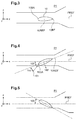
- a reference line 10REF of the pitch stabilization means 10 is in this position in a reference plane PREF of the aircraft, such as a horizontal plane parallel to the longitudinal direction X and to the transverse direction Y.
- a reference cord represents a straight segment connecting the leading edge 10BA and the trailing edge 10BF of a reference profile.
- the positioning system 15 can bias at least one actuator to position the pitch stabilizing means 10 at a negative steering angle 100.
- the steering angle is counted negatively when the leading edge 10BA of the reference profile is arranged below the reference plane PREF.
- the figure 4 also clarifies that the steering angle 100 of the pitch stabilizing means 10 differs from the incidence 150 of this pitch stabilizing means 10.
- the angle of incidence 150 represents the angle between said reference cord 10REF of the vector speed 151 of the incident wind. This incidence is representative of a lift force 160 generated by the pitch stabilization means.
- the positioning system 15 can bias at least one actuator to position the pitch stabilizing means 10 at a positive steering angle 100.
- the steering angle is counted positively when the leading edge 10BA of the reference profile is arranged above the reference plane PREF.
- the positioning system 15 may comprise an actuator 20 per aerodynamic stabilizing surface 11, 12.
- the positioning system 15 is provided with a processing unit 25 connected to each actuator.
- This processing unit may for example comprise a processor 26 or equivalent, and a memory 27.
- the processor 26 then applies instructions stored in the memory 27 to drive the actuators and achieve a proper steering angle for each aerodynamic stabilization surface.
- the processing unit may take different forms if necessary, for example comprising a printed circuit.
- the positioning system 15 has a measuring system 30 connected to the processing unit by at least one wired or non-wired connection.
- the measurement system 30 makes it possible to measure in flight at least one value called “flight value 51" of a parameter.
- This parameter is called “flight parameter”.
- a flight parameter makes it possible to characterize at least partially the position or the displacement of the aircraft in space, or the operation of certain organs of the aircraft.
- the measurement system may comprise usual equipment of the aircraft.
- the measurement system may comprise a first angular sensor 31 for measuring a flight parameter of the "longitudinal position parameter DDM" type.
- This longitudinal position parameter DDM represents a position of the lateral control control 8 controlling the longitudinal angle 180 mentioned above.
- the measurement system may comprise a second angular sensor 32 for measuring a flight parameter of the "lateral position parameter DDL" type.
- This lateral position parameter represents a position of the lateral control control controlling the aforementioned lateral angle.
- a flight parameter can also be a pitch attitude ⁇ of the aircraft, a rolling attitude ⁇ of the aircraft, an IAS air speed of the aircraft 1, or "Indicated Air Speed" in English, or a speed vertical Vz of the aircraft according to gravity.
- the measurement system comprises for example a unit 33 known by the acronym "AHRS" which is able to determine the attitude pitch and / or roll of the aircraft.
- the measurement system may also include an anemobarometric system 35 for determining the air speed IAS and / or the vertical speed Vz of the aircraft.
- a flight parameter can be the power consumed by the power plant 9.
- the measurement system may comprise the management means 34 of each engine 91, such as a management means known by the acronym FADEC.
- the processing unit can then determine the power consumed by the power plant 9 by exploiting the measures of the management means 34.
- the positioning system 15 has a determination system 40 for determining the value called "set value 60 *" of an incidence parameter.
- This incidence parameter may be the aerodynamic incidence 150 of the pitch stabilization means, ie the lift force 160 mentioned above, or a torsion moment measured on a visible shaft 300 on the figures 2 and 6 supporting the pitch stabilizing means.
- the determination system may comprise a button or equivalent that can be manipulated by a driver, or a computer integrated or not to the processing unit.
- a computer is connected to the measurement system to automatically determine a setpoint of an incidence parameter according to the flight phase.
- the determination system may be an integral part of the processing unit.
- the positioning system may include an instrument 600 for determining the current steering angle of the pitch stabilizing means.
- the instrument 600 has an angular sensor.
- a constructor develops a control law 20 during a preliminary phase STP1.
- the manufacturer acquires during a measurement step STP1.1 400 data at multiple measurement points 401 in order to develop the control law.
- These data 400 comprise at each measurement point 401 the values of the flight parameters 50, the value of the incidence parameter 60 and the steering angle 100 of the pitch stabilization means 10.
- This data can result from numerical simulations for example.
- a manufacturer instruments a test aircraft for this purpose.
- the aircraft can then comprise the measurement system 30 described above, and at least one instrument 600 measuring the steering angle of the pitch stabilization means.
- the aircraft is equipped with a temporary system for measuring the value of an incidence parameter, such as a wind vane measuring an incidence of the pitch stabilizing means or strain gauges measuring a lift force.
- an incidence parameter such as a wind vane measuring an incidence of the pitch stabilizing means or strain gauges measuring a lift force.
- each measuring point 401 is for example made by positioning the pitch stabilizing means 10 at a given steering angle and measuring in flight the values of the flight parameters 50 and incidence 60 in this position.
- At least one control law 200 is developed during an STP development step 1.2 by conventional mathematical methods.
- Each control law 200 outputs a set angle which must reach the steering angle of a stabilizing aerodynamic surface as a function, on the one hand, of at least one flight parameter 50 of the aircraft 1 and on the other hand, a parameter of incidence 60 of reference.
- a single control law 200 is set for a pitch stabilization means.
- the method makes it possible, for example, to establish a control law 200 for each aerodynamic stabilization surface of the pitch stabilization means 10.
- a control law 200 can take many forms, and for example the form of an algorithm comprising multiple processing 201.
- the control law 200 is for example stored in the processing unit 25, and in particular in the memory 27.
- a manufacturer implements each control law established in flight on series aircraft. The following steps are then performed in a loop.
- the so-called "flight value 51" value of each of the flight parameters 50 is determined using the measurement system.
- setpoint value 60 * of the incidence parameter 60 is determined.
- the setpoint step STP 2.2 is performed in parallel with the STP 2.1 flight parameter acquisition step, or before or even after this step of acquiring STP flight parameters 2.1.
- This setpoint value 60 * represents a steering angle to be attained with the pitch stabilization means.
- the reference value 60 * is established by implementing the determination system 40.
- the setpoint 60 * can be set by a pilot according to a first alternative.
- the setpoint value 60 * is established by using at least one incidence law that provides the setpoint value as a function of the flight phase.
- Each incidence law can be modulated by a modulation.
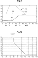
- the figure 9 presents two incidence laws 500 in a graph presenting a speed of advancement of the aircraft on the abscissa, and a value of the incidence parameter in ordinate.
- the determining system determines, for example, communicates with the measurement system to determine the current IAS speed, to deduce the setpoint value 60 *.
- the landing phase and the take-off phase can be identified either automatically according to flight parameters, or be specified by a pilot using a member that can be manipulated by this pilot such as a button.
- the figure 9 presents a curve 503 illustrating the incidence of a fixed stabilization means of a known aircraft with respect to its forward speed.
- the processing unit 25 determines a setpoint angle 100 * by inputting the flight values 51 and the command value 60 * into the control law 200.
- the processing unit then transmits during a setting step STP2.4 a signal to at least one actuator 20 so that the steering angle 100 of the pitch stabilizing means 10 reaches the setpoint angle 100 *. At least one actuator then moves at least one aerodynamic surface until the current steering angle of that aerodynamic surface reaches the set angle.
- the processing unit can safely limit the setpoint angle 100 * during the operational phase STP2.
- the setpoint angle 100 * is then bounded by at least one terminal 800 to not be greater or less than the terminal according to the nature of this terminal.
- a terminal can be an upper bound, the setpoint angle being maintained at the value of the upper bound when the setpoint angle provided by the control law is greater than or equal to said upper bound.
- the terminal may also be a lower terminal 801, the setpoint angle being maintained at the value of the lower terminal when the setpoint angle provided by the control law is less than or equal to said upper bound
- the figure 10 illustrates as an example an upper bound, the figure 10 showing a graph showing the value of the upper bound on the ordinate and the value of a forward speed on the abscissa.
Landscapes
- Engineering & Computer Science (AREA)
- Aviation & Aerospace Engineering (AREA)
- Automation & Control Theory (AREA)
- Radar, Positioning & Navigation (AREA)
- Remote Sensing (AREA)
- Physics & Mathematics (AREA)
- General Physics & Mathematics (AREA)
- Mechanical Engineering (AREA)
- Control Of Position, Course, Altitude, Or Attitude Of Moving Bodies (AREA)
- Aerodynamic Tests, Hydrodynamic Tests, Wind Tunnels, And Water Tanks (AREA)
Applications Claiming Priority (1)
| Application Number | Priority Date | Filing Date | Title |
|---|---|---|---|
| FR1500935A FR3035979B1 (fr) | 2015-05-05 | 2015-05-05 | Loi de commande avancee pour empennage braquable |
Publications (2)
| Publication Number | Publication Date |
|---|---|
| EP3091413A1 true EP3091413A1 (de) | 2016-11-09 |
| EP3091413B1 EP3091413B1 (de) | 2021-04-07 |
Family
ID=53872100
Family Applications (1)
| Application Number | Title | Priority Date | Filing Date |
|---|---|---|---|
| EP16167761.2A Active EP3091413B1 (de) | 2015-05-05 | 2016-04-29 | Fortgeschrittene steuerungsregel für ein lenkbares leitwerk |
Country Status (3)
| Country | Link |
|---|---|
| US (1) | US9703294B2 (de) |
| EP (1) | EP3091413B1 (de) |
| FR (1) | FR3035979B1 (de) |
Cited By (2)
| Publication number | Priority date | Publication date | Assignee | Title |
|---|---|---|---|---|
| US20210107625A1 (en) * | 2019-10-11 | 2021-04-15 | Bell Textron Inc. | Active horizontal stabilizer for high speed rotorcraft |
| CN115421426A (zh) * | 2022-09-27 | 2022-12-02 | 兰州交通大学 | 一种高速列车侧翼升力调控装置安装布置及协同控制方法 |
Families Citing this family (4)
| Publication number | Priority date | Publication date | Assignee | Title |
|---|---|---|---|---|
| CN111930096B (zh) * | 2020-07-24 | 2023-10-20 | 中国航空工业集团公司西安飞行自动控制研究所 | 一种飞控系统伺服阀接通故障诊断方法 |
| FR3117447B1 (fr) * | 2020-12-10 | 2022-11-04 | Airbus Helicopters | Procédé de pilotage d’un hélicoptère hybride ayant une cellule maintenue à incidence constante par régulation d’une position d’au moins un plan mobile d’empennage |
| CN117682056B (zh) * | 2023-12-15 | 2025-09-19 | 中国航空工业集团公司西安飞行自动控制研究所 | 一种尾旋改出方法 |
| US20260021913A1 (en) * | 2024-07-21 | 2026-01-22 | Wing Aviation Llc | Methods and Systems for Deep Stall Control of Uncrewed Aerial Vehicles |
Citations (13)
| Publication number | Priority date | Publication date | Assignee | Title |
|---|---|---|---|---|
| US2424882A (en) | 1945-02-02 | 1947-07-29 | United Aircraft Corp | Horizontal stabilizer for rotary wing aircraft |
| GB657796A (en) | 1948-02-27 | 1951-09-26 | Autogiro Co Of America | Adjustment mechanism for helicopter stabilizing surface |
| FR2067224A1 (de) | 1969-11-27 | 1971-08-20 | Sud Aviation | |
| FR2383475A1 (fr) | 1977-03-08 | 1978-10-06 | United Technologies Corp | Stabilisateur d'helicoptere a incidence variable, et dispositif de manoeuvre a l'epreuve des defaillances |
| FR2456663A1 (fr) | 1979-05-17 | 1980-12-12 | Textron Inc | Dispositif et procede de commande d'un helicoptere par des plans de stabilisation |
| EP0183282A2 (de) | 1984-11-28 | 1986-06-04 | The Boeing Company | Vorrichtung zur Verbesserung der Längsstabilität |
| EP0743582A2 (de) | 1995-05-15 | 1996-11-20 | The Boeing Company | Verfahren und Gerät zur linearen Echtzeitschätzung eines Flugzeugmassenmittelpunktes |
| FR2771706A1 (fr) | 1997-12-01 | 1999-06-04 | Eurocopter France | Dispositif de commande d'une surface aerodynamique d'equilibrage en tangage d'un helicoptere |
| WO2004007282A2 (en) | 2002-07-12 | 2004-01-22 | Carson Franklin D | A rotary-wing aircraft having horizontal stabilizer |
| EP1547920A1 (de) | 2003-12-23 | 2005-06-29 | Eurocopter | Verfahren und Vorrichtung zur Verminderung der Vibrationen eines Hubschrauberrumpfes, mittels eines steuerbaren Höhenleitwerks |
| WO2008142256A1 (fr) | 2007-05-22 | 2008-11-27 | Eurocopter | Hélicoptère hybride rapide à grande distance franchissable et avec contrôle de l'assiette longitudinale |
| FR2962972A1 (fr) | 2010-07-20 | 2012-01-27 | Eurocopter France | Procede et aeronef a voilure tournante muni d'un moyen de stabilisation minimisant le phenomene de bosse d'assiette |
| WO2015152910A1 (en) | 2014-04-02 | 2015-10-08 | Sikorsky Aircraft Corporation | Elevator load alleviating control for a rotary wing aircraft |
-
2015
- 2015-05-05 FR FR1500935A patent/FR3035979B1/fr not_active Expired - Fee Related
-
2016
- 2016-04-29 EP EP16167761.2A patent/EP3091413B1/de active Active
- 2016-05-04 US US15/146,081 patent/US9703294B2/en not_active Expired - Fee Related
Patent Citations (13)
| Publication number | Priority date | Publication date | Assignee | Title |
|---|---|---|---|---|
| US2424882A (en) | 1945-02-02 | 1947-07-29 | United Aircraft Corp | Horizontal stabilizer for rotary wing aircraft |
| GB657796A (en) | 1948-02-27 | 1951-09-26 | Autogiro Co Of America | Adjustment mechanism for helicopter stabilizing surface |
| FR2067224A1 (de) | 1969-11-27 | 1971-08-20 | Sud Aviation | |
| FR2383475A1 (fr) | 1977-03-08 | 1978-10-06 | United Technologies Corp | Stabilisateur d'helicoptere a incidence variable, et dispositif de manoeuvre a l'epreuve des defaillances |
| FR2456663A1 (fr) | 1979-05-17 | 1980-12-12 | Textron Inc | Dispositif et procede de commande d'un helicoptere par des plans de stabilisation |
| EP0183282A2 (de) | 1984-11-28 | 1986-06-04 | The Boeing Company | Vorrichtung zur Verbesserung der Längsstabilität |
| EP0743582A2 (de) | 1995-05-15 | 1996-11-20 | The Boeing Company | Verfahren und Gerät zur linearen Echtzeitschätzung eines Flugzeugmassenmittelpunktes |
| FR2771706A1 (fr) | 1997-12-01 | 1999-06-04 | Eurocopter France | Dispositif de commande d'une surface aerodynamique d'equilibrage en tangage d'un helicoptere |
| WO2004007282A2 (en) | 2002-07-12 | 2004-01-22 | Carson Franklin D | A rotary-wing aircraft having horizontal stabilizer |
| EP1547920A1 (de) | 2003-12-23 | 2005-06-29 | Eurocopter | Verfahren und Vorrichtung zur Verminderung der Vibrationen eines Hubschrauberrumpfes, mittels eines steuerbaren Höhenleitwerks |
| WO2008142256A1 (fr) | 2007-05-22 | 2008-11-27 | Eurocopter | Hélicoptère hybride rapide à grande distance franchissable et avec contrôle de l'assiette longitudinale |
| FR2962972A1 (fr) | 2010-07-20 | 2012-01-27 | Eurocopter France | Procede et aeronef a voilure tournante muni d'un moyen de stabilisation minimisant le phenomene de bosse d'assiette |
| WO2015152910A1 (en) | 2014-04-02 | 2015-10-08 | Sikorsky Aircraft Corporation | Elevator load alleviating control for a rotary wing aircraft |
Cited By (3)
| Publication number | Priority date | Publication date | Assignee | Title |
|---|---|---|---|---|
| US20210107625A1 (en) * | 2019-10-11 | 2021-04-15 | Bell Textron Inc. | Active horizontal stabilizer for high speed rotorcraft |
| US11685515B2 (en) * | 2019-10-11 | 2023-06-27 | Textron Innovations Inc. | Active horizontal stabilizer for high speed rotorcraft |
| CN115421426A (zh) * | 2022-09-27 | 2022-12-02 | 兰州交通大学 | 一种高速列车侧翼升力调控装置安装布置及协同控制方法 |
Also Published As
| Publication number | Publication date |
|---|---|
| EP3091413B1 (de) | 2021-04-07 |
| US9703294B2 (en) | 2017-07-11 |
| FR3035979A1 (fr) | 2016-11-11 |
| US20160327957A1 (en) | 2016-11-10 |
| FR3035979B1 (fr) | 2018-08-17 |
Similar Documents
| Publication | Publication Date | Title |
|---|---|---|
| EP3091413B1 (de) | Fortgeschrittene steuerungsregel für ein lenkbares leitwerk | |
| CA2817158C (fr) | Procede de commande des volets d'ailes et de l'empennage horizontal d'un helicoptere hybride | |
| EP2279941B1 (de) | Variable Dämpfung der haptischen Rückkopplung für die Bewegungsübertragung bei Änderung der Fluglage eines Luftfahrzeugs | |
| CA2817151C (fr) | Procede de commande des volets d'ailes et de l'empennage horizontal d'un helicoptere hybride | |
| WO2008142258A9 (fr) | Système de commande d'un giravion | |
| EP2963517B1 (de) | System und verfahren für die flugsteuerung eines drehflügelflugzeugs mit beibehaltung der flugbahn oder des kurses je nach vorschubgeschwindigkeit | |
| FR2943620A1 (fr) | Procede et dispositif pour optimiser le point de fonctionnement d'helices propulsives disposees de part et d'autre du fuselage d'un giravion | |
| EP3264214A1 (de) | Verfahren zur dynamischen fluglage-konvertierung eines drehflügeldrohne | |
| FR3036805A1 (fr) | Procede de determination de la vitesse air longitudinale et de la vitesse sol longitudinale d'un aeronef a voiture tournante selon son exposition au vent | |
| EP2597035B1 (de) | Hilfssteuerungsverfahren eines Drehflügelflugzeugs, das mindestens eine Druckschraube umfasst, Hilfssteuerungsvorrichtung und Luftfahrzeug | |
| EP2799331B1 (de) | System und Methode zur Steuerung eines Mittels zur Nickstabilisierung eines Fluggerätes. | |
| EP3260945A1 (de) | Drohne mit tragflügeln | |
| FR3108094A1 (fr) | procédé de commande d’au moins un organe aérodynamique de dérive d’un hélicoptère hybride et un hélicoptère hybride. | |
| EP1547919A1 (de) | Verfahren und Vorrichtung zur Verminderung der Vibrationen eines Hubschrauberrumpfes, mittels eines steuerbaren Rudders | |
| CA3157276C (fr) | Procede d'assistance au pilotage d'un giravion comportant au moins deux moteurs | |
| EP1547920A1 (de) | Verfahren und Vorrichtung zur Verminderung der Vibrationen eines Hubschrauberrumpfes, mittels eines steuerbaren Höhenleitwerks | |
| CA2935753A1 (fr) | Systeme de pilotage automatique d'aeronef et procede associe | |
| FR3117447A1 (fr) | Procédé de pilotage d’un hélicoptère hybride ayant une cellule maintenue à incidence constante par régulation d’une position d’au moins un plan mobile d’empennage | |
| EP1462900B1 (de) | Verfahren und Vorrichtung zur Dämpfung der durch Autorotation eines Triebwerkes verursachten Vibrationen in einem Flugzeug | |
| EP3882139B1 (de) | Verfahren zur automatischen regulierung des auftriebs eines hybriden drehflügelflugzeugs und entsprechendes hybrides drehflügelflugzeug | |
| FR3161411A1 (fr) | Aéronef à système de gestion du lacet et procédé de gestion du lacet | |
| FR3127473A1 (fr) | Procédé de vol stationnaire d'un aéronef au regard d'un axe avec un angle de tangage pilotable. | |
| FR3161412A1 (fr) | Aéronef à système de gestion du tangage et procédé de correction du tangage d’un aéronef | |
| FR3107252A1 (fr) | Procédé de commande d’un hélicoptère hybride lors d’une panne d’une installation motrice | |
| FR3110545A1 (fr) | Procédé d’optimisation d’une consommation d’énergie d’un hélicoptère hybride en vol en palier |
Legal Events
| Date | Code | Title | Description |
|---|---|---|---|
| PUAI | Public reference made under article 153(3) epc to a published international application that has entered the european phase |
Free format text: ORIGINAL CODE: 0009012 |
|
| AK | Designated contracting states |
Kind code of ref document: A1 Designated state(s): AL AT BE BG CH CY CZ DE DK EE ES FI FR GB GR HR HU IE IS IT LI LT LU LV MC MK MT NL NO PL PT RO RS SE SI SK SM TR |
|
| AX | Request for extension of the european patent |
Extension state: BA ME |
|
| STAA | Information on the status of an ep patent application or granted ep patent |
Free format text: STATUS: REQUEST FOR EXAMINATION WAS MADE |
|
| 17P | Request for examination filed |
Effective date: 20161123 |
|
| RBV | Designated contracting states (corrected) |
Designated state(s): AL AT BE BG CH CY CZ DE DK EE ES FI FR GB GR HR HU IE IS IT LI LT LU LV MC MK MT NL NO PL PT RO RS SE SI SK SM TR |
|
| STAA | Information on the status of an ep patent application or granted ep patent |
Free format text: STATUS: EXAMINATION IS IN PROGRESS |
|
| 17Q | First examination report despatched |
Effective date: 20171130 |
|
| GRAP | Despatch of communication of intention to grant a patent |
Free format text: ORIGINAL CODE: EPIDOSNIGR1 |
|
| STAA | Information on the status of an ep patent application or granted ep patent |
Free format text: STATUS: GRANT OF PATENT IS INTENDED |
|
| INTG | Intention to grant announced |
Effective date: 20201124 |
|
| GRAS | Grant fee paid |
Free format text: ORIGINAL CODE: EPIDOSNIGR3 |
|
| GRAA | (expected) grant |
Free format text: ORIGINAL CODE: 0009210 |
|
| STAA | Information on the status of an ep patent application or granted ep patent |
Free format text: STATUS: THE PATENT HAS BEEN GRANTED |
|
| AK | Designated contracting states |
Kind code of ref document: B1 Designated state(s): AL AT BE BG CH CY CZ DE DK EE ES FI FR GB GR HR HU IE IS IT LI LT LU LV MC MK MT NL NO PL PT RO RS SE SI SK SM TR |
|
| REG | Reference to a national code |
Ref country code: GB Ref legal event code: FG4D Free format text: NOT ENGLISH |
|
| REG | Reference to a national code |
Ref country code: AT Ref legal event code: REF Ref document number: 1380524 Country of ref document: AT Kind code of ref document: T Effective date: 20210415 Ref country code: CH Ref legal event code: EP |
|
| REG | Reference to a national code |
Ref country code: DE Ref legal event code: R096 Ref document number: 602016055517 Country of ref document: DE |
|
| REG | Reference to a national code |
Ref country code: IE Ref legal event code: FG4D Free format text: LANGUAGE OF EP DOCUMENT: FRENCH |
|
| REG | Reference to a national code |
Ref country code: LT Ref legal event code: MG9D |
|
| REG | Reference to a national code |
Ref country code: NL Ref legal event code: MP Effective date: 20210407 Ref country code: AT Ref legal event code: MK05 Ref document number: 1380524 Country of ref document: AT Kind code of ref document: T Effective date: 20210407 |
|
| PG25 | Lapsed in a contracting state [announced via postgrant information from national office to epo] |
Ref country code: AT Free format text: LAPSE BECAUSE OF FAILURE TO SUBMIT A TRANSLATION OF THE DESCRIPTION OR TO PAY THE FEE WITHIN THE PRESCRIBED TIME-LIMIT Effective date: 20210407 Ref country code: BG Free format text: LAPSE BECAUSE OF FAILURE TO SUBMIT A TRANSLATION OF THE DESCRIPTION OR TO PAY THE FEE WITHIN THE PRESCRIBED TIME-LIMIT Effective date: 20210707 Ref country code: HR Free format text: LAPSE BECAUSE OF FAILURE TO SUBMIT A TRANSLATION OF THE DESCRIPTION OR TO PAY THE FEE WITHIN THE PRESCRIBED TIME-LIMIT Effective date: 20210407 Ref country code: FI Free format text: LAPSE BECAUSE OF FAILURE TO SUBMIT A TRANSLATION OF THE DESCRIPTION OR TO PAY THE FEE WITHIN THE PRESCRIBED TIME-LIMIT Effective date: 20210407 Ref country code: NL Free format text: LAPSE BECAUSE OF FAILURE TO SUBMIT A TRANSLATION OF THE DESCRIPTION OR TO PAY THE FEE WITHIN THE PRESCRIBED TIME-LIMIT Effective date: 20210407 Ref country code: LT Free format text: LAPSE BECAUSE OF FAILURE TO SUBMIT A TRANSLATION OF THE DESCRIPTION OR TO PAY THE FEE WITHIN THE PRESCRIBED TIME-LIMIT Effective date: 20210407 |
|
| REG | Reference to a national code |
Ref country code: DE Ref legal event code: R119 Ref document number: 602016055517 Country of ref document: DE |
|
| PG25 | Lapsed in a contracting state [announced via postgrant information from national office to epo] |
Ref country code: RS Free format text: LAPSE BECAUSE OF FAILURE TO SUBMIT A TRANSLATION OF THE DESCRIPTION OR TO PAY THE FEE WITHIN THE PRESCRIBED TIME-LIMIT Effective date: 20210407 Ref country code: SE Free format text: LAPSE BECAUSE OF FAILURE TO SUBMIT A TRANSLATION OF THE DESCRIPTION OR TO PAY THE FEE WITHIN THE PRESCRIBED TIME-LIMIT Effective date: 20210407 Ref country code: NO Free format text: LAPSE BECAUSE OF FAILURE TO SUBMIT A TRANSLATION OF THE DESCRIPTION OR TO PAY THE FEE WITHIN THE PRESCRIBED TIME-LIMIT Effective date: 20210707 Ref country code: PL Free format text: LAPSE BECAUSE OF FAILURE TO SUBMIT A TRANSLATION OF THE DESCRIPTION OR TO PAY THE FEE WITHIN THE PRESCRIBED TIME-LIMIT Effective date: 20210407 Ref country code: PT Free format text: LAPSE BECAUSE OF FAILURE TO SUBMIT A TRANSLATION OF THE DESCRIPTION OR TO PAY THE FEE WITHIN THE PRESCRIBED TIME-LIMIT Effective date: 20210809 Ref country code: ES Free format text: LAPSE BECAUSE OF FAILURE TO SUBMIT A TRANSLATION OF THE DESCRIPTION OR TO PAY THE FEE WITHIN THE PRESCRIBED TIME-LIMIT Effective date: 20210407 Ref country code: IS Free format text: LAPSE BECAUSE OF FAILURE TO SUBMIT A TRANSLATION OF THE DESCRIPTION OR TO PAY THE FEE WITHIN THE PRESCRIBED TIME-LIMIT Effective date: 20210807 Ref country code: LV Free format text: LAPSE BECAUSE OF FAILURE TO SUBMIT A TRANSLATION OF THE DESCRIPTION OR TO PAY THE FEE WITHIN THE PRESCRIBED TIME-LIMIT Effective date: 20210407 Ref country code: GR Free format text: LAPSE BECAUSE OF FAILURE TO SUBMIT A TRANSLATION OF THE DESCRIPTION OR TO PAY THE FEE WITHIN THE PRESCRIBED TIME-LIMIT Effective date: 20210708 |
|
| PG25 | Lapsed in a contracting state [announced via postgrant information from national office to epo] |
Ref country code: LU Free format text: LAPSE BECAUSE OF NON-PAYMENT OF DUE FEES Effective date: 20210429 |
|
| REG | Reference to a national code |
Ref country code: BE Ref legal event code: MM Effective date: 20210430 |
|
| PG25 | Lapsed in a contracting state [announced via postgrant information from national office to epo] |
Ref country code: LI Free format text: LAPSE BECAUSE OF NON-PAYMENT OF DUE FEES Effective date: 20210430 Ref country code: MC Free format text: LAPSE BECAUSE OF FAILURE TO SUBMIT A TRANSLATION OF THE DESCRIPTION OR TO PAY THE FEE WITHIN THE PRESCRIBED TIME-LIMIT Effective date: 20210407 Ref country code: CH Free format text: LAPSE BECAUSE OF NON-PAYMENT OF DUE FEES Effective date: 20210430 Ref country code: RO Free format text: LAPSE BECAUSE OF FAILURE TO SUBMIT A TRANSLATION OF THE DESCRIPTION OR TO PAY THE FEE WITHIN THE PRESCRIBED TIME-LIMIT Effective date: 20210407 Ref country code: EE Free format text: LAPSE BECAUSE OF FAILURE TO SUBMIT A TRANSLATION OF THE DESCRIPTION OR TO PAY THE FEE WITHIN THE PRESCRIBED TIME-LIMIT Effective date: 20210407 Ref country code: DE Free format text: LAPSE BECAUSE OF NON-PAYMENT OF DUE FEES Effective date: 20211103 Ref country code: DK Free format text: LAPSE BECAUSE OF FAILURE TO SUBMIT A TRANSLATION OF THE DESCRIPTION OR TO PAY THE FEE WITHIN THE PRESCRIBED TIME-LIMIT Effective date: 20210407 Ref country code: CZ Free format text: LAPSE BECAUSE OF FAILURE TO SUBMIT A TRANSLATION OF THE DESCRIPTION OR TO PAY THE FEE WITHIN THE PRESCRIBED TIME-LIMIT Effective date: 20210407 Ref country code: SM Free format text: LAPSE BECAUSE OF FAILURE TO SUBMIT A TRANSLATION OF THE DESCRIPTION OR TO PAY THE FEE WITHIN THE PRESCRIBED TIME-LIMIT Effective date: 20210407 Ref country code: SK Free format text: LAPSE BECAUSE OF FAILURE TO SUBMIT A TRANSLATION OF THE DESCRIPTION OR TO PAY THE FEE WITHIN THE PRESCRIBED TIME-LIMIT Effective date: 20210407 |
|
| PLBE | No opposition filed within time limit |
Free format text: ORIGINAL CODE: 0009261 |
|
| STAA | Information on the status of an ep patent application or granted ep patent |
Free format text: STATUS: NO OPPOSITION FILED WITHIN TIME LIMIT |
|
| 26N | No opposition filed |
Effective date: 20220110 |
|
| PG25 | Lapsed in a contracting state [announced via postgrant information from national office to epo] |
Ref country code: IE Free format text: LAPSE BECAUSE OF NON-PAYMENT OF DUE FEES Effective date: 20210429 |
|
| PG25 | Lapsed in a contracting state [announced via postgrant information from national office to epo] |
Ref country code: IS Free format text: LAPSE BECAUSE OF FAILURE TO SUBMIT A TRANSLATION OF THE DESCRIPTION OR TO PAY THE FEE WITHIN THE PRESCRIBED TIME-LIMIT Effective date: 20210807 Ref country code: AL Free format text: LAPSE BECAUSE OF FAILURE TO SUBMIT A TRANSLATION OF THE DESCRIPTION OR TO PAY THE FEE WITHIN THE PRESCRIBED TIME-LIMIT Effective date: 20210407 |
|
| PG25 | Lapsed in a contracting state [announced via postgrant information from national office to epo] |
Ref country code: BE Free format text: LAPSE BECAUSE OF NON-PAYMENT OF DUE FEES Effective date: 20210430 |
|
| PG25 | Lapsed in a contracting state [announced via postgrant information from national office to epo] |
Ref country code: HU Free format text: LAPSE BECAUSE OF FAILURE TO SUBMIT A TRANSLATION OF THE DESCRIPTION OR TO PAY THE FEE WITHIN THE PRESCRIBED TIME-LIMIT; INVALID AB INITIO Effective date: 20160429 |
|
| PG25 | Lapsed in a contracting state [announced via postgrant information from national office to epo] |
Ref country code: CY Free format text: LAPSE BECAUSE OF FAILURE TO SUBMIT A TRANSLATION OF THE DESCRIPTION OR TO PAY THE FEE WITHIN THE PRESCRIBED TIME-LIMIT Effective date: 20210407 |
|
| P01 | Opt-out of the competence of the unified patent court (upc) registered |
Effective date: 20230530 |
|
| PGFP | Annual fee paid to national office [announced via postgrant information from national office to epo] |
Ref country code: GB Payment date: 20230419 Year of fee payment: 8 |
|
| PG25 | Lapsed in a contracting state [announced via postgrant information from national office to epo] |
Ref country code: MK Free format text: LAPSE BECAUSE OF FAILURE TO SUBMIT A TRANSLATION OF THE DESCRIPTION OR TO PAY THE FEE WITHIN THE PRESCRIBED TIME-LIMIT Effective date: 20210407 |
|
| PG25 | Lapsed in a contracting state [announced via postgrant information from national office to epo] |
Ref country code: MT Free format text: LAPSE BECAUSE OF FAILURE TO SUBMIT A TRANSLATION OF THE DESCRIPTION OR TO PAY THE FEE WITHIN THE PRESCRIBED TIME-LIMIT Effective date: 20210407 |
|
| GBPC | Gb: european patent ceased through non-payment of renewal fee |
Effective date: 20240429 |
|
| PG25 | Lapsed in a contracting state [announced via postgrant information from national office to epo] |
Ref country code: GB Free format text: LAPSE BECAUSE OF NON-PAYMENT OF DUE FEES Effective date: 20240429 |
|
| PG25 | Lapsed in a contracting state [announced via postgrant information from national office to epo] |
Ref country code: GB Free format text: LAPSE BECAUSE OF NON-PAYMENT OF DUE FEES Effective date: 20240429 |
|
| PGFP | Annual fee paid to national office [announced via postgrant information from national office to epo] |
Ref country code: IT Payment date: 20250424 Year of fee payment: 10 |
|
| PGFP | Annual fee paid to national office [announced via postgrant information from national office to epo] |
Ref country code: FR Payment date: 20250425 Year of fee payment: 10 |
|
| PG25 | Lapsed in a contracting state [announced via postgrant information from national office to epo] |
Ref country code: TR Free format text: LAPSE BECAUSE OF FAILURE TO SUBMIT A TRANSLATION OF THE DESCRIPTION OR TO PAY THE FEE WITHIN THE PRESCRIBED TIME-LIMIT Effective date: 20210407 |