EP3092015B1 - Blutverarbeitungseinheit mit einem wärmetauscherkern zur bereitstellung eines modifizierten fliesspfades - Google Patents
Blutverarbeitungseinheit mit einem wärmetauscherkern zur bereitstellung eines modifizierten fliesspfades Download PDFInfo
- Publication number
- EP3092015B1 EP3092015B1 EP14723134.4A EP14723134A EP3092015B1 EP 3092015 B1 EP3092015 B1 EP 3092015B1 EP 14723134 A EP14723134 A EP 14723134A EP 3092015 B1 EP3092015 B1 EP 3092015B1
- Authority
- EP
- European Patent Office
- Prior art keywords
- heat exchanger
- blood
- core
- hollow fibers
- end cap
- Prior art date
- Legal status (The legal status is an assumption and is not a legal conclusion. Google has not performed a legal analysis and makes no representation as to the accuracy of the status listed.)
- Active
Links
Images







Classifications
-
- A—HUMAN NECESSITIES
- A61—MEDICAL OR VETERINARY SCIENCE; HYGIENE
- A61M—DEVICES FOR INTRODUCING MEDIA INTO, OR ONTO, THE BODY; DEVICES FOR TRANSDUCING BODY MEDIA OR FOR TAKING MEDIA FROM THE BODY; DEVICES FOR PRODUCING OR ENDING SLEEP OR STUPOR
- A61M1/00—Suction or pumping devices for medical purposes; Devices for carrying-off, for treatment of, or for carrying-over, body-liquids; Drainage systems
- A61M1/14—Dialysis systems; Artificial kidneys; Blood oxygenators ; Reciprocating systems for treatment of body fluids, e.g. single needle systems for hemofiltration or pheresis
- A61M1/16—Dialysis systems; Artificial kidneys; Blood oxygenators ; Reciprocating systems for treatment of body fluids, e.g. single needle systems for hemofiltration or pheresis with membranes
- A61M1/1621—Constructional aspects thereof
- A61M1/1629—Constructional aspects thereof with integral heat exchanger
-
- A—HUMAN NECESSITIES
- A61—MEDICAL OR VETERINARY SCIENCE; HYGIENE
- A61M—DEVICES FOR INTRODUCING MEDIA INTO, OR ONTO, THE BODY; DEVICES FOR TRANSDUCING BODY MEDIA OR FOR TAKING MEDIA FROM THE BODY; DEVICES FOR PRODUCING OR ENDING SLEEP OR STUPOR
- A61M1/00—Suction or pumping devices for medical purposes; Devices for carrying-off, for treatment of, or for carrying-over, body-liquids; Drainage systems
- A61M1/14—Dialysis systems; Artificial kidneys; Blood oxygenators ; Reciprocating systems for treatment of body fluids, e.g. single needle systems for hemofiltration or pheresis
- A61M1/16—Dialysis systems; Artificial kidneys; Blood oxygenators ; Reciprocating systems for treatment of body fluids, e.g. single needle systems for hemofiltration or pheresis with membranes
- A61M1/1698—Blood oxygenators with or without heat-exchangers
-
- A—HUMAN NECESSITIES
- A61—MEDICAL OR VETERINARY SCIENCE; HYGIENE
- A61M—DEVICES FOR INTRODUCING MEDIA INTO, OR ONTO, THE BODY; DEVICES FOR TRANSDUCING BODY MEDIA OR FOR TAKING MEDIA FROM THE BODY; DEVICES FOR PRODUCING OR ENDING SLEEP OR STUPOR
- A61M1/00—Suction or pumping devices for medical purposes; Devices for carrying-off, for treatment of, or for carrying-over, body-liquids; Drainage systems
- A61M1/36—Other treatment of blood in a by-pass of the natural circulatory system, e.g. temperature adaptation, irradiation ; Extra-corporeal blood circuits
- A61M1/3621—Extra-corporeal blood circuits
- A61M1/3623—Means for actively controlling temperature of blood
-
- F—MECHANICAL ENGINEERING; LIGHTING; HEATING; WEAPONS; BLASTING
- F28—HEAT EXCHANGE IN GENERAL
- F28D—HEAT-EXCHANGE APPARATUS, NOT PROVIDED FOR IN ANOTHER SUBCLASS, IN WHICH THE HEAT-EXCHANGE MEDIA DO NOT COME INTO DIRECT CONTACT
- F28D21/00—Heat-exchange apparatus not covered by any of the groups F28D1/00 - F28D20/00
- F28D21/0015—Heat and mass exchangers, e.g. with permeable walls
-
- F—MECHANICAL ENGINEERING; LIGHTING; HEATING; WEAPONS; BLASTING
- F28—HEAT EXCHANGE IN GENERAL
- F28D—HEAT-EXCHANGE APPARATUS, NOT PROVIDED FOR IN ANOTHER SUBCLASS, IN WHICH THE HEAT-EXCHANGE MEDIA DO NOT COME INTO DIRECT CONTACT
- F28D7/00—Heat-exchange apparatus having stationary tubular conduit assemblies for both heat-exchange media, the media being in contact with different sides of a conduit wall
- F28D7/10—Heat-exchange apparatus having stationary tubular conduit assemblies for both heat-exchange media, the media being in contact with different sides of a conduit wall the conduits being arranged one within the other, e.g. concentrically
- F28D7/103—Heat-exchange apparatus having stationary tubular conduit assemblies for both heat-exchange media, the media being in contact with different sides of a conduit wall the conduits being arranged one within the other, e.g. concentrically consisting of more than two coaxial conduits or modules of more than two coaxial conduits
-
- F—MECHANICAL ENGINEERING; LIGHTING; HEATING; WEAPONS; BLASTING
- F28—HEAT EXCHANGE IN GENERAL
- F28F—DETAILS OF HEAT-EXCHANGE AND HEAT-TRANSFER APPARATUS, OF GENERAL APPLICATION
- F28F13/00—Arrangements for modifying heat-transfer, e.g. increasing, decreasing
- F28F13/06—Arrangements for modifying heat-transfer, e.g. increasing, decreasing by affecting the pattern of flow of the heat-exchange media
- F28F13/12—Arrangements for modifying heat-transfer, e.g. increasing, decreasing by affecting the pattern of flow of the heat-exchange media by creating turbulence, e.g. by stirring, by increasing the force of circulation
-
- A—HUMAN NECESSITIES
- A61—MEDICAL OR VETERINARY SCIENCE; HYGIENE
- A61M—DEVICES FOR INTRODUCING MEDIA INTO, OR ONTO, THE BODY; DEVICES FOR TRANSDUCING BODY MEDIA OR FOR TAKING MEDIA FROM THE BODY; DEVICES FOR PRODUCING OR ENDING SLEEP OR STUPOR
- A61M2206/00—Characteristics of a physical parameter; associated device therefor
- A61M2206/10—Flow characteristics
-
- A—HUMAN NECESSITIES
- A61—MEDICAL OR VETERINARY SCIENCE; HYGIENE
- A61M—DEVICES FOR INTRODUCING MEDIA INTO, OR ONTO, THE BODY; DEVICES FOR TRANSDUCING BODY MEDIA OR FOR TAKING MEDIA FROM THE BODY; DEVICES FOR PRODUCING OR ENDING SLEEP OR STUPOR
- A61M2206/00—Characteristics of a physical parameter; associated device therefor
- A61M2206/10—Flow characteristics
- A61M2206/12—Flow characteristics the flow being spirally in a plane, e.g. against a plane side of a membrane filter element
-
- B—PERFORMING OPERATIONS; TRANSPORTING
- B01—PHYSICAL OR CHEMICAL PROCESSES OR APPARATUS IN GENERAL
- B01D—SEPARATION
- B01D2313/00—Details relating to membrane modules or apparatus
- B01D2313/20—Specific housing
- B01D2313/203—Open housings
- B01D2313/2031—Frame or cage-like structures
-
- B—PERFORMING OPERATIONS; TRANSPORTING
- B01—PHYSICAL OR CHEMICAL PROCESSES OR APPARATUS IN GENERAL
- B01D—SEPARATION
- B01D2313/00—Details relating to membrane modules or apparatus
- B01D2313/22—Cooling or heating elements
- B01D2313/221—Heat exchangers
-
- B—PERFORMING OPERATIONS; TRANSPORTING
- B01—PHYSICAL OR CHEMICAL PROCESSES OR APPARATUS IN GENERAL
- B01D—SEPARATION
- B01D2313/00—Details relating to membrane modules or apparatus
- B01D2313/23—Specific membrane protectors, e.g. sleeves or screens
-
- F—MECHANICAL ENGINEERING; LIGHTING; HEATING; WEAPONS; BLASTING
- F28—HEAT EXCHANGE IN GENERAL
- F28D—HEAT-EXCHANGE APPARATUS, NOT PROVIDED FOR IN ANOTHER SUBCLASS, IN WHICH THE HEAT-EXCHANGE MEDIA DO NOT COME INTO DIRECT CONTACT
- F28D21/00—Heat-exchange apparatus not covered by any of the groups F28D1/00 - F28D20/00
- F28D2021/0019—Other heat exchangers for particular applications; Heat exchange systems not otherwise provided for
- F28D2021/005—Other heat exchangers for particular applications; Heat exchange systems not otherwise provided for for medical applications
Definitions
- the disclosure pertains generally to blood processing units used in blood perfusion systems.
- blood processing units are known, e.g., from EP 2 420 262 A1 and EP 2 524 712 A1 .
- Blood perfusion entails encouraging blood through the vessels of the body.
- blood perfusion systems typically entail the use of one or more pumps in an extracorporeal circuit that is interconnected with the vascular system of a patient.
- Cardiopulmonary bypass surgery typically requires a perfusion system that provides for the temporary cessation of the heart to create a still operating field by replacing the function of the heart and lungs. Such isolation allows for the surgical correction of vascular stenosis, valvular disorders, and congenital heart defects.
- an extracorporeal blood circuit is established that includes at least one pump and an oxygenation device to replace the functions of the heart and lungs.
- oxygen-poor blood i.e., venous blood
- venous blood is gravity-drained or vacuum suctioned from a large vein entering the heart or other veins in the body (e.g., femoral) and is transferred through a venous line in the extracorporeal circuit.
- the venous blood is pumped to an oxygenator that provides for oxygen transfer to the blood.
- Oxygen may be introduced into the blood by transfer across a membrane or, less frequently, by bubbling oxygen through the blood. Concurrently, carbon dioxide is removed across the membrane.
- the oxygenated blood is filtered and then returned through an arterial line to the aorta, femoral artery, or other artery.
- the invention pertains to a blood processing apparatus including a housing having a blood inlet and a blood outlet, the blood inlet extending into an interior of the housing.
- a heat exchanger core is arranged within the housing, the heat exchanger core including a core aperture in fluid communication with the blood inlet and configured to impart turbulence to blood passing from the blood inlet to an exterior of the heat exchanger core.
- Heat exchanger hollow fibers are disposed about the heat exchanger core such that a heat exchanger fluid may flow through the heat exchanger hollow fibers and blood passing from the core aperture may flow across the heat exchanger hollow fibers.
- a cylindrical shell extends coaxially about the heat exchanger core, the cylindrical shell including an annular shell aperture disposed near an end of the cylindrical shell opposite to an end near which the core aperture is located, the annular shell aperture configured to permit blood to pass to an exterior of the cylindrical shell.
- Gas exchanger hollow fibers are disposed about the cylindrical shell such that gases may flow through the gas exchange hollow fibers and blood passing from the annular shell aperture may flow across the gas exchanger hollow fibers.
- the disclosure pertains to a blood processing apparatus that, according to various exemplary embodiments, includes one or more of a heat exchanger and a gas exchanger (also commonly referred to as an oxygenator).
- the term oxygenator may be used to refer to an integrated structure that combines a heat exchanger and a gas exchanger in a unitary device.
- the heat exchanger and gas exchanger are disposed in a concentric fashion with one component located inside of the other component.
- the heat exchanger and gas exchanger are structurally distinct structures operable coupled to each other.
- an oxygenator may be used in an extracorporeal blood circuit.
- An extracorporeal blood circuit such as may be used in a bypass procedure, may include several different elements such as a heart-lung machine, a blood reservoir, as well as an oxygenator.
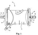
- FIG. 1 is a schematic illustration of a blood processing apparatus or oxygenator 10. While the internal components are not visible in this illustration, the oxygenator 10 may include one or more of a heat exchanger and a gas exchanger. According to some embodiments, the heat exchanger and the gas exchanger are integrated into a single structure that forms an oxygenator housing.
- the oxygenator 10 includes a housing 12, a first end cap 14 that is secured to the housing 12 and a second end cap 16 that is secured to the housing 12.
- the housing 12 may include other structure that enables attachment of the housing 12 to other devices. While the housing 12 is illustrated as largely cylindrical in shape, in some embodiments, the housing 12 may have a rectangular or other parallelogram cross-sectional shape.
- Each of the heat exchanger and the gas exchanger may have generally the same sectional shape or each may have a different sectional shape.
- the heat exchanger may be inside the gas exchanger while in other embodiments the gas exchanger may be located within the heat exchanger.
- the heat exchanger and the gas exchanger may be concentric.
- a blood inlet 18 extends into the housing 12 and a blood outlet 20 exits the housing 12.
- the blood processing apparatus 10 includes a gas exchanger and thus may include a gas inlet 22 and a gas outlet 24.
- the blood processing apparatus 10 includes a heat exchanger and thus may include a heat exchanger fluid inlet 26 and a heat exchanger fluid outlet 28 that is behind (in the illustrated orientation) the heating fluid inlet 26.
- the heat exchanger fluid inlet 26 may be disposed at one end of the housing 12 while the heat exchanger fluid outlet 28 may be disposed at an opposite end of the housing 12.
- the blood processing apparatus 10 may include a purge port 30 that may be used for purging air bubbles from the interior of the blood processing apparatus 10.
- the positions of the inlets, outlets and purge port are merely illustrative, as other arrangements and configurations are contemplated.
- the purge port may include a valve or a threaded cap.
- the purge port operates to permit gases (e.g., air bubbles) that exit the blood to be vented or aspirated and removed from the blood processing apparatus 10.
- Figures 2 and 3 illustrate the first end cap 14 and the second end cap 16, respectively.
- the first end cap 14 and the second end cap 16 are each configured to be secured to the housing 12.
- the first end cap 14 and/or the second end cap 16 may be adhesively secured in place.
- the first end cap 14 and/or the second end cap 16 may be snap-fitted into place or even threaded onto their respective ends of the housing 12.
- the blood inlet 18 and/or the gas inlet 22 may be integrally formed with the first end cap 14.
- the first end cap 14 may be injection molded with the blood inlet 18 and/or the gas inlet 22 formed as part of the injection molded part.
- the first end cap 14 may be formed having apertures to which the blood inlet 18 and/or the gas inlet 22 may be attached.
- the first end cap 14 includes an annular ring 32 that is disposed about a periphery of the first end cap 14 and that serves, in some embodiments, as an attachment point for securing the first end cap 14 to the housing 12.
- the first end cap 14 also includes an annular ring 34 that, as will be described subsequently, locates portions of the heat exchanger.
- the heat exchanger fluid inlet 26 and/or the heat exchanger fluid outlet 28 may be integrally formed with the second end cap 16.
- the second end cap 16 may be injection molded with the heat exchanger fluid inlet 26 and/or the heat exchanger fluid outlet 28 formed as part of the injection molded part.
- the second end cap 16 may be injected molded with the gas outlet 24 formed as part of the injection molded part.
- the second end cap 16 may be formed having apertures to which one or more of the heat exchanger fluid inlet 26, the heat exchanger fluid outlet 28 and/or the gas outlet 24 may be attached.
- the second end cap 16 includes an annular ring 36 that is disposed about a periphery of the second end cap 16 and that serves, in some embodiments, as an attachment point for securing the second end cap 16 to the housing 12.
- the second end cap 16 also includes an annular ring 38 that, as will be described subsequently, locates portions of the heat exchanger.
- one of the heat exchanger fluid inlet 26 and the heat exchanger fluid outlet 28 may be located in the first end cap 14 while the other of the heat exchanger fluid inlet 26 and the heat exchanger fluid outlet 28 may be located in the second end cap 16.
- the heat exchanger fluid inlet 26 and outlet 28 may be located in the first end cap 14. In some embodiments, the heat exchanger fluid inlet 26 and outlet 28 may be located in the second end cap 16.
- FIG 4A is a perspective illustration of a heat exchanger core 140 having a first end 142 and a second end 144.
- the heat exchanger core 140 may be disposed within the blood processing apparatus 10 such that the first end 142 is near the first end cap 14 while the second end 144 is near the second end cap 16.
- the heat exchanger core 140 includes cavities (not visible from the design) that, in some embodiments, help to locate the first end 142 relative to the first end cap 14 and similarly, the second end 144 to the second end cap 16.
- the annular portions 146 and 147 provide a desired distance between the fiber bundle (not illustrated) and the heat exchanger 140 in order to permit a desired volume and/or depth of potting resin.
- the heat exchanger core 140 includes a conical deflection surface (not visible in this orientation) upon which incoming blood from the blood inlet 18 impinges.
- the conical deflection surface deflects the blood in a radial direction.
- the conical deflection surface may include a divider (not shown) that assists in directing blood in particular directions.
- the heat exchanger core 140 includes an outer surface having one or more longitudinal ribs 153.
- the longitudinal ribs 153 provide mechanical support to the heat exchanger fiber bundle (not illustrated in Figure 4A ) and help to create a space between the fiber bundle and the heat exchanger core 140 in order to facilitate radial blood flow.
- a core aperture 154 is formed within the outer surface 152 such that blood impinging on the conical deflection surface is deflected radially outwardly through the core aperture 154.
- the heat exchanger core 140 may have one, two, three, four or any desired number of core apertures 154 spaced radially about the heat exchanger core 140.
- the heat exchanger core 140 includes radially disposed core ribs 152, 156.
- the core ribs (or projections) 152, 156 deflects blood away from the outer surface of the core in a radially-outward direction.
- the core ribs 152, 156 are designed to impart a radial component to blood flow trajectory.
- the heat exchanger core 140 may also have one or more longitudinally-extending indentations 160 that are disposed ahead of the core rib 156 and one or more longitudinally-extending indentations 162 that are disposed downstream of the core rib 156. In some embodiments, a plurality of the indentations 160 and 162 are disposed circumferentially around or substantially around the outer surface 152. In some embodiments, the heat exchanger core 140 is configured to provide turbulent blood flow while providing sufficient physical support for the heat exchanger hollow fibers (not illustrated).
- the indentations 160 include an angled surface 164, proximate the core rib 156, that provides a radially outward component to blood flow trajectory.
- the indentations 162 include a first tapered surface 166, a second tapered surface 168, a third tapered surface 170, a fourth tapered surface 172 and a bottom surface 174 that in combination assist in causing blood flow to move towards and away from the heat exchanger core 140.
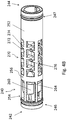
- FIG 4B is a perspective illustration of a heat exchanger core 240 having a first end 242 and a second end 244.
- the heat exchanger core 240 may be disposed within the blood processing apparatus 10 such that the first end 242 is near the first end cap 14 while the second end 244 is near the second end cap 16.
- the heat exchanger core 240 includes cavities (not illustrated in the drawing) that, in some embodiments, help to locate the first end 242 relative to the first end cap 14 and Similarly, the second end 244 relative to the second end cap 16.
- the annular portions 246 and 247 provide a desired distance between the fiber bundle (not illustrated) and the heat exchanger 240 in order to permit a desired volume and/or depth of potting resin.
- the heat exchanger core 240 includes a conical deflection surface (not visible in this orientation) upon which incoming blood from the blood inlet 18 impinges.
- the conical deflection surface deflects the blood in a radial direction.
- the conical deflection surface may include a divider (not shown) that assists in directing blood in particular directions.
- the heat exchanger core 240 includes an outer surface 252.
- a core aperture 254 is formed within the outer surface 252 such that blood impinging on the conical deflection surface is deflected radially outwardly through the core aperture 254.
- the heat exchanger core 240 may have one, two, three, four or any desired number of core apertures 254 spaced radially about the heat exchanger core 240.
- the heat exchanger core 240 includes a radially disposed core rib 256.
- the core rib (or projection) 256 deflects blood away from the outer surface 252 in a radially-outward direction.
- the core rib 256 is designed to impart a radial component to blood flow trajectory.
- the heat exchanger core 240 is configured to provide turbulent blood flow while providing sufficient physical support for the heat exchanger hollow fibers (not illustrated).
- the heat exchanger core 240 may also one or more longitudinally-extending indentations 260 that are disposed ahead of the core rib 256.
- a plurality of the indentations 260 are disposed circumferentially around or substantially around the outer surface 252.
- the indentations 260 include an angled surface 264, proximate the core rib 256, that provides a radially outward component to blood flow trajectory.
- the heat exchanger core 240 includes a blood turbulence section 270 that is disposed downstream of the core rib 256.
- the blood turbulence section 270 includes several longitudinally-extending ribs 272 that are intersected by radial ribs 274.
- the ribs 272 and the radial ribs 274 represent portions of the outer surface 252.
- a plurality of voids 276 are formed within the outer surface 252, in between the ribs 272 and the radial ribs 274. Blood impinging on the blood turbulence section 270 will splash off in a variety of directions, thereby improving blood flow across the heat exchanger hollow fibers (not illustrated).
- FIG 4C is a perspective illustration of a heat exchanger core 340 according to the claims and having a first end 342 and a second end 344.
- the heat exchanger core 340 may be disposed within the blood processing apparatus 10 such that the first end 342 is near the first end cap 14 while the second end 344 is near the second end cap 16.
- the heat exchanger core 340 includes cavities (349, while the second cavity is not presented in the drawing) that, in some embodiments, help to locate the first end 342 relative to the first end cap 14 and Similarly, the second end 344 relative to the second end cap 16.
- the annular portions 346 and 347 provide a desired distance between the fiber bundle (not illustrated) and the heat exchanger 340 in order to permit a desired volume and/or depth of potting resin.
- the heat exchanger core 340 includes a conical deflection surface 348 upon which incoming blood from the blood inlet 18 impinges.
- the conical deflection surface 348 deflects the blood in a radial direction.
- the conical deflection surface 348 may include a divider (not illustrated) that assists in directing blood in particular directions.
- the heat exchanger core 340 includes an outer surface 352.
- a core aperture 354 is formed within the outer surface 352 such that blood impinging on the conical deflection surface 348 is deflected radially outwardly through the core aperture 354.
- the heat exchanger core 340 may have one, two, three, four or any desired number of core apertures 354 spaced radially about the heat exchanger core 340.
- the heat exchanger core 340 is configured to provide turbulent blood flow while providing sufficient physical support for the heat exchanger hollow fibers (not illustrated).
- the heat exchanger core 340 includes a blood turbulence section 370 that is disposed downstream of the core rib 356.
- the blood turbulence section 370 includes a recessed portion 380 extending into the outer surface 352 and a grid 382 that extends across the recessed portion 380.
- the grid 382 extends at least substantially co-cylindrically with the outer surface 352.
- the grid 382 may be formed of any suitable metallic or polymeric material, and may be attached to the heat exchanger core 340 in any suitable manner.
- the grid 382 includes a plurality of apertures 384. The grid 382 provides mechanical support to the heat exchanger fiber bundle and provides a space for radial blood flow.
- Figure 5A is a perspective illustration of a cylindrical shell 62 that may be disposed within the housing 12 and arranged coaxially with the heat exchanger core 40 (see Figure 6 ).
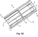
- Figure 5B is a cross-sectional view of the cylindrical shell 62.
- the cylindrical shell 62 includes a first end 64 and a second end 66.
- the cylindrical shell 62 may be disposed within the housing 12 such that the first end 64 is near the first end cap 14 while the second end 66 is near the second end cap 16.
- the cylindrical shell 62 includes an outer surface 68.
- a shell aperture 70 is formed within the outer surface 68 such that blood flowing between the outer surface 52 of the heat exchanger core 40 and an inner surface 72 of the cylindrical shell 62 can exit the cylindrical shell 62.
- the inner surface 72 of the cylindrical shell 62 may include one or more shell ribs 80 that protrude from the inner surface 72 and extend toward the heat exchanger core 140, 240, 340. The one or more shell ribs 80 deflect blood away from the inner surface 72 in a radially inward direction.
- the one or more shell ribs 80 may, in combination with the core ribs 56 and 58, interrupt longitudinal blood flow and impart a radial flow component to blood flow through the heat exchanger, i.e., between the outer surface 52 of the heat exchanger core 40 and the inner surface 72 of the cylindrical shell 72.
- the heat exchanger core 140, 240, 340 may also include one or more longitudinally-extending ribs 75 that may serve to create a distance between the heat exchanger fiber bundle and the cylindrical shell 72 in order to allow a radial flow path between the heat exchanger core 140, 240, 340 and the cylindrical shell 62.
- the cylindrical shell 62 may have one, two, three, four, five, six or any desired number of shell apertures 70 spaced radially about the cylindrical shell 62.
- the core aperture(s) 54 and the shell aperture(s) 70 are generally disposed at opposite ends of the blood processing apparatus 10.
- blood entering the volume between the outer surface 52 of the heat exchanger core 40 and an inner surface 72 of the cylindrical shell 62 is forced to flow at least substantially the entire length thereof before exiting the cylindrical shell 62.
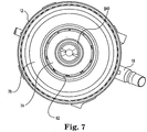
- Figure 7 is a cross-sectional illustration of an embodiment of the blood processing apparatus 10, illustrating the coaxial arrangement between the housing 12, the heat exchanger core 40 and the cylindrical shell 62.
- the blood processing apparatus 10 includes a schematically illustrated heat exchanger element 74 as well as a schematically illustrated gas exchanger element 76.
- the heat exchanger element 74 includes a number of hollow fibers through which a heating fluid such as water can flow.
- the blood may flow around and past the hollow fibers and thus be suitably heated.
- the hollow fibers may be polymeric. In some cases, metallic fibers may be used.
- the hollow fibers may be formed of polyurethane, polyester, or any other suitable polymer or plastic material. According to various embodiments, the hollow fibers have an outer diameter of between about 0.2 and 1.0 millimeters or, more specifically, between about 0.25 and 0.5 millimeters.
- the hollow fibers may be woven into mats that can range, for example, from about 20 to about 200 millimeters in width. In some embodiments, the mats are arranged in a criss-cross configuration.
- the gas exchanger element 76 may include a number of microporous hollow fibers through which a gas such as oxygen may flow.
- the blood may flow around and past the hollow fibers. Due to concentration gradients, oxygen may diffuse through the microporous hollow fibers into the blood while carbon dioxide may diffuse into the hollow fibers and out of the blood.
- the hollow fibers are made of polypropylene, polyester, or any other suitable polymer or plastic material. According to various embodiments, the hollow fibers have an outer diameter of about 0.38 millimeters. According to other embodiments, the microporous hollow fibers having a diameter of between about 0.2 and 1.0 millimeters, or more specifically, between about 0.25 and 0.5 millimeters.
- the hollow fibers may be woven into mats that can range, for example, from about 20 to about 200 millimeters in width. In some embodiments, the mats are in a criss-cross configuration.
- blood that enters the blood processing apparatus 10 through the blood inlet 18 is radially directed through the core aperture(s) 54 such that the blood flows over and around the hollow fibers within the heat exchanger element 74. At least some of the blood flow impinges on the inner surface 72 of the cylindrical shell 62 and is radially directed back towards the outer surface 52 of the heat exchanger core 140, 240, 340 (core 140 is illustrated). At least some of the blood flow is then directed radially outwards by the core ribs 56 and 58. The blood continues traveling back and forth radially until it reaches the shell aperture(s) 70 and enters a space between the cylindrical shell 62 and the housing 12.
- improved heat transfer may be achieved by combining radial and longitudinal flow through the heat exchanger element 74.
- the blood exiting the shell aperture(s) 70 flows over and around the gas exchanger element 76 and eventually exits the blood processing apparatus 10 through the blood outlet 20.
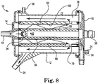
- FIG 8 is a cross-sectional view of the blood processing apparatus 10, illustrating the relative orientation of the elements previously discussed.
- the heat exchanger core is centrally located, with the heat exchanger element 74 coaxially disposed about the heat exchanger core 140, 240, 340 (core 140 is illustrated).
- the cylindrical shell 62 is coaxially disposed about the heat exchanger element 74, followed sequentially by the gas exchanger element 76 and the housing 12.
- the heat exchanger core 140, 240, 340 may have core ribs 56 and 58 that are configured to impart a radial component to blood flow trajectory across the heat exchanger element 74.
- the cylindrical shell 62 may have one or more radially disposed shell ribs 80 that are configured to impart a radial component to blood flow trajectory across the heat exchanger element 74.
- FIG. 9 is a cross-sectional view of a blood processing apparatus 90 in accordance with an embodiment of the invention.
- the blood processing apparatus 90 is similar to the blood processing apparatus 10, but includes a modified gas exchanger portion.
- an inner surface of the housing 12 includes one or more housing ribs 92 that are configured to impart a radial component to blood flow trajectory through and across the gas exchanger element 76.
- an outer surface of the cylindrical shell 62 includes one or more outer shell ribs 94 that are configured to impart a radial component to blood flow trajectory through and across the gas exchanger element 76.
- improved gas transfer may be achieved by combining radial and longitudinal flow through the gas exchanger element 76.
- the ribs such as the core ribs 56 and 58, the shell ribs 80 and/or the housing ribs 92 may extend about 10 to about 70 percent of the distance between a surface from which they extend to an opposing surface. In some embodiments, the ribs may extend about 25 to about 50 percent of the aforementioned distance. To illustrate, the core ribs 56 and 58 may extend about 10 to about 70 percent, or about 25 to about 50 percent, of a distance between the heat exchanger core 40 and the cylindrical shell 62. In some embodiments, the ribs may form an angle with the surface from which they extend that is in the range of about 30 to about 90 degrees. In some embodiments, the ribs may form an angle of about 45 to about 60 degrees. In some embodiments, the ribs may have a height that is in the range of about 0.2 millimeters to about 3 millimeters and a width that is in the range of about 0.5 millimeters to about 10 millimeters.
- FIG 10 is a cross-sectional view of a blood processing apparatus 100 in accordance with an embodiment of the invention.
- the blood processing apparatus 100 is similar to those discussed above, but blood flow through the heat exchanger has a spiral component.
- the blood processing apparatus 100 has a heat exchanger core 102 that includes one or more core apertures 104. Blood passes through the one or more core apertures 104 and enters a heat exchanger element 106 that as discussed above may include a number of hollow fibers. Blood exits the heat exchanger element 106 through one or more shell apertures 108 and then passes longitudinally through a gas exchanger element 112 before exiting through the blood outlet 20.
- the core apertures 104 and the shell apertures 108 are longitudinally spaced apart such that blood entering the heat exchanger element 106 passes the length of the heat exchanger element 106 before exiting into the gas exchanger element 112.
- the core apertures 104 and the shell apertures 108 are radially spaced apart from one another.
- the core apertures 104 may be spaced about 180 degrees apart from each other.
- the shell apertures 108 may also be spaced about 180 degrees apart from each other, and moreover may be radially displaced from the core apertures 104 by about 180 degrees.
Landscapes
- Health & Medical Sciences (AREA)
- Engineering & Computer Science (AREA)
- Heart & Thoracic Surgery (AREA)
- Urology & Nephrology (AREA)
- Vascular Medicine (AREA)
- Emergency Medicine (AREA)
- General Health & Medical Sciences (AREA)
- Anesthesiology (AREA)
- Life Sciences & Earth Sciences (AREA)
- Animal Behavior & Ethology (AREA)
- Biomedical Technology (AREA)
- Public Health (AREA)
- Veterinary Medicine (AREA)
- Hematology (AREA)
- Physics & Mathematics (AREA)
- Mechanical Engineering (AREA)
- General Engineering & Computer Science (AREA)
- Thermal Sciences (AREA)
- Cardiology (AREA)
- External Artificial Organs (AREA)
- Chemical & Material Sciences (AREA)
- Chemical Kinetics & Catalysis (AREA)
Claims (7)
- Ein Blutverarbeitungsgerät (10), umfassend:ein Gehäuse (12) mit einem Bluteinlass (18) und einem Blutauslass (20), wobei sich der Bluteinlass (18) in einen Innenbereich des Gehäuses (12) erstreckt;einen Wärmetauscherkern (340), der innerhalb des Gehäuses (12) angeordnet ist, wobei der Wärmetauscherkern (340) so konfiguriert ist, dass er dem Blut, das von dem Bluteinlass (18) zu einer Außenseite des Wärmetauscherkerns (340) fließt, eine radiale Strömung verleiht, wobei der Kern (340) eine oder mehrere Rippen aufweist, die Vertiefungen definieren;Wärmetauscherhohlfasern, die um den Wärmetauscherkern (340) herum angeordnet sind, so dass ein Wärmetauscherfluid durch die Wärmetauscherhohlfasern fließen kann und Blut aus der Kernöffnung (354) über die Wärmetauscherhohlfasern fließen kann;wobei die Wärmetauscherhohlfasern von einer oder mehreren Rippen des Wärmetauscherkerns (340) getragen werden (382);eine zylinderförmige Ummantelung (62), die sich koaxial um den Wärmetauscherkern (340) erstreckt, wobei die zylinderförmige Ummantelung (62) eine ringförmige Mantelöffnung (70) aufweist, die nahe einem zweiten Ende des Gehäuses (12) angeordnet ist, wobei die Mantelöffnung (70) ausgebildet ist, um das zu einer Außenseite des zylindrischen Mantels (62) fließende Blut mit einer Strömungskomponente in Längsrichtung zu versehen; undGasaustauschhohlfasern, die um die zylinderförmige Ummantelung (62) derart angeordnet sind, dass Gase durch die Gasaustauschhohlfasern strömen können und Blut, das von der ringförmigen Mantelöffnung (70) kommt, über die Gasaustauschhohlfasern fließen kann,dadurch gekennzeichnet, dass der Wärmetauscherkern (340) einen Blutverwirbelungsabschnitt (370) aufweist und der Blutverwirbelungsabschnitt (370) eine Ausnehmung (380), die innerhalb einer Außenfläche (352) des Wärmetauscherkerns (340) ausgebildet ist, und ein über der Ausnehmung (380) angeordnetes Gitter (382) umfasst, welches eine Vielzahl von Öffnungen (384) aufweist, die sich durch das Gitter (382) erstrecken.
- Das Blutverarbeitungsgerät (10) nach Anspruch 1, dadurch gekennzeichnet, dass die eine oder die mehreren Rippen eine oder mehrere radial angeordnete Kernrippen (356) umfassen, die so ausgebildet sind, dass sie die Wärmetauscherhohlfasern tragen und den Blutfluss mit einer radialen Strömungskomponente über die Wärmetauscherhohlfasern versehen.
- Das Blutverarbeitungsgerät (10) nach Anspruch 1, dadurch gekennzeichnet, dass der Wärmetauscherkern eine konische Ablenkfläche (356) aufweist, die zwischen dem Bluteinlass (18) und der Kernöffnung (354) angeordnet ist, wobei die konische Ablenkfläche der die Kernfläche verlassenden Blutströmung eine radiale Strömungskomponente verleiht.
- Das Blutverarbeitungsgerät (10) nach Anspruch 1, dadurch gekennzeichnet, dass das Gehäuse (12) eine Innenfläche aufweist, auf der eine oder mehrere radial angeordnete Gehäuserippen (92) angeordnet sind, wobei die eine oder mehrere radial angeordnete Gehäuserippen (92) konfiguriert sind, um der Blutströmung eine radiale Strömungskomponente über die Gasaustauschhohlfasern zu verleihen.
- Das Blutverarbeitungsgerät nach Anspruch 1, ferner umfassend eine erste an dem Gehäuse (12) befestigte Endkappe (14), wobei der Bluteinlass (18) einstückig mit der ersten Endkappe (14) ausgebildet ist.
- Das Blutverarbeitungsgerät (10) nach Anspruch 1, ferner umfassend eine zweite an dem Gehäuse (12) befestigte Endkappe (16), wobei die zweite Endkappe (16) einen einstückig mit der zweiten Endkappe (18) ausgebildeten Wärmetauscherfluideinlass (26) und einen einstückig mit der zweiten Endkappe (18) ausgebildeten Wärmetauscherfluidauslass (28) umfasst, wobei der Wärmetauscherfluideinlass (26) und -auslass (28) jeweils in Fluidverbindung mit einem Innenbereich der Wärmetauscherhohlfasern stehen.
- Das Blutverarbeitungsgerät nach Anspruch 5, ferner umfassend einen Gasauslass (24), der mit der zweiten Endkappe (16) einstückig ausgebildet ist, wobei der Gasauslass (24) in Fluidverbindung mit einem Innenbereich der Gasaustauschhohlfasern steht.
Applications Claiming Priority (1)
| Application Number | Priority Date | Filing Date | Title |
|---|---|---|---|
| PCT/IT2014/000005 WO2015104725A1 (en) | 2014-01-09 | 2014-01-09 | Blood processing unit with heat exchanger core for providing modified flow path |
Publications (2)
| Publication Number | Publication Date |
|---|---|
| EP3092015A1 EP3092015A1 (de) | 2016-11-16 |
| EP3092015B1 true EP3092015B1 (de) | 2018-09-19 |
Family
ID=50687545
Family Applications (1)
| Application Number | Title | Priority Date | Filing Date |
|---|---|---|---|
| EP14723134.4A Active EP3092015B1 (de) | 2014-01-09 | 2014-01-09 | Blutverarbeitungseinheit mit einem wärmetauscherkern zur bereitstellung eines modifizierten fliesspfades |
Country Status (5)
| Country | Link |
|---|---|
| US (2) | US10098994B2 (de) |
| EP (1) | EP3092015B1 (de) |
| JP (1) | JP6297706B2 (de) |
| CN (1) | CN105899245B (de) |
| WO (1) | WO2015104725A1 (de) |
Families Citing this family (12)
| Publication number | Priority date | Publication date | Assignee | Title |
|---|---|---|---|---|
| EP2612685B1 (de) | 2010-08-19 | 2014-10-08 | Sorin Group Italia S.r.l. | Blutverarbeitungseinheit mit modifiziertem Fließpfad |
| EP3110472B1 (de) | 2014-02-28 | 2018-05-30 | Sorin Group Italia S.r.l. | System zur bereitstellung eines integriertem arterienfilters in einem oxygenator zur minimierung von zusätzlichem primingvolumen |
| WO2016075514A1 (en) | 2014-11-12 | 2016-05-19 | Sorin Group Italia S.R.L. | Elastic protection tube for a hollow fibre blood processing apparatus |
| JP6535108B2 (ja) | 2015-05-12 | 2019-06-26 | ソリン・グループ・イタリア・ソシエタ・ア・レスポンサビリタ・リミタータSorin Group Italia S.r.l. | ガス交換を減少させるための1つまたは複数の制限要素を有する血液ガス交換器 |
| CN109996573B (zh) * | 2016-11-29 | 2021-09-07 | 甘布罗伦迪亚股份公司 | 连接器结构、用于体外血液处理的系统和用于灌注血液处理单元的流体腔室的方法 |
| CN116328070B (zh) * | 2017-09-12 | 2026-04-17 | 东莞科威医疗器械有限公司 | 一种螺旋导流集成式膜式氧合器 |
| CN107432960B (zh) * | 2017-09-12 | 2024-01-09 | 东莞科威医疗器械有限公司 | 一种螺旋导流集成式膜式氧合器 |
| JP6948465B2 (ja) * | 2017-10-10 | 2021-10-13 | ソリン・グループ・イタリア・ソシエタ・ア・レスポンサビリタ・リミタータSorin Group Italia S.r.l. | 熱交換器(hex)内の向流血液/水流路を備えた血液処理ユニット(bpu) |
| WO2019150569A1 (ja) * | 2018-02-05 | 2019-08-08 | テルモ株式会社 | 人工肺及びその製造方法 |
| CN119075048A (zh) | 2019-01-29 | 2024-12-06 | 尼普洛株式会社 | 人工肺装置 |
| US11781813B2 (en) * | 2020-12-18 | 2023-10-10 | Hamilton Sundstrand Corporation | Multi-scale unitary radial heat exchanger core |
| US20250339593A1 (en) * | 2024-05-03 | 2025-11-06 | Chinabridge (Shenzhen) Medical Technology Co., Ltd. | Flow distribution structure for a blood processing unit |
Family Cites Families (102)
| Publication number | Priority date | Publication date | Assignee | Title |
|---|---|---|---|---|
| US3339341A (en) | 1965-12-22 | 1967-09-05 | Du Pont | Fluid separation process and apparatus |
| FR2214502B1 (de) | 1973-01-18 | 1976-05-14 | Rhone Poulenc Ind | |
| FR2231421B1 (de) | 1973-05-30 | 1976-05-07 | Rhone Poulenc Ind | |
| JPS5847373B2 (ja) | 1975-07-29 | 1983-10-21 | 松下電工株式会社 | 長尺絶縁被覆付トロリ−ワイヤ |
| JPS52126681A (en) | 1976-04-16 | 1977-10-24 | Asahi Chem Ind Co Ltd | Improved hollow fiber fluid separating apparatus |
| SE421999B (sv) | 1977-10-17 | 1982-02-15 | Gambro Dialysatoren | Anordning for diffusion och/eller filtration av emnen mellan tva fluider via semipermeabla membran vilken anordning innefattar parallellkopplade banor innehallande seriekopplade kamrar |
| IT1091268B (it) | 1977-12-15 | 1985-07-06 | Hospal Dasco Spa | Perfezionamento ad un emodializzatore |
| JPS5935631B2 (ja) | 1980-07-24 | 1984-08-29 | テルモ株式会社 | 体液「ろ」過装置 |
| US4707268A (en) | 1982-10-18 | 1987-11-17 | Baxter Travenol Laboratories, Inc. | Hollow fiber potted microfilter |
| US4902476A (en) | 1983-01-14 | 1990-02-20 | Baxter International Inc. | Heat exchanger and blood oxygenator apparatus |
| JPS59147603A (ja) | 1983-02-10 | 1984-08-24 | Kuraray Co Ltd | 保護体付き中空糸束 |
| JPS6053156A (ja) | 1983-09-01 | 1985-03-26 | 三菱レイヨン株式会社 | 血液浄化器 |
| EP0312125B1 (de) | 1983-11-11 | 1992-03-04 | TERUMO KABUSHIKI KAISHA trading as TERUMO CORPORATION | Einrichtung zum Aufnehmen und Behandeln von Blut |
| CA1251109A (en) | 1984-04-24 | 1989-03-14 | Tohru Takemura | Blood oxygenator using a hollow-fiber membrane |
| CA1258436A (en) | 1984-08-01 | 1989-08-15 | Michael A. Smoot | Mat structure for use in filtration devices |
| JPS63139562A (ja) | 1986-12-01 | 1988-06-11 | 株式会社 日本メデイカル・サプライ | 中空糸型人工肺 |
| US4758341A (en) | 1987-04-20 | 1988-07-19 | The Dow Chemical Company | Membrane separation device |
| JPS6440060A (en) | 1987-08-06 | 1989-02-10 | Ube Industries | Artificial lung provided with built-in heat exchanger |
| JPS6476868A (en) | 1987-09-18 | 1989-03-22 | Nippon Medical Supply | Improved pump-oxygenator |
| US5120501A (en) * | 1988-10-20 | 1992-06-09 | Baxter International Inc. | Integrated membrane blood oxygenator/heat exchanger |
| US5316724A (en) | 1989-03-31 | 1994-05-31 | Baxter International Inc. | Multiple blood path membrane oxygenator |
| JPH0347271A (ja) | 1989-07-14 | 1991-02-28 | Terumo Corp | 液体処理器 |
| US5270004A (en) | 1989-10-01 | 1993-12-14 | Minntech Corporation | Cylindrical blood heater/oxygenator |
| US5578267A (en) | 1992-05-11 | 1996-11-26 | Minntech Corporation | Cylindrical blood heater/oxygenator |
| EP0519132A1 (de) | 1989-10-18 | 1992-12-23 | Exxon Research And Engineering Company | Hohlfasermodul |
| JPH03169329A (ja) | 1989-11-30 | 1991-07-23 | Nok Corp | 中空糸膜モジュールの製造方法 |
| JP3228518B2 (ja) | 1990-12-14 | 2001-11-12 | 日機装株式会社 | 人工心肺装置 |
| JPH05177117A (ja) | 1991-10-23 | 1993-07-20 | Hisateru Takano | 物質交換装置 |
| JP3284568B2 (ja) | 1991-10-31 | 2002-05-20 | 株式会社ジェイ・エム・エス | 人工肺用入口ヘッダーおよびそれを使用した人工肺 |
| US5192439A (en) | 1992-02-03 | 1993-03-09 | Electromedics, Inc. | Blood collection reservoir and filter device |
| WO1994003266A1 (en) | 1992-08-03 | 1994-02-17 | Maloney James V Jr | Improved mass and thermal transfer means for use in heart lung machines, dialyzers, and other applications |
| IT1255820B (it) | 1992-08-10 | 1995-11-16 | Nicola Ghelli | Scambiatore di calore in circuito ematico extracorporeo |
| US5489413A (en) | 1992-11-03 | 1996-02-06 | Cobe Laboratories, Inc. | Hollow fiber blood oxygenator |
| US5501663A (en) | 1993-07-02 | 1996-03-26 | Medtronic Electromedics, Inc. | Inflatable percutaneous oxygenator with transverse hollow fibers |
| US5514095A (en) | 1994-04-04 | 1996-05-07 | Haemonetics Corporation | Apparatus for heating, filtering and eliminating gas from biological fluids |
| IT1271104B (it) | 1994-11-25 | 1997-05-26 | Dideco Spa | Ossigenatore di sangue con uno strato di capillari in membrana microporosa. |
| JPH08168525A (ja) | 1994-12-19 | 1996-07-02 | Terumo Corp | 中空糸膜型血液処理器の製造方法及びその製造装置 |
| US5651765A (en) | 1995-04-27 | 1997-07-29 | Avecor Cardiovascular Inc. | Blood filter with concentric pleats and method of use |
| WO1997000636A1 (en) | 1995-06-20 | 1997-01-09 | Poeshty K Andrew | Supporting structure to mount and hold cylindrical shaped element |
| DE59600309D1 (de) | 1995-09-25 | 1998-08-06 | Medos Medizintechnik Gmbh | Vorrichtung zur Behandlung von Flüssigkeiten, insbesondere von Blut |
| US5770149A (en) | 1995-10-31 | 1998-06-23 | Baxter International | Extracorporeal blood oxygenation system having integrated blood pump, heat exchanger and membrane oxygenator |
| US5762868A (en) | 1995-11-30 | 1998-06-09 | Minnesota Mining And Manufacturing Company | Blood oxygenator and heat exchanger |
| EP1371381A1 (de) | 1996-01-11 | 2003-12-17 | Medtronic, Inc. | Blutoxygenator mit Wärmeaustauscher |
| SE506613C2 (sv) | 1996-05-30 | 1998-01-19 | Votinex Management Sa | Filter- och värmeväxlaranordning |
| US5762869A (en) | 1996-07-24 | 1998-06-09 | Gish Biomedical, Inc. | Blood oxygenator |
| DE19782098T1 (de) | 1996-11-15 | 1999-11-18 | Scitec K K | Dialysierapparat vom Hohlfasertyp |
| JPH1147268A (ja) | 1997-08-06 | 1999-02-23 | Terumo Corp | 中空糸膜型人工肺 |
| US6241945B1 (en) | 1998-03-16 | 2001-06-05 | Life Science Holdings, Inc. | Modular combined pump, filtration, oxygenation and/or debubbler apparatus |
| BR9910313B1 (pt) | 1998-05-08 | 2008-11-18 | reservatàrio de sangue/permutador tÉrmico combinado. | |
| US6113782A (en) | 1998-07-28 | 2000-09-05 | Terumo Cardiovascular Systems Corporation | Potting of tubular bundles in housing |
| US6193681B1 (en) | 1998-09-14 | 2001-02-27 | American Immuno Tech, Llc. | Septicemia prevention and treatment system |
| JP3992377B2 (ja) | 1998-09-18 | 2007-10-17 | テルモ株式会社 | 熱交換機能内蔵中空糸膜型人工肺 |
| US6454999B1 (en) | 1998-12-30 | 2002-09-24 | Cardiovention, Inc. | Integrated blood pump and oxygenator system having extended blood flow path |
| JP4041254B2 (ja) | 1999-12-15 | 2008-01-30 | テルモ株式会社 | 中空糸膜型人工肺 |
| WO2001066237A1 (de) | 2000-03-07 | 2001-09-13 | Mat Adsorption Technologies Gmbh & Co. Kg | Modul mit membranelementen in cross-flow und in dead-end anordnung |
| US6459937B1 (en) | 2000-04-25 | 2002-10-01 | Pacesetter, Inc. | Endocardial pacing lead with detachable tip electrode assembly |
| IT1318742B1 (it) | 2000-08-08 | 2003-09-10 | Dideco Spa | Dispositivo ossigenatore del sangue in circuito extracorporeo. |
| US6730267B2 (en) | 2001-02-09 | 2004-05-04 | Cardiovention, Inc. | Integrated blood handling system having active gas removal system and methods of use |
| US6755894B2 (en) | 2001-05-02 | 2004-06-29 | Praxair Technology, Inc. | Hollow fiber membrane gas separation cartridge and gas purification assembly |
| US6623638B2 (en) | 2001-06-01 | 2003-09-23 | Baxter International Inc. | Hemodialyzer having improved dialysate perfusion |
| PL368341A1 (en) | 2001-09-25 | 2005-03-21 | Honda Giken Kogyo Kabushiki Kaisha | Heat accumulation unit and method of manufacturing the unit |
| CN2511309Y (zh) | 2001-11-16 | 2002-09-18 | 广东省医疗器械研究所 | 膜式氧合器 |
| US20030175149A1 (en) | 2002-03-18 | 2003-09-18 | Bruce Searles | Renewable, modifiable, membrane gas exchanger |
| JP4214910B2 (ja) | 2002-12-26 | 2009-01-28 | ニプロ株式会社 | 透析器およびその製造方法 |
| DE60331403D1 (de) | 2002-12-26 | 2010-04-08 | Nipro Corp | Dialysator und dessen Herstellungsverfahren |
| JP4337573B2 (ja) | 2004-02-10 | 2009-09-30 | 株式会社ジェイ・エム・エス | 熱交換器、その製造方法及び人工心肺装置 |
| DE102004012049B4 (de) | 2004-03-11 | 2006-02-09 | Siemens Ag | Verfahren zum Befestigen eines Blechpaketes für die Statorwicklung eines Linearmotors am Fahrweg |
| CN2772515Y (zh) * | 2004-04-23 | 2006-04-19 | 广东省医疗器械研究所 | 一种中空纤维膜式氧合器 |
| JP4366268B2 (ja) | 2004-07-23 | 2009-11-18 | テルモ株式会社 | 人工肺 |
| JP4455260B2 (ja) | 2004-10-12 | 2010-04-21 | ヤマハ発動機株式会社 | 部品搬送装置、表面実装機および部品試験装置 |
| DE102005031582A1 (de) | 2005-07-06 | 2007-01-11 | Maquet Cardiopulmonary Ag | Vorrichtung zur Behandlung von Blut in einem extrakorporalen Blutkreislauf |
| DE102005039446B4 (de) | 2005-08-18 | 2009-06-25 | Ilias-Medical Gmbh | Vorrichtung zur An- und Abreicherung von Stoffen in einer Flüssigkeit |
| ATE472344T1 (de) | 2005-08-22 | 2010-07-15 | St Jude Medical | Werkzeug zur befestigung einer herzstimulatorleitung an einem gewünschten punkt im herz |
| US20070107884A1 (en) | 2005-10-27 | 2007-05-17 | Sirkar Kamalesh K | Polymeric hollow fiber heat exchange systems |
| EP2305332B1 (de) | 2006-01-19 | 2018-08-08 | Terumo Kabushiki Kaisha | Oxygenator |
| JP4500776B2 (ja) | 2006-01-19 | 2010-07-14 | テルモ株式会社 | 人工肺 |
| ITMI20060490A1 (it) | 2006-03-17 | 2007-09-18 | Eurosets Srl | Dispositivo integrato per il rioscaldamento e l'ossigenazione del sangue in circuito extracorporeo |
| JP4855119B2 (ja) | 2006-03-28 | 2012-01-18 | テルモ株式会社 | フィルタ部材および人工肺 |
| JP4714082B2 (ja) | 2006-06-07 | 2011-06-29 | 株式会社東芝 | 屋外装置の発光素子表示構造 |
| DE102007010112A1 (de) | 2007-02-28 | 2008-09-04 | Rheinisch-Westfälische Technische Hochschule Aachen | Vorrichtung für den Stoff- und/oder Energieaustausch |
| JP5020111B2 (ja) | 2008-02-04 | 2012-09-05 | 株式会社小松製作所 | 油圧制御装置および油圧制御方法、油圧制御装置の調整方法 |
| US20100272607A1 (en) | 2009-04-23 | 2010-10-28 | Carpenter Walt L | Radial design oxygenator with heat exchanger and inlet mandrel |
| US20100272606A1 (en) | 2009-04-23 | 2010-10-28 | Carpenter Walt L | Radial flow oxygenator/heat exchanger |
| US20100269342A1 (en) | 2009-04-23 | 2010-10-28 | Carpenter Walt L | Method of making radial design oxygenator with heat exchanger |
| JP5828170B2 (ja) | 2009-04-23 | 2015-12-02 | メドトロニック,インコーポレイテッド | 熱交換器を有する径方向設計人工肺 |
| DK2295646T3 (da) | 2009-08-28 | 2012-07-23 | Bauer Maschinen Gmbh | Boreindretning og borefremgangsmåde |
| CN201510571U (zh) | 2009-09-29 | 2010-06-23 | 山东威高新生医疗器械有限公司 | 膜式氧合器 |
| JP5418275B2 (ja) | 2010-02-15 | 2014-02-19 | ニプロ株式会社 | 熱交換器および熱交換器一体型人工肺 |
| DE102010027973A1 (de) | 2010-04-20 | 2011-10-20 | Ilias-Medical Gmbh | Verfahren und Vorrichtung zur Herstellung eines Membranmodus |
| US8318092B2 (en) | 2010-04-29 | 2012-11-27 | Sorin Group Italia S.R.L. | Oxygenator with integrated arterial filter |
| US8388566B2 (en) | 2010-04-29 | 2013-03-05 | Sorin Group Italia, S.r.l. | Oxygenator with integrated arterial filter including filter frame |
| WO2011150216A1 (en) | 2010-05-26 | 2011-12-01 | The Charles Stark Draper Laboratory, Inc. | Microfabricated artificial lung assist device, and methods of use and manufacture thereof |
| EP2612685B1 (de) | 2010-08-19 | 2014-10-08 | Sorin Group Italia S.r.l. | Blutverarbeitungseinheit mit modifiziertem Fließpfad |
| EP2524712B1 (de) | 2011-05-17 | 2018-12-12 | Sorin Group Italia S.r.l. | Blutverarbeitungseinheit mit Blutquerstrom |
| WO2012066439A1 (en) | 2010-11-15 | 2012-05-24 | Sorin Group Italia S.R.L. | Blood processing unit with circumferential blood flow |
| US8518259B2 (en) | 2011-01-27 | 2013-08-27 | Medtronic, Inc. | De-airing oxygenator for treating blood in an extracorporeal blood circuit |
| JP5890827B2 (ja) | 2011-03-31 | 2016-03-22 | テルモ株式会社 | 人工肺 |
| US8865067B2 (en) | 2011-04-29 | 2014-10-21 | Medtronic, Inc. | Combination oxygenator and arterial filter device for treating blood in an extracorporeal blood circuit |
| US8685319B2 (en) | 2011-04-29 | 2014-04-01 | Medtronic, Inc. | Combination oxygenator and arterial filter device with a fiber bundle of continuously wound hollow fibers for treating blood in an extracorporeal blood circuit |
| JP5844585B2 (ja) | 2011-09-15 | 2016-01-20 | ソリン・グループ・イタリア・ソシエタ・ア・レスポンサビリタ・リミタータ | 変更された流路を有する血液処理ユニット |
| JP6558595B2 (ja) | 2014-01-20 | 2019-08-14 | ユーロセッツ エス.アール.エル. | 患者の血液の体外酸素投与のための装置 |
| EP3110472B1 (de) | 2014-02-28 | 2018-05-30 | Sorin Group Italia S.r.l. | System zur bereitstellung eines integriertem arterienfilters in einem oxygenator zur minimierung von zusätzlichem primingvolumen |
-
2014
- 2014-01-09 US US15/110,684 patent/US10098994B2/en not_active Ceased
- 2014-01-09 WO PCT/IT2014/000005 patent/WO2015104725A1/en not_active Ceased
- 2014-01-09 US US17/068,190 patent/USRE49759E1/en active Active
- 2014-01-09 EP EP14723134.4A patent/EP3092015B1/de active Active
- 2014-01-09 CN CN201480072494.2A patent/CN105899245B/zh active Active
- 2014-01-09 JP JP2016545788A patent/JP6297706B2/ja not_active Expired - Fee Related
Non-Patent Citations (1)
| Title |
|---|
| None * |
Also Published As
| Publication number | Publication date |
|---|---|
| WO2015104725A1 (en) | 2015-07-16 |
| EP3092015A1 (de) | 2016-11-16 |
| USRE49759E1 (en) | 2023-12-19 |
| JP2017507686A (ja) | 2017-03-23 |
| CN105899245B (zh) | 2018-02-06 |
| US20160325036A1 (en) | 2016-11-10 |
| CN105899245A (zh) | 2016-08-24 |
| US10098994B2 (en) | 2018-10-16 |
| JP6297706B2 (ja) | 2018-03-20 |
Similar Documents
| Publication | Publication Date | Title |
|---|---|---|
| US12171923B2 (en) | Blood processing unit with modified flow path | |
| EP3092015B1 (de) | Blutverarbeitungseinheit mit einem wärmetauscherkern zur bereitstellung eines modifizierten fliesspfades | |
| EP2524712B1 (de) | Blutverarbeitungseinheit mit Blutquerstrom | |
| JP5844585B2 (ja) | 変更された流路を有する血液処理ユニット | |
| US10814056B2 (en) | Elastic protection tube for a hollow fiber blood processing apparatus | |
| WO2012066439A1 (en) | Blood processing unit with circumferential blood flow | |
| JP6030210B2 (ja) | 変更された流路を有する血液処理ユニット | |
| EP3694575A1 (de) | Blutbehandlungseinheit (bpu) mit im gegenstrom betriebenen blut-/wasserströmungswegen im wärmetauscher (hex) |
Legal Events
| Date | Code | Title | Description |
|---|---|---|---|
| PUAI | Public reference made under article 153(3) epc to a published international application that has entered the european phase |
Free format text: ORIGINAL CODE: 0009012 |
|
| 17P | Request for examination filed |
Effective date: 20160627 |
|
| AK | Designated contracting states |
Kind code of ref document: A1 Designated state(s): AL AT BE BG CH CY CZ DE DK EE ES FI FR GB GR HR HU IE IS IT LI LT LU LV MC MK MT NL NO PL PT RO RS SE SI SK SM TR |
|
| AX | Request for extension of the european patent |
Extension state: BA ME |
|
| DAX | Request for extension of the european patent (deleted) | ||
| STAA | Information on the status of an ep patent application or granted ep patent |
Free format text: STATUS: EXAMINATION IS IN PROGRESS |
|
| 17Q | First examination report despatched |
Effective date: 20180227 |
|
| GRAP | Despatch of communication of intention to grant a patent |
Free format text: ORIGINAL CODE: EPIDOSNIGR1 |
|
| STAA | Information on the status of an ep patent application or granted ep patent |
Free format text: STATUS: GRANT OF PATENT IS INTENDED |
|
| INTG | Intention to grant announced |
Effective date: 20180503 |
|
| GRAS | Grant fee paid |
Free format text: ORIGINAL CODE: EPIDOSNIGR3 |
|
| GRAA | (expected) grant |
Free format text: ORIGINAL CODE: 0009210 |
|
| STAA | Information on the status of an ep patent application or granted ep patent |
Free format text: STATUS: THE PATENT HAS BEEN GRANTED |
|
| AK | Designated contracting states |
Kind code of ref document: B1 Designated state(s): AL AT BE BG CH CY CZ DE DK EE ES FI FR GB GR HR HU IE IS IT LI LT LU LV MC MK MT NL NO PL PT RO RS SE SI SK SM TR |
|
| REG | Reference to a national code |
Ref country code: GB Ref legal event code: FG4D |
|
| REG | Reference to a national code |
Ref country code: CH Ref legal event code: EP |
|
| REG | Reference to a national code |
Ref country code: AT Ref legal event code: REF Ref document number: 1042513 Country of ref document: AT Kind code of ref document: T Effective date: 20181015 |
|
| REG | Reference to a national code |
Ref country code: IE Ref legal event code: FG4D |
|
| REG | Reference to a national code |
Ref country code: DE Ref legal event code: R096 Ref document number: 602014032513 Country of ref document: DE |
|
| REG | Reference to a national code |
Ref country code: NL Ref legal event code: FP |
|
| PG25 | Lapsed in a contracting state [announced via postgrant information from national office to epo] |
Ref country code: SE Free format text: LAPSE BECAUSE OF FAILURE TO SUBMIT A TRANSLATION OF THE DESCRIPTION OR TO PAY THE FEE WITHIN THE PRESCRIBED TIME-LIMIT Effective date: 20180919 Ref country code: BG Free format text: LAPSE BECAUSE OF FAILURE TO SUBMIT A TRANSLATION OF THE DESCRIPTION OR TO PAY THE FEE WITHIN THE PRESCRIBED TIME-LIMIT Effective date: 20181219 Ref country code: NO Free format text: LAPSE BECAUSE OF FAILURE TO SUBMIT A TRANSLATION OF THE DESCRIPTION OR TO PAY THE FEE WITHIN THE PRESCRIBED TIME-LIMIT Effective date: 20181219 Ref country code: GR Free format text: LAPSE BECAUSE OF FAILURE TO SUBMIT A TRANSLATION OF THE DESCRIPTION OR TO PAY THE FEE WITHIN THE PRESCRIBED TIME-LIMIT Effective date: 20181220 Ref country code: LT Free format text: LAPSE BECAUSE OF FAILURE TO SUBMIT A TRANSLATION OF THE DESCRIPTION OR TO PAY THE FEE WITHIN THE PRESCRIBED TIME-LIMIT Effective date: 20180919 Ref country code: FI Free format text: LAPSE BECAUSE OF FAILURE TO SUBMIT A TRANSLATION OF THE DESCRIPTION OR TO PAY THE FEE WITHIN THE PRESCRIBED TIME-LIMIT Effective date: 20180919 Ref country code: RS Free format text: LAPSE BECAUSE OF FAILURE TO SUBMIT A TRANSLATION OF THE DESCRIPTION OR TO PAY THE FEE WITHIN THE PRESCRIBED TIME-LIMIT Effective date: 20180919 |
|
| REG | Reference to a national code |
Ref country code: LT Ref legal event code: MG4D |
|
| PG25 | Lapsed in a contracting state [announced via postgrant information from national office to epo] |
Ref country code: HR Free format text: LAPSE BECAUSE OF FAILURE TO SUBMIT A TRANSLATION OF THE DESCRIPTION OR TO PAY THE FEE WITHIN THE PRESCRIBED TIME-LIMIT Effective date: 20180919 Ref country code: AL Free format text: LAPSE BECAUSE OF FAILURE TO SUBMIT A TRANSLATION OF THE DESCRIPTION OR TO PAY THE FEE WITHIN THE PRESCRIBED TIME-LIMIT Effective date: 20180919 Ref country code: LV Free format text: LAPSE BECAUSE OF FAILURE TO SUBMIT A TRANSLATION OF THE DESCRIPTION OR TO PAY THE FEE WITHIN THE PRESCRIBED TIME-LIMIT Effective date: 20180919 |
|
| REG | Reference to a national code |
Ref country code: AT Ref legal event code: MK05 Ref document number: 1042513 Country of ref document: AT Kind code of ref document: T Effective date: 20180919 |
|
| PG25 | Lapsed in a contracting state [announced via postgrant information from national office to epo] |
Ref country code: RO Free format text: LAPSE BECAUSE OF FAILURE TO SUBMIT A TRANSLATION OF THE DESCRIPTION OR TO PAY THE FEE WITHIN THE PRESCRIBED TIME-LIMIT Effective date: 20180919 Ref country code: EE Free format text: LAPSE BECAUSE OF FAILURE TO SUBMIT A TRANSLATION OF THE DESCRIPTION OR TO PAY THE FEE WITHIN THE PRESCRIBED TIME-LIMIT Effective date: 20180919 Ref country code: AT Free format text: LAPSE BECAUSE OF FAILURE TO SUBMIT A TRANSLATION OF THE DESCRIPTION OR TO PAY THE FEE WITHIN THE PRESCRIBED TIME-LIMIT Effective date: 20180919 Ref country code: ES Free format text: LAPSE BECAUSE OF FAILURE TO SUBMIT A TRANSLATION OF THE DESCRIPTION OR TO PAY THE FEE WITHIN THE PRESCRIBED TIME-LIMIT Effective date: 20180919 Ref country code: IS Free format text: LAPSE BECAUSE OF FAILURE TO SUBMIT A TRANSLATION OF THE DESCRIPTION OR TO PAY THE FEE WITHIN THE PRESCRIBED TIME-LIMIT Effective date: 20190119 Ref country code: PL Free format text: LAPSE BECAUSE OF FAILURE TO SUBMIT A TRANSLATION OF THE DESCRIPTION OR TO PAY THE FEE WITHIN THE PRESCRIBED TIME-LIMIT Effective date: 20180919 Ref country code: CZ Free format text: LAPSE BECAUSE OF FAILURE TO SUBMIT A TRANSLATION OF THE DESCRIPTION OR TO PAY THE FEE WITHIN THE PRESCRIBED TIME-LIMIT Effective date: 20180919 |
|
| PG25 | Lapsed in a contracting state [announced via postgrant information from national office to epo] |
Ref country code: SK Free format text: LAPSE BECAUSE OF FAILURE TO SUBMIT A TRANSLATION OF THE DESCRIPTION OR TO PAY THE FEE WITHIN THE PRESCRIBED TIME-LIMIT Effective date: 20180919 Ref country code: PT Free format text: LAPSE BECAUSE OF FAILURE TO SUBMIT A TRANSLATION OF THE DESCRIPTION OR TO PAY THE FEE WITHIN THE PRESCRIBED TIME-LIMIT Effective date: 20190119 Ref country code: SM Free format text: LAPSE BECAUSE OF FAILURE TO SUBMIT A TRANSLATION OF THE DESCRIPTION OR TO PAY THE FEE WITHIN THE PRESCRIBED TIME-LIMIT Effective date: 20180919 |
|
| REG | Reference to a national code |
Ref country code: DE Ref legal event code: R097 Ref document number: 602014032513 Country of ref document: DE |
|
| PLBE | No opposition filed within time limit |
Free format text: ORIGINAL CODE: 0009261 |
|
| STAA | Information on the status of an ep patent application or granted ep patent |
Free format text: STATUS: NO OPPOSITION FILED WITHIN TIME LIMIT |
|
| PG25 | Lapsed in a contracting state [announced via postgrant information from national office to epo] |
Ref country code: DK Free format text: LAPSE BECAUSE OF FAILURE TO SUBMIT A TRANSLATION OF THE DESCRIPTION OR TO PAY THE FEE WITHIN THE PRESCRIBED TIME-LIMIT Effective date: 20180919 |
|
| 26N | No opposition filed |
Effective date: 20190620 |
|
| PG25 | Lapsed in a contracting state [announced via postgrant information from national office to epo] |
Ref country code: MC Free format text: LAPSE BECAUSE OF FAILURE TO SUBMIT A TRANSLATION OF THE DESCRIPTION OR TO PAY THE FEE WITHIN THE PRESCRIBED TIME-LIMIT Effective date: 20180919 |
|
| REG | Reference to a national code |
Ref country code: CH Ref legal event code: PL |
|
| PG25 | Lapsed in a contracting state [announced via postgrant information from national office to epo] |
Ref country code: LU Free format text: LAPSE BECAUSE OF NON-PAYMENT OF DUE FEES Effective date: 20190109 |
|
| REG | Reference to a national code |
Ref country code: BE Ref legal event code: MM Effective date: 20190131 |
|
| REG | Reference to a national code |
Ref country code: IE Ref legal event code: MM4A |
|
| PG25 | Lapsed in a contracting state [announced via postgrant information from national office to epo] |
Ref country code: SI Free format text: LAPSE BECAUSE OF FAILURE TO SUBMIT A TRANSLATION OF THE DESCRIPTION OR TO PAY THE FEE WITHIN THE PRESCRIBED TIME-LIMIT Effective date: 20180919 |
|
| PG25 | Lapsed in a contracting state [announced via postgrant information from national office to epo] |
Ref country code: BE Free format text: LAPSE BECAUSE OF NON-PAYMENT OF DUE FEES Effective date: 20190131 |
|
| PG25 | Lapsed in a contracting state [announced via postgrant information from national office to epo] |
Ref country code: LI Free format text: LAPSE BECAUSE OF NON-PAYMENT OF DUE FEES Effective date: 20190131 Ref country code: CH Free format text: LAPSE BECAUSE OF NON-PAYMENT OF DUE FEES Effective date: 20190131 |
|
| PG25 | Lapsed in a contracting state [announced via postgrant information from national office to epo] |
Ref country code: IE Free format text: LAPSE BECAUSE OF NON-PAYMENT OF DUE FEES Effective date: 20190109 |
|
| PG25 | Lapsed in a contracting state [announced via postgrant information from national office to epo] |
Ref country code: TR Free format text: LAPSE BECAUSE OF FAILURE TO SUBMIT A TRANSLATION OF THE DESCRIPTION OR TO PAY THE FEE WITHIN THE PRESCRIBED TIME-LIMIT Effective date: 20180919 |
|
| PGFP | Annual fee paid to national office [announced via postgrant information from national office to epo] |
Ref country code: NL Payment date: 20200130 Year of fee payment: 7 |
|
| PG25 | Lapsed in a contracting state [announced via postgrant information from national office to epo] |
Ref country code: MT Free format text: LAPSE BECAUSE OF NON-PAYMENT OF DUE FEES Effective date: 20190109 |
|
| PG25 | Lapsed in a contracting state [announced via postgrant information from national office to epo] |
Ref country code: CY Free format text: LAPSE BECAUSE OF FAILURE TO SUBMIT A TRANSLATION OF THE DESCRIPTION OR TO PAY THE FEE WITHIN THE PRESCRIBED TIME-LIMIT Effective date: 20180919 |
|
| PG25 | Lapsed in a contracting state [announced via postgrant information from national office to epo] |
Ref country code: HU Free format text: LAPSE BECAUSE OF FAILURE TO SUBMIT A TRANSLATION OF THE DESCRIPTION OR TO PAY THE FEE WITHIN THE PRESCRIBED TIME-LIMIT; INVALID AB INITIO Effective date: 20140109 |
|
| REG | Reference to a national code |
Ref country code: NL Ref legal event code: MM Effective date: 20210201 |
|
| PG25 | Lapsed in a contracting state [announced via postgrant information from national office to epo] |
Ref country code: NL Free format text: LAPSE BECAUSE OF NON-PAYMENT OF DUE FEES Effective date: 20210201 |
|
| PG25 | Lapsed in a contracting state [announced via postgrant information from national office to epo] |
Ref country code: MK Free format text: LAPSE BECAUSE OF FAILURE TO SUBMIT A TRANSLATION OF THE DESCRIPTION OR TO PAY THE FEE WITHIN THE PRESCRIBED TIME-LIMIT Effective date: 20180919 |
|
| P01 | Opt-out of the competence of the unified patent court (upc) registered |
Effective date: 20230516 |
|
| PGFP | Annual fee paid to national office [announced via postgrant information from national office to epo] |
Ref country code: GB Payment date: 20251204 Year of fee payment: 13 |
|
| PGFP | Annual fee paid to national office [announced via postgrant information from national office to epo] |
Ref country code: FR Payment date: 20251208 Year of fee payment: 13 |
|
| PGFP | Annual fee paid to national office [announced via postgrant information from national office to epo] |
Ref country code: DE Payment date: 20251203 Year of fee payment: 13 |
|
| PGFP | Annual fee paid to national office [announced via postgrant information from national office to epo] |
Ref country code: IT Payment date: 20251219 Year of fee payment: 13 |